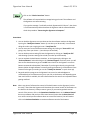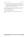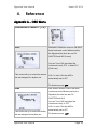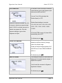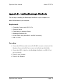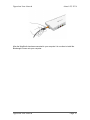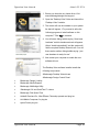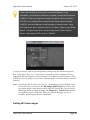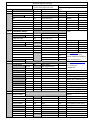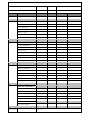
1
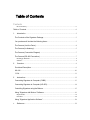
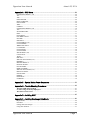
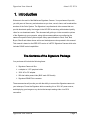
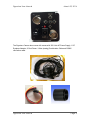
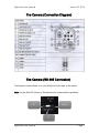
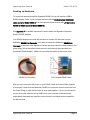
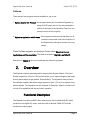
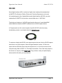
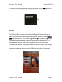
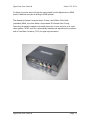
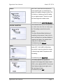
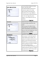
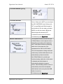
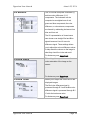
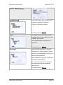
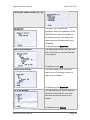
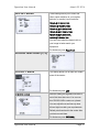
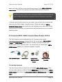
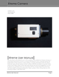
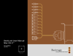
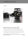
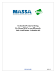
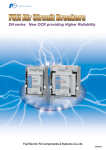
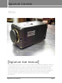
Signature Camera Revision Sheet [Version 1.2] Michael Burns [Signature User Manual] This document will introduce you to the wonders of the Mallincam Signature Camera. It will include instructions on how to connect the Signature to your computer along with explanations of the camera’s various settings. Imaging techniques with the various hardware and software options will be covered. Both the standard CVBS video output and SDI video output will be discussed along with hints and suggestions on how to resolve any problems that you encounter with this camera. Enjoy the adventure with Rock Mallin’s professional SDI video camera, this his Signature masterpiece. Signature User Manual Page i Revision Sheet Revision History Version Date Revision Description 1.0 3/22/2014 Template Creation 1.1 3/23/2014 Typo’s 1.2 3/24/2014 Added Appendix F specifically for RS485 Adapters Signature User Manual Page ii Table of Contents Contents Revision History ................................................................................................................................... ii Table of Contents .......................................................................................................................... 0 1. Introduction ............................................................................................................................ 3 The Contents of the Signature Package ................................................................................ 3 You purchase will include the following items:...................................................................... 3 The Camera (Just the Facts) ................................................................................................... 4 The Camera (its Anatomy) ....................................................................................................... 5 The Camera (Connection Diagram) ....................................................................................... 7 The Camera (RS-485 Connection) ......................................................................................... 7 Hooking up Hardware ............................................................................................................................ 8 Software ................................................................................................................................................. 9 2. Overview................................................................................................................................. 9 Functional Description .............................................................................................................. 9 HD-SDI ...................................................................................................................................... 10 CVBS ......................................................................................................................................... 11 3. Instructions ........................................................................................................................... 13 Connecting Signature to Computer (CVBS)........................................................................ 13 Connecting Signature to Computer (HD-SDI) ..................................................................... 14 Controlling Signature using the Buttons .............................................................................. 15 Using “Signature with Buttons” Software ............................................................................. 19 Requirements: ...................................................................................................................................... 19 Procedure ............................................................................................................................................. 20 Using “Signature Application Software” ............................................................................... 24 4. Reference ............................................................................................................................. 28 Signature User Manual March 23, 2014 Appendix A – OSD Menu ....................................................................................................... 28 LUMINANCE MENU1 (1/4) .............................................................................................................. 28 ALC ..................................................................................................................................................... 28 AES ...................................................................................................................................................... 28 FIX SHUTTER .................................................................................................................................... 29 PEAK AVERAGE ............................................................................................................................... 29 BACK LIGHT ..................................................................................................................................... 29 XDR ..................................................................................................................................................... 30 GAMMA.............................................................................................................................................. 30 LUMINANCE MENU2 (2/4) .............................................................................................................. 30 AGC ..................................................................................................................................................... 31 SLOW SHUTTER ............................................................................................................................... 31 DNR ..................................................................................................................................................... 31 DAY/NIGHT ....................................................................................................................................... 31 FOG REDUCTION ............................................................................................................................. 32 ECLIPSE .............................................................................................................................................. 32 ENHANCE .......................................................................................................................................... 32 COLOR MENU (3/4) .......................................................................................................................... 33 COLOR MODE ................................................................................................................................... 33 WHITE BALANCE ............................................................................................................................. 33 UV MATRIX ....................................................................................................................................... 34 COLOR GAIN ..................................................................................................................................... 34 COLOR TONE .................................................................................................................................... 34 SETUP MENU (4/4) ............................................................................................................................ 35 LANGUAGE ....................................................................................................................................... 35 TITLE .................................................................................................................................................. 35 DEFAULT ........................................................................................................................................... 35 SPECIAL FUNCTIONS (1/2) ............................................................................................................. 36 PRIORITY ........................................................................................................................................... 36 MOTION DETECT ............................................................................................................................. 36 DIGITAL ZOOM................................................................................................................................. 36 H/V REVERSE .................................................................................................................................... 36 DISPLAY MODE ................................................................................................................................ 37 SPECIAL FUNCTIONS (1/2) ............................................................................................................. 37 PRIVACY MASK ............................................................................................................................... 37 CROSS LINE ....................................................................................................................................... 37 FREEZE ............................................................................................................................................... 38 POSI/NEGA......................................................................................................................................... 38 COMM ID............................................................................................................................................ 38 Appendix B – Special Button Power Sequences ................................................................ 39 Appendix C – Trouble Shooting Procedures ....................................................................... 41 The Back LED doesn’t light up ........................................................................................................ 41 No Video Image from any output port ............................................................................................. 41 The OSD screen is frozen .................................................................................................................. 41 Appendix D – Installing MCV ................................................................................................. 43 Appendix E – Installing Blackmagic UltraStudio ................................................................. 46 Requirements: ...................................................................................................................................... 46 Procedure: ............................................................................................................................................ 46 Getting SDI Video Images ................................................................................................................... 49 Using other Software ........................................................................................................................... 51 Signature User Manual Page 1 Signature User Manual March 23, 2014 Appendix F – RS485 Connection Options ........................................................................... 53 US Converters RS485/422 cable converter Model Number XS890 ............................................... 53 Connecting Hardware .......................................................................................................................... 53 Installing Driver Software .................................................................................................................... 54 US Converters RS232 -RS485 Converter Model Number XS201A ............................................... 55 Connecting Hardware .......................................................................................................................... 55 Appendix G – Signature Setting Example Sheets .............................................................. 56 Appendix H – Notes ................................................................................................................ 57 Signature User Manual Page 2 Signature User Manual March 23, 2014 1. Introduction Welcome to the world of the Mallincam Signature Camera. Your purchase will provide you with years of discovery and adventure as you view, record, share, and broadcast the wonders of the Solar System. The Signature is a professional video camera that can provide broadcast quality live images in the HD-SDI format along with standard quality video for non-broadcast needs. This document will guide you in the connection options of the Signature to your computer, along with recommendations on configuring the camera for specific Solar System objects. Many special thanks to Rock, Jack, Bob, Bryan, Shevill and others whose advice and techniques are incorporated in this manual. This manual is based on the RED LED version of a NTSC Signature Camera which also includes RS485 control capabilities. The Contents of the Signature Package You purchase will include the following items: Signature Camera in Box c-adapter to 1.25” eyepiece holder 120V AC to DC adapter 25ft dual cable power/video (BNC male /RCA male) Signature RS485 Port connector These accessories will provide you with the ability to connect the Signature camera to your telescope, Power the Signature while connecting it to a 120V AC power source, and displaying your image on any device that accepts analog video via a RCA connection. Signature User Manual Page 3 Signature User Manual March 23, 2014 The Camera (Just the Facts) The Mallincam Signature Camera is the ultimate Solar, Lunar, and Planetary Video Camera ever made. This scientific instrument contains the following specifications: Image Sensor sCMOS CCD Pixels: 1384(H) by 1076(V) with 3.25 m Pixel size for a total of 1.49 Mega Pixels CCD Size: 1/3“ Lux: 0.1 Video Output Format: NTSC/PAL Multi Format Video Image Aspect: Output Full/Normal HDV: 16:9, SDV: 4:3/16:9 720p60, 1080p30,720p30,1080i60 720p50, 1080p25,720p25,1080i50 Analog Video Out CVBS Digital Video Out HD-SDI HD-SDI Bit Rate 1.485 GBits/sec Gain Control: Auto/Manual Exposure Control: Auto/Manual/Iris Priority Auto Iris: AES (Rolling Shutter), ALC Fix Shutter (s) 1/30, 1/50, 1/100, 1/120, 1/180, 1/350, 1/500, 1/750, 1/1000, 1/2000, 1/4000, 1/10000 Slow Shutter (s) 1/15, 1/8, 1/4, 1/2, 1, 2, 4, 8 S/N Ratio: 48dB Gamma Correction 0.45/0.7/1.0 Digital Zoom 4 times Communication Protocol RS484 (Red LED Version only) Operating Temperature -20oC to 50oC ( -4oF to 122oF Power Supply 12±1V DC at 3000mA Signature User Manual Page 4 Signature User Manual March 23, 2014 The Camera (its Anatomy) The Signature camera is 4.5” x 2” x 2” and weighs in at about 1 lb Signature User Manual Page 5 Signature User Manual March 23, 2014 The Signature Camera also comes with comes with 120 Volts AC Power Supply, 1.25" Eyepiece Adapter, 25 foot Power / Video (analog) Combination Cable and RS485 connection cable. Signature User Manual Page 6 Signature User Manual March 23, 2014 The Camera (Connection Diagram) The Camera (RS-485 Connection) The Signature communicates via a 3 pip RS485 port on the back of the camera Note: Only the Red LED Version of the Signature has communication capabilities. Ground R+ R- Signature User Manual Page 7 Signature User Manual March 23, 2014 Hooking up Hardware To control the camera through the Signature RS485 Port you will require a USB to RS485 Adapter Cable. I have had great success with the US Converters RS485/422 cable converter Model XS890 (other users also have had success with US Converters RS485 to RS232 converter Model XS201A). See Appendix F for detailed instructions of how to attach the Signature Camera to Specific RS485 Adapters. Your RS485 adapter must come with a means to connect it to the wires from the Mallincam RS485 Port Connector. You need to connect the Mallincam RS485 Port Connector to the back of the Signature Camera and then connect the three cables to the green thingy (this is the technical term we use in the industry) that came with your purchased “RS485 Adapter”. Make sure you match the cables in the correct order. RS485 Port Connector US Converter RS485 Cable Connector After you have connected the pieces on your RS485 Cable and secured them together to insure the 3 wires from the Mallincam RS485 Port connector cannot come loose from the Green Thingy (I used electrical tape to wrap them together). All you should need to do next is plug the cable into a free USB Port on your computer. Windows should automatically download and install the correct drivers from internet that are needed to run the converter. Signature User Manual Page 8 Signature User Manual March 23, 2014 Software There are two free programs that are available to you to use: 1. Buttons Control with Protocol –this program allows you to control the Signature by using the OSD menu just as if you are pressing the buttons on the back of the Signature (There is a nonprotocol version of this program). 2. Signature Application with Protocol- this program provides menus that allow you to connect to and control most of the functions of the Signature by clicking on choices of moving sliders. These Software programs are located in Folder named Signature Camera Applications and Documentation. The folder is located at http://sdrv.ms/Lb3wV3 See below in Chapter 3 on how to install and use these two programs. 2. Overview The Signature Camera was designed for imaging Solar System Objects. The Fixed Shutter ranges from 1/30s to 1/1000s which allows you to capture images of the bright Solar System objects (major planets, Sun and Moon). The Signature does provide a Slow Shutter capability that allows longer exposures from 1/15s to 8s to capture those dimmer objects. The Signature was not designed for Deep Sky Objects, but that is still not out of its capabilities with the end user’s expertise. Functional Description The Signature provides two BNC video outputs ports. One is labelled HD-SDI which produces a true digital SDI output, while the other is labelled CVBS OUT and this produces an analog signal. Signature User Manual Page 9 Signature User Manual March 23, 2014 HD-SDI Serial digital interface (SDI) is a family of digital video interfaces first standardized by SMPTE (The Society of Motion Picture and Television Engineers) and is used for broadcast-grade video. High-definition serial digital interface (HD-SDI), was also standardized in SMPTE; this provides a nominal data rate of 1.485 Gbit/s. The display and capture of a HD-SDI signal requires the use of a specialized BNC ended cable that meets the SMPTE standards and a HD-SDI capture device. A Google search can find various lengths of specific HD-SDI cable from many broadcasting vendors. I purchased mine form Markertek.com. To capture or display the HD-SDI video signal requires the use of both a HD-SDI capture device and a very fast computer. Since the signal standard is about 1.5 Gbit/s the capture devices will either be an internal computer card, or a box that connects to the computer using either a USB 3.0 or Thunderbolt connection. One of the major players in this arena is a company called Blackmagic. They provide a variety of capture/display devices which will match your requirements. Signature User Manual Page 10 Signature User Manual March 23, 2014 For those of you need to just display the output on a HDMI monitor, Sewell provides a very inexpensive SDI-HDMI converter called the Spector that will do the job for you. CVBS The CVBS OUT BNC connector on the back of the Signature Camera produces an analog signal that can be captured by any analog capture device such as the Mallincam MCV video capture device. CVBS stands for Composite Video, Blanking and Sync and is nothing more than the standard composite signal and thus requires the use of a composite video cable with a BNC male connector at one end and a RCA male connector at the other end. When you purchased the Signature camera, Rock will have provided you with a 25 foot Power/Video dual cable for you to use with the camera. The video portion of this cable is for the analog (CVBS) port on the back of the camera. Signature User Manual Page 11 Signature User Manual March 23, 2014 For those of you who want to display the analog signal from the Signature on a HDMI monitor, Mallincam provides an analog to HDMI upscaler. This device Up-Scales Composite Video, S-Video, and HDMI to 720p/1080p (selectable) HDMI. It provides Motion Compensated 3D Wavelet Video Coding Technology is applied to make the converted picture rich in color and more vivid. Input video systems - NTSC and PAL is automatically detected and adjusted and it provides a built-in Time Base Correction (T.B.C) for signal synchronization. Signature User Manual Page 12 Signature User Manual 3. March 23, 2014 Instructions Connecting Signature to Computer (CVBS) Requirements: Computer with video display software such as AMCAP USB Video capture adapter such as Mallincam MCV Mallincam dual power/video cable Signature AC to DC power adapter Signature camera Procedure: 1. Power on your computer. 2. Connect Signature Camera to Telescope and connect Video cable (BNC end) to the CVBS video jack on the back of the Mallincam (do not power Signature). Keep lens cap on Telescope. 3. Connect the USB Video Adapter to computer (see Installing MCV in the Appendix for instructions on how to install the Mallincam MCV Video adapter). 4. Connect other end of Video cable (RCA) to the Video Capture Device (MCV). 5. Power the Signature (plug in the AC to DC adapter and connect to the Signature). 6. Start the video display software (AMCAP). 7. Choose the Video Source for the software (USB 2828x Device for the MCV). 8. If necessary select Crossbar from AMCAP to choose the RCA connection on MCV rather than the S-video. 9. Hold down the Centre button on the back of the Signature for about 2 seconds (release when you see OSD menu on your Video Display Software) 10. Using the back buttons on the Signature, ensure that Signature is using Fix Shutter at a reasonable setting (see Appendix A – OSD Menu for instructions). 11. Remove Lens cap from Telescope. 12. Adjust settings using the OSD menu to match viewing object Signature User Manual Page 13 Signature User Manual March 23, 2014 Connecting Signature to Computer (HD-SDI) Requirements: Compatible Computer with software to display a SDI image (Blackmagic Media Express which is included free with the purchase of the UltraStudio SDI from Blackmagic) Signature Camera Power Supply for Signature Camera SDI Video Capture Device (Blackmagic UltraStudio SDI) HD-SDI Cable (SD59-BB50 - dual BNC connectors) Procedure: 1. Power on your computer. 2. Connect the Signature Camera to Telescope and connect Video Cable (BNC end) to the SDI-HD video jack on the back of the Mallincam (do not power Signature). Keep lens cap on Telescope. 3. Connect SDI Video Adapter to computer (see Installing Blackmagic Ultrastudio in the Appendix for detailed instructions on how to install and connect to the Blackmagic Ultrastudio Video adapter). 4. Connect other end of SDI Video cable to the Video Capture Device (Blackmagic Ultrastudio). 5. Power the Signature (plug in the AC to DC adapter and connect to the Signature). 6. Start the Video Display Software (Blackmagic Media Express). 7. Choose the Video source for the software (Blackmagic Ultrastudio). 8. Ensure all resolutions match from the Signature camera to the Video Capture Device to the Video Display Software (1030p). 9. Hold down the Centre button on the back of the Signature for about 2 seconds (release when you see OSD menu on your video display software) 10. Using the back buttons on the Signature, ensure that Signature is using Fix Shutter at a reasonable setting (see Appendix A – OSD Menu for instructions). 11. Remove Lens cap from Telescope. 12. Adjust settings using the OSD menu to match viewing object Signature User Manual Page 14 Signature User Manual March 23, 2014 Controlling Signature using the Buttons The Signature Camera has an OSD (On Screen Display) menu system that allows you to control every aspect of the camera. You activate the OSD by holding down the Centre Button for 2 to 3 seconds. When activated the following screen overlay will be presented. You control the arrow (see beside the ALC setting on the image above) by using the UP and DOWN Arrow Buttons on the back of the camera and you select an option by pressing the CENTRE (ENTER) Button. The LEFT and RIGHT Buttons take you other related screens. For example, with the LUMINANCE MENU1 (1/4) displayed press the RIGHT Button and you will see LUMINANCE MENU2 (2/4), Hit the RIGHT Button again and it will display the COLOR MENU (3/4) and finally hit RIGHT Button one more time to display the SETUP MENU (4/4). To can use the LEFT and RIGHT Buttons to cycle through the Main Menu screens. When the OSD is activated and NO Button activity has been detected by the Signature Camera for about a minute, the Signature will EXIT the OSD screen automatically. Signature User Manual Page 15 Signature User Manual March 23, 2014 To close the OSD, look for an EXIT option at the Bottom of a Main Menu, move the arrow to EXIT and press the CENTRE Button. Some Menu options may have its own SUB MENU (for example SPECIAL FUNCTIONS on the SETUP MENU (4/4)), when you are inside the SUB MENU you choose the RETURN option to return to MAIN MENU that called the SUB MENU. Again you can uses the LEFT and RIGHT Buttons to move from one SUB MENU to another if multiple SUB MENU’s are available. As an example to become familiar with the operation and use of the Buttons, we fill activate the FIX SHUTTER option from the LUMINANCE MENU1 and will set it to 1/2000. If the OSD is not activated, then activate it by holding down the CENTRE Button. Signature User Manual Page 16 Signature User Manual Step 1 March 23, 2014 Using the DOWN Button move the Arrow so it is next to the FIX SHUTTER Option on the LUMINANCE MENU 1 Step 2 Press the CENTRE Button to select this Option. The OSD will display the FIX SHUTTER Menu. Step 3 Press the CENTRE Button and the arrow will jump to the OFF or ON Option (depending upon what the Signature is set to). Using the UP or DOWN Button select ON and hit the CENTRE Button to select it. Step 4 The arrow should be pointing to the SHUTTER SPEED selection. Use the UP and DOWN Buttons keys to scroll through the Speed options, (Play and get familiar how to change the SHUTTER SPEED option. Stop when you had 1/2000 SEC displayed in the OSD window. Step 5 Press the LEFT Button to step back into the ON OFF options Step 6 Press the LEFT Button to step back to the FIX SHUTTER option Signature User Manual Page 17 Signature User Manual March 23, 2014 Step 7 Press the DOWN Button to select the RETURN option. Step 8 Press the CENTRE Button to return to the LUMINANCE MENU 1 (1/4) menu. Use the UP or DOWN Buttons to move arrow to EXIT, then press the Step 9 CENTRE Button to shut down the OSD Menu It is worth your time to become familiar on how to move around the OSD menu choices using the Back Buttons on the Signature Camera, As you will notice the amount of settings you can adjust on the Signature is astronomical (sorry), and each specific settings will be unique to you and your equipment and seeing conditions. See the APPENDIX A – OSD MENU for explanations on what the specific settings do and how that may be helpful to improve your image. Some settings deactivate other settings automatically while others affect the operation of the camera. These quirks will discussed in APPENDIX A. So if the Signature is behaving strangely after you make a setting change review the specific OSD choice in the APPENDIX A for a clue. Signature User Manual Page 18 Signature User Manual March 23, 2014 Using “Signature with Buttons” Software One of the first things I noticed when using the Signature Camera is that I would make small experimental setting changes by using the Back Buttons on the camera. But, the act of touching the Signature affected the image, and sometimes I would press too hard on the back of the camera and would nudge to scope. To resolve this I wrote my first simple program to control the Back Buttons from software using a RS485 to USB adapter and cable. Below you will find the technique and hardware I used to connect and control just the Buttons of the camera. There are two versions, one that listens for the Signature to respond (this version is called Back Buttons with Protocol), while the other version (Back Buttons) just sends the command and assumes the Signature is working. Why two versions? Some simple RS485 adapters and cable don’t have flow control capabilities to manage the data that can return from the camera. This is not an issue when just controlling the Buttons of the Signature since no important response is sent back, but when you want to capture a response from the Signature then a RS485/USB cable adapter must have flow control. This is needed for the Signature Application Software that is discussed in the next section. Requirements: Compatible Computer with USB 2.0 Port US Converters USB to RS485/422 Cable converter Model XS890 Signature Buttons Software Signature User Manual Page 19 Signature User Manual March 23, 2014 Procedure Connect the constructed RS485 – USB cable (as per The Camera (RS485) section at the beginning of the manual) to the Signature and a USB Computer Port. Visit http://sdrv.ms/Lb3wV3 and open the folder “Signature Camera Applications and Documentation” Right click on “Signature Button Control with Protocol” and select download from the pop-up menu. Place this program in your location of choice. I had to let my security software (Norton) know that this program was safe. It quarantined it the first time I ran it. Connect all cables between the Signature and the Computer first. Then connect power to the Signature Camera. Although you may be connecting the cable using a USB port on your PC, the PC will see the connection as a Serial connection. The computer needs to know that you have a Serial cable and what port it must activate (this is done automatically when you plug in your Serial cable to a USB port on your computer). The Signature camera looks for a Serial connection when powered up. Start your Video Display Software (AMCAP) and connect to Video Adapter You will need to know what COM port the RS485 Cable Adapter is connected to. To determine this: Windows 7: Click on the Start Button Windows 8.1: Hold down the WIN key and press the X key Choose and enter into the Control Panel Go into Hardware and Sound Click on the Device Manager Click on Ports (COM and LPT) to open Signature User Manual Page 20 Signature User Manual March 23, 2014 You should see the USB Serial Ports on your computer with the COM port number following. Note how mine says COM5. You can select that port and modify the properties if required, (my software will do that automatically) but if you feel the urge then the following are the settings for the Signature Camera: Communication Speed: 19200 Data length: 8 bit Parity: None Stop Bit: 1 bit Flow control: None If you get a popup message about a “connection error with serial I/O in the message” whenever you press a button, this means that the COM port is not communicating with the program. Just recheck connections. Signature User Manual Page 21 Signature User Manual March 23, 2014 When the Signature Camera is powered up and your Video Display Software (AMCAP) is running (so you have a wonderful image of something in your display, for me it is always corn in the farmer’s field). Double click on application: Signature Button Control.exe or on Signature Button Control with Protocol.exe (depending upon which version you downloaded) The following image should appear on the screen. The Signature Camera has a Communication ID number. The Default should be “001”. That is the ID number I expect from your camera. So go into the Special Function (2/2) menu and ensure that the COMM ID is set to 001. Notice that the Rear Panel box is shaded red (this indicates that software does not yet allow you to control the camera (patience, my friends, there is a reason for this). I, hopefully, have the software reading the available COM ports on your computer and it should display them in the PC Com Port Box (On the above sample image, it is displaying COM3). You will need to click on the COM button to display all of the available Com Ports, then click on the Com Port that your Signature Camera is connected to. (In my case, my Signature is actually connected to COM5, so I would choose COM5 from the drop down list, and now my PC Com Port would display COM5. Note: we still have not activated the software control yet, so a little more patience. When you are ready to control the camera with this software, just click on the Activate Emulation button in the Activate Menu box at the top of the screen. Signature User Manual Page 22 Signature User Manual March 23, 2014 Three things should happen (if the gods are on our side): The Real Panel box will turn green and the buttons will be activated. The Signature Menu should now appear over your Signature image on the display software of your video software you are using. You may hear a beep (if your computer has speakers connected to windows driver). If no menu pops up on your display software: Double check my Connecting Signature to Computer section on the last page. Double check everything. Is your COM port the correct one? Is the Camera Id set to “001” Try clicking on the Activate Emulation button again You must have irked the gods at some point in your life. I find screaming helps. If you obtain the Menu on your display software, then you can use the buttons in the Rear Panel just as you would on the back of the Signature. Happy pressing. To turn off the Menu display, just maneuver to the EXIT choice on the Signature OSD display as you would if you were controlling the Signature by pressing buttons on the back. To bring back up the Menu choice, just click on the Activate Emulation button on my software. Remember the Signature Camera will automatically close down the OSD Menu if it senses no activity. When any piece of software has control of the buttons (such as this one), I found that the Signature will deactivate the manual control of the buttons on the back on the Camera (a safety measure I guess). If you need to get back manual control of the camera; click on the Deactivate Emulation button in the Manual Control box on my software and you have full manual control (notice that the Rear Panel will turn red to remind you that software does not control the buttons). You will need to click on the Activate Emulation to reactivate software control of the buttons. When you are finished with the software (hopefully for the evening, not forever), Click on the Exit button in the Exit Program box. This will reactivate manual control to the Signature, deactivate the COM port, and shut itself down. You then can control the Signature just like you were pushing the buttons at the back of the Signature Camera. See chapter Controlling the Signature using Buttons except rather than holding the CENTRE button own for three seconds to activate the OSD, you need only press the Activate Emulation button on the software. Signature User Manual Page 23 Signature User Manual March 23, 2014 Using “Signature Application Software” This is a simple program that allows me to control the RED LED version of the Signature camera from my computer using a USB to RS485 Cable (see: “Hooking up Hardware” in Chapter 1 of this manual). Before Starting the Software Use the back buttons on the Signature and go into the second Special Function Menu and set the COMM ID to 001. This is required as the Default 000 Signature setting disables the Communications. The Signature will remember this new COMM ID the next time you start the camera. Only when you do a Factory reset, does the Signature revert back to COMM ID 000. Starting the Software When the Signature camera is powered up and your video software is running (so you have a wonderful image of something in your display, for me it is always corn in the farmer’s field). Double click on application: Signature Control.exe (Remember Norton, or whatever security software you use, might not like the software. So, if prompted, tell Norton that the software is OK, Norton deleted the software on my computer first then asked if it was Ok, then brought it back out of Quarantine) The following image should appear on the screen. Signature User Manual Page 24 Signature User Manual March 23, 2014 Step 1 Click on the Configuration tab at the top of the program. The following screen should appear. The Signature Camera has a Communication ID number. The Default should be “001”. That is the ID number that the software expects from your camera (the factory default is 000). So go into the Special Function (2/2) menu on the Signature camera by using the back buttons and ensure that the COMM ID is 001. Step 2 I, hopefully, have the software reading the available COM ports on your computer and it should display them in the PC Com Port Box (On the sample image, it is displaying COM3). You will need to click that button to display all of the available Com Ports, then click on the Com Port that your Signature Camera is connected to. (In my case, my Signature is actually connected to COM5, so I would choose COM5 from the drop down list, and now my PC Com Port would display COM5. Note: The current Com Port also appears at the top of the screen by the Program name. Signature User Manual Page 25 Signature User Manual Step 3 March 23, 2014 Click on the “Check Comm Port” button. The software will respond with a message letting you know if the software and the Signature are communicating If you get the message “I said Hello, and the Signature didn’t like me”, then there is a communications problem between the Signature and the software double check the procedure “Connecting the Signature to Computer” Some Notes You can load the Signatures current values so that the software matches the Signature by using the “Read from Camera” button (it can take up to 30 seconds). I recommend doing this unless you are going to issue a “Load from File” You can save your current Software camera settings by clicking on “Save to File” and giving it any name you choose. (can take up to 30 seconds) You can load a previous setting file into the Signature by clicking on “Load from File” and choosing a previous settings list to load. (Can take up to 30 seconds) You can activate the back buttons simulator on the Signature by clicking on the “Enhance/Buttons” tab and clicking on the “Activate Keypad” check box (note: you will have to use these buttons to get to the EXIT menu choice for the Signature onscreen Buttons commands to deactivate). Remember if you change a value by using the back buttons (either through software or actually pressing the buttons), the Software will not know what changes you made (you can do a “Read from Camera” to synch them up) Be gentle with the program as the Signature has to send an acknowledgement command back to the software every time you click on the button, and depending upon how much buffer is available, this will indicate how fast the camera can respond without getting confused. Note: When any piece of software has control of the back buttons on the Signature (such as this one), I found that the Signature will deactivate the manual control of the buttons on the back on the Camera (a safety measure I guess). If you need to get back manual control of the camera; click on the Deactivate Emulation button in the Manual Control box on my software and you have full manual control (notice that the Rear Panel will turn red to remind you that software does not control the buttons). You will need to click on the Activate Emulation to reactivate software control of the buttons. Signature User Manual Page 26 Signature User Manual Note: March 23, 2014 If you had the software running and the computer hangs up (of cause not because of my software, I regularly sacrifice cookies to the gods), then just wait a few minutes and the Signature will automatically deactivate the Menu display on the display screen and you will again have manual control. Unplugging the Camera also works. Worst case, selecting factory defaults from the back of the Signature When you are finished with the software (hopefully for the evening, not forever), Click on the Exit button in the Configuration tab. This will reactivate manual control to the Signature, deactivate the COM port, and shut itself down. Connecting the RED LED Signature to Computer: See the section “Hooking up Hardware" in “The Camera (RS485 Connection)” Heading of “Chapter 1” Signature User Manual Page 27 Signature User Manual 4. March 23, 2014 Reference Appendix A – OSD Menu LUMINANCE MENU1 (1/4) ALC Automatic Luminance Control is one of the three Luminance control Modes used by the Signature (the other two are FIX SHUTTER and AES Control). You can Turn it ON (and adjust the Luminance Level), OFF, or select FLC (Flick Less) This control will try to control the camera but was designed for daytime use. If ALC is set to ON, then AES is automatically set to OFF For Astronomy use: OFF AES Auto Electric Shutter is one of the three Luminance control Modes used by the Signature (the other two are FIX SHUTTER and ALC). You can Turn it ON (and adjust the Luminance Level), or OFF If ALC is set to ON, then AES is This control will try to control the shutter, but was designed for daytime use. Signature User Manual automatically set to OFF For Astronomy use: OFF Page 28 Signature User Manual FIX SHUTTER March 23, 2014 Fix Shutter is one of the three Luminance control Modes used by the Signature (the other two are AES and ALC). You can Turn it ON (and adjust the Shutter Speed), or OFF. Use this to control the Shutter, the 1/30 is longer so objects may appear bright while 1/10000 is a shorter exposure so objects may appear dim. Play with exposure settings to give correct brightness of object Shutter Speed settings in seconds: 1/30,1/50,1/60,1/100,1/120,1/180,1/350, 1/500, 1/750, 1/1000, 1/2000, 1/4000, 1/10000 If FIX SHUTTER is set to ON, then AES is automatically set to OFF For Astronomy use: ON PEAK AVERAGE Peak detecting mode is a way to determine exposure index by average value of the whole image. System will adjust image brightness. BLC and XDR turn off when PEAK AVERAGE set to on For Astronomy use: OFF BACK LIGHT The backlight correction is useful when the background is brighter than the subject. It adjusts the exposure. I don’t touch this command in Signature Application Software For Astronomy use: OFF Signature User Manual Page 29 Signature User Manual XDR March 23, 2014 Extended Dynamic Range is used to increase the ability to see objects in dimmer area of the screen. When XDR is set to LOW then the GAMMA setting automatically sets to 0.45 (at least is says so, But I don’t see it changing on the Signature). For Astronomy use: Experiment GAMMA Adjusts the brightness of image. It is actually the exponent on a power function thus CRT’s and Laptops may require different settings to enhance signal. For dimmer objects set GAMMA to 1.00 for Medium set GAMMA to 0.7 and brighter objects set GAMMA to 0.45. When set to 1.00 then XDR, FOG, ECLIPSE are automatically set to OFF (at least that what is says in the manual. But I don’t see it doing it. I do set them OFF in my software. For Astronomy use: YES LUMINANCE MENU2 (2/4) Signature User Manual Page 30 Signature User Manual AGC March 23, 2014 Auto Gain Control tells the camera how much amplifier gain you would like it to apply to the signal coming out of the CCD. It’s similar to cranking up the ISO setting on your digital camera. The trick is to get the best image with smallest value. For Astronomy use: set to FIX and adjust SLOW SHUTTER Slow Shutter allows you to set exposures to: 1/15s, 1/8s, 1/4s, 1/2s, 1s, 2s, 4s, and 8s. This setting is used for those dim planets. This Slow Shutter affects the timing of everything in the camera. If set to say 2s, then it will take 2s for the Menu Buttons to respond and display. Use caution when using due to response delay. For Astronomy use: Optional DNR Digital Noise Reduction this setting has 4 levels (OFF, LOW, MED, HIGH) which may assist is removing noise from image or actual image details. Experiment with this setting. For Astronomy use: Experiment DAY/NIGHT This setting adjusts the Signature to expect to be imaging either bright objects (DAY) or dim objects (NIGHT). Since most Solar Systems objects are bright, set to DAY and leave it there. For Astronomy use: DAY Signature User Manual Page 31 Signature User Manual March 23, 2014 The Fog Reduction setting has 4 levels FOG REDUCTION (OFF, LOW, MID, HIGH). It provides the ability to reduce the I/R component (capture) of the image. When activated it automatically sets ECLIPSE to OFF and sets GAMMA to 0.45 (at least that’s what the manual says, but I don’t see it happening on the camera. I do turn Gamma to 0.45 is my software). For Astronomy use: Experiment ECLIPSE Eclipse acts like a coronagraph which tries to block out bright components on the image. When activated FOG REDUCTION is automatically set to OFF and GAMMA is set to 0.45 (at least that’s what the manual says, but I don’t see it happening. I do turn Gamma to 0.45 in my software) For Astronomy use: Optional ENHANCE Acts like APC (Advanced Pixel Control) on other cameras. It controls the amount of internal digital signal processing. If the values are too high then the stars look too blocky or may have Halos around them. ENHANCE lets you manipulate sharpness and the rendering of fine detail. The effect is much like unsharp masking. You can control either the horizontal or the vertical component of the pixel. The higher the level the more “blocky” the pixel looks. For Astronomy use: Experiment Signature User Manual Page 32 Signature User Manual March 23, 2014 COLOR MENU (3/4) COLOR MODE When set to ON the Signature will display Colour. When set to AUTO, you can adjust the AGC SUPPRESS Level. When set to OFF you get Black and White image but with subcarrier ON, also when you select MONO you will also obtain a Black and White image with subcarrier OFF. A subcarrier carries more information. For Astronomy use: Experiment WHITE BALANCE The Signature camera provides two type of White Balance control (adjusts colours depending upon seeing and brightness). Auto Trace White functions by detecting white color in the scene at a color temperature from 2500 to 8000 Kelvin. The color temperature is being monitored continuously and the white balance is set automatically by internal controller. Auto White Balance is a preset type function whereby white color in the scene is detected and white balance is automatically adjusted to image on screen, then the setting status is stored. It automatically memorizes the adjusted white balance value every time the AWB button is turned on For Astronomy use: Experiment Signature User Manual Page 33 Signature User Manual UV MATRIX March 23, 2014 The YUV model comprises luminance (Y) and two colour difference (U, V) components. The luminance can be computed as a weighted sum of red, green and blue components; the color difference, or chrominance, components are formed by subtracting luminance from blue and from red The UV representation of chrominance was chosen over straight Red and Blue signals because U and V are color difference signal. These settings allows you to adjust the colours difference values to help match the colours on the image to what they should be in the real world. For Astronomy use: Experiment COLOR GAIN This setting allows you to increase the colour saturation of the image on the screen. For Astronomy use: Experiment COLOR TONE Allows you to adjust the colour tone of the displayed images. The Red color difference signal is processed through R-Y and the Blue color difference signal is processed through B-Y Y holds the luminance value For Astronomy use: Experiment Signature User Manual Page 34 Signature User Manual March 23, 2014 SETUP MENU (4/4) LANGUAGE Just in case English isn’t your thing, your can choose Japanese, Traditional Chinese, or Simplified Chinese. For Astronomy use: Optional TITLE This setting allow you to create a small message that can appear either at the Top or Bottom of the screen. The message length is restricted to 24 characters. For Astronomy use: Optional DEFAULT Use this setting specifically to reset the Signature to its Factory settings. Comes in handy if you have messed up settings and have lost communications. Note: Camera ID is set to 000, which turns off RS485 communications. You can save a current set of settings in the camera and reload those settings when required. For Astronomy use: Optional Signature User Manual Page 35 Signature User Manual March 23, 2014 SPECIAL FUNCTIONS (1/2) PRIORITY This allows you to prioritize the Signature’s Sense UP capabilities. SLOW SHUTTER slows down all operations of the camera even the menu display and button response. Be patient when using this setting. For Astronomy use: Experiment MOTION DETECT This setting doesn’t have a use (that I can think of in Astronomy. Not even included in my software. For Astronomy use: OFF DIGITAL ZOOM This setting allows you to zoom into a specific area of your screen. About a 4 times zoom is available For Astronomy use: Experiment H/V REVERSE This setting allows you reverse either the Horizontal or the Vertical or even both Horizontal and Vertical image on the camera. For Astronomy use: Optional Signature User Manual Page 36 Signature User Manual DISPLAY MODE March 23, 2014 These settings allow you to match the video output resolution to your capture device’s (or monitor) input resolution: 720p60 @ 74.25MHz/16bit, 1080p30 @ 74.25MHz/16bit, 720p30 (A) @74.25MHz/16bit, 720p30 (B) @37.125MHz/16bit, 720p30 (C) @74.25MHz/8bit, [email protected]/16bit You can even adjust the aspect ratio on your image to better match your equipment. For Astronomy use: Experiment SPECIAL FUNCTIONS (1/2) PRIVACY MASK This setting allows you to black out certain areas of the screen. For Astronomy use: OFF CROSS LINE With this setting the Signature will draw a set of thin lines that cross. You can use this CROSS LINE to centre on a planet. You can adjust the cross lines up down left and right to match your requirements. Default puts them back to the centre after you have moved them. For Astronomy use: OPTIONAL Signature User Manual Page 37 Signature User Manual FREEZE March 23, 2014 This setting when set to ON will freeze the image. When set to OFF, real time image continues of the screen. For Astronomy use: OPTIONAL POSI/NEGA This setting is used to invert the image colour-wise (black becomes white and white becomes black, and each colour switches to its complementary colour). For Astronomy use: OPTIONAL COMM ID This setting is used to set the communication ID for the Signature camera. The Default is 000 which has no communications abilities. When set to any other ID (001 to 127) then it can communicate thru the RS485 port. My software expects ID number 001. So if your are using the software “Buttons Control” then set the COMM ID to 001 For Astronomy use: OPTIONAL Signature User Manual Page 38 Signature User Manual March 23, 2014 Appendix B – Special Button Power Sequences The Signature Camera has some Power Up sequences that will turn ON or OFF specific hardware features of the Camera. To activate the appropriate hardware features, just HOLD DOWN the appropriate button(s) on the back of the Signature when you POWER UP it up (Plug in the Power). Button Function Turns on NTSC Mode UP Turns on PAL Mode RIGHT Toggles CVBS activation DOWN Note: May require active SDI Toggles SDI activation LEFT Signature User Manual Page 39 Signature User Manual March 23, 2014 Cycles thru the activations of Video Ports: All OFF LEFT and DOWN CVBS ON, SDI OFF CVBS ON, SDI ON CVBS OFF, SDI ON Determines current Video settings on the Signature If both SDV and HDV are active then the camera will display something like this: CENTRE HDV DISPLAY 720p60 SDV DISPLAY NTSC (16:9) ASPECT NORMAL Note: When you release the Centre Button, Message will disappear. Signature User Manual Page 40 Signature User Manual March 23, 2014 Appendix C – Trouble Shooting Procedures Problem Solution This is a power problem. Check that the power plug is completely inserted into the back of the Signature. The Back LED doesn’t light up That you have 12V and 1A of current from a correctly polarized AC to DC adapter. Ensure your 12V DC battery is charged. Port(s) may be deactivated. Hold both the LEFT and DOWN buttons on the back of the Signature and Power Up. This No Video Image from any output port process cycles thru the activation of the ports. See Appendix B Signature is lost trying to complete a task. Have you activated SLOW SHUTTER, as this slows down the The OSD screen is frozen internal operations of the camera when looking at a dim object? If so, try looking at a brighter object Signature User Manual Page 41 Signature User Manual March 23, 2014 to get back response from the camera and deactivate SLOW SHUTTER. Power Down and then Power Back UP See Chapter 4 in SETUP MENU about how to do a Factor Reset Signature User Manual Page 42 Signature User Manual March 23, 2014 Appendix D – Installing MCV The MCV-1 and the MCV-1e both come nicely packed in its own see-through packaging. The installation procedures will be the same for either package. The following are the techniques I have used on 4 different computers (3 laptops and 1 desktop). Some are 32 bit and others are 64 bit, all run windows 7. I have not encountered any problems installing this way. Note Do some pre-planning to minimize frustration that may occur when Windows gets a bit temperamental. I use both the Mallincam Xtreme and the Mallincam Signature exclusively with computer control, so I needed to assign one USB port for my video input (MCV) and another USB port for my serial cable (Belkin USB Serial cable). I even label which port is which on my lap-top (just in case I forget). I will always use the same port for each device, so that I will not have multiple versions of the drivers for multiple USB ports (you are just teasing the windows gods if you mix and match, and they will get even). The MCV-1 and MCV-1e are heavy and depending upon your computer’s manufacturer, the MCV may put some strain on the USB port. Therefore I use a small 6” USB cable extender, and plug the extender into the USB port for and plug the MCV into the other end of the extender. Step 1 Open the Package When you open the package you will find: 1 mini CD 1 User’s Manual MCV-1 (1e) Do not inset this into USB port until instructed Take the instruction booklet and the mini CD and place them on the table. If your computer cannot handle a mini CD (you cannot physically lock the CD into the centre hole of the CD drive), then you can down load the software by following the next step Go to the MallincamUSA website and download the latest drivers for the MCV device: http://www.mallincamusa.com/Files/MVC-1%20Software%20CD.zip This file is in a zip format, so you will need to unzip the file Signature User Manual Page 43 Signature User Manual March 23, 2014 You should see 5 folders and about 4 other files inside the unzipped folder. Step 2 Insert the MCV-1 or MCV-1e Remember the USB port you choose for the MCV; you will always use this USB port for the MCV. The Windows will find new hardware and will attempt to load drivers. It will most likely fail on one driver. Don’t worry that is why you have the driver installation software. Either insert the CD or run the program autorun.exe in the folder of the file you downloaded. When you see the green USB 2.0 HD HV Grabber screen, CLICK on the option: Install Drivers. You may receive a Windows warning asking you if you want to allow the installation to run, Click Yes. Follow the instructions on the Installation of USB Video/Audio Device Driver Wizard that is displayed on the desktop. The installation takes under a minute. Once complete, you will be presented with a notification windows, click Finish with the “Yes, I want to restart my computer now” option selected. The computer will restart. Login in as you normally would. You don’t need to install any of the other files from the HD AV Grabber installer. Signature User Manual Page 44 Signature User Manual Step 3 March 23, 2014 Checking out the MCV-1 or MCV-1e It is always a good idea to check out the MCV-1e to see if it is running correctly after you have done a first time installation. Start the Image software that you will using to display your Signature Video image such as: AmpCap, SharpCap, VirtualDub,..) In the Video Device menu, you should see a Video Source called “USB 2828x Device”. This is the driver for either the MCV-1 or MCV-1e device. This is the one we want. Select it Power up your Signature, and you should be able to see the camera’s images on the video window of your software. Note Oh No, the video is not working correctly, strange stuff is happening and it is not my camera After you have checked all of the obvious: Power to the Signature, Software (AMCAP) is pointing to the correct input device on the MCV (remember it has 2 connection types: RCA and SVIDEO). Down load the updated MCV-1 or MCV-1e driver from the Mallincam Software Links Site: I have put a copy here on my own site of the latest driver called: BDA_UAC_WHQL_082311_Setup.rar My file location: http://sdrv.ms/Lb3wV3 Note this is a RAR file, and you will need a free RAR extractor program to unzip this file. A good free RAR extractor is called: 7-Zip Signature User Manual Page 45 Signature User Manual March 23, 2014 Appendix E – Installing Blackmagic UltraStudio The first step in installing the Blackmagic UltraStudio to your computer is to attach the hardware to your computer. Requirements: Compatible Computer with USB 3.0 Port Signature Camera Power Supply for signature Camera Blackmagic UltraStudio SDI HD-SDI Video Cable (SD59-BB50 - dual BNC connectors) USB 3.0 Cable Procedure: Connect the SDI Video cable from the HD-SDI BNC connector on the back of the Signature Camera to the BNC input connect on the Blackmagic UltraStudio. Connect the USB 3.0 cable from the BlackMagic UltraStudio to a USB 3.0 Port on your computer. Power Up your Computer Power Up the Signature Signature User Manual Page 46 Signature User Manual March 23, 2014 After the UltraStudio has been connected to your computer it is now time to install the Blackmagic Drivers onto your computer. Signature User Manual Page 47 Signature User Manual March 23, 2014 1. Ensure you have the very latest driver. Visit www.blackmagicdesign.com/support 2. Open the “Desktop Video” folder and launch the “Desktop Video” installer. 3. The drivers will now be installed on your system. An alert will appear: “Do you want to allow the following program to install software on this computer?” Click Yes to continue. 4. You will see a dialog bubble saying “found new hardware” and the hardware wizard will appear. Select “install automatically” and the system will find the required Desktop Video drivers. You will then receive another dialog bubble saying “your new hardware is ready for use.” 5. Now restart your computer to enable the new software drivers. The Desktop Video software installer installs the following components: Blackmagic Desktop Video drivers Blackmagic Design Control Panel Blackmagic Design LiveKey Blackmagic Media Express Blackmagic Multibridge Utility Blackmagic AVI and QuickTime™ codecs Blackmagic Disk Speed Test Adobe® Premiere Pro, After Effects, Photoshop presets and plug-ins Avid Media Composer 6.x plug-ins eyeon Fusion plug-ins Signature User Manual Page 48 Signature User Manual March 23, 2014 If this is the first time you are trying to connect the Signature to the UltraStudio, you will need to check and if necessary change the HD output to 1080p30. Connect your Signature using the Composite video port (Not the SDI HD) to your computer then using any video display capture software (AMCAP), hold the middle key on the Signature to obtain the menu, using the “Right Arrow” get to “Special Function (1/2)” Menu, Select it using “Middle Button” . Using the down arrow, choose “Display Mode”. Within “Display Mode”, ensure that the “HDV” is set to “1080p30” It is also worth your while to get the Signature working using the Standard composite BNC connection, It has “less” requirement in synching with other software. You can output both SDI and Composite at the same time. I use composite if I broadcast on NSN, and SDI if I save my images or just want to look at a higher resolution video for outreach purposes. Note: I have found that Versions later than 9.5.2 of Blackmagic Design Desktop Video, use too much cpu cycle time for the Blackmagic Media Express to lock on, and you cannot obtain a video image with the Dell XPS Laptop. But, you can use the Blackmagic WDM to obtain an image with SharpCap or Virtual Dub (both have the capability to grab 1080p data. These two software packages are how I normally capture images from the UltraStudio. Getting SDI Video Images Signature User Manual Page 49 Signature User Manual March 23, 2014 Step 1: Power up the Signature (LED light should shine, Mine is the RED LED version) Step 2: Power up the Computer Step 3: Activate the Windows “Control Panel” Step 4: Select “Hardware and Sound” Step 5: You should have a selection “Blackmagic Design Control Panel” near the bottom, select it Step 6: Match my settings as seen in picture below (Check “Use 1080p not 1080psf”) Step 7: Select OK to accept these settings and close the “Control Panel” Step 8: Start the “Blackmagic Media Express” software Step 9: Under the “EDIT” tab, choose “Preferences” Step 10: In the “Project Video Format” Drop-Down, choose “HD1080p 30” Step 11: If you are going to save video you can change the “Capture File format” to “AVI 10 bit” Step 12: Match the settings I have below (you can always adjust them later, but ensure at 1080p 30) Signature User Manual Page 50 Signature User Manual March 23, 2014 You should be up and running. Note have the “Blackmagic Media Express” selected to the “Log and Capture” Tab, this is the Video Display Window, the other tabs allow you to play videos that you have captured. Using other Software You can view the video with other software rather than the “Blackmagic Media Express”. For example using the SharpCap, select the camera to “Blackmagic WDM Capture”. In the “Video Control Panel” of Sharpcap, ensure you have 25fps at 1920 x 1080. Remember it takes about 5 seconds or so before the image makes it to the screen (at lot of syncing going on here) Note: sometime syncing is a problem, so with Sharpcap, if you do not see an image after a few seconds, change the frame rate, It may take a few selection until you obtain an image. Signature User Manual Page 51 Signature User Manual March 23, 2014 If you are using other software besides “Blackmagic Media Express” that software has to capture 1920 x 1080 otherwise you will see only a zoomed portion of the actual screen. (I use the SharpCap software). The crucial thing to remember when using SDI output, is that you need to match the output mode (say 1080p30) to the input mode of any hardware or software that is capturing the image. Signature User Manual Page 52 Signature User Manual March 23, 2014 Appendix F – RS485 Connection Options This appendix includes the current list of compatible RS485 adapters that users have successfully connected to the Signature Camera. US Converters RS485/422 cable converter Model Number XS890 This RS485/422 adapter can be purchased at the US Converters online website (http://www.usconverters.com/) for about $40 US USB to RS485/422 Cable Screw Terminal Board Rock’s Signature Connector This is a high quality Plug-and-Play USB to RS485 / RS422 converter optimized for Windows 7 and Windows 8 but will also work perfectly fine with Windows 98, 2000, XP and Vista. The RS485 / RS422 end is a standard 9-pin D-sub connector with a Screw Terminal Board included for easy connection of cables from Rock’s RS485 Signature Connector. The cable length is about 56” and can be extended via a USB extender cable at the USB end, or a set of longer wires between the Screw Terminal Board and Rock’ s Signature Connector. Connecting Hardware Attach Rock’s Signature Connector to the Screw Terminal Board by matching R+, Rand GND. R+ GND RSignature User Manual Page 53 Signature User Manual March 23, 2014 Attach: Red (R+) wires to left (first) pin on Screw Terminal Board, Black (R-) wire to second pin on the Screw Terminal Board, and Yellow (GND) wire to 5th pin on the Screw Terminal Board. Once attached, connect this combination to the USB to RS485/422 Cable. You should now have connection path that allows you to attach one end to a USB Port on your computer and the other end to the RS-485 Port on the back of the Signature camera. Installing Driver Software Plug in the completed cable into a free USB Port on your computer. Windows should automatically download and install the correct drivers from internet that are needed to run this converter. Once completed a message similar to the one below should appear. Signature User Manual Page 54 Signature User Manual March 23, 2014 Make note of the COM Port number that Windows assigns to your USB to RS485/422 cable Adapter, for this will be required by the software that controls the Signature. Windows Operating system knows nothing about RS485, all it knows is that you have a USB device attached, and that this device is acting like a Serial Cable. If Windows cannot load the drivers from the internet, then just follow the instructions that came with your RS485 adapter. There should be a CD that came with your USB to RS485/422 Cable Adapter that contains all of the necessary drivers. Better still, visit the website of the US Converters and download and install the latest drivers for your specific operating system. US Converters RS232 -RS485 Converter Model Number XS201A This RS232 adapter can be purchased at the US Converters online website (http://www.usconverters.com/) for about $20 US, but you will need a USB to RS232 Adapter and RS232 Cable extender (Male-to-Female) of a length that meets your distance requirements. With this system, it is assumed that you already have a USB to RS232 Adapter installed, so no software installation is required. USB to RS232 Adapter RS232 Cable US Converters RS232 to RS485 Rock’s Signature Connector Adapter Connecting Hardware This setup assumes that you already have an installed USB to RS232 Adapter. Then you only need to attach your Male-to-Female RS232 Cable (Serial cable) to your USB to RS232 Adapter. Now attach the US Converters RS232 to RS485 converter to the RS232 Cable. Signature User Manual Page 55 Signature User Manual March 23, 2014 Finally attach Rock’s Signature Connector to the green Screw Terminal Board of the US Converters RS232 to RS485 Adapter. When attaching Rock’s Signature Connector to the Screw Terminal Board by matching R+, R- and GND. R+ GND R- Attach: Red (R+) wires to left (first) pin on Screw Terminal Board, Black (R-) wire to second pin on the Screw Terminal Board, and Yellow (GND) wire to 3rd pin on the Screw Terminal Board. Once attached, you should now have connection path that allows you to attach one end to a USB Port on your computer and the other end to the RS-485 Port on the back of the Signature camera. Windows Operating system knows nothing about RS485, all it knows is that you have a USB device attached and this device is acting like a Serial Cable. Appendix G – Signature Setting Example Sheets The following pages are due to the hard work of both Steve Hempell and Jack Huerkamp. I have included their worksheets and setting here: Signature User Manual Page 56 Mallincam Signature Settings Telescope (Aperture, F ratio): Object Observed: MENU 1 OF 4 2 OF 4 Setting LUMINANCE MENU 1 ALC FLC AES FIX SHUTTER PEAK AVERAGE BACK LIGHT XDR GAMMA LUMINANCE MENU 2 AGC AUTO FIX SLOW SHUTTER DNR DAY/NIGHT AUTO FOG REDUCTION ECLIPSE SHARPNESS ENHANCE HDV SDV 3 OF 4 COLOR MENU COLOR MODE WHITE BALANCE UV MATRIX AUTO ATW AWB V Settings On/Off/Auto Value Luminance Level Luminance Level Shutter Speed Peak Mix Level Area Low/Med/ High 1.0, 0.45, CRT, LCD 4 OF 4 DISPLAY MODE DIGITAL OUT Barlow Focal Reducer Spacers Max Gain Level dB Fix Gain Level dB Limit Time Sec Low, Med, High Day, Night, Compl Hold Time Sec Low, Med, High Low, Med, High Site type Seeing Transparency H V H V See: http://www. Skyandtelescope.com// Resources/darksky/3304011. html for site type or See: http://www.astromax. Org/faq/aa01faq14.htm For seeing and transparency Gain Control AGC Suppress Level Color Offset Color Offset Notes: R G B R G B Gain Control R-Y Level B-Y Level SETUP MENU SPECIAL FUNC 1 PRIORITY MOTION DETECT DISPLAY DIGITAL ZOOM HDV/SDV ASPECT CODE CLOCK RANGE Telescope Accessories Etc. Filter(s) Other H COLOR GAIN COLOR TONE Monitor Type: Computer Config: AGC, SLOW SHUTTER AREA SENSE LEVEL TIME MAG POSITION 720P60 ETC/ 4:3, 16:9 NORMAL/FULL POSI, NEGA NORMAL, FULL Mallincam Signature Settings Orion XT-12,f/4.9 Mars MENU 1 OF 4 2 OF 4 Setting LUMINANCE MENU 1 ALC FLC AES FIX SHUTTER PEAK AVERAGE BACK LIGHT XDR GAMMA LUMINANCE MENU 2 AGC AUTO FIX SLOW SHUTTER DNR DAY/NIGHT AUTO FOG REDUCTION ECLIPSE SHARPNESS ENHANCE HDV COLOR MENU COLOR MODE Off Off Off 1/30 Off Off Off 1 WHITE BALANCE UV MATRIX Value Luminance Level Luminance Level Shutter Speed Peak Mix Level Area Low/Med/ High 1.0, 0.45, CRT, LCD On Off Off Night 4 OF 4 SETUP MENU SPECIAL FUNC 1 PRIORITY MOTION DETECT DISPLAY DIGITAL ZOOM DISPLAY MODE DIGITAL OUT HDV/SDV ASPECT CODE CLOCK RANGE Barlow Focal Reducer Spacers Off Off Max Gain Level dB Fix Gain Level dB Limit Time Sec Low, Med, High Day, Night, Compl Hold Time Sec Low, Med, High Low, Med, High 6 db Site type On Seeing Transparency See: http://www. Skyandtelescope.com// Resources/darksky/3304011. html for site type or See: http://www.astromax. Org/faq/aa01faq14.htm For seeing and transparency Gain Control AGC Suppress Level Color Offset Color Offset Notes: R G B R G B Gain Control R-Y Level B-Y Level +104 -105 +34 +127 +81 -128 4 15 10 AGC, SLOW SHUTTER AREA SENSE LEVEL TIME MAG POSITION 720P60 ETC/ 4:3, 16:9 NORMAL/FULL Normal POSI, NEGA NORMAL, FULL home night H V H V H COLOR GAIN COLOR TONE Telescope Accessories Etc. Filter(s) IR Other On AUTO ATW AWB V Settings On/Off/Auto SDV 3 OF 4 Speco Computer Config: Mallincam Signature Settings Telescope (Aperture, F ratio): LX 200 14” F10 Camera@ Prime Focus Setting Settings JUPITER MENU 1 OF 4 2 OF 4 LUMINANCE MENU 1 ALC FLC AES FIX SHUTTER PEAK AVERAGE BACK LIGHT XDR GAMMA LUMINANCE MENU 2 AGC AUTO FIX SLOW SHUTTER DNR DAY/NIGHT AUTO FOG REDUCTION ECLIPSE SHARPNESS ENHANCE HDV On/Off/Auto Off Off Off On Off Off Off 1 COLOR MENU COLOR MODE On Off Off Night Off Off On WHITE BALANCE UV MATRIX On Spacers CRT 8 db OFF ON HDV/SDV ASPECT CODE CLOCK RANGE Gain Control AGC Suppress Level Color Offset Color Offset home Seeing 4 Transparency 4 -35 -35 +50 +50 See: http://www. Skyandtelescope.com// Resources/darksky/3304011. html for site type or 00 See: http://www.astromax. Org/faq/aa01faq14.htm For seeing and transparency Notes: AGC, SLOW SHUTTER AREA SENSE LEVEL TIME MAG POSITION 720P60 ETC/ 4:3, 16:9 NORMAL/FULL POSI, NEGA NORMAL, FULL Site type Day Gain Control R-Y Level B-Y Level SETUP MENU SPECIAL FUNC 1 PRIORITY MOTION DETECT DISPLAY DIGITAL ZOOM DIGITAL OUT Focal Reducer R G B R G B COLOR GAIN COLOR TONE DISPLAY MODE 1/30 Max Gain Level dB Fix Gain Level dB Limit Time Sec Low, Med, High Day, Night, Compl Hold Time Sec Low, Med, High Low, Med, High H 4 OF 4 Barlow H V H V On AUTO ATW AWB V Luminance Level Shutter Speed Peak Mix Level Area Low/Med/ High 1.0, 0.45, CRT, LCD Other SDV 3 OF 4 Luminance Level Monitor Type: COMPUTER LCD & CRT Computer Config: ROXIO EASY VHS TO DVD Value Telescope Accessories Etc. Filter(s) IR 0 0 0 0 0 0 -13 -35 -25 AGC 148 720p60 Normal Using same settings Speco 9” showed grayish Jupiter with two dark gray bands Same settings on ETX 125 On 2.5” car backup LCD HR Monitor showed gray sharp Jupiter with dark gray bands. (better viewing night than Above) On night with bad viewing On ETX 125 showed blueish Fuzzy Jupiter, no bands On computer screen using Syntek DC-112 X and Deep Sky Imaging software MALLINCAM SIGNATURE SETTINGS Object Observed Monitor Telescope/Aperture Computer MENU 1 OF 4 PLANETARY LUMINANCE MENU 1 ALC AES FIX SHUTTER PEAK AVERAGE BACK LIGHT XDR GAMMA 2 OF 4 LUMINANCE MENU 2 AGC SLOW SHUTTER DNR DAY/NIGHT FOR REDUCTION ECLIPSE SHARPNESS ENHANCE 3 OF 4 COLOR MENU COLOR MODE WHITE BALANCE UV MATRIX – V UV MATRIX – H COLOR GAIN COLOR TONE R-Y COLOR TONE B-Y 4 OF 4 SETUP MENU SPECIAL FUNCTION 1 PRIORITY MOTION DETECT DIGITAL ZOOM H/V REVERSE DISPLAY MODE SPECIAL FUNCTION 2 PRIVACY MASK Telescope Accessories Filter(s) Etc. Notes: LUNAR SOLAR DSO MALLINCAM SIGNATURE SETTINGS Object Observed Jupiter Telescope/Aperture MENU 1 OF 4 2 OF 4 4 OF 4 Computer PLANETARY LUNAR SOLAR LUMINANCE MENU 1 ALC OFF OFF AES ON 0FF FIX SHUTTER OFF 1/180 PEAK AVERAGE OFF 0FF BACK LIGHT OFF 0FF XDR OFF 0FF GAMMA 0.45 1 AGC AUTO FIX SLOW SHUTTER OFF OFF DNR HIGH OFF DAY/NIGHT DAY DAY FOR REDUCTION OFF OFF ECLIPSE OFF OFF SHARPNESS ON ON LUMINANCE MENU 2 ENHANCE 3 OF 4 Monitor 8dB H+30 V+30 COLOR MENU COLOR MODE AUTO ON WHITE BALANCE ATW ATW UV MATRIX – V 0-0-0 UV MATRIX – H 0-0-0 R-128,G128,B+128 R-128,G128,B+128 COLOR GAIN 0 COLOR TONE R-Y 0 COLOR TONE B-Y 0 SETUP MENU SPECIAL FUNCTION 1 PRIORITY AGC AGC MOTION DETECT OFF OFF DIGITAL ZOOM OFF OFF H/V REVERSE OFF OFF DISPLAY MODE 720p50,4:3 ,NORMAL SPECIAL FUNCTION 2 PRIVACY MASK Telescope Accessories Filter(s) OFF Etc. Notes: 720P50,4:3, NORMAL DSO Signature User Manual March 23, 2014 Appendix H – Notes _______________________________________ _______________________________________ _______________________________________ _______________________________________ _______________________________________ _______________________________________ _______________________________________ _______________________________________ _______________________________________ _______________________________________ _______________________________________ _______________________________________ _______________________________________ _______________________________________ _______________________________________ _______________________________________ _______________________________________ _______________________________________ _______________________________________ _______________________________________ _______________________________________ _______________________________________ _______________________________________ _______________________________________ Signature User Manual Page 57