1
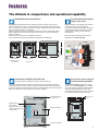
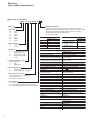
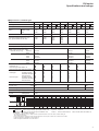
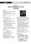
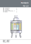
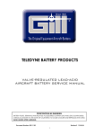
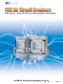
DH series New OCR providing Higher Reliability
08
EEH604b
1
■Variation
Rated current [A]
Rated Breaking capacity(kA sym.)/
Rated making current(kA peak)
IEC EN AS
[Ics=Icu]
800A
1250A
Rated Voltage
690VAC
1600A
50/105
55/121
Rated Voltage
440VAC
65/143
80/176
2000A
2500A
3200A
65/143
4000A
75/165
85/187
85/187
100/220
100/220
: DH series
: DH-H series
: DH-P series
DH-H,DH-P series : Refer to D&C catalog.
■Based Standards
IEC60947-2……………………………… International Electrotechnical Commission
EN60947-2……………………………… European Standard
AS 3947-2………………………………… Australian Standard
NEMA PUB NO.SG3…………………… National Electrical Manufactures Association
ANSI C37.13……………………………… American National Standard Institute
JIS C8372………………………………… Japanese Industrial Standards
CONTENTS
2
1. Features
3
2. Type number nomenclature
6
3. Specifications and Ratings
7
4. Combination of overcurrent tripping device and indicator
8
5. Characteristics of overcurrent trip device
10
6. Dimensions
11
7. Wiring diagrams
14
8. Accessories
16
Features
The ultimate in compactness and operational capability
Standardized basic dimenstions
Geared toward the smallest
depth in the world
The height and depth dimensions are identical in all sizes to 3200A. There are two
common widths or frame size, from 800-2000A and from 2500-3200A for the standard
series. The panel cutout size is the same for all types of DH series ACB, which makes it
easy to arrange the ACBs in switchboards.
Maximum power from minimum volume was central to the design specification. With a
depth of 290mm for the fixed type and 345mm for draw-out, it is one of the smallest
ACBs in the world.
ACBs with front connections are available off-the-shelf.
Front connections are especially suitable for smaller-depth switchboards
Direct connection of the isolating main contacts
to the hinges of the fixed main contacts
eliminates the need for intermediate conductors.
Allowing the DH series ACBs have the world’s
smallest depth resulting in space saving in
switchboards.
More than twenty design patents have been
registered for the DH series ACB.
DH Series
DB series
Saved Space
H: 460
D: 375
D: 345
W: 354
W: 460
W: 631
Standard type
800~2000A
2500~3200A
4000A
High breaking type
1250~2000A
1600~3200A
345
458
Increased accessibility from the front
It enhances ease of installation, operation, and maintenance.
The double insulated design ensures that most accessories can be safely and easily,
installed by the user. Control, auxiliary and position switch terminals are mounted at the
front on the ACB body for easy access. Due to the increased level of harmonics within the
distribution network, the neutral phase is fully rated as standard.
Connection to the
control circuit
Replacement of
internal parts
(Removing the front cover
enables replacement of
internal parts.)
No extra arc space required,
vertical stacking permitted
The DH series ACB dissipates all arc energy
within its unique “Double Break” arc chamber.
The internal energy dissipation within the ACB
allows the clearance distance of the ACB to
nearby earthed metal to be zero. This will assist
in minimizing switchboard height and costs.
No extra arc space
required
Manual operation
Draw-out operation
3
08
Features
A high performance and reliability
Very fast interruption by
“Double Break” system
No clamp screws used for the main circuit
contact units
The unique “Double Break” main contact system ensures
extremely fast interruption of short-circuit currents and substantially
reduces main contact wear. The internally symmetrical
“Double Break” structure allows reverse power connection.
There are no clamp screws or flexible leads in the main circuit
contact units.
This substantially enhances the durability of the main circuit contact
units and improves the reliability in ON-OFF operation.
Isolating main contact
Fixed main contact
Moving main contact
Enhanced selectivity
Replacement of the main contacts
The fixed and moving main contacts can easily be replaced in the field,
thus prolonging the life on the circuit breaker.
Changing each pole takes around 15 minutes.
At Fuji we are so concerned about selectivity that all our
protection relays have ‘LSI’ characteristics as standard.
This provides an adjustable time delay on overload (L) and also the
l2t ramp characteristic (S).
As shown, these are essential to provide selectivity when grading
with other protective devices such as downstream fuses and
upstream relays.
The standard ‘LSI’ curve provides more than five million
combinations of unique time current characteristics.
Zone selective interlocking is available to provide zero time delay
selectivity.
As the rated breaking capacity is identical to the rated short-time
withstand current full selectivity can be achieved.
L: Long time delay
S: Short time delay
I: Instantaneous
Performance
Rated breaking
current
(at 440V AC)
Type and rated current DH08
DH12
DH16
DH20
800A DH12H
1250A DH16H
1600A DH20H
2000A
1250A DH25
1600A DH30
2000A
2500A DH16P
3200A DH20P
DH25P
DH30P
1600A DH40
2000A
2500A
3200A
4000A
With INST trip function
With ST delay trip function
(Without INST trip/MCR functions)
65kA
80kA
85kA
100kA
100kA
Rated short-time withstand current (for 1 sec.)
Note: If the ACB is DH-H type or DH-P type without INST trip/MCR function, the rated breaking capacity will decrease down to the rated latching current.
4
For general feeder circuits (L-characteristic)
For general feeder circuits (R-characteristic)
For generator protection (S-characteristic)
Features
FUJI ACB provides positive protection for
electric power systems.
The Fuji ACB DH series is equipped with an RMS sensing over-current
release (OCR) having a wide range of protection functions and capabilities.
Optimum protective
coordination
Why use a separate panel mounted protection
relay when you can have all the benefits of
I.D.M.T. protection integral to the ACB?
Fuji ACB is available with a choice of flexible
protection curves to assist in selectivity
applications.
All these curves are user definable and comply
with IEC 60255-3. Standard transformer and
generator protection characteristics are also
available.
I 0,02 t
It
I 2 t=S.I.
3
I t=V.I.
I 4 t=E.I.
AGR-L Industrial & transformer protection
AGR-R Characteristics to IEC 60255-3
AGR-S Generator protection
Overload protection
Adjustable from 40–100% of rated current.
True r.m.s detection up to the 19th harmonic, a
distant vision for the competition who rarely
see past the 7th. Neutral protection for all
those Triple-N harmonics, such as 3rd, 9th and
15th. Also in case we forgot to mention, a
“thermal memory” as standard!
Two channel pre-trip alarm function
(S-characteristic) ✽1
This function can be used to monitor and
switch on additional power backup to feed
critical circuits. For example, the function can
be set so that when a pre-trip alarm is
activated, an emergency generator starts to
ensure a constant supply. This feature is only
available on some AGR21 OCR models with a
generator “S” characteristic.
N-phase protection function (optional)
In 3-phase, 4-wire systems that contain
harmonic distortion, the 3rd harmonic may
cause large currents to flow through the
neutral conductor. The N-phase protection
function prevents the neutral conductor from
sustaining damage or burnout due to these
large currents. Available in all OCRs except for
generator “S” characteristic types.
Inverse Definite Minimum Time (I.D.M.T.)
S.I. Standard lnverse
V.I. Very lnverse
E.I. Extremely lnverse
Standard OCR
with adjustment
dial Type AGR-11B
Reverse power trip function
(S-characteristic) ✽1
(The first-ever feature for ACBs)
This feature provides additional protection
when paralleling generators. The AGR21 OCR
for generator protection with the reverse power
trip function, negates the need for installation
and wiring in an external reverse power relay.
This feature is available using an AGR21 OCR
with a generator “S” type characteristic only.
Ground fault trip function
This function eliminates external relays to
provide a ground fault protection to TN-C or
TN-S power distribution systems on the load
side. Ground faault protection on the line side
is also available as an option.
Standard OCR
with LCD Type
AGR-21B,22B
Enhanced OCR
with LCD Type
AGR-31B
Contact temperature
monitoring function (optional) ✽2
This function monitors the temperature of the
ACBs main contacts. An alarm indicates when
the temperature exceeds 155°C. Continuous
monitoring of the contact temperature provides
valuable input for preventative and predictive
maintenance programs.
Advanced L.C.D display, Over
Current Relay
The AGR-31B OCR comes standard with an
LCD display. It can monitor and indicate phase
currents, voltages, power, energy, power
factor, frequency, and more.
✽1: Available for type AGR-22BS, 31BS.
✽2: Available for type AGR-22B, 31B OCR.
Reverse phase protection function
This function detects the negative-phase
current occurring due to reverse phase or
phase loss and precents burnout of a motor or
damage to equipment.
5
08
DH series
Type number nomenclature
■ Type number nomenclature
DH 08 3 X H - M 11BLAL F
① Basic type
② Frame size
08:
12:
16:
20:
25:
30:
40:
800A
1250A
1600A
2000A
2500A
3200A
4000A
➂ Number of poles
3:
4:
3-pole
4-pole
➃ Installation
P:
X:
Q:
Fixed (Breaking capacity
standard type only)
Draw-out with cradle
Draw-out with cradle &
shutter
➄ Interrupting capacity class
Blank: Standard
H:
High
P:
Super High
➅ Closing mechanism
T:
M:
Manual-spring
Motor-spring ex.M = 100VDC
⑦ Overcurrent release device
11BLAL:Standard (LT, ST, INST/MCA)
11BLGL:Std. Plus GF
(For details, see page 8.)
⑧ Tripping device
F: Shunt trip (AVR-1C) ex. F = 100VDC
R1: Undervoltage trip/Instantaneous (AUR-1CS)
R2: Undervoltage trip/500ms Time delay (AUR-1CD)
⑨Detailed specifications
Specify any additional requirements, such as overseas standards
compliance, special environmental usage, or accessories, when ordering.
Also clearly indicate the applicable standards, main circuit voltage,
and breaking current. See the tables below.
ex. IEC 440VAC 65kA
Applied standard
Ordering code
IEC
IEC
EN
EN
AS
AS
NEMA
NEMA
ANSI
ANSI
Special environment specification
Ordering code
Tropical uses
Tropical
Extremely cold use
Extremely cold
storage -40°C
operating -25°C
Anti-corrosion treatment Anti-corrosion
Optional accessories
Auxiliary switch (4PDT)
Auxiliary switch (10PDT)
Auxiliary switch (7PDT)
for general 4PDT, for low level circuits 3PDT
Auxiliary switch (10PDT)
for general 7PDT, for low level circuits 3PDT
OFF (Open) padlock
Automatic closing spring release device
Capacitor trip device
Control circuit safety shutter
Position switches
Test jumper
Mis – insertion protection device
Breaker fixing bolts
Door interlock
Key lock
Key interlock
Mechanical interlock
Manual reset device
IP55 cover
Control circuit terminal cover
Earthing device
Arc barrier
Door flange
Draw-out storage handle
Main circuit safety shutter
Padlocling unit for main circuit safety
shutter
Lifting plate
Ordering code
Auxiliary switch (4PDT)
Auxiliary switch (10PDT)
Auxiliary switch
4PDT + 3PDT
Auxiliary switch
7PDT + 3PDT
OFF (Open) padlock
Automatic closing spring release device
AQR-1
Control circuit safety shutter
ALR- P
Test jumper
Mis – insertion protection device
Breaker fixing bolts
Door interlock
Key lock
Key interlock
Mechanical interlock
Manual reset device
IP55 cover
Control circuit terminal cover
Earthing device
Arc barrier
Door flange
Draw-out storage handle
Main circuit safety shutter
Padlocling unit for main circuit safety
shutter
Lifting plate
External accessories
CT for neutral line 800 to 1600A frame
CT for neutral line 2000 to 4000A frame
Power transformer
Lifter
OCR checker
6
Ordering code
CW80-40LS
EC160-40LS
TSE-30M
AWR-1 (DH08 to DH30), AWR-2 (DH08 to DH40)
ANU-1
DH series
Specifications and ratings
■ Specifications, standard types
Frame size
800A
Basic type
DH08
No. of poles *
2
3
Rated current (A) *1
(Max.)
IEC, EN, AS
NEMA, ANSI
JIS
1250A
■
4
1600A
■
DH12
3
4
2000A
■
DH16
3
4
DH20
3
2500A
■
4
3200A
■
DH25
3
4
2500
2500
2500
DH30
3
4000A
■
4
3200
3200
3200
■
DH40
3
800
800
800
1250
1250
1250
1600
1540
1600
2000
2000
2000
Rated current of the neutral pole (A)
800
1250
1600
2000
2500
3200
4000
Rated primary current of
overcurrent tripping device (ICT) (A)
(For general feeder circuit use)
200
400
800
400
800
1250
400
800
1250
1600
400
800
1250
1600
2000
2500
3200
4000
4
4000
3700
3700
Rated insulation voltage (Ui) (V, 50/60Hz) *3 1000
Rated operational voltage (Ue)(V, 50/60Hz)*4
Rated breaking capacity (kA, sym.)/
Rated making current (kA, peak)
IEC, EN, AS [ICS=ICU]
690V AC
500V
690
50/105
65/143
65/143
85/187
75/165
100/220 (440V)
NEMA, ANSI
600V AC
480V
240V
42/96.6
50/115
65/149.5
50/115
65/149.5
85/195.5
65/149.5
75/172.5
100/230
JIS
550V AC
460V
220V
50/105
65/143
65/143
65/143
85/195.5
85/195.5
75/165
100/230
100/230
Installation
Fixed type P
●
Draw-out type with cradle X
●
Draw-out type with cradle and shutter Q ●
●
●
●
●
●
●
●
●
●
●
●
●
●
●
●
–
●
●
Main circuit terminal connection
Fixed type
Vertical terminal
Horizontal terminal
Front terminal
Drow-out type
Vertical terminal
Horizontal terminal
Front terminal
▲
❍
▲
▲
❍
▲
▲
❍
▲
▲
❍
▲
▲
❍
▲
▲
❍
▲
❍
▲
▲
❍
▲
▲
❍
▲
▲
❍
▲
▲
❍
▲
▲
❍
▲
▲
–
–
–
❍
–
–
Rated impulse withstand voltage (Uimp) (kV)
12
Rated short time withstand current
(Icw) (kA, rms )
1 sec. 65
3 sec. 50
85
65
100
85
Rated latching current (kA, rms )
65
85
100
Total fault clearing time (s)
0.03
Closing time
(s) max.
10
0.08
Spring charging time
Closing time
08
Dimensions(mm)
Fixed type
b
a
c
d
Drow-out type
b
a
c
d
a
b
c
d
a
b
c
d
Mass (kg) For draw-out type X
360
460
290
75
354
460
345
40
445
73
86
439
360
460
290
75
354
460
345
40
445
73
86
439
Notes: ● Available
– Not available
Replace the
mark in the type number by the pole number code
■ Replace the ■ mark in the type number by the installation code
❍ Standard
▲ Available on request
360
460
290
75
354
460
345
40
445
76
90
439
3-pole: 3
Fixed: P
360
460
290
75
345
460
345
40
445
79
94
439
466
460
290
75
460
460
345
40
586
105
125
4-pole: 4
Draw-out with cradle: X
580
466
460
290
75
460
460
345
40
586
105
125
580
–
–
–
–
631
460
375
53
139
801
176
Draw-out with cradle and shutter: Q
*1 At ambient temperature of 40°C. Rated current at standard terminal connection. Refer to D&C catalog for
other terminal connection.
*2 The 2-pole ACBs are similar to 3-pole types except that the center pole contacts and conductors are omitted.
3
* 1000V AC applies to IEC60947-2 and JIS C8201-2.
*4 690V AC applies to IEC60947-2 and JIS C8201-2.
7
DH series
Combination of overcurrent tripping device and indicator
■ Combination of overcurrent tripping device and indicator
Division
Application
Dial adjustment
type
Standard
LCD type
Enhanced
LCD type
General feeder
protection
General feeder
protection
Generator
protection
General feeder
protection
Generator
protection
Type number
LCD
*7
Multi
Amperage Long
indication indication time
delay
only
*6
LT
11BLAL
11BLGL
21BLPS
21BLPG
21BRPS
21BRPG
21BSPS
22BSPR
31BLPS
31BLPG
31BRPS
31BRPG
31BSPS
31BSPR
Protection function
Short
time
delay
Instantaneous or
Making current
release
Pre-trip
alarm
ST
INST
PTA
MCR
*5
*5
*5
*5
Note: *1 Only one function is selectable from PAT2, UV and spring charge indicator.
If you wish to select more than one function, the control circuit will be manually linked special model. Please contact FUJI.
*2 The GF function is not available when the CT rated primary current [ICT] is 200A or less.
*3 When the main circuit voltage exceeds 250V, a step-down transformer is necessary.
*4 Only one function is selectable from REF, OH, NS, and trip indicator.
If you wish to select more than one function, the control circuit will be manually linked special model. Please contact FUJI.
*5 You can select an R characteristic from the following 5 protective characteristics.
I0.02 T IT I2 T I3 T I4 T
*6 Phase current, line voltage, and power can be indicated. See page 08/65 for details.
*7 Overcurrent trip device type
*a
*b
ex. AGR - 11BL - AL-
Optional
*a AGR-11BL-AL: Overcurrent trip device only
*b 11BLAL:
ACB with the overcurrent trip device
Spring charge indication: Spring charge, Trip indication: Trip indicator
U: Undervoltage alarm
Z: Zone interlock
S: Reverse phase protection
O: Contact temperature monitoring 155°C
R: Ground fault protection on line side
N: N-phase protection
P: Pre-trip alarm 2
■ Ordering information
Specify the following:
1. Type number
2. Applied standard
3. Main circuit voltage and breaking capacity
4. Optional accessories for main device and OCR
5. Voltage of each device
6. External accessories
8
Groumd
fault
PTA2 *1 GF *2
DH series
Combination of overcurrent tripping device and indicator
:Standard
Undervoltage
alarm
Output indication
Reverse
power
N-phase Gruond
protection fault on
line side
Contact
Reverse Zone
temperature phase
interlock
monitoring protection
RPT *3
NP
OH *4
REF *4
NS *4
Single
contact
Individual Spring
contact
charge
indicator
*1
:Optional
Field test function Control power
Trip
indicator
*4
UV *1*3
Z
Not required
Not required
Required
Required
Required
Required
Required
Required
Required
Required
Required
Required
Required
Required
Note: • When AGR-11B OCR with single-contact indication is activated, the corresponding operation LED indicator is ON momentarily or OFF.
But the LED indicator is kept ON when the protection function is checked with the optional OCR checker.
• If the control power is not supplied or is lost, each function operates as follows:
LT, ST, INST, RPT
GF
MCR
PTA 1-channel
2-channel
LED indicator on OCRs with single-contact indication
Contact output from OCRs with single-contact indication
Contact output from OCRs with individual contact indication
LCD
Field test facility
Operates normally.
Operates normally
When the CT rated primary current [ICT] is less than
800 A and the GF pick-up current is set to 10 %, the
GF becomes inoperative.
Operates as INST.
Is inoperative.
Is on momentarily or off.
Turns off after 40 ms or more.
Is inoperative.
No display
Is inoperative.
08
9
DH series
Characteristics overcurrent trip device
■ Characteristics of overcurrent trip device
For general feeder circuit/L-characteristic (Type AGR-11BL, 21BL, 31BL)
Protection
function
Adjustable long time
delay trip LT
Adjustable short time
delay trip ST
Setting range
Pick-up current IR (A)
InX (0.8 — 0.85 — 0.9 — 0.95 — 1.0 — NON), 6 steps
• Non-tripping at IR X 1.05 or less • Tripping between over 1.05IR and 1.2IR or less
Time delay tR (s)
Tolerance of tR (%)
(0.5 — 1.25 — 2.5 — 5 — 10 — 15 — 20 — 25 — 30) at 600% X IR, 9 steps
±15% +150ms -0ms
Pick-up current ISd (A)
Tolerance of ISd (%)
InX (1 — 1.5 — 2 — 2.5 — 3 — 4 — 6 — 8 — 10 — NON), 10 steps
±15%
Time delay tSd (ms)
Relay time (ms)
Resettable time (ms)
Total fault clearing time (ms)
50
25
120
100
75
170
200
175
270
400
375
470
600
575
670
800, 6steps
775
870
Adjustable instantaneous Pick-up current Ii (A)
trip INST or MCR
Tolerance of Ii (%)
InX (2 — 4 — 6 — 8 — 10 — 12 — 14 — 16 — NON), 9 steps
±20%
Adjustable pre-trip
alarm PTA
In X (0.75 — 0.8 — 0.85 — 0.9 — 0.95 — 1.0), 6 steps
±7.5%
(5 —10 — 15 — 20 — 40 — 60 — 80 — 120 — 160 — 200) at IP1 or more, 10 steps
±15% +100ms -0ms
Pick-up current IP1 (A)
Tolerance of IP1 (%)
Time delay tP1 (s)
Tolerance of tP1 (%)
Adjustable ground fault Pick-up current Ig (A)
trip GF
Tolerance of Ig (%)
ICT X (0.1 — 0.2— 0.3 — 0.4 — 0.6 — 0.8 — 1.0 — NON), 8 steps
±20%
Time delay tg (ms)
Relay time (ms)
Resettable time (ms)
Total fault clearing time (ms)
100
75
170
200
175
270
300
275
370
500
475
570
1000
975
1070
2000, 6 steps
1975
2070
Ground fault trip on
Pick-up current [IREF] (A)
line side REF
Current setting tolerance (%)
(AGR-21B, 31B only) Time-delay (s)
[ICT] x (0.1 — 0.2 — 0.3 — 0.4 — 0.6 — 0.8 — 1.0 — NON), 8 steps
±20%
Inst
Neutral phase
protection
function NP
ICT X (0.4 — 0.5 — 0.63 — 0.8 — 1.0) Factory set to a user-specified value
• Non-tripping at 1.05 IN or less
• Tripping range: Between over 1.05IN and 1.2IN or less
Long time delay (LT) trip at 600% of IN
±15% +150ms -0ms
Pick-up current IN (A)
Time delay tN (s)
Tolerance of tN (%)
Reverse phase
Pick-up current [INS] (A)
protection NS
Current setting tolerance (%)
(AGR-21B, 31B only) Time-delay [tNS] (s)
Time-delay tolerance (%)
[In] x ( 0.2 — 0.3 — 0.4 — 0.5 — 0.6 — 0.7 — 0.8 — 0.9 — 1.0), 9 steps
±10%
At 150% current of [Ins], 0.4 — 0.8 — 1.2 — 1.6 — 2 — 2.4 — 2.8 — 3.2 — 3.6 — 4 , 10 steps
±20% +150ms -0ms
Undervoltage alarm
UV
(AGR-31B only)
[Vn] x (0.8 — 0.85 — 0.9 — 0.95), 4 steps
±5%
[Vn] x (0.4 — 0.6 — 0.8), 3 steps
±5%
0.1 — 0.5 — 1 — 2 — 5 — 10 — 15 — 20 — 30 — 36, 10 steps
±5% +100ms -0ms
Recovery setting voltage (V)
Recovery voltage tolerance (%)
Setting voltage (V)
Setting voltage tolerance (%)
Time delay (s)
Time delay tolerance (%)
Control power
100 to 120V AC common 100 to 125V DC common
200 to 240V AC
200 to 250V DC
)
Power consumption: 5VA
: Default setting
■
Values of [ICT] and [In] (for standard connention)
Applicable
Rated current [In](A)
[ICT]
[ICT]
[ICT]
[ICT]
[ICT]
(A)
X 0.5 X 0.63 X 0.8 X 1.0
200
DH08
100
125
160
200
400
200
250
320
400
800
400
500
630
800
400
DH12
200
250
320
400
800
400
500
630
800
1250 630
800
1000 1250
400
DH16
200
250
320
400
800
400
500
630
800
1250 630
800
1000 1250
1600 800
1000 1250 1600*
* NEMA, ANSi : Not available.
Type
: Default setting
10
Applicable
Rated current [In](A)
[ICT]
[ICT]
[ICT]
[ICT]
[ICT]
(A)
X 0.5 X 0.63 X 0.8 X 1.0
400
DH20
200
250
320
400
800
400
500
630
800
1250 630
800
1000 1250
1600 800
1000 1250 1600
2000 1000 1250 1600 2000
2500 1250 1600 2000 2500
DH25
3200 1600 2000 2500 3200
DH30
4000 2000 2500 3200 4000 *
DH40
* NEMA, ANSi, JIS : Not available.
Type
)
24V DC common
48V DC
)
DH series
Dimensions
Dimensions, mm
• Draw-out types
DH08, DH12, DH16, DH20
■
52
P
C
CONNECTED position
Control circuit terminal cover (optional)
TEST position
35
2-ø20
Conductor overlap max.
ISOLATED position
Liftin
15
Maintenance
14 21
space
hole
35
199
17
15
ON-OFF
button cover
2-ø11
138
141
345
385
265
Maintenance
space
110
40
P
C
Horizontal terminals
Rear panel cut
120
120(3P)
205(4P)
335
400
Front panel cut
BL
25
4-ø14
Mounting holes
Main circut terminal size
(t1,t2: thickness p1,p2: interphase pitch)
Horizontal terminals
Vertical terminals
p1
Type
t1
Type
t2 p2
85
DH08
10
DH20
15 85
85
DH12
10
85
DH16
20
141
Mounting holes
149
Vertical terminals
94
240
draw-out handle
94
Panel cutout
30
204
9
177(3P)
262(4P)
204(3P)
289(4P)
240(3P)
325(4P)
25
14.514.5
25 25
3-ø11
238
177
Maintenance
space
BL
33
42.5
For fitted with
breaker fixing
bolts
50
R1
16
t2
174
329
460
490
500
9
25
150.5
12
15.5
N
t1
18
15.5
25
158.5
250
164
164(3P)
249(4P)
• Fixed types
DH08, DH12, DH16, DH20
35
Conductor overlap max.
Arc barrier
Control circuit terminal
2-ø20 cover (optional)
Lifting
hole
Panel
165(3P)
250(4P)
165
365
118
Mounting holes
4-ø14
Mounting holes
550
3-ø11
100
250
30
M8 screw
earth terminal
Horizontal terminals
82
165
165
82
335
25
149
14.5 14.5
25
35
t2
238
180(3P)
265(4P)
08
Front panel cut
150.5
138
9
33
33
15
15.5
25
174
17
267
180
240(3P)
325(4P)
35
t1
199
165
P
C
12
329
329
N
460
490
550 (Arc space)
ON-OFF
button cover
240
2-ø11
15.5
25
102
18
P
175 C 175(3P)
260(4P)
52
25
15
Maintenance space
Vertical terminals
Panel cutout
Main circut terminal size
(t1,t2: thickness p1,p2: interphase pitch)
Horizontal terminals
Vertical terminals
p1
Type
t1
Type
t2 p2
85
DH08
10
DH20
15 85
85
DH12
10
85
DH16
20
11
DH series
Dimensions
■ Dimensions, mm
• Draw-out types
DH25, DH30
P
C
18
211.5
N
490
500
33
12.5
R1
16
t1
9
50
329
460
12
12.512.5
12.5
25 25 25 25 25 25
100
100
165
120
Control circuit
CONNECTED position
terminal cover (optional)
TEST position
2-ø20
ISOLATED position
Lifting Conductor overlap max.
21
Maintenance
14
hole
space
35
17
199
15
ON-OFF
button cover
60
238
265
Maintenance
space
110
4-ø11
40
P
C
Vertical terminals
Rear panel cut
94
293
draw-out handle
141
345
385
141
Mounting holes
Main circut terminal size
(thickness: 20 interphase pitch: 130)
335
Maintenance
space
9
230(3P)
350(4P)
257(3P)
377(4P)
293(3P)
413(4P)
230
257
94
400
For fitted with
breaker fixing
bolts
Front panel cut
25
172.5
172.5(3P)
250
216
Panel cutout
30
BL
4-ø14
Mounting holes
216(3P)
336(4P)
• Fixed types
DH25, DH30
Arc barrier
ON-OFF
button cover
293(3P)
413(4P)
293
102 165
Control circuit terminal cover (optional)
2-ø20 35 Conductor overlap max.
15
Lifting
hole
Front panel cut
165
217.5
12
217.5(3P)
337.5(4P)
165
365
118
335
120
550
100
100
165
4-ø11
M8 screw
earth terminal
Vertical terminals
82
233(3P)
353(4P)
35
33
33
233
82
12.5
9
Panel
252525
12.512.5
17
267
238
252525
12
329
329
460
490
N
550 (Arc space)
12.5
199
Mounting holes
4-ø14
Mounting holes
Main circut terminal size
(thickness:20 interphase pitch: 130)
250
Maintenance space
Panel cutout
100
228(3P)
348(4P)
30
P
C
18
228
DH series
Dimensions
Dimensions, mm
• Draw-out types
DH40
21
14
ON-OFF
button cover
50
2-ø20
Lifting
hole
199
12.5
18
20
329
460
490
500
12.512.5
12
N
17
For fitted with
breaker fixing
bolts
Maintenance
space
33
12.5
50
R1
16
40(Conductor overlap max.)
42.5
177
204
240
94
draw-out handle
238
481(3P)
651(4P)
9
454(3P)
624(4P)
4-ø11
141
375
428
295
25 25 25 25 25 25
100
165
120 100
Maintenance
space
435.5(3P)
605.5(4P)
15
ISOLATED position
P
C
181
Control circuit terminal cover
CONNECTED position
TEST position
15
■
35
Maintenance
space
517(3P)
687(4P)
P
C
335
141
Mounting holes
400
94
Rear panel cut
Front panel cut
4-ø14
Mounting holes
120
250
164
25
397(3P)
567(4P)
30
BL
441(3P)
611(4P)
08
Panel cutout
13
DH series
Wiring diagrams
■
Wiring diagrams(with AGR-11B OCR)
Main circuit
CT for
neutral line
Continuouslyrated
Motor charging/
Operation circuit
Operation
*1
ON switch
PB
05
S1
S3
CT1
CT3
02
12
PB
03
10
LRC
SHT
07
20
Over-current release
(type AGR-11B OCR)
M
Ry
S2
MHT
CT2
19
K
29
15
CT for
neutral line
27
22
*3
X
l
L
Symbols for accessories
Terminal description
Check OCR voltage before connecting.
02 22 Control power supply AC100 - 240V, DC100 - 250V, DC24V, DC48V
12 Operation switch, common
03 ON switch
05 Operation indication terminal, common
15 Single-contact indication
17 Trip indication
27 Spring charge indicator
10 20 Continuously-rated shunt trip
19 Separate CT for neutral line (k)
29 Separate CT for neutral line (l )
08 18 28 UVT power supply
09 UVT power supply common
UVT power supply
Term.
AC 100V AC 200V AC 400V
No.
unit
unit
unit
100V
200V
380V
08 - 09
14
17
k
18 - 09
110V
220V
415V
28 - 09
120V
240V
440V
CT1 - CT3 : Power CTs
S1 - S3
: Current sensors
M
: Charging motor
LRC
: Latch release coil
MHT
: Magnetic Hold Trigger
Isolating terminal connector
(for draw-out type)
Manual connector
User wiring
X
Relay or indicator lamp
*1: Do not connect “b”contact of auxiliary switch to ON
switch in series, otherwise, pumping may occur.
*2: See 08/57 for the circuit diagram of the continuouslyrated shunt trip device with capacitor trip device.
*3: For motor split circuit, terminals 02 , 22 and 03 , 07 are
used for charging and closing operation respectively.
(Please specify when ordering)
*4: Refer to D&C catalog (short pulse only)
*2
DH series
Wiring diagrams
Undervoltage trip
UVT power supply
08
Auxiliary switches
PB
*4
Common
09
Position switches
18
28
24
30
Basic
7PDT
151
141
131
121
111
211
311
411
Optional
3PDT
511
611
711
811
911
011
UVT control circuit
UVT
154 152 144 142 134 132 124 122
114 112 214 212 314 312 414 412 514 512 614 612 714 712 814 812 914 912 014 012
Position switches
Designation of terminals for auxiliary and position switches
* * *
1: Common
2: b-contact
4: a-contact
1: Auxiliary switch
2: Position switch (for CONNECTED)
3: Position switch (for TEST)
4: Position switch (for ISOLATED)
5: Position switch (for INSERT)
Top
151 141 131 121
Middle 154 144 134 124
Bottom 152 142 132 122
08
Operation/control circuits
01 02 03 04 05 06 07 08 09 10
11 12 13 14 15 16 17 18 19 20
21 22 23 24 25 26 27 28 29 30
Top
131 121
Middle 134 124
Bottom 132 122
numbers
( 1A,–B,0:C:Switch
Auxiliary switches for microload
CONNECTED position : 121–124 ON
121–122 OFF
TEST position
: 131–134 ON
131–132 OFF
ISOLATED position
: 141–144 ON
141–142 OFF
INSERT position
: 151–154 ON
151–152 OFF
For operation sequence of
position switches, see page 16.
Auxiliary switches
(Standard 7PDT + optional 3PDT arrangement)
111 211 311 411 511 611 711 811 911 011
114 214 314 414 514 614 714 814 914 014
112 212 312 412 512 612 712 812 912 012
(Standard 7PDT arrangement)
111 211 311 411 511 611 711
114 214 314 414 514 614 714
112 212 312 412 512 612 712
15
■
Accessories
Supplied accessories
Position switch
• Position switch ratings
Auxiliary switch (7PDT)
ON - OFF operation counter
ON - OFF button cover
Position padlock lever
Lifting hole (Draw-out type)
Draw-out handle (Draw-out type)
Voltage
100-250V AC
250V DC
125V DC
30V DC
8V DC
Resistive
load (A)
11
0.3
0.6
6
10
Inductive load (A)
(cos ø ≥ 0.6, L/R ≤ 0.007)
6
0.3
0.6
5
6
Optional accessories
• Auxiliary switch (Ratings)
Category
Voltage
100 to 250VAC
251 to 500VAC
30VDC
125 to 250VDC
For general use
Inductive load (A)
Resistive
AC: cos ø ≥ 0.3
load (A)
DC: L/R ≤ 0.01
5
5
5
5
1
1
1
1
For microload
Resistive
load (A)
0.1
–
0.1
–
Inductive load (A)
AC: cos ø ≥ 0.6
DC: L/R ≤ 0.007
0.1
–
0.1
–
Min. applicable
load
5VDC
1mA
Notes: The chattering of NC-contacts due to ON - OFF operation of the ACB lasts for less than 20ms.
Do not supply different voltages to contacts of switch.
• Auxiliary switch arrangement
For general use
4PDT
4PDT
10PDT
7PDT
■
For microload
–
3PDT
–
3PDT
Contact ratings of Trip indicator and Spring change indicator
Voltage
(V)
250 AC
250 DC
125 DC
30 DC
Switch contact ratings (A)
Inductive load
Resistive load
3
3
0.1
0.1
0.5
0.5
3
3
• Capacitor trip device
Item
Type
Rated voltage
Operational voltage
Rated frequency
Rated voltage of
shunt trip used
Power consumption
■
Specifications
AQR-1
100 to 120VAC
Rated voltage X 70 to 110%
50/60Hz
48VDC
100VA
Contact ratings other contacts
Voltage
(V)
250
250
125
30
AC
DC
DC
DC
Current (A)
Single contact
Individual contacts
Resistive load Inductive load Resistive load Inductive load
8
3
0.5
0.2
0.3
0.15
0.27
0.04
0.5
0.25
0.5
0.2
5
3
2
0.7
Type
ALR-0110P
ALR-0101P
ALR-0011P
ALR-0200P
ALR-0020P
ALR-0002P
ALR-1111P
ALR-1210P
ALR-1201P
ALR-0211P
ALR-1120P
ALR-1021P
ALR-0121P
ALR-1102P
ALR-1012P
ALR-0112P
ALR-0220P
ALR-0202P
ALR-0022P
ALR-1030P
ALR-0130P
ALR-0031P
ALR-1003P
ALR-0103P
ALR-0013P
ALR-0040P
ALR-0004P
Number of Contact arrangement
contacts INSERT ISOLATED TEST CONN
2PDT
4PDT
0
0
0
0
0
0
1
1
1
0
1
1
0
1
1
0
0
0
0
1
0
0
1
0
0
0
0
1
1
0
2
0
0
1
2
2
2
1
0
1
1
0
1
2
2
0
0
1
0
0
1
0
0
0
1
0
1
0
2
0
1
1
0
1
2
2
2
0
1
1
2
0
2
3
3
3
0
0
1
4
0
0
1
1
0
0
2
1
0
1
1
0
1
1
2
2
2
0
2
2
0
0
1
3
3
3
0
4
Safety Considerations
●
●
●
●
●
For safe operation, before using the product read the instruction manual or user manual that comes with the product carefully or consult
the Fuji sales representative from which you purchased the product.
Products introduced in this catalog have not been designed or manufactured for such applications in a system or equipment that will affect
human bodies or lives.
Customers, who want to use the products introduced in this catalog for special systems or devices such as for atomic-energy control,
aerospace use, medical use, passenger vehicle, and traffic control, are requested to consult the Fuji sales division.
Customers are requested to prepare safety measures when they apply the products introduced in this catalog to such systems or facilities
that will affect human lives or cause severe damage to property if the products become faulty.
For safe operation, wiring should be conducted only by qualified engineers who have sufficient technical knowledge about electrical work or
wiring.
5-7, Nihonbashi Odemma-cho, Chuo-ku, Tokyo, 103-0011, Japan
URL http://www.fujielectric.co.jp/fcs/eng
Printed on 100% recycled paper using soy-based ink
Information in this catalog is subject to change without notice.
16
Printed in Japan 2007-3 T 50 FIS EEH604b