1
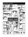
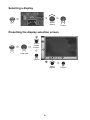
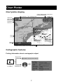
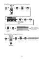
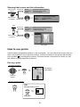
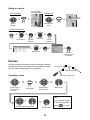
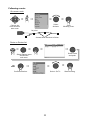
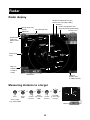
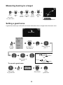
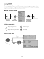
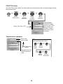
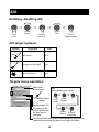
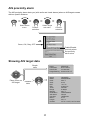
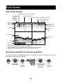
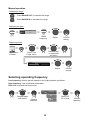
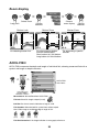
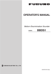
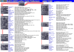
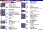
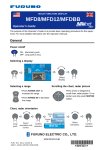
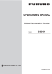
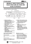
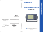
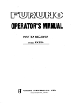
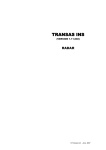
MULTI FUNCTION DISPLAY
MFDBB
User's Handbook
The purpose of this guide is to provide the basic operation for this equipment. For more
detailed information, see the Operator's manual.
All brand and product names are trademarks, registered trademarks or service marks of
their respective holders.
Table of Contents
Operating Controls ........................................................................................................ 2
How to Use the Controls ............................................................................................... 3
Using the SD Cards ...................................................................................................... 4
General ......................................................................................................................... 5
Chart Plotter .................................................................................................................. 7
Radar .......................................................................................................................... 13
AIS .............................................................................................................................. 17
Fish Finder .................................................................................................................. 19
PUB. NO. OME-44461-D
(1009, DAMI) MFDBB
Operating Controls
G
SHIP
3D
SHIP
3D
SHIP
3D
SHIP
3D
Long push
again to get
2D display
Cursor
Own ship
Moving the cursor
3D aerial view display
Momentary
push
CURSOR
Cursor moves in
direction of arrow
or diagonal pushed.
Showing the soft controls
Power on/off
ON: Momentary push
OFF: Long push (3 sec)
Finding object information
Push
Adjusting brilliance*, panel dimmer
For RotoKey
operation, see
page 3.
* For DCU12
Showing pop-up menu
Canceling entry
Rotate to adjust;
push to confirm.
Push
Place cursor with
CURSOR
CANCEL
OUT: Increase
range
OUT
Push
IN
IN: Decrease
range
Entering a point
PT-0001
MOB
Confirm.
Place cursor
with
Cursorpad.
Selecting a display
DISP
Radar
GAIN
TX
Long push
Rotate to select
display;
push to confirm.
(For details, see
page 6.)
GAIN
TX
Long push
Use Cursorpad and
left-click button ( )
to create a route.
See page 10 for
details.
Data boxes on/off
DATA
VOL
Momentary push
DATA
VOL
Adjusting audio volume
DATA
VOL
Adjust.
POINTS
ROUTE
GAIN
TX
Select HF or LF.
Toggle TX,
STBY in
radar.
Select Gain,
Sea or Rain.
Fish finder
TX, STBY
MOB mark
Momentary
push
See page 9
for details.
Creating a route
ACTIVE
Adjusting gain, sea and rain clutters
GAIN
TX
CTRL
Momentary
push
Long push
ACTIVE
CTRL
Choose
menu.
Marking MOB position
SAVE
MOB
Place cursor
with
Cursorpad.
MENU
Point
Momentary
push
Switching active display
POINTS
ROUTE
Menu operation
Saving point at current position
SAVE
MOB
.
Push to cancel
last entry.
Selecting range
RANGE
Long
push
GO TO
LIST
Centering own ship
Momentary
push
2D display
GO TO
LIST
Long push
to get 3D
display
Showing points list
Scroll the radar, chart
plotter display in the
direction of the arrow or
diagonal pressed.
OLL
SCR IN
Go to cursor location
3D display on/off
Scrolling the display (pad)
Confirm.
Long push
2
Adjust.
Confirm.
How to Use the Controls
Keys
Discrete keys provide the function(s) labeled on their keys. A key with dual functions; for example POINTS
, has a line separating the two functions. Access the top function with a momentary
ROUTE
push, the bottom function with a long push (about three seconds).
POINTS
ROUTE
Place point at
POINTS
ROUTE
cursor position.
Momentary push
Create a route.
Long push
RotoKey and soft controls
• Access by rotating or pushing
.
• They change depending on mode or function in use.
• Long push
to show full set of soft controls for current mode.
Push to show
soft controls
for current mode.
Soft
controls
(radar)
Select
soft control.
Confirm.
The cursor
The cursor mainly functions to
• measure the range and bearing to a location on the radar and chart plotter
• select position for a point and point route
It takes on one of two configurations depending on its state.
: Inactive
: Active (in motion)
3
Using the SD Cards
Care and handling of SD cards
- Handle SD cards carefully. Careless handling can damage the card
and destroy its contents.
- Ensure the lid is closed at all times.
- Remove the card with only your fingers. Do not use metallic
instruments (such as tweezers, etc.).
- Do not remove a card during either reading or writing to the card.
Inserting an SD card
1. Pull the tab on the card drive lid to open the
card drive.
2. Insert the SD card in either card drive as shown
right, with the label up. It should go in easily. If it
is doesn’t, do not try to force it.
3. Push the card until it is in place and then close
the lid.
Removing an SD card
Control Unit
MCU-001
1. Pull the tab on the card drive lid to open the
card drive.
DISP
2. Push in the card until it pops out.
GAIN
TX
MENU
OUT
3. Remove the card with your fingers and then
close the lid.
RANGE
IN
CTRL
SHIP
3D
Chart Plotter
G
OLL
SCR IN
SAVE
MOB
B RIL L
Display Control
Unit DCU12
4
General
Selecting a range
•Press RANGE OUT to increase the range.
OUT
•Press RANGE IN to decrease the range.
RANGE
IN
Scrolling the chart, radar picture
Press arrow or diagonal to scroll chart, radar picture.
SHIP
3D
G
OLL
SCR IN
Returning own ship icon to screen center
OLL
SCR IN
SHIP
3D
G
The own ship icon marks your vessel’s
position. If you can’t find it on the chart,
or you wish to re-center it on the radar or
chart plotter, push the SHIP/3D button
to return it to the screen center.
Momentary push
Chart, radar picture orientation
Chart, radar picture orientation is available in Head-up, North-up and Course-up.
Head-up: Chart with current compass heading upward.
North-up: Orientation fixed with true north upward.
Course-up: Destination is always at the screen top.
Long
push
Select
orientation soft
control.
North
Up
North Up
Course
Up
Confirm
setting.
Course Up
Head Up
5
Select
orientation.
Confirm
setting.
Selecting a display
DISP
Select
display.
Confirm.
Presetting the display selection screen
1
DISP
D
D
Select
screen
division.
D
1
Long push
2
Confirm.
2
D
Select
display.
6
Confirm.
Chart Plotter
Chart plotter display
Cursor data (postion+range and
bearing alternately)
North indicator Text message area
Sensor icons
Status bar
Chart scale,
scale reminder
Orientation
mode icon
Heading line
(green)
Direction of turn indicator (red)
SOG/COG predictor (red)
Boat icon (red)
+
Chart
(raster)
Data
boxes
Cursor*
(red)
PT-0015
Point
(black circle in
red square)
23.2 COG
°T
9.2 SOG
kt
103
DPT
m
* Inactive cursor. Active cursor looks like this
.
Cartographic features
Finding information about a cartographic object
Simple info
Buoy, lateral Phinneys Harbor Buoy 6
CURSOR
Place cursor
on object. Detailed info
7
Route
(blue: inactive
red: active)
Hiding/Showing cartographic features, text information
MENU
Select
Vector
Push
twice.
Select
Chart menu.
CANCEL
Custom
Select Custom
from pull-down
menu.
Select
Custom
Config.
Area of Shallow Depth
Rotate RotoKey to
select; push to hide
or show object.
Restoring default cartographic features
MENU
MENU
Select General,
Vector or Custom
Config.
Select
Chart menu.
8
Select this button with
RotoKey and push RotoKey.
Showing tidal current and tide information
Tidal current Simple info
marker
Name
Local Hour
Speed
CURSOR
Name
Local Hour
Speed
Source
Place cursor
on marker. Detailed info
Tide
marker Simple info
Charleston Harbor Entrance
Oct/07/07 06:54:39 AM
1.4 kt increasing
Name
Local Hour
Speed
CURSOR
Charleston Harbor Entrance
Oct/07/07 06:54:39 AM
1.4 kt increasing
NOAA
FRF Pier, Duck, North Carolina
Oct/07/07 06:51:54 AM
+0.50 m and rising
Place cursor
on marker. Detailed info
(tide graph)
Tide graph
How to use points
A point marks a geographical position on the chart plotter. You can mark points at the cursor position, ship’s position, or at a specified location. Points are marked on the screen with the waypoint symbols(
) and waypoint numbers. Points are stored in the points list, where you can
edit, delete or group waypoints as desired.
Placing a point
At cursor location
CURSOR
POINTS
ROUTE
Point marked
on chart plotter
PT 0001
Position
cursor.
At own ship's position
SAVE
MOB
TIP!
Marking MOB position
SAVE
MOB
MOB
Long push
9
Going to a point
Cursor position
set as destination
Cursor position
CURSOR
GO TO
LIST
Saved point
CURSOR
GO TO
LIST
PT 0001
Point set as
destination
Select saved
point.
Select
location.
Using the points list
MENU
Select
Points menu.
Confirm
selection.
Select
Alpha list.
Confirm
selection.
Select point.
Go To is
selected; push
to confirm.
Routes
A route consists of a series of points leading to ultimate
destination. Routes are stored in the Routes list, where
you can edit or delete routes as necessary.
Route point
Route legs
Course to 1st point
Creating a route
CURSOR
Place cursor
on 1st point
of route.
URSOR
CUCRSOR
POINTS
ROUTE
Long push
CURSOR
CURSOR
Drag cursor
to next point.
Mark point.
Tip!
+
CURSOR
Place remaining points.
If you marked a point
at the wrong position
press CANCEL to undo.
Save route.
10
Following a route
On-screen route
CURSOR
Choose leg
from where to
start route.
Select
Activate.
Flyover
Start
following route.
1st point
Arrows show direction to follow.
Route on Routes list
MENU
Select route
and push.
Select Routes menu
and Routes
sub menu.
Confirm selection.
Select Go To.
11
Start following.
Radar
Radar display
Window for adjustment of gain,
sea and rain (normally hidden)
Heading
Cursor data (position and
range and bearing alternately)
Range, range ring
interval
Text message area
Status bar
Presentation
mode icon,
Motion mode
icon
Sensor icons
Guard
zone
North
marker
Heading
line
EBL1
VRM1
+
Fixed range
rings
Bearing
scale
Own ship
icon
VRM2
EBL2
EBL box
(hidden when
no EBL is
active)
Cursor
Data boxes
VRM box
(hidden when
no VRM is active)
Measuring distance to a target
Target
VRM1
+
VRM2
Push*
Select
VRM.
Select
Confirm appropriate
selection.
VRM.
Set VRM
Confirm on inner edge
selection.
of target.
*Short: VRM1
Long: VRM1/VRM2
Check VRM box for range.
VRM 1
2.434 nm
VRM box VRM 2 6.308 nm
12
Measuring bearing to a target
153
EBL2
+
EBL1
Select
EBL.
Push*
Select
Confirm appropriate
selection.
EBL.
Confirm
selection.
Bisect
target with
EBL.
*Short: EBL1
Long: EBL1/EBL2
Target
Check EBL box for bearing.
EBL 1 210.2 °T
EBL 2 59.4 °T
EBL box
Setting a guard zone
A guard zone alerts you with audio and visual indications when a target enters the alarm zone.
153
Guard Zone
CURSOR
Select
Set Guard 1 or
Set Guard 2.
On radar
screen
CURSOR
CURSOR
CURSOR
Place cursor at
point 1.
Point 1
Point 2
OR
Place cursor at
point 2.
Point 2
Point 1
To cancel a guard zone:
CURSOR
Select
Clear Guard.
Place cursor
on guard zone.
13
Erase
guard zone.
Using ARPA
The Automatic Radar Plotting Aid (ARPA) is a radar function for target tracking and collision
avoidance. ARPA tracks and provides detailed information for up to 30 targets. You can track
targets automatically, manually or a combination of both.
Manually acquiring a target
Place cursor
on target.
Show
Radar popup.
Acquire Target
is selected;
push RotoKey.
ARPA target symbols
: Target being acquired.
: Acquired target.
: Target data being calculated.
: Lost target.
Showing target data
ID
COG/SOG
CPA/TCPA
Range/Bearing
Simple
data
1
56.2°T/6.8 kt
3 m/55m03s
6.366 nm/26.7°T
CURSOR
CURSOR
Place cursor on
ARPA target.
Detailed
data
14
ID
COG
SOG
CPA
TCPA
Range
Bearing
Position
1
56.2°T
6.8 kt
3m
55m03s
6.366nm
26.7°T
34°37.1715'N; 135°10.2459
CPA/TCPA alarm
The CPA/TCPA alarm alerts you (with audio and visual alarms) when a tracked target violates
the selected limits.
MENU
Select
Alarm menu.
Confirm
selection.
Select
Target
sub menu.
Confirm
selection.
Enable/Disable
CPA/TCPA alarm.
Set CPA and TCPA
alarm values with
RotoKey; rotate to
select value, push
to confirm.
Green, ON, Gray, OFF
Exit Menu
Targets menu operation
Select track
history length.
TIP!
Showing/hiding track history
Track history
display
Use guard zone as
ARPA acquisition
area.
Long
push
Select
Targets.
Select
Push to
History. show/hide.
15
AIS
Enabling, disabling AIS
Long
push
Select
Targets.
Select
AIS.
Confirm
selection.
Push to
enable/disable.
AIS target symbols
Symbol
COG
Target type
Color
AIS target
Blue
Dangerous AIS target
Red
Lost AIS target
Blue
Targets menu operation
Green, ON, Gray, OFF
Select track
history length.
TIP!
Showing/hiding track history
Track history
display
Display targets' IDs.
AIS targets at distances greater than
set here are not
displayed.
Long
push
Select
Targets.
Select
Push to
History. show/hide.
AIS targets within the proximity AIS target alarm range whose
speeds are slower than set here do not trigger the alarm.
16
AIS proximity alarm
The AIS proximity alarm alerts you (with audio and visual alarms) when an AIS targets comes
within a specific distance.
MENU
Select Alarm
menu.
Confirm
selection.
Select Target
sub menu.
Confirm
selection.
Green, ON, Gray, OFF
Enable/Disable
proximity alarm.
Set proximity
alarm value.
Showing AIS target data
Simple
data
CURSOR
CURSOR
Place cursor on
AIS target.
Detailed
data
17
Name
COG/SOG
CPA/TCPA
Range/Bearing
PEGASUS
56.2°T/6.8 kt
3 m/55m03s
6.366 nm/26.7°T
Name
MMSI
COG
SOG
ROT
CPA
TCPA
Range
Bearing
Destination
AIS Status
Call SIgn
Beam
Length
Position
VOYAGER
MSN3456098
56.2°T
6.8 kt
+0.7°/m
0.8593 nm
23m08s
6.366nm
26.7°T
NISHINOMIYA
Normal
HQZE4509
8.0 m
30.1 m
34°37.1715'N; 135°10.2459
Fish Finder
Fish finder display
Water temperature scale and graph*
Text message area
Minute marker
(dark yellow
and white
alternately,
30 s each)
Elapsed time (from right edge to vertical line)
Zero line (reddish brown)
Sensor icons
Status bar
Frequency
selector icon
Gain adjustment
window
(normally hidden)
Color bar
Depth scale
VRM
Fish symbol**
34
Bottom echo
Depth
Data boxes
* Requires water temperature sensor.
**ACCU-FISH feature estimates length of individual fish.
(Requires appropriate transducer and Bottom Discrimination Sounder BBDS1,
Network Sounder DFF1 or DFF3, or Color LCD Sounder FCV-1150.)
Selecting automatic or manual operation
Your fish finder can be operated automatically or manually. In automatic operation, range, gain
and clutter are automatically adjusted.
Select Auto
soft control.
Fishing
Cruising
Off
Confirm
selection.
18
Choose Fishing
or Cruising for
Auto; Off for
Manual.
Confirm
selection.
Manual operation
Selecting a range
OUT
- Press RANGE OUT to increase the range.
RANGE
IN
- Press RANGE IN to decrease the range.
Adjusting the gain
GAIN
TX
0%
0%
GainHF
GainLF
GAIN
TX
Select
frequency.
Adjust.
Confirm
setting.
Rejecting clutter
Appearance
of clutter
MENU
Select Clutter
on applicable
sub menu.
Select Fish
Finder menu.
Clutter
27 %
Adjust.
Confirm
setting.
Selecting operating frequency
Low frequency: Use for general detection and judging bottom conditions.
High frequency: Use for detailed observation.
Dual: Both high and low frequencies.
Choose Mode
soft control.
HF
LF
Confirm
selection.
Dual
19
Select HF,
LF or Dual.
Confirm
selection.
Zoom display
Select Zoom.
Choose
zoom display.
Confirm
selection.
Long push
Bottom Lock
Bottom Zoom
0
0.0
0.0
0
0
15
20
20
20
10
10
10
40
5
60
For detecting bottom fish.
45.2
20.0
40
40
5
45.4 ft
Confirm
selection.
Marker Zoom
15
15
5
ft
60
45.4 ft
60
For expanding a specific
For discriminating bottom
location.
fish from bottom echo.
Short bottom tail: Soft bottom
Long bottom tail: Hard bottom
ACCU-FISH
ACCU-FISH measures the depth and length of individual fish, showing measured fish with a
symbol and length or depth indication.
MENU
ACCU-FISH
menu items
Select
Fish Finder menu
and DFF1/BBDS1 /
DFF3/FCV sub menu.
Measurement: Activate/Deactivate ACCU-FISH.
15
Fish Info: Show fish length or depth (in red).
Info Size: Set size of numeric indication to large or small.
Fish Symbols: Select desired fish symbol from solid or striped.
Size is either large or small depending on length of fish.
15
Solid
(Small)
60
Solid
(Large)
15
Striped
(Small)
60
Striped
(Large)
Fish Size Correction: If the length indication is wrong apply offset here.
20