1
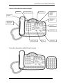
Commander Connect Getting Started Guide
Table of Contents
GUIDE TO SYSTEM DOCUMENTATION............................................................................................... 3
Getting Started Guide.......................................................................................................................... 3
Keystation Quick Reference Guide ................................................................................................... 3
Owner Manual ...................................................................................................................................... 3
Internet Module Manual ...................................................................................................................... 3
Documentation CD .............................................................................................................................. 3
SYSTEM DESCRIPTION ........................................................................................................................... 4
System Options.................................................................................................................................... 4
System Support.................................................................................................................................... 4
System Programming Notes .............................................................................................................. 4
Guide to Standard Keystation layout ................................................................................................ 5
Explanation of Symbols in this Guide ............................................................................................... 6
SYSTEM PROGRAMMING ....................................................................................................................... 6
Accessing the System Programming ................................................................................................ 7
PROGRAMMING SYSTEM TIME & DATE............................................................................................. 8
CONFIGURING A GROUP (RING/HUNT GROUP)............................................................................... 9
Configuring Group & Assigning Stations .......................................................................................... 9
Note on Groups & Group Types ...................................................................................................... 10
Groups................................................................................................................................................. 10
Note: Group Programming ............................................................................................................... 10
Note: Group Names........................................................................................................................... 10
Configuring Group & Assigning Stations [continued] ................................................................... 11
Mapping Incoming Calls to a Group [From a Network Line]........................................................ 12
Note on Incoming Call Mapping....................................................................................................... 12
Mapping Incoming Calls to a Group [From an MSN or DDI] ....................................................... 13
CONFIGURING CALL BARRING RULES............................................................................................ 14
Call Barring and Tables .................................................................................................................... 14
Setting up Call Barring Tables ......................................................................................................... 15
Assigning rules to Stations ............................................................................................................... 16
CONFIGURING NIGHT & WEEKEND SERVICE ................................................................................ 17
SYSTEM PASSWORD ............................................................................................................................. 18
Changing System Password ............................................................................................................ 18
Examining Station Passwords ......................................................................................................... 18
VOICEMAIL................................................................................................................................................ 19
Configuring Answering Machine...................................................................................................... 19
Enabling Answering Machine........................................................................................................... 19
Assigning Voice Mail Stations.......................................................................................................... 20
Assigning Voice mail Capacities...................................................................................................... 20
SPEED DIALS ........................................................................................................................................... 21
Programming Personal Speed Dials............................................................................................... 21
1
Commander Connect Getting Started Guide
Programming System Speed Dials ................................................................................................. 22
POWER FAIL OPERATION .................................................................................................................... 23
Analogue Systems............................................................................................................................. 23
Digital Systems................................................................................................................................... 23
Battery Backup Unit........................................................................................................................... 23
STATION SETTINGS ............................................................................................................................... 24
Station Name & Settings................................................................................................................... 24
Additional Station Settings................................................................................................................ 25
CONFIGURING THE INTERNET MODULE ......................................................................................... 28
ADSL Service ..................................................................................................................................... 29
ISDN Service ...................................................................................................................................... 29
2
Commander Connect Getting Started Guide
Guide to System Documentation
The Commander Connect is provided with the following range of documentation:
Getting Started Guide
Provides overview of System Programming and Key Features
The Getting Started Guide takes the user through key system programming and enables the
user to modify basic system configurations to suit their business requirements. In addition, it
allows an appointed ‘Administrator’ to configure the system, through key settings and
programming elements, enabling a tailored business solution.
Keystation Quick Reference Guide
Provides Quick Reference to Key System Features
The Quick Reference Guide’s are supplied with each Commander Connect keystation as an
easy to view fold out for each system user. Also provided is a simple reference to the key
operation and system features of Keystations or Standard Telephones.
Owner Manual
Provides complete detail on System Programming and Features
The Owner Manual is provided with each Commander Connect System, covering System
Programming, Administration and Usage, and providing the appointed ‘Administrator’ with
information on configuration of advanced system features.
Internet Module Manual
Provides complete detail on Internet Module Programming and Usage
The Internet Module Manual is provided with each Commander Connect system, covering
System Programming, Administration and Usage, and provides the appointed “administrator”
with information of configuration of advanced system features.
Documentation CD
Contains PDF files of the Getting Started Guide, Owner Manual, Standard keystation Quick
reference Guide, Executive keystation Quick reference Guide, Internet Module Manual and
personal Keystation label templates.
3
Commander Connect Getting Started Guide
System description
•
The Commander Connect is an Integrated Communications System. It supports all your
voice call needs and an Optional integrated Data Solution that allows multiple simultaneous
Internet sessions.
•
The Commander Connect can accommodate up to 16 Analogue Lines, 8 ISDN Basic Rate
Accesses, or a combination of both, with up to 32 Stations maximum.
System Options
Your Commander Connect may be delivered or installed with additional optional components,
or you may choose to purchase them. The following options are available:
•
Additional Station Modules each containing 8 extra station ports.
•
Additional Digital or Analogue Line Modules to a maximum of 16 lines
•
Optional Internet Module for shared High Speed Internet Connections
•
Optional Voice Mail Module for professional voice services
•
Optional Battery Back Up Module for full system operation in power fail
•
Options Module for connecting Long Line Station, External Music on Hold or Central Bell.
•
Standard Keystation with full Menu Display, Handsfree Operation and 8 Programmable
keys
•
Executive Keystation with full Backlit Menu Display, Handsfree Operation and 16
Programmable keys. Console providing an additional 32 Programmable Keys when used in
conjunction with the Executive Keystation
•
Door Station to facilitate visitor introduction
System Support
Commander Support Web site
www.commander.com
Connect Support email
[email protected]
Commander
132 777
System Programming Notes
The Commander Connect may be programmed from either a Standard / Executive Keystation
or from the OVIDA PC Configuration Tool supplied on the CD-supplied with your system. This
guide outlines the key elements of System Programming from the Keystations only.
4
Commander Connect Getting Started Guide
Guide to Standard Keystation layout
Mute Key
Hands Free Key/Light
Volume Keys
Handpiece
4 Function Keys:
Program
Message
Directory
Network
Message
Waiting/Ringing
Indicator
Data Socket and
Headset Socket
(underneath)
Display Keys
Scroll/Edit Keys
Numeric Keypad
C Key
Scroll/Edit Keys
Executive Keystation (with 32 key Console)
5
Commander Connect Getting Started Guide
Explanation of Symbols in this Guide
Specific symbols are used to define particular operations or to highlight important areas as
follows:
Caution
Programming Key
Select Function
Scroll through Menus
System Programming
The System may only be programmed from one specific station, by default this is configured as
Station 20, but the programming position may be moved to any Station required.
The System Programming is separated into 3 main blocks:
System
covers aspects that affect operations across the complete system
Station
covers aspects that may be programmed per station
Lines
covers aspects which affect the Network connections, Incoming and Outgoing
Calls, and Least Cost Routing configuration.
6
Commander Connect Getting Started Guide
Accessing the System Programming
Instruction
Action
Menu Display
From the Programming Position
(Stn. 20 by default) select the
Programming Key
---Phone Setup---Auto Answer
-Key Programming
-Headset Mode
Scroll through the menus to find
[System Programming] and select
the option
---Phone Setup---Ringing Options
-Contrast Options
-System Programming
Enter Password
1111 (default)
You are now in the Main Menu for
System Programming and are
presented with the following Sub
Menus for Programming Options
-Enter System Password
-Exit
Select Option
-System
-Stations
-Lines
The remainder of this document assumes that you have successfully
navigated to the System Programming Sub Menu above.
C
Depress the
key for 2 seconds at any time or Hang Up to
exit the Programming mode at any time. Modified settings are SAVED
automatically.
For more complex settings please refer to the Owners Manual provided
on the CD-ROM packaged with your system.
7
Commander Connect Getting Started Guide
Programming System Time & Date
Instruction
From the System Programming
Sub Menu Select [System]
Select [Time & Date]
Enter Time [HHMM]
Enter Date [DDMMYY]
Action
Menu Display
Select Option
-System
-Stations
-Lines
Select Option
-Time and date
-Change password
-Programming position
Set Time HHMM
-Confirm
- Exit
Set Date DDMMYY
-Confirm
-Exit
Note: Time and date Settings are saved automatically, you are then returned to the Main
Programming Menu.
8
Commander Connect Getting Started Guide
Configuring a Group (Ring/Hunt Group)
Configuring Group & Assigning Stations
Instruction
Action
Menu Display
Select Option
-System
-Stations
-Lines
From the System Programming
Sub Menu Select [Lines]
Select Option
-Equipped Lines
-Group Programming
-Incoming Ringing
Select
[Group Programming]
Select the Group to be Programed
[Scroll If Necessary]
Scroll
Select Group
◊ Group 1
◊ Group 2
◊ Group 3
Group 4◊
Group 5◊
Group 6◊
[To Select a group(s) select
the diamond next to it ]
Select the Group type to be
programed
Select Group Type
-Ring Group
-Hunt Group
-Exit
9
Commander Connect Getting Started Guide
Note on Groups & Group Types
Groups
Note: Group Programming
When assigning Stations within a Ring or Hunt Group the first 8 stations are included by
default in Group 1. The administrator may select or deselect Stations within a Group at
any time.
Note: Group Names
All Groups can be assigned specific names to facilitate ease of programming and system
usage. Please refer to the section on Naming in this document for instructions on creating
Group or Station names.
Groups of different types may be configured in your Commander Connect System. When
programming a Group you will be offered the following options:
Ring Group:
When selected all phones in the Group ring simultaneously for an incoming
call
Hunt Group: When selected incoming calls are presented to one phone only within the
group and the calls are filtered through the various Stations as follows:
• Linear
Calls are presented to the lowest numbered station first. If a station is busy the
call is presented to the next free station.
• Circular
Calls are presented in strict rotation starting with the lowest numbered station in
the Group (i.e. Call 1 is presented to Station 20, call 2 to Station 21 etc.)
• Longest Idle
Incoming calls are presented to the station that has been idle for the longest
period of time
10
Commander Connect Getting Started Guide
Configuring Group & Assigning Stations [continued]
Instruction
Action
Menu Display
If RING GROUP is selected
Select the Stations to be included in
the RING GROUP
Scroll
Select Stations
◊ Stn. 20
Stn. 23◊
◊ Stn. 21
Stn. 24◊
◊ Stn. 22
Stn. 25◊
[To Select a station(s) select the
diamond next to it ]
If HUNT GROUP is selected
Select the HUNT GROUP type
required
(See Previous page for Notes on
Group Types)
Select the Stations to be included in
the HUNT GROUP
Select Hunt Group Type
◊ Linear
◊ Circular
◊ Longest Idle
Select Stations
◊ Stn. 20
Stn. 23◊
◊ Stn. 21
Stn. 24◊
◊ Stn. 22
Stn. 25◊
[To Select a station(s) select the
diamond next to it ]
11
Commander Connect Getting Started Guide
Mapping Incoming Calls to a Group [From a Network Line]
Instruction
Action
Select Option
-System
-Stations
-Lines
From the System Programming
Sub Menu Select [Lines]
Select Option
-Equipped Lines
-Group Programming
-Incoming Ringing
Select
[Incoming Ringing]
Select the Line or Access for which
this rule applies
Menu Display
Scroll
Select the time when this rule
should apply
Select the Destination for Incoming
Calls on this Line or Access [ Group
In This Case]
Select the Group which is to receive
Incoming Calls on this Line or
Scroll
Access during the relevant Time
Period
Select Line
-Line 1
-Line 2
-Access 2
-Door Station
Select Option
-Day Mode
-Night Mode
-Day and Night Mode
Select Destination
-Station
-Group
◊ Auto Attendant
Select Group
◊ Group 1
Group 4◊
Group 5◊
◊ Group 2
◊ Group 3
Group 6◊
[To Select a group(s) select the
diamond next to it ]
Note on Incoming Call Mapping
You may map Incoming Calls on Specific Lines to be presented to different Groups in Day and
Night Mode
12
Commander Connect Getting Started Guide
Mapping Incoming Calls to a Group [From an MSN or DDI]
Instruction
Action
Select Option
-System
-Stations
-Lines
From the System Programming
Sub Menu Select [Lines]
Select Option
-CLI Programming
-DDI Programming
-PSTN Programming
Scroll down and select
[DDI Programming]
Enter MSN Index 001 – 100
Menu Display
Scroll
XXX
Enter MSN Index
- Exit
May be Existing or New
Enter MSN/DDI Number
XXXXXXXXX
May be Existing or New
Confirm when complete
Enter MSN Name
May be Existing or New
Confirm when complete
Select the time when this rule
should apply
Select the Destination for Incoming
Calls on this MSN or DDI
Select the Group that is to receive
Incoming Calls on this MSN or DDI
Number during the relevant time
period.
ABCDEFGHIJ
-------------Confirm
-Change
-Delete
Exit-
-------------Confirm
-Change
-Delete
Exit-
Select Option
-Day Mode
-Night Mode
-Day and Night Mode
Select Destination
-Station
-Group
◊ Auto Attendant
Select Group
◊ Group 1
Group 4◊
♦ Group 2
Group 5◊
◊ Group 3
Group 6◊
[The selected group is indicated by
‘♦ ]
13
Commander Connect Getting Started Guide
Configuring Call Barring Rules
Call Barring and Tables
Call Barring allows you to prevent specific stations making specific types of calls in Day or
Night Mode. To configure Call Barring Rules you first set up the rules [CLASS CODES]as
described below and then assign the relevant rules to individual stations.
There are four Tables which may be programed and six [CLASS CODES] which may be
assigned to a station as listed below.
Type of Restriction
Table
CLASS
Typical
Use
No restriction
None
1
None
Restricted from calls in Table 2
2
2
Bar 00
Restricted from calls in Table 2 & 3
3
3
Bar 0
Allowed Internal and Emergency Calls only
None
4
Bar ALL
Allowed Numbers that overide Table 2 & 3
Allowed
5
Exception
Restricted
6
Specific Bar
Restricted Numbers that overide Table 1, 2 & 3
Table
Bar
Default settings
Table 2
International
None
Table 3
National
None
14
Commander Connect Getting Started Guide
Setting up Call Barring Tables
Instruction
Action
Select Option
-System
-Stations
-Lines
From the System Programming
Sub Menu Select [System]
Scroll down and select
[Class Codes]
Menu Display
Select Option
-Class Codes
-Reset Options
-Set v24 Baud Rate
Scroll
Select Table
-Table 2
-Table 3
-Allowed Table
-Restricted Table
Select the Table which is to be
programmed
Enter Index 01 – 50
May be Existing or New Index
Select Confirm to Complete the SetUp
[See Note Below for ‘ANY’ Option]
XX
Enter Index 01 - 50 - Enter the
number or code you wish to bar
here
-Exit
Select Option
-Any
-Confirm
-Change
Note: Each entry restricts or allows one number or range of numbers. A wildcard may be used
‘ANY’ (i.e. 403 X would bar calls to numbers between 403-1 and 403-9.
15
Commander Connect Getting Started Guide
Assigning rules to Stations
Instruction
From the System Programming
Sub Menu Select [Station]
Select
[Restriction Classes]
Select the time for rule to be applied
Day or Night
Select the Class Rule to be applied
Class 1 to 6
Select the Stations to which this rule
applies
Action
Menu Display
Select Option
-System
-Stations
-Lines
Select Option
-Name Programming
-Restriction Classes
-Tone Protect
Select Option
- Day Class of Service
- Night Class of Service
- Exit
Select Option
-Class 1
-Class 2
-Class 3
Class X day/night
♦ Stn. 20
Stn. 23◊
◊ Stn. 21
Stn. 24◊
◊ Stn. 22
Stn. 25♦
[The selected station is indicated
by ‘♦’ ]
Note: You may apply the same rule to multiple stations
You may apply multiple rules to the same station
You may exit the menu at any time and the settings will be saved
16
Class 4Class 5Class 6Exit-
Commander Connect Getting Started Guide
Configuring Night & Weekend Service
Instruction
From the System Programming
Sub Menu Select [System]
Scroll down and select
[Night Service]
Menu Display
Action
Scroll
Program Night Service On & Off
Times
[Apply Weekend (if required)]
Select the required On Times
Enter Time to be set and then select
Confirm
Select the required Off Times
Enter Time to be set and then select
Confirm
Select Option
-System
-Stations
-Lines
Select Option
-Night Service
-Music on Hold
-Line Key Light
Select Option
-Automatic On Times
-Automatic Off Times
-Weekend Service
Select Option
-On Time 1
-On Time 2
-Exit
Set Time [HHMM]
-Confirm
-Change
-Delete
Select Option
-Off Time 1
-Off Time 2
-Exit
Set Time [HHMM]
-Confirm
-Change
-Delete
Note:
You may apply 2 sets of times for the Night Service rules to be applied, typically this will be used
for Lunch Time and Out of Office Hours.
Night Service allows you to configure different call routing plans for these time periods.
You may exit the menu at any time and the settings will be saved
17
Commander Connect Getting Started Guide
System Password
Changing System Password
Instruction
Action
Menu Display
Select Option
-System
-Stations
-Lines
From the System Programming
Sub Menu Select [System]
Select Option
-Time & Date
-Change password
-Programming position
Select
[Change Password]
1111
-Confirm
-Change
-Exit
Enter New Password [xxxx]
4 digit numeric and Confirm
Examining Station Passwords
Instruction
Action
From the System Programming
Sub Menu Select [Station]
Scroll down and select
[Exaime Passwords]
Scroll
Select the password which you
need to view
The Answering Machine password
is displayed immediately. For other
options you will be prompted to
select the station to view
Note: The '♦' next to a station
indicates a voice box is enabled for
that station.
18
Menu Display
Select Option
-System
-Stations
-Lines
Select Option
-No Call Logging
-External Diversions
-Examine Passwords
Select Option
-Stn. Lock Password
-Voice Mail Password
-Answering Machine
Select Station
♦ Stn. 20
Stn. 23◊
♦ Stn. 21
Stn. 24◊
Stn. 25◊
◊ Stn. 22
[To Select a station(s) select the
diamond next to it ]
Commander Connect Getting Started Guide
Voicemail
Configuring Answering Machine
NOTE: To utilise the Voicemail features on the Commander Connect, you must purchase and
install the optional Voicemail module
Instruction
Action
Select Option
-System
-Stations
-Lines
From the System Programming
Sub Menu Select [Lines]
Select Option
-Outgoing line priority
-PABX group
-Answering Machine
Scroll down and select
[Answering Machine]
Menu Display
Scroll
Answering Machine
◊ Access 1
◊ Line 1
◊ Line 2
[The selected lines are indicated
by a ‘♦’]
Select the Line(s) which are to be
answered by the System Answering
Machine when it is enabled
Enabling Answering Machine
Instruction
From Station 20 in idle menu Scroll
down and select
[Answering Machine]
Action
Menu Display
Select Option
-Night Service
-Answering Machine
-Divert
The keystation’s display will show ‘Answering Machine On’ for approx 2-3 secs and will return to
the idle display
19
Commander Connect Getting Started Guide
Assigning Voicemail Stations
NOTE: To utilise the Voicemail features on the Commander Connect, you must purchase and
install the optional Voicemail module
Instruction
Action
Select Option
-System
-Stations
-Lines
From the System Programming
Sub Menu Select [Stations]
Select Option
-Individual CLI Stores
-System Speed No Override
-Voice Boxes
Scroll down and select
[Voice Boxes]
Menu Display
Scroll
Select Station
♦ Stn. 20
Stn. 23◊
◊ Stn. 21
Stn. 24◊
♦ Stn. 22
Stn. 25◊
[To Select a station(s) select the
diamond next to it ]
Select the Stations which are to be
assigned individual Voicemail
Boxes
Assigning Voicemail Capacities
NOTE: The system assigns a limit of 20 Messages per Voicemail Box, this may be modified if
required as follows.
Instruction
Action
From the System Programming
Sub Menu Select
[System]
Scroll down and select
[System VM Capacity]
Scroll
Enter the required number of
messages allowed per station
20
Menu Display
Select Option
-System
-Stations
-Lines
Select Option
-Commander
-VM Capacity
-Account Codes
Enter VM Cap. 10-50
-Exit
Commander Connect Getting Started Guide
Speed Dials
Programming Personal Speed Dials
NOTE: Speed Dial Numbers may be entered from any station, however the entry of System
Speed Dial numbers is password protected with the Administrator Password.
Instruction
From your keystation
Select the Directory Key
Select
[Personal Entries]
Enter the Speed Dial number index
to modify an existing entry or a new
index to create a new entry
You enter the number and
press’Confirm’
Action
Menu Display
--Directories--Personal Speed Dial
-System Speed Dial
-Personal Entries
Enter spd index 01-30
- Personal Entries
Enter SPD number
1. Enter Number
2. Enter Name
3. Confirm
Enter the name and press ‘Confirm’
21
Commander Connect Getting Started Guide
Programming System Speed Dials
Instruction
From your Keystation
Select the Directory Key
Scroll and Select
Action
Menu Display
--Directories--Personal Speed Dial
-System Speed Dial
-Personal Entries
-System Entries
Enter system Password
[System Entries]
Enter the Speed Dial number index
to modify an existing entry or a new
index to create a new entry
Enter SPD Index 001-500
1. Enter Number
2. Enter Name
3. Confirm
Enter the number and press
‘Confirm’
Enter the name and press ‘Confirm’
Select the outgoing group (normally
the first group
22
♦ Outgoing group
◊ Outgoing group 2 (760)
◊ Outgoing group 3 (761)
Commander Connect Getting Started Guide
Power Fail Operation
Your Commander Connect is provided with a basic power fail mechanism to allow the system
to continue operation in power fail situations.
Analogue Systems
For systems with traditional Analogue (PSTN) Lines 2 stations on each station module are
connected directly to the first 2 Network Lines on that module as follows:
Table 1
Lines
1/2
5/6
9/10
13/14
Station
26/27
34/35
42/43
50/51
Digital Systems
Systems populated with Digital (ISDN) Lines only will not operate in Power Fail mode. These
systems MUST be installed with the Optional Battery Back Up unit or an auxiliary
uninterruptible Power Supply (UPS)
Battery Backup Unit
The Optional BBU available with the Commander Connect will ensure all system configurations
can operate to full capacity for a minimum of 1 hour under normal load conditions.
23
Commander Connect Getting Started Guide
Station Settings
Station Name & Settings
NOTE: Each Station on the Commander Connect System may be configured with different
settings. This section describes how to change the Station names and list the key settings that
may be configured. Please refer to the full User Manual for further instructions if required.
Instruction
From the System Programming
Sub Menu Select
[Station]
Select
[Name Programming]
Select the required Station and
enter the name required and press
‘Confirm’
Action
Menu Display
Select Option
-System
-Stations
-Lines
Select Option
-Name Programming
-Restriction Classes
-Tone Protect
Select Station
◊ Stn. 20
◊ Stn. 21
◊ Stn. 22
Stn. 23◊
Stn. 24◊
Stn. 25◊
[To Select a station(s) select the
diamond next to it]
24
Commander Connect Getting Started Guide
Additional Station Settings
See the table below for a full range of settings. The following parameters may be also be set on
a station by station basis. Refer to the full ‘User Manual’ for detailed programming instructions if
required.
25 Hz
This allows the ringing frequency to be changed from 25 to 50 Hz.
The default setting is 25Hz however some older phone equipment
may require 50 Hz for ringing. This setting should only be applied if a
telephone does not ring correctly at 25 Hz.
Allows an outgoing call to be set for 3.1Khz minimum bandwidth. It is
advisable to set this for Fax or Modem calls out over ISDN lines
Removes an unpopulated station from all ring maps
Station Disconnect
Allows a station to be set to call a pre-programmed number when the
Hot Line
station goes off hook. Typically used for unsupervised reception
areas or fax machines
Individual CLI Stores The administrator can decide which stations have individual CLI
stores
Allows the keypad tones to be switched on/off on a station by station
Key Pad Feedback
basis.
Allows specific features to be mapped between a manager and
Manager/Secretary
secretary for improved functionality
Prevents calls to or from this station from being stored in the system
No Call Logging
call logging information
This prevents or allows stations from setting up diverts externally and
External Diversions
also prevents a station from making dual trunk calls, such as
External Transfer, Conference or Consultation
Open Door Restriction A station can be restricted from Opening the Door if a remote door
opening system is installed
Removes a station from the paging group
Page Protect
Allows a station to be set so that it never sends the CLI number
Permanent CLIR
when making an outgoing call (CLIR)
Allows a station to be set so that it never shows the CLI number
Permanent COLR
during a connected incoming call (COLR)
Allows 2 stations to be swapped on the system for administration or
Port Swapping
programming purposes
Prevents a station from accessing the PA System if connected to the
Restrict use of PA
system
Allows the administrator to swap the ringing cadence used for
Reverse Cadence
internal and external calls
Allows Call Restrictions to be placed on a station by station basis.
Set Restriction
Different rules can be applied day and night if required
Classes
Sys Speed Dial O/Ride Allows a station to dial a number from the System Store even if that
area code is normally barred from that station
Allows the call recipient see who the call is for before answering, this
Tele-Secretary
feature is ideal where one secretary answers calls on behalf of
several managers
Allows a station to be protected from system call waiting tones at all
Tone Protect
times
Allows the administrator decide which stations have individual Voice
Voice Boxes
Mail Boxes
Station Reset
You can cancel the following if they have been programmed on your set,
Do Not Disturb, Call Divert, Ring Back, Display Messaging, Reminder
Call
3.1 kHz Station
25
Commander Connect Getting Started Guide
Connect Numbering plan
Code
Feature
100- 109
110 – 117
120 – 127
130 - 137
140 - 147
180- 189
190- 199
20-29
30-39
40-49
50- 51
52
0
9
710
711
712
713
714
715
716
717
718
718*
719
720
721
Recall 722
723
724
725
726
727
728
729
731
732
733
734
735
736
737
738
739
7401 - 7430
7501 - 7530
760 - 769
77
781- 785
791
Phantom voice boxes
First S0 bus numbering
Second S0 bus numbering
Third S0 bus numbering
Fourth S0 numbering
Group 1- 10
Group 11 - 20
Stations 1-10
Stations 11-20
Stations 21- 30
Stations 31 and 32
Long Line Station
Line Access (Line Group 1)
Station 20
Voice module number
Retrieving Voice Messages
Pick up a parked calls
Station Lock on / off
Station Lock Code Programming
Voice Call
Page All Keystations
External Paging Answer
Call Reminder
Cancel Reminder call
Return to call placed on system hold
Call to a P A amplifier
Transfer for Remote maintenance
Forward Recall analogue lines
Log in / Log out of Hunt groups
CLIR on an individual call for a standard telephone
Tone protection
Call Pick Up external
Call Pick UP Group
Keypad protocol programming on a programmable key
Display messaging
Operate the doorstrike
Call Divert All Calls
Call Divert on Busy
Call Divert on No Answer
Call Divert - Follow Me
Do not Disturb Set / cancel
Answering machine on/off
Night Service on / off
Phone Reset
Personal speed dial Recall
Personal Speed Dial Program
Line Groups 2 - 11
Last number Redial
Saved numbers Redial
Account Codes
26
Commander Connect Getting Started Guide
792
793
794
795
8001 - 8500
Recall
Recall 1
Recall 2
Recall 3
Recall 5
Recall 8
Recall 712
Recall 725
Group Divert All Calls
Group Divert on Busy
Group Divert on No Answer
Page all
System speed dials
Call hold (POTs)
Return and release in two call handling
Return and hold in two call handling
Call Conference
Ring back
Forced call waiting
Call park
Tone protection
27
Commander Connect Getting Started Guide
Configuring the Internet Module
This section describes how to configure basis Network Settings on the Internet Module to enable
you to connect to the Internet, and to an ISDN or ADSL Internet Service, assuming that you
accept all default Internal Network Settings. Please refer to the Internet Module User Manual
provided on the enclosed CD-ROM if you need to configure additional options on the Internet
Module.
When the Internet Module is installed and running, run the Wizard tool on a PC connected to the
system via the V.24 / Serial Port Interface.
When you run the application Screen 1
will be displayed.
From this screen Select the ‘Installation
Wizard’
In the next screen displayed (Screen 2),
select either ISDN or ADSL depending
on the type of connection you have to the
Internet.
28
Commander Connect Getting Started Guide
ADSL Service
Ensure the Internet Module is connected to an ADSL Modem that is working correctly with the
ADSL Service.
•
Set Username
•
Set Password
•
Enable the Profile
The service is now
configured.
ISDN Service
Ensure the ISDN Lines are connected and working through the Commander Connect System.
•
Set Username
•
Set Password
•
Set the Phone
Number of the ISP
•
Enable the Profile
The service is now
configured.
NOTE
When ISDN is the primary (or only) connection to the Internet, you should disable the ADSL
Profile in the ADSL Wizard section.
29
Commander Connect Getting Started Guide
OVIDA PC Management Tool
The OVIDA PC Management Tool enables the system administrator to program and modify
system configuration through a simple User Interface. The application contains extensive Help
Files that will guide you through key system settings. OVIDA is installed from the CD-ROM
provided with your Commander Connect System.
-
-
The application may be run at any time by inserting the CD-ROM and selecting
Start / Programs / OVIDA in the Start Menu on the PC.
-
The Administrators' PC must be connected to the Commander Connect using the
supplied Communications cable between the serial port on the PC and the
Commander Connect.
When the application is running you must establish a connection to the Commander
Connect by choosing:
Connect
In the following screen [Select Connection Medium] select the settings as shown above using
the assigned Com port on the PC.
Once the connection is established you will view information live on the system.
All available settings may be modified or updated without affecting calls in progress on the
system.
Once a setting is modified you must SEND this to the Commander Connect. This may be done
by:
•
Selecting ‘Send Changes’ to send all updated fields
•
Highlighting particular fields and selecting ‘Send Selected’
30
Commander Connect Getting Started Guide
31
Commander Connect Getting Started Guide
Commander Connect Getting Started Guide
Version 1, Release 1, Feb 2003
® Commander is the registered trademark of Commander Australia Limited ACN 082 384 343
LAKE Communications Part No. 5869.09500 Commander S/I 760/72
This manual is not to form part of any order or contract. The telecommunications services described in this publication are
subject to availability and may be modified from time to time. Commander reserves the right to alter without notice the
specification, design, price or conditions of supply of any product or service.
32