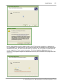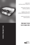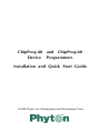
1
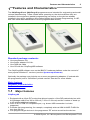
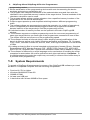
ChipProg-48 and ChipProg-40
Device Programmers
Installation and Quick Start Guide
© 2008 Phyton, Inc. Microsystems and Development Tools
ChipProg-48 and ChipProg-40 Device
Programmers
© 2008 Phyton, Inc. Microsystems and Development Tools
All rights reserved. No parts of this work may be reproduced in any form or by any
means - graphic, electronic, or mechanical, including photocopying, recording, taping,
or information storage and retrieval systems - without the written permission of the
publisher.
Products that are referred to in this document may be either trademarks and/or
registered trademarks of the respective owners. The publisher and the author make no
claim to these trademarks.
While every precaution has been taken in the preparation of this document, the
publisher and the author assume no responsibility for errors or omissions, or for
damages resulting from the use of information contained in this document or from the
use of programs and source code that may accompany it. In no event shall the
publisher and the author be liable for any loss of profit or any other commercial
damage caused or alleged to have been caused directly or indirectly by this document.
Printed: December 2008 in (whereever you are located)
ChipProg-48 and ChipProg-40 Device Programmers
3
Table of Contents
Part I Features and Characteristics
5
1
Major features
2
Hardware characteristics
................................................................. 6
3
Software features ................................................................. 7
4
System Requirements
................................................................. 8
................................................................. 5
9
Part II Installation
1
Installing the ChipProgUSB
Software
.................................................................
9
2
Installing the USB .................................................................
Drivers
13
3
Installing the ChipProg
Hardware
.................................................................
16
4
Troubleshooting ................................................................. 18
Part III Programming Operations
20
1
How to check if a device
is blank
.................................................................
20
2
How to erase a device
................................................................. 20
3
How to program a .................................................................
device
20
How to load a file into a buffer................................................................
................................................................
How to edit information before
programming
How to configure the chosen ................................................................
device
How to write information into................................................................
the device
21
21
21
21
4
How to read a device
................................................................. 22
5
How to verify programming
................................................................. 22
6
How to save data on
a disc
.................................................................
22
7
How to duplicate a.................................................................
device
23
Part IV Getting Assistance
23
1
On-line Help
2
Technical Support................................................................. 23
3
Contact Information
................................................................. 24
................................................................. 23
© 2008 Phyton, Inc. Microsystems and Development Tools
4
ChipProg-48 and ChipProg-40 Device Programmers
Index
.................................................................25
© 2008 Phyton, Inc. Microsystems and Development Tools
Features and Characteristics
5
1 Features and Characteristics
The ChipProg-48 and ChipProg-40 programmers are intended for engineering and small
volume manufacturing. These models allow operating on the devices before they are
installed in the equipment (parallel programming) as well as on the devices already
installed in the user's equipment (the method known as In-System Programming, or ISP,
that uses serial data transmission into the programmable device).
Standard package contents:
·
·
·
·
One programmer unit
One power adapter 12V/1A+
One USB link cable
One CD with the ChipProgUSB software
The ChipProgUSB software runs on the IBM PC hardware platform under the control of
most popular Windows™ versions (see the System requirements).
Optionally the package may include one or more programming adapters (if ordered with
the programmer) and a “QuickStart” printed manual. See also for more details:
Major features
Hardware characteristics
Software features
1.1 Major features
ChipProg-48
1. Equipped with a 48 pin ZIF socket that allows insersion of the DIP-packed devices with
the package width from 300 to 600 mil (7.62 to 15.24 mm) and the number of leads up
to 48 without additional adapters.
2. Links to a PC USB 2.0 compatible port, e.g. slower USB connection is al also
supported.
3. Provides fast programming; for example, completely writes a 64M bit NOR FLASH for
less than 50 sec.
4. Can program target devices in the programmer ZIF socket as well as the devices
© 2008 Phyton, Inc. Microsystems and Development Tools
6
ChipProg-48 and ChipProg-40 Device Programmers
installed in the equipment (ISP mode).
5. An unlimited number of ChipProg-48 tools can be driven from multiple USB ports of one
computer (or via a USB hub) to provide concurrent programming of multiple devices of
the same type.
6. Has a button for fast manual launch of any single operation or a butch of operations.
7. Has three LEDs for displaying the programming status (“Good”, “Busy”, “Error”).
ChipProg-40
1. Equipped with a 40 pin ZIF socket that allows insersion of any DIP-packed devices with
the package width from 300 to 600 mil (7.62 to 15.24 mm) and the number of leads up
to 40 without additional adapters.
2. Links to a PC USB 2.0 compatible port, e.g. slower USB connection is al also
supported.
3. Provides fast programming; for example, completely writes a 64M bit NOR FLASH for
less than 50 sec.
4. Can program target devices in the programmer ZIF socket as well as the devices
installed in the equipment (ISP mode).
5. An unlimited number of ChipProg-40 tools can be driven from multiple USB ports of one
computer (or via a USB hub) to provide concurrent programming of multiple devices of
the same type.
6. Has a button for fast manual launch of any single operation or a butch of operations.
7. Has three LEDs for displaying the programming status (“Good”, “Busy”, “Error”).
ChipProg-48 and ChipProg-40 - what
is the difference?
1. ChipProg-48 has a 48-pin ZIF socket while ChipProg-40 has a 40-pin ZIF socket.
2. ChipProg-48 support more devices than ChipProg-40 and in particular ChipProg-40
does not support any programmable logical devices (PLDs).
3. ChipProg-48 has no limitation in terms of the future device support while ChipProg-40
has some hardware limitations.
1.2 Hardware characteristics
ChipProg-48
1. The programmer has a 48-pin ZIF socket with a lever that enables to insert
and clamp any DIP-packed devices with the package width from 300 to 600 mil (7.62
to 15.24 mm) and with the number of leads up to 48.
2. Adapters for programming devices in the SDIP, PLCC, SOIC, SOP, PSOP, TSOP,
TSOPII, TSSOP, QFP, TQFP, VQFP, QFN, SON, BGA, CSP and other packages are
available from Phyton and many third parties.
3. The programmer is built on the base of a very fast and productive 32-bit embedded
microcontroller and FPGA. These resources allow adding new targets to the device list
by quite a simple software update.
4. Most timing-critical parts of the programming algorithms are implemented on the FPGA
devices and do not involve any operations on the embedded microcontroller that would
slow down the programming speed.
5. Implemented in the FPGA devices logical drivers enable outputting logical signals of
any level (low, high, Pullup, Pulldown and external clock generator) to any pin of the
programming ZIF socket.
6. The tool hardware is featured by a few 10-bit digital-to-analog converters for accurate
settings of the analog signals.
7. The tool hardware enables accurate programming of the rising and falling edges of the
generated analog signals.
8. The tool hardware automatically adjusts the generated analog signals.
9. The generated analog signals for both the target supplying and programming can be
outputted to any pins of the device being programmed.
© 2008 Phyton, Inc. Microsystems and Development Tools
Features and Characteristics
7
10.The tool hardware can connect any pin of the device being programmed to the
“Ground” level.
11.The tool hardware checks if every pin of the target device is reliably fixed by a ZIF
socket’s contacts (“bad contact” checking).
12.The tool hardware protects itself and the target device against incorrect insertions and
other issues causing a sharp increase the currents though the target device circuits.
This “over current” protection is very fast and reliable.
13.The target device pins are protected against the electrostatic discharge.
14.The tool’s hardware has a programmable clock generator.
15.The self-testing procedure automatically executes at any time the programmer is
powered on.
ChipProg-40
1. The programmer has a 40-pin ZIF socket with a lever that enables to insert
and clamp of any DIP-packed devices with the package width from 300 to 600 mil
(7.62 to 15.24 mm) and with the number of leads up to 40.
2. Adapters for programming devices in the SDIP, PLCC, SOIC, SOP, PSOP, TSOP,
TSOPII, TSSOP, QFP, TQFP, VQFP, QFN, SON, BGA, CSP and other packages are
available from Phyton and many third parties.
3. The programmer is built on the base of a very fast and productive 32-bit embedded
microcontroller and FPGA. These resources allow adding new targets to the device list
by quite a simple software update.
4. Most timing-critical parts of the programming algorithms are implemented on the FPGA
devices and do not involve any operations on the embedded microcontroller that would
slow down the programming speed.
5. Implemented in the FPGA devices logical drivers enable outputting logical signals of
any level (low, high, Pullup, Pulldown and external clock generator) to any pin of the
programming ZIF socket.
6. The tool hardware is featured by a few 10-bit digital-to-analog converters for accurate
settings of the analog signals.
7. The tool hardware enables accurate programming of the rising and falling edges of the
generated analog signals.
8. The tool hardware automatically adjusts the generated analog signals.
9. The generated analog signals for both the target supplying and programming can be
outputted to any pins of the device being programmed.
10.The tool hardware can connect any pin of the device being programmed to the
“Ground” level.
11.The tool hardware checks if every pin of the target device is reliably fixed by a ZIF
socket’s contacts (“bad contact” checking).
12.The tool hardware protects itself and the target device against incorrect insertions and
other issues causing a sharp increase the currents though the target device circuits.
This “over current” protection is very fast and reliable.
13.The target device pins are protected against the electrostatic discharge.
14.The tool’s hardware has a programmable clock generator.
15.The self-testing procedure automatically executes at any time the programmer is
powered on.
1.3 Software features
1. Works under control of Windows 95/98/ME/2000/XP/Vista.
2. Friendly, intuitive graphic user interface.
3. Includes a set of basic commands: Blank Check, Erase, Read, Write, Verify, Lock, Set
Configuration Bits, Data Memory Support, etc., executed by a single mouse click or via
menu.
4. Enables programming a batch of the commands above executed one after one by a
manual start or by a mouse click or automatically upon the device insertion into the
© 2008 Phyton, Inc. Microsystems and Development Tools
8
ChipProg-48 and ChipProg-40 Device Programmers
programming socket.
5. Allows serialization of the programming devices with auto incrementing the device
numbers and storing a serialization log.
6. The program can calculate checksums of the selected data array and then write the
checksum into a specified memory location of the target device. Several methods of the
checksum calculation can be used.
7. The program allows writing a unique signature into a specified memory location of the
target device for the device identification.
8. Project support speeds up and simplifies switching between different programming
tasks.
9. The software allows pre-programming a particular operation (or a chain of operations),
which is supposed to be automatically triggered when the programmer hardware
detects insertion of the target device into the programming socket.
10.Unlimited number of memory buffers can be opened in the main ChipProgUSB
window.
11.The software supports a multiple programming mode for concurrent programming of
same type target devices on same type of the programmers connected to one cluster.
The cluster size has no influence on the programming speed.
12.The software includes a full-scale binary editor allowing manual modification of the
data in buffers as well as such helpful functions as Search and Replace, Fill, Compare,
Copy, Invert, Calculate Checksum, and OR, AND, XOR logical operations on the blocks
of data.
13.Loading and saving files in several standard and proprietary formats: Binary, Standard
Extended Intel HEX, Motorla S-record, POF, JEDEC, PRG, Holtek OTP, ASCII HEC,
ASCII OCTAL, Angstrem SAV. Special non-standard formats can be added on request.
14.The software is featured by a script language and a mechanism of handling the script
scenarios for automation the routine operations and chips replications. Limitation: In
the Multiprogramming mode the scripts may not modify a content of the buffer dump in
a process of the programming.
1.4 System Requirements
To control a ChipProg-48 programmer by means of the ChipProgUSB software you need
an IBM PC-compatible computer with the following components:
·
·
·
·
·
Pentium-III CPU or higher
Windows 98/2000/XP/Vista OS
256MB of RAM
At least one USB port
A hard drive with at least 200MB of free space
© 2008 Phyton, Inc. Microsystems and Development Tools
Features and Characteristics
9
2 Installation
2.1 Installing the ChipProgUSB Software
Insert the distributive ChipProgUSB disc into a CD drive of your PC. In a few seconds the
picture below will appear on the screen.
click the install button and then follow the series of prompts that will lead you through the
installation process. If your computer cannot automatically start up the disc open the 'My
Computer' folder on the PC desktop, expand the DVD-RAM or CD-ROM drive and click
the Setup.exe file icon.
Carefully read the license agreement; if you agree with its terms check the I accept... radio
button. Then click the Next button.
© 2008 Phyton, Inc. Microsystems and Development Tools
10
ChipProg-48 and ChipProg-40 Device Programmers
If another, usually older, version of the ChipProgUSB software has been already installed
and configured on your PC you may wish to keep the software configuration working with
the new software version being installed. If so check the Transfer working environment
from version box, select the version number which configuration you want to inherit and
click the Next button.
If another, usually older, version of the ChipProgUSB software has been already installed
on your PC you may wish to uninstall this version from your computer before installing a
new version. If so check appropriate boxes with previously installed versions of the
ChipProgUSB software and click the Next button. The chosen version will be removed
from your PC.
© 2008 Phyton, Inc. Microsystems and Development Tools
Installation
11
By default the program offers to install the ChipProgUSB program into the destination
folder ending with the abbreviation of the software version number. You can change it as
you wish. Then click the Next button to begin the product installation. Then you can watch
the process of the software installation.
At the end the installer will create a folder with ChipProgUSB tools' and documents'
shortcuts:
© 2008 Phyton, Inc. Microsystems and Development Tools
12
ChipProg-48 and ChipProg-40 Device Programmers
Phyton ChipProgUSB - invokes the ChipProgUSB executable file and starts
operations for the ChipProg-48 and ChipProg-40 programmers working in a single
programming mode, e.g. when the programmer works alone.
< This shortcut starts the ChipProgUSB
program to control a single programmer. Do
not use this shortcut for starting a cluster of
single ChipProg programmers connected to one
computer for concurrent programming of
multiple devices!
Phyton ChipProgUSB -- Gang Mode - invokes the ChipProgUSB executable file and
starts operations on multiple ChipProg-48 and ChipProg-40 programmers connected to
one computer for concurrent device programming by multiple programmers.
< This shortcut starts the ChipProgUSB program
to control a cluster of single ChipProg
programmers connected to one computer for
concurrent programming of multiple devices (
Gang mode).
Phyton ChipProgUSB Demo - invokes a demo version of the ChipProgUSB software that
allows evaluating the product without its hardware.
ChipProgUSB On-Line Help - opens the programmer on-line Help document.
© 2008 Phyton, Inc. Microsystems and Development Tools
Installation
13
ChipProgUSB User's Guide - opens the programmer user's guide in the PDF format.
Phyton WEB site - opens an Internet browser with the www.phyton.com website.
Programming Adapters - opens the adapters.chm file that list all the Phyton
programming adapters with their short descriptions and wiring diagrams.
Revision History - opens the ChipProgUSB versions history file.
Uninstall Phyton ChipProgUSB Programmer - starts a process of removing the
ChipProgUSB program from your computer.
2.2 Installing the USB Drivers
If you have the Windows 2000/XP/Vista operating systems on your computer the USB
drivers will be automatically installed on your PC in a process of the software installation.
If you have the Windows 98/ME operating systems then after completing the software
installation you should install the USB drivers to control the tools from a computer.
To initiate the USB drivers installation procedure connect a ChipProg unit to the USB port
of your computer via the cable enclosed to the programmer's kit. You should see the
following pop-up warning on computer desktop. The FTDI FT8U2XX is the device used in
the ChipProg-48 and ChipProg-40 hardware for communicating to a PC via a USB port.
then the Found New Hardware Wizard dialog will appear:
© 2008 Phyton, Inc. Microsystems and Development Tools
14
ChipProg-48 and ChipProg-40 Device Programmers
Select the 'Install from a list or specific location' option and click the Next button. The
following dialog prompts to specify the drivers location.
The USB drivers are located in the Drivers.USB folder on the distributive disc supplied
with the programmer - you should type in a full path to this folder or browse the CD
ROM drive.
If you installed the ChipProgUSB software not from a Phyton distributive disc but
downloaded from the Phyton website you should also download the USB drivers located
on the http://www.phyton.com/htdocs/support/drivers.shtml webpage. Then you
should specify a path to the downloaded drivers in the dialog above.
After you clicked the Next button the wizard program starts searching for the FTDI
device driver and in a few seconds you will get the warning below:
© 2008 Phyton, Inc. Microsystems and Development Tools
Installation
15
Phyton guarantees that the USB drivers for the FTDI device supplied on a distributive
CD or available for download from the Phyton website are compatible with the Microsoft
Windows 98, 2000, XP and Vista OSs and use of them will not impair or destabilize the
correct operation of your computer system. Click the Continue Anyway button to
continue. The program begins to load the drivers and you can watch the progress of the
download.
© 2008 Phyton, Inc. Microsystems and Development Tools
16
ChipProg-48 and ChipProg-40 Device Programmers
Upon completing the installation process you will get the final wizard prompt below.
Click the Finish button to complete the installation process. Then message on the
computer desktop will pop up:
Now you can use the ChipProg connected to your computer.
2.3 Installing the ChipProg Hardware
It is a mandatory you would use the original power adapter 12V/1A received with the
ChipProg programmer. Any substitutions should be agreed with Phyton. It is also highly
recommended to use the USB link cables received with the programmers.
For the programmer to be used in a single-programming mode:
© 2008 Phyton, Inc. Microsystems and Development Tools
Installation
17
Powering the
programmer
Plug the power adapter to the ~110/240V outlet. Connect an
output plug of the power adapter to the coaxial connector on
the rear panel of the programmer and make sure that the
"Good" green LED on the programmer is on.
Connecting to a
PC
Connect a USB port of your PC to a USB connector on the rear
panel of the programmer by means of the USB cable. It's highly
recommended to connect the programmer to a USB slot on the
computer main unit and do not connect it through a USB hub,
especially through a passive hub.
Starting up
Start the Phyton ChipProgUSB program. The easiest way is
to click the shortcut at the left copied on the desktop. If the
programmer passes the startup test succesfully the first dialog
promts you to choose a particular programmer model to work
with. Select the ChipProg-48 or ChipProg-40. Remember that
chosing a wrong programmer model will cause the tool
mulfunctioning. The ChipProgUSB main window will open and
you will be able to work with the tool.
For the programmers to be used in a multi-programming mode, e.g. connected to
one computer:
Powering the
programmers
Plug power adapters of each programmer to be connected in
one programming cluster to the 110/240V outlets. Connect
output plugs of the power adapter to the coaxial connectors on
the rear panels of all the programmer and make sure that the
"Good" green LEDs on each of them are on.
Connecting the
programmers to
a cluster
Connect USB ports of your PCs to USB connectors on the rear
panels of the programmers by means of the USB cables. It's
highly recommended to connect the programmers to USB slots
on the computer main unit and do not connect them through a
USB hub, especially through a passive hub.
Starting up
Start the Phyton ChipProgUSB - Gang Mode program. The
easiest way is to click the shortcut at the left copied on the
desktop. If all the programmers connected in one cluster pass
the startup test succesfully the first dialog promts you to assign
the number from one to N to each programmer included in the
cluster. To assign the number push a Start button on a top
panel of each programmer one by one. Then the
ChipProgUSB main window will open and you will be able to
work with the tool.
© 2008 Phyton, Inc. Microsystems and Development Tools
18
ChipProg-48 and ChipProg-40 Device Programmers
2.4 Troubleshooting
Potential problems with the ChipProgUSB software installation
If you meet a problem installing the ChipProgUSB software from a distributive disc make
sure the disc surface has no scratches and other defects. Is the disc is defective you may
require the disc replacement from Phyton or a local distributor. However, the easiest way
to get the latest software version go to the download webpage on the Phyton website
(URL: http://www.phyton.com/htdocs/support/update.shtml ), select the ChipProgUSB.
exe file, double click on the file name to begin the file download. Save the ChipProgUSB.
exe file on a hard drive of your computer.
Then you should download the ChipProg USB drivers. Go to the webpage http://www.
phyton.com/htdocs/support/drivers.shtml and double click the Download the USB drivers
link to download the drivers. Save the USB_drivers.exe file on a hard drive of your
computer.
Both the ChipProgUSB.exe and USB_drivers.exe files are self-extracted archives.
Invoke the ChipProgUSB.exe file to extract the archive and to install the ChipProgUSB
software on your computer. Then invoke the USB_drivers.exe file to extract the archive;
then store the extracted drivers on a hard drive of your computer. You will need these
drivers to istall them on your computer later.
Potential problems with installing the USB drivers for ChipProg
If your computer does not detect a ChipProg programmer when you connect it via a USB
cable and you cannot drive the programmer from the ChipProgUSB program it is possible
that there is already installed USB driver for another FTDI device similar to those one
installed in your ChipProg programmer. In some cases this may cause a conflict between
two drivers. It is also possible that the FTDI USB driver has been incorrectly installed on
your computer. In both cases it is recommended to uninstall the USB device that conflicts
with the ChipProg FTDI device. Right click on the My Computer icon on the computer
desktop to open the System Properties dialog, open the Hardware tab and click the
Device Manager button. In the opened device tree expand the Universal Serial Bus
controllers group select the FTDI FT8U2XX Device, right click on it and in the pull-down
menu click the Uninstall line. Then repeat an attempt to install the USB drivers following
the instructions of the Installing the USB drivers topic.
Potential problems with installing the ChipProg hardware
If you could manage to successfully install the ChipProgUSB software and ChipProg
USB drivers you should not meet any problems driving your ChipProg programmer. If,
however, you get the error message below:
© 2008 Phyton, Inc. Microsystems and Development Tools
Installation
19
check if the power adapter is plugged into the ~110/240V outlet, its output plug is
connected to the ChipProg unit and the green LED "Good" is on, e.g. the programmer is
powered. If it is powered but the error persists check if the USB cable is not broken and
reliably plugged on both ends. If the cable has worn out or if it has open wires replace the
cable by a USB A-B type double-shielded (with a dual foil and braid) cable. Use of not
shielded cables may case unstable work of the ChipProg programmer and the electromagnetic emission exceeding the norms of the US and European standards.
© 2008 Phyton, Inc. Microsystems and Development Tools
20
ChipProg-48 and ChipProg-40 Device Programmers
3 Programming Operations
Sub-topics of this chapter describe all the basic ChipProg-40 and ChipProg-48 operations
in a single programming mode, when a device is programming in the programmer socket.
Specific operations for programming more than one device at one time are described in
the full ChipProg User's Guide.
The ChipProg-48 and ChipProg-40 programming operations are described in details in
the ChipProg PDF manual that can be found on the Phyton distributive disc or
downloaded from the http://www.phyton.com/htdocs/support/update.shtml web page.
3.1 How to check if a device is blank
1.
Select the target device type, pressed the button Select Device in the Main toolbar
or select the command Main menu > Configure > Select device.
2.
Insert a device of the selected type into the programmer socket or into the adapter
socket.
3.
a) Click the Check button on the main toolbar or
b) Double click on the Blank check function line in the Function list of the
Program Manager window or
c) Select the Blank check function line in the Function list of the Program
Manager window and click the Execute button or
d) Select the Main menu > Commands and click on the Blank check line
then wait for the message Checking … OK in the Program Manager window, or
for the warning message if the device is not blank
3.2 How to erase a device
1.
2.
Make sure the device is electrically erasable. Some devices are not erasable;
these may be programmable once, UV erasable, or over-writable – in this case
the Erase button is blocked (grey out).
If the device is electrically erasable:
a) Click the Erase button on the main toolbar or
b) Double click on the Erase function line in the Function list of the Program
Manager window or
c) Select the Erase function line in the Function list of the Program Manager
window and click the Execute button or
d) Select the Main menu > Commands and click on the Erase line
then wait for the message Erasing … OK in the Program Manager window or for
the warning message if the device is not blank after erasing.
3.3 How to program a device
In order to program a blank device you need to perform a few consecutive operations:
·
·
·
·
load the file, that you want to write to the device;
edit the file (if necessary);
configure the device to be programmed (if necessary);
write the prepared information into the device and verify the programming.
© 2008 Phyton, Inc. Microsystems and Development Tools
Programming Operations
21
3.3.1 How to load a file into a buffer
1.
Select the Main menu > File > Load or click the Load button on the local toolbar of
the Buffer window.
2.
In the pop-up dialog box enter the source file name, select the file format,
addresses, buffer and sub-level to load the file to.
3.
Wait for the message File loaded: "......" in the Program Manager window or for a
warning message if the file cannot be loaded for some reason.
3.3.2 How to edit information before programming
1.
If you need to modify source data before writing into the target device, then open
the Buffer Damp window. Never forget that the View button should be released to
enable editing.
2.
Make necessary changes in the window via the Modify dialog or appoint the data to
be modified and type the new data over the old data.
3.3.3 How to configure the chosen device
1.
If any parameters displayed in the Device and Algorithm Parameters window can be
changed by editing, their names are shown in blue.
2.
Click on the name of the parameters to be changed to open an appropriate dialog. Set
a new value for the parameter or check/uncheck appropriate boxes and click OK. The
parameter value will change its color to red.
3.
Continue for other parameters that should be changed. All preset changes will
become effective in the target device only upon programming via the Program
Manager programming function.
3.3.4 How to write information into the device
1.
Click the Options tab in the Program Manager window. Check the options you
need. We recommend that you always check the Blank check before programming
and the Verify after programming check-boxes to make programming more reliable.
2.
Click the Program Manager tab. Select the Program line in the Function box,
and double click it to start programming of the primary memory layer (Code) or
click the Execute button to do so. Alternatively, you can do the same by clicking the
big Program button or selecting the command Menu > Commands > Program.
3.
Wait for the message Programming … OK in the Operation Progress box of the
Program Manager tab. If an error has occurred the ChipProgUSB issues an error
message.
4.
Execution of the main Program function (always shown in the beginning of the
Function list) writes a specified buffer layer content to the Code device memory.
However, other buffer layers may exist for the selected device (Data, User, etc.). If
more than one buffer layer exists for the selected device go down to the list of
functions, expand those that are collapsed and execute the Program functions for
as many types of memory as the device has (Data, User, etc.). Skip this if just one
memory layer Code exists for the device.
© 2008 Phyton, Inc. Microsystems and Development Tools
22
ChipProg-48 and ChipProg-40 Device Programmers
5.
IMPORTANT! After programming of all the memory layers (Code, Data, User, etc.)
you need to program the options preset in the Device and Algorithm Parameters
window, if they have been modified. Go down to the Device parameters & ID line,
expand it if collapsed, select the Program function and double click it. Continue
until every parameter that was changed in the Device and Algorithm Parameters
window is successfully programmed.
6.
Some microcontrollers can be protected against unauthorized reading of the written
code by setting a set of Lock bits. Go down to the Lock bits line, expand it if
collapsed and double click the lock bit# lines one by one. You can optionally lock
only certain parts of the device memory. Continue until every lock bit is set.
7.
After every operation above make sure that you watch the Ok [xxxxx... Ok]
message in the Operation Progress box of the Program Manager tab. In case
you get an error message stop the programming and troubleshoot the issue.
3.4 How to read a device
There are several ways for reading the device content to an active buffer:
a) Click the Read button on the main toolbar or
b) Double click on the Read function line in the Function list of the Program
Manager window or
c) Select the Read function line in the Function list of the Program Manager
window and click the Execute button or
d) Select the Main menu > Commands and click on the Read line
then wait for the message Reading … OK in the Program Manager window or for the
warning message if the device could not be read out.
3.5 How to verify programming
There are several ways for checking if the device was programmed correctly:
a) Click the Verify button on the main toolbar or
b) Double click on the Verify function line in the Function list of the Program
Manager window or
c) Select the Verify function line in the Function list of the Program Manager
window and click the Execute button or
d) Select the Main menu > Commands and click on the Verify line
then wait after that which wait for the message Verifying … OK in the Program
Manager window or for the warning message if the device failed during the
verification process.
3.6 How to save data on a disc
1.
After you have read out the device content into the Buffer or a specified Buffer
layer you may need to save the read data on a PC disc. To save the
data:
a) Click the Save button on the local toolbar of the Buffer window or
b) Select the Main menu > File > Save
© 2008 Phyton, Inc. Microsystems and Development Tools
Programming Operations
2.
23
In the pop-up dialog specify the destination file name, format, start and end
addresses of the source (the buffer), and the source sub-level, and click OK.
3.7 How to duplicate a device
1.
2.
3.
4.
5.
Insert the master device to be copied (duplicated) into the programmer
socket.
Read it to an active buffer
Wait for the message Reading… OK in the Operation Progress box of the
Program Manager tab in the Program Manager window. Make sure the
master device content is in a current buffer.
Remove the master device from the socket and replace it with a blank device
to be programmed. If necessary, check to see if it is blank.
Program the device. If you need to make more than one copy of the master
device repeat the operations #4 and #5 as may times as necessary.
4 Getting Assistance
4.1 On-line Help
The ChipProgUSB software has a pretty comprehensive context-sensitive on-line
Help. To access it press the F1 key or use the Help menu. Almost every
ChipProgUSB dialog, message box and menu has its own context-sensitive help,
which can be invoked for the active dialog or menu by pressing F1.
In most cases you can find the necessary topic by searching for a keyword. For
example, if you type "Verify" in the first box of the Find tab, the third box will list the
topics related to the programming verification. Choose an appropriate topic from this
list and press Display.
4.2 Technical Support
During a product’s warranty period Phyton provides technical support free of charge.
Though we have been selling the ChipProg programmers for many years the product
software may contain minor bugs and some programming algorithms may not work
stable on some of thousand supported devices. We kindly ask you to report bugs
when you get an error message or have a problem with programming a particular
device or devices. We commit prompt checking your information and fixing the
detected bugs.
To minimize difficulties operating with ChipProgUSB it is highly recommended to get
familiar with the manual before using the programmer. The ChipProgUSB user
interface is quite standard and intuitive, however it includes some specific functions
and control that the user should learn about.
Before contacting Phyton
·
·
Make sure that you use the latest ChipProgUSB version always available for free
download from the http://www.phyton.com.
Make sure the detected error can be reproduced in the same working environment
and is not a casual glitch.
When contacting us
© 2008 Phyton, Inc. Microsystems and Development Tools
24
ChipProg-48 and ChipProg-40 Device Programmers
Please, provide our technical support specialists with the following information:
·
·
·
·
·
·
·
Your name, the name of your company, your contact telephone number and your
e-mail address.
Name of the ChipProg model and its serial number, if exists.
Date of purchase, the Phyton invoice number, if available.
Software version number taken from the About information box of the Help menu..
Basic parameters of your computer and operating system.
The device type, mechanical package and the type of the adapter if it's used
Descriptions of detected errors, relevant bug reports and error screen shots.
Please send your requests or questions to [email protected]. This is the easiest
way to get professional and prompt help. Also, see Contact Information.
4.3 Contact Information
Phyton Inc., Microsystems and Development Tools
7206 Bay Parkway, 2nd floor
Brooklyn, New York 11204
USA
Web address: www.phyton.com
E-mail contacts:
General inquiry: [email protected]
Sales: [email protected]
Technical Support: [email protected]
Tel: 1-718-259-3191
Fax: 1-718-259-1539
© 2008 Phyton, Inc. Microsystems and Development Tools
25
Index
Contact Information
24
-D-C-
Drivers
USB 13
Duplicate a device
23
Check Blank 20
ChipProg-48 5
Auto Programming 6, 7
automatic insertion check 6
Bit lock 7
Edit Information to be programmed 21
Blank Check 7
Erase 20
block operations 7
brief characteristics 5
buffer 7
Button "START" 5
Hardware Installation
checksum 7
Gang mode 16
Configuration Bits 7
Installation 16
editor 7
Multiprogramming mode 16
Erase 7
Power adapter 16
hardware characteristics 6
USB cable 16
LED "Busy" 5
Help
LED "Error" 5
On-line 23
LED "Good" 5
How to Get On-line Help 23
Lock 7
major features 5
multi programming 6
multiple buffers 7
Read 7
Install ChipProg 9
script language 7
Install the ChipProg Software
scripts 7
Starting the Gang programming mode
serialization 7
Starting the Single programming mode
signatures 7
Installing the USB Drivers 13
software characteristics 7
start-up test 6
Verify 7
Write 7
Load the file into the buffer 21
ZIF socket 5
Configure the device to be programmed 21
-E-
-H-
-I-
-L-
© 2008 Phyton, Inc. Microsystems and Development Tools
26
ChipProg-48 and ChipProg-40 Device Programmers
-OOn-line Help
-T23
-P-
Technical Support 23
Troubleshooting
CD 18
Power adapter 18
USB cable 18
USB drivers 18
Program a Device 20
Programmer ChipProg-48 5
Programming
check blank 20
configure the device 21
duplicate a device 23
USB Drivers 13
edit Information 21
erase 20
file format 21
load the file 21
Verify programming 22
program a Device 20
program functions 20
read a device 22
save the data 22
Write Information into the Device
verify 22
write Information into the Device 21
-U-
-V-
-W-
-RRead a Device
22
-SSave the data read out from a device
Support 23
System Requirements
Windows 8
Windows OS 8
22
© 2008 Phyton, Inc. Microsystems and Development Tools
21