1
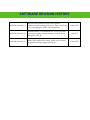
VEMCO, a Division of AMIRIX Systems Inc. DOC-5072-07 25 Jul 2012 AMIRIX Systems Inc. Warranty and Disclaimer WARRANTY AMIRIX Systems Inc.’s warranty period for the Product is one (1) year from date of product shipment. AMIRIX Systems Inc. (AMIRIX) warrants that on the date of shipment all Products manufactured by AMIRIX are free from defects in material and workmanship under normal use and service. This warranty applies to the components necessary for equipment upgrades, i.e. the VR1/VR2 to VR2 upgrade. This warranty does not apply to any equipment, materials or design supplied by Buyer or to re-battery services provided by AMIRIX. This warranty shall survive delivery only on the conditions and subject to the limitations set forth below. NOTICE PERIODS To receive a warranty remedy for a Product, Buyer must contact AMIRIX’s Customer Support Department during the warranty period to receive the Return Material Authorization (“RMA”) instructions. Each defective Product returned for warranty remedy must be shipped at the Buyer’s expense according to the RMA instructions and must include reasonable proof that the claimed defect is due to a matter embraced within the warranty set forth above and that such defect did not result from any act or omission of Buyer, including but not limited to any failure to operate and maintain the Product in accordance with AMIRIX’s applicable written instructions. REMEDY AMIRIX’s liability, and the Buyer’s exclusive remedy under this warranty, as to a defect in material or workmanship, is limited to the repair of such defect in the accessory, equipment or part in which the defect appears or, at AMIRIX’s option, to the replacement of such accessory, equipment or part with a similar item free from defect. As to any item repaired by AMIRIX or furnished as a replacement by AMIRIX, AMIRIX’s liability and the Buyer’s exclusive remedy to the repair or replacement of such item for any further defect in material or workmanship, provided AMIRIX receives written notice at Halifax, Nova Scotia, of such further defect from BUYER within ninety (90) days after the repaired or replaced item is shipped to BUYER and provided that BUYER returns same to AMIRIX as provided under “Notice Periods”. RETURNED ITEMS All repairs, replacements and corrections described above shall be performed by AMIRIX at its plant at Halifax, Nova Scotia, or at such other place as may be mutually agreeable, and with reasonable care and dispatch in order that the Product, accessory, equipment or part will not be kept out of service longer than necessary. Return to BUYER of a repaired, replacement, or corrected accessory, equipment, part or Product shall be at AMIRIX’s expense. Title to and risk of loss of the Product, accessory, equipment, or part returned to AMIRIX pursuant hereto shall at all times remain with the BUYER, except that title to a returned accessory, equipment, part, or Product shall pass to AMIRIX concurrently with shipment to BUYER of any item furnished by AMIRIX to BUYER as a replacement therefore. AMIRIX shall have only such responsibility for any Product, accessory, equipment, or part owned by the BUYER and in the possession of AMIRIX as is chargeable by law to a bailee for hire, but shall not be chargeable for loss of use thereof. WEAR AND TEAR Normal wear and tear and the need for regular maintenance shall not constitute a defect under this warranty. DISCLAIMER AND RELEASE THE WARRANTIES, OBLIGATIONS AND LIABILITIES OF AMIRIX AND THE REMEDIES OF BUYER SET FORTH HEREIN ARE EXCLUSIVE AND IN SUBSTITUTION FOR, AND BUYER HEREBY WAIVES AND RENOUNCES, ALL OTHER WARRANTIES AND OBLIGATIONS OF AMIRIX AND ANY ASSIGNEE OF AMIRIX AND ALL RIGHTS, CLAIMS AND REMEDIES OF BUYER AGAINST AMIRIX, EXPRESS OR IMPLIED, ARISING BY LAW OR OTHERWISE, WITH RESPECT TO ANY NONPERFORMANCE OR DEFECT IN THE PRODUCT OR IN ANY OTHER THING DELIVERED UNDER THIS AGREEMENT, INCLUDING BUT NOT LIMITED TO: (A) ANY IMPLIED WARRANTY OF MERCHANTABILITY OR FITNESS FOR A PARTICULAR PURPOSE; (B) ANY IMPLIED WARRANTY ARISING OUT OF COURSE OF PERFORMANCE, COURSE OF DEALING OR USAGE OF TRADE; (C) ANY OBLIGATION, LIABILITY, CLAIM OR REMEDY IN TORT, WHETHER OR NOT ARISING FROM THE NEGLIGENCE OF AMIRIX OR ANY ASSIGNEE OF AMIRIX, ACTUAL OR IMPUTED; (D) ANY OBLIGATION, LIABILITY, RIGHT, CLAIM, OR REMEDY FOR LOSS OF OR DAMAGE TO THE PRODUCT, FOR LOSS OF USE, REVENUE, OR PROFIT WITH RESPECT TO THE PRODUCT; OR FOR ANY OTHER DIRECT, INCIDENTAL OR CONSEQUENTIAL DAMAGES; AND (E) AMIRIX MAKES NO REPRESENTATION THAT THE PRODUCT WILL NOT INFRINGE ANY PATENT OR OTHER RIGHTS OF ANY PERSON AND BUYER AGREES TO INDEMNIFY AMIRIX AND HOLD AMIRIX HARMLESS FROM ANY AND ALL CLAIMS AND LIABILITIES WITH RESPECT TO SAME TOGETHER WITH ANY CLAIMS AND LIABILITIES WITH RESPECT TO ANY INFRINGEMENT OF ANY PATENT OR OTHER RIGHTS OF ANY PERSON ARISING AS A RESULT OF BUYER'S PRODUCTS, TECHNOLOGY, ACTIVITIES, OR OTHERWISE. LICENSE AGREEMENT AMIRIX grants to the Buyer a limited, personal license, with no right to sub-license, to use the Intellectual Property (“IP”) and Embedded Software in the manner set out in the Documentation. The Embedded Software and IP are not sold to Buyer. All property rights, including Intellectual Property Rights, remain with AMIRIX. All rights related to the Embedded Software not expressly licensed to the Buyer are reserved to Amirix. BUYER shall not permit any person other than BUYER and its employees to use or make use of the Embedded Software and/or IP. BUYER shall not, and shall not permit any third party to, modify, adapt, translate, reverse engineer, decompile, disassemble, or create derivative works based on the Embedded Software and/or IP. This license is assigned to the Product with which you have acquired the Embedded Software and/or IP. If the Product purchased is a Transmitter product, be advised that the license life is equal to the operational life. NEGOTIATED AGREEMENT It is fully understood by the parties that the price of the Product and other mutual agreements of the parties set forth in this agreement were arrived at in consideration of this warranty, SPECIFICALLY INCLUDING THE WAIVER, RELEASE AND RENUNCIATION BY BUYER SET FORTH ABOVE (DISCLAIMER AND RELEASE). © (2012) AMIRIX Systems Inc. All rights reserved. The information contained herein includes information which is confidential and proprietary to AMIRIX Systems Inc. and may not be used or disclosed without prior written consent of AMIRIX Systems Inc. MANUAL Summary This manual is intended to provide our users with the information they require to use the VEMCO Mobile Transceiver (VMT) and the VMT_PC software. VEMCO highly recommends that the user fully read the manual before using the VMT or the software. Section 1 Overview of the VMT and Reader Section 2 Quick Start guide for users who are already familiar with the VMT Section 3 Hardware features of the VMT Section 4 Instructions for using and caring for the VMT Reader Section 5 Overview of the VMT_PC software Section 6 Data Files Section 7 Appendix Questions, comments, or suggestions are welcomed and can be submitted via the web at http://www.vemco.com/contact_form.php. TABLE OF CONTENTS 1 OVERVIEW .................................................................................................................... 1 1.1 Introduction ......................................................................................................................... 1 2 QUICK START GUIDE .................................................................................................. 2 2.1 set up equipment ................................................................................................................. 2 2.2 Set up VMT for deployment ............................................................................................... 2 2.3 Deployment ......................................................................................................................... 3 2.3.1 Considerations when deploying ................................................................................... 3 2.4 Offloading Data .................................................................................................................. 4 3 VMT HARDWARE FEATURES ...................................................................................... 5 3.1 Receiver Cycling................................................................................................................. 6 3.1.1 Receiver On Time......................................................................................................... 6 3.1.2 Duty Cycle .................................................................................................................... 6 3.1.3 Receiver Min and Max on time .................................................................................... 6 3.2 VMT Modes ........................................................................................................................ 7 3.2.1 Sleep Mode ................................................................................................................... 7 3.2.2 Serial Communication Mode ........................................................................................ 7 3.2.3 Normal Operation Mode............................................................................................... 7 3.2.4 Battery Life Monitor..................................................................................................... 7 3.3 Indicator Light .................................................................................................................... 8 3.4 Safety Considerations ......................................................................................................... 9 3.5 Battery Life ....................................................................................................................... 10 3.5.1 Receiver Duty Cycle & Battery Life .......................................................................... 10 3.6 Firmware Updates ............................................................................................................. 11 3.6.1 Instructions ................................................................................................................. 11 3.7 Shipping VMT .................................................................................................................. 11 4 VMT READER .............................................................................................................. 12 4.1 VMT Reader Overview..................................................................................................... 12 4.2 VMT Reader Installation .................................................................................................. 12 4.3 VMT Reader Care ............................................................................................................. 13 5 VMT_PC SOFTWARE .................................................................................................. 14 5.1 VMT_PC software Overview ........................................................................................... 14 5.2 Software Installation ......................................................................................................... 14 5.3 Software Setup .................................................................................................................. 14 5.4 VMT_PC software Menus ................................................................................................ 15 5.4.1 File Menu ................................................................................................................... 15 5.4.1.1 Data directory ................................................................................................ 15 5.4.1.2 Create VUE compatible VRL file ................................................................. 15 5.4.2 Setup Menu................................................................................................................. 15 5.4.2.1 Serial Port ...................................................................................................... 15 5.4.2.2 VMT user settings ......................................................................................... 16 5.4.2.2.1 Examples of common VMT Receiver configurations: ........................... 18 5.4.3 Offload Data Menu ..................................................................................................... 19 5.4.3.1 VUE compatible VRL data file ..................................................................... 20 5.4.3.2 Raw data ........................................................................................................ 20 5.4.4 Study Menu ................................................................................................................ 20 5.4.4.1 Start/Resume Study ....................................................................................... 20 5.4.5 About .......................................................................................................................... 21 5.4.5.1 Application .................................................................................................... 21 5.4.5.2 Reader Info .................................................................................................... 21 6 Data Files .................................................................................................................... 22 6.1 Data File Types ................................................................................................................. 22 6.1.1 VUE compatible VRL data file .................................................................................. 22 6.1.2 Raw RLD files ............................................................................................................ 22 6.2 Data File Header ............................................................................................................... 22 6.3 Data File example ............................................................................................................. 24 7 Appendix ..................................................................................................................... 26 7.1 Physical Specifications ..................................................................................................... 26 7.2 Factory Settings ................................................................................................................ 26 7.3 Cleaning Instructions ........................................................................................................ 27 7.4 Contact Information .......................................................................................................... 27 7.5 Index ................................................................................................................................. 28 SOFTWARE REVISION HISTORY VMT SW Version 2.1.0 Requires VMT firmware version 2.0.2 or greater. Updated to allow Disabling Transmitter, 100% receiver duty cycle, and logging the VMTs own transmissions VMT SW Version 2.2.0 Offloads both the VUE and RAW files. Clock is now only set when new study is started (memory is erased). Name changed to VMT_PC. 7 Jun 2011 VMT SW Version 2.2.2 Added VRL and RLD file exports. Ability to view factory programmed settings. Support for Map-113. 25 July 2012 21 Dec 2010 VEMCO – A Division of AMIRIX Systems 1 OVERVIEW 1.1 INTRODUCTION The VEMCO Mobile Transceiver (VMT) is a hybrid between a 69 kHz coded transmitter and a 69 kHz monitoring receiver (similar to the VR2W-69kHz). It alternates between transmitting acoustic pings and listening for acoustic pings that have been transmitted by VEMCO 69kHz coded transmitters in the area. The time spent in each mode is referred to as the “duty cycle”. For example, if the VMT is in the receiver mode for 20% of the time, it is said to have a receiver duty cycle of 20%. Because the receiver consumes significantly more power than the transmitter, the unit’s battery has a longer life when the receiver has a lower duty cycle. The VMT’s anodized aluminum and polyurethane case is designed for use in water as deep as 1000 metres, making it suitable for deep diving animals. It contains a lithium, factory-replaceable battery (unit must be returned to VEMCO for battery replacement). The VMT contains 8 MB of memory to store approximately one million detections. This data is uploaded to a PC through the VMT Reader unit. The VMT Reader Unit is a high speed optical interface designed specifically for the VEMCO Mobile Transceiver. It has a USB interface for easy connection to modern desktop and laptop PCs, and it is powered by the host computer. VEMCO Mobile Transceiver (VMT) User Manual Page 1 VEMCO – A Division of AMIRIX Systems 2 QUICK START GUIDE 2.1 SET UP EQUIPMENT Use this list the first time the VMT_PC software is being used on a PC. Detailed instructions for each step are given throughout the manual (sections numbers are listed in brackets). Step 1: Connect the VMT reader to the PC (see section 4.2). Step 2: Record the virtual COM port number (see section 4.2). Step 3: Install the VMT_PC software on the PC (see section 5.2). Step 4: Assign a data directory location in the software (see section 5.4.1.1). Step 5: Identify the virtual COM port in the software (see section 5.4.2.1). Step 6: Ensure that your PC is set to precisely to the correct local time before initiating communication with the VMT. 2.2 SET UP VMT FOR DEPLOYMENT Step 1: Place the supplied magnet on the white rectangle on the side of the case and watch the indicator light for flashes. Remove the magnet before the tenth flash. If the magnet is attached to the VMT, remove the magnet for approximately 20 seconds before placing the magnet back on the white mark. Step 2: Insert the VMT into the VMT Reader so the notch in the VMT case lines up with the tab in the reader. Step 3: Open the VMT User Settings window (Setup menu) in the VMT_PC software (see section 5.4.2.2). Step 4: Enter a Study ID (see section 5.4.2.2). Step 5: Review the settings for the Rec On Time, the Rec Duty Cycle, Transmission Configuration, and the Tag output power. These settings should already be configured at the factory as requested by the customer. To make changes see section 5.4.2.2. CAUTION: These values can affect battery life. Step 6: Click “Write” to send the settings to the VMT and “Done” to exit the window. VEMCO Mobile Transceiver (VMT) User Manual Page 2 VEMCO – A Division of AMIRIX Systems Step 7: Select Start/Resume Study in the Study menu to open the Study settings window (see section 5.4.4.1). Step 8: Click the “Erase the VMT memory”, “Update receiver time with UTC time from PC”, and “End serial communications and resume recording” boxes so a check mark appears in the box as shown in section 5.4.4.1. NOTE: If the boxes already contain a checkmark, then do not click the boxes as this would remove the checkmark and unselect the features. Step 9: Click “OK” when finished. 2.3 DEPLOYMENT To deploy the VMT from Sleep Mode, simply remove the magnet. The VMT will flash its start up sequence and then begin receiving and transmitting. It will receive and transmit according to the settings last written in its memory (see section 5.4.2.2). The VMT automatically restarts when the communication session ends regardless if the session ended by command or by timeout. This prevents an activated VMT from being deployed when it is not in the transmit/receive mode. The VMT can be restarted (i.e. the transmit sequence repeated) by holding the magnet on the white rectangle until it sleeps and then removing the magnet (see Step 1 in section 2.2). 2.3.1 Considerations when deploying The Mobile Transceiver’s aluminum casing has been anodized to reduce corrosion. Avoid scratching the case as the exposed aluminum will corrode quicker than the rest of the case. Keep the VMT away from stainless steel, titanium, and other metals that are relatively noble to avoid galvanic corrosion. An easy way to do this is to cover the VMT in a thin layer of tape or another thin insulating material. Ensure the hydrophone/transmitter end of the VMT is not buried or blocked as this will impede the ability of the VMT to receive or transmit signals. Hydrophone VEMCO Mobile Transceiver (VMT) User Manual Page 3 VEMCO – A Division of AMIRIX Systems 2.4 OFFLOADING DATA When the VMT is retrieved, be sure it is very clean and dry before inserting it in the VMT Optical Reader. The VMT Optical Reader is not waterproof! Place the flat end of VMT in the reader and rotate the VMT until the notch on the VMT aligns with the tab on the reader. Tab on Reader Notch on VMT A VMT in the VMT Optical Reader Open the VMT_PC software and select VUE Compatible Data and Raw Data in the Load data menu. Both the raw data and VUE compatible data should be downloaded and stored. More information about these data files is found in section 5.4.3. The VMT Reader is not waterproof! Make sure the VMT is clean and dry before inserting it in the reader. VEMCO Mobile Transceiver (VMT) User Manual Page 4 VEMCO – A Division of AMIRIX Systems 3 VMT HARDWARE FEATURES The VMT is housed in a polyurethane and anodized aluminum case that is 180 mm long and 35 mm in diameter at it’s widest. The case contains a receiver/transmitter, a magnetic switch, an indicator light, and a pressure release valve. These features are identified in the photo below and described in the text on the following pages. It is powered by a C-cell lithium, factory replaceable battery. Magnetic Switch Hydrophone/ Transmitter Indicator Light / Pressure Release WARNING: Do not bump the hydrophone/transmitter (identified in the photo above) or damage may occur and the unit will not detect other transmitters or be able to transmit. VEMCO Mobile Transceiver (VMT) User Manual Page 5 VEMCO – A Division of AMIRIX Systems 3.1 RECEIVER CYCLING The VMT can be set to be on always (default setting) OR the user may set it to something less than 100% duty cycle in order to extend the battery life of the VMT. The VMT’s receiver is cycled on and off based on three parameters, Receiver On Time, Duty Cycle, and the Min and Max receiver on time. These parameters are explained below and are found in the VMT user settings section of the software (see section 5.4.2.2). 3.1.1 Receiver On Time The Receiver On Time is the time (in seconds) that the VMT’s receiver is on and can be altered in the VMT by the user. It is best to set the Receiver On Time to be longer than the maximum delay of the transmitters you want to detect so the VMT ‘s receiver will be on for at least two transmissions from each transmitter. The On Time can be set to a longer time but it will also extend the receiver off time as well. The receiver on time is constant. 3.1.2 Duty Cycle The Duty Cycle is the percentage of time (on average) that the VMT’s receiver is on. This parameter must be chosen carefully as it directly affects the battery life. Factors that influence the choice of duty cycle are the desired battery life and the transmit power level. 3.1.3 Receiver Min and Max on time If the VMT is set to something less than 100% receiver duty cycle, the receiver off time is randomized so that a group of VMTs in the same area will have an opportunity to detect each other. The off time randomization is based on the user set receiver on-time and the duty cycle and cannot be altered by the user. An example is shown in section 5.4.2.2.1 VEMCO Mobile Transceiver (VMT) User Manual Page 6 VEMCO – A Division of AMIRIX Systems 3.2 VMT MODES The mode of the VEMCO Mobile Transceiver is controlled by the internal magnetic switch. The location of the magnetic switch is marked on the VMT’s case with a white rectangle (Section 2.2). 3.2.1 Sleep Mode When the magnet is first applied to the magnetic switch, located at the white rectangle, the indicator light in the end of the case will flash 10 times and, if the magnet remains on (usually secured with tape), the VMT will enter sleep mode. Minimal battery drain occurs when the transceiver is in Sleep mode as there is no transmitting or receiving. This mode is intended for shipping and long-term storage. Magnet must remain on VMT for it to enter Sleep Mode. 3.2.2 Serial Communication Mode Serial Communication mode is used when the VMT is communicating with the PC during configuration of the VMT and while offloading data. The VMT must be in the VMT Optical Reader for communication with the VMT. Activate Communication mode by placing magnet on VMT’s white rectangle and removing magnet before light stops flashing. Serial Communication mode is activated by placing the magnet on the case’s white rectangle (marking the magnetic switch) and removing the magnet before the Indicator Light has flashed 10 times. After the VMT is placed in Serial Communication mode, if the transceiver does not receive any serial communication for approximately 2 minutes then it will automatically exit serial communication mode and enter normal operation. 3.2.3 Normal Operation Mode In normal operation mode, the VMT will transmit its ID and listen for other tags in the area. Normal operation mode occurs when the magnet is removed from the case after the transceiver has entered sleep mode or if serial communication mode times out (see section 3.2.2). 3.2.4 Battery Life Monitor Firmware version 2.04 and later The battery model will display the estimated remaining battery capacity. This is for information purposes only. The battery life monitor will be reset when a new battery is placed in the unit. Firmware versions 2.02 and 2.03 When the VMT’s battery life monitor has determined it is nearing the end of its life, the transceiver enters End of Life mode. Receive and transmit functions cease and the transceiver goes into a very low power state to preserve the remaining battery capacity for offloading the data. If your receiver was stored on the shelf for a long period of time, the battery life monitor may incorrectly enter into end of life mode due to a bug in the firmware. This may last for several days before returning to normal operating mode. Firmware in the unit should be upgraded to Version 2.04. When the unit is returned to VEMCO for a battery replacement the battery model will be reset to reflect the actual remaining battery capacity. VEMCO Mobile Transceiver (VMT) User Manual Page 7 VEMCO – A Division of AMIRIX Systems 3.3 INDICATOR LIGHT The Indicator Light serves many purposes. It indicates which operating mode the VMT is in, indicates when a ping is detected and when a complete detection is stored in memory, and also serves as the optical transmitter when communicating with the VMT Reader Unit (see section 4). The meanings of the flashes are described in the table below. Important Note: The light only indicates status for a period of 6 hours after the last time the magnet was either applied or removed. After that, the LED is shut off to conserve power. Indicator Light Flash Pattern Indicator light (not flashing) Meaning of Flashes No flash Possible meanings: • VMT is in Sleep mode (magnet on) • Light shut off to conserve power • Battery depleted Two quick flashes every 5 seconds Normal operating mode, Receiver On Two quick flashes every 10 seconds Normal operating mode, Receiver Off One short flash An acoustic ping was received One long flash A complete detection was written to memory Repeated long flashes (1 per second) Magnet just applied. Remove magnet before 10th blink to enter th Serial Communication mode. After 10 blink, light will shut off and VMT will enter Sleep mode. NOTE: Indicator Light only functions for 6 hours after the last time the magnet was either applied or removed. After that, the light is shut off to conserve power. Indicator light (flashing) VEMCO Mobile Transceiver (VMT) User Manual Page 8 VEMCO – A Division of AMIRIX Systems 3.4 SAFETY CONSIDERATIONS Protect the VMT from extreme temperatures and physical damage. The case contains a lithium battery, which can rupture and/or ignite if mistreated. Do not attempt to disassemble or cut into the VMT. This can rupture the battery, releasing hazardous chemicals and possibly causing a fire. The VMT is air filled, so it is possible it could become internally pressurized if it leaks. The case is equipped with a pressure relief valve (located within the indicator light on the bottom cap – see photo at right) to vent internal pressure if this happens. Examine the valve before deployment and after recovery to ensure that it has not popped open, which would indicate pressurization. Pressure relief valve If the pressure relief valve has opened, or if flooding of the case is suspected, then: • Do not open the VMT. Water can corrode the battery casing, releasing hazardous chemicals. • Contact VEMCO Customer Support at 1-902-450-1700 for assistance Never attempt to open the VMT case. The case contains a lithium battery, which can rupture and/or ignite if mistreated. VEMCO Mobile Transceiver (VMT) User Manual Page 9 VEMCO – A Division of AMIRIX Systems 3.5 BATTERY LIFE Battery life of the VMT varies depending upon the user settings (see section 5.4.2.2). Ways to extend battery life are selecting a lower receiver duty cycle %, and/or setting Tag Output power to “Low” however the battery life is primarily governed by Never attempt to the receiver duty cycle. When the battery is depleted, the VMT must be sent replace batteries. back to VEMCO for battery replacement. When the settings are changed to increase or decrease battery life, the new battery life estimates will be displayed on the bottom row of the VMT user settings window. The battery life is displayed as a percentage and as an estimate of the number of days remaining. 3.5.1 Receiver Duty Cycle & Battery Life The Receiver Duty Cycle (see section 5.4.2.2) is the percentage of time the receiver is on compared to being off. When the receiver function is off, there is a much smaller drain on the battery. Therefore, reducing the receiver duty cycle will lengthen the battery life of the VMT. The correlation between the receiver duty cycle and the battery life is shown in the graph below. The tag transmission has very little impact on the battery life thus it is not shown below. VEMCO Mobile Transceiver (VMT) User Manual Page 10 VEMCO – A Division of AMIRIX Systems 3.6 FIRMWARE UPDATES Firmware refers to the internal software that operates a VMT. It is not to be confused with VMT_PC, the PC software used to communicate with the VMT. Firmware updates are rare and will occur to either deal with a hardware change or occasionally for a significant addition to functionality. If there is an occasion to upgrade the VMT’s firmware, the new firmware file will be available from VEMCO. 3.6.1 Instructions Step 1: Place the supplied magnet on the white rectangle on the side of the case and watch the indicator light for flashes. Remove the magnet before the tenth flash. If the magnet is already attached to the VMT, remove the magnet for approximately 20 seconds before placing the magnet back on the white mark. Step 2: Insert the VMT into the VMT Reader so the notch in the VMT case lines up with the tab in the reader. TIP: The VMT won’t rotate in the reader if it is lined up correctly. The VMT Reader is not waterproof! Make sure the VMT is clean and dry before inserting it in the reader. Step 3: Open the VMT_PC software and select Upload application image from the Setup menu. Step 4: Open the .vfa file that was received from VEMCO. Step 5: Wait while the software communicates with the VMT. This will take approximately 15 minutes. Step 6: Initialize the VMT as described in section 2.2. 3.7 SHIPPING VMT The VMT contains a C-cell Lithium Battery, which is classified as dangerous goods for shipping purposes. When returning the VMT to VEMCO for battery replacement or repair, it must be shipped as Class 9 dangerous goods (see below for specific regulations). VEMCO is prohibited by law to accept VMT shipments that do not comply with the proper shipping protocol. Check with your organization’s shipping department to determine if they are able ship Class 9 Dangerous goods. The VMT shipping regulations are as follows: Batteries UN3091, Class 9, Packing Instruction 970. Max. Gross weight of a box – 5 kg on Passenger aircraft and 35kg Cargo. A Dangerous Goods declaration must accompany the shipments. VEMCO Mobile Transceiver (VMT) User Manual Page 11 VEMCO – A Division of AMIRIX Systems 4 VMT READER 4.1 VMT READER OVERVIEW The VMT Reader Unit uses a high speed optical interface designed specifically for the VEMCO Mobile Transceiver. It has a USB interface for easy connection to modern desktop and laptop PCs. The reader is powered by the host computer and does not require batteries. 4.2 VMT READER INSTALLATION The VMT Reader works with PCs running Windows XP SP2 or SP3. When the VMT Reader is plugged into a USB port on a PC, Windows® configures it as a virtual COM port and assigns a COM port number to it. You need to make note of this COM port number – the VMT Application Software needs this to communicate with the reader. 1. Plug the VMT Reader into a USB port on the PC. 2. When Windows detects it, you should see a “Found New Hardware Wizard” dialog box. The device is identified as “TTL232R-3V3” or “FTDI FT8U2XX Device”. Select “Yes, This time only” and click “Next”. 3. Select “Install software automatically (recommended)” and click “Next” and wait. 4. Click “Finish”. 5. You should see another “Found New Hardware Wizard” dialog box. This time the device is identified as “USB Serial Port”. Select “Yes, This time only” and click “Next”. 6. Select “Install software automatically (recommended)” and click “Next”. 7. Click “Finish”. 8. Open the Windows® Control Panel and then select “System” to open the System Properties window. 9. Click the “Hardware” tab in the System Properties window and then click on the “Device Manager” button. The Device manager screen will open with a list of all devices installed on PC. 10. Click the symbol next to “Ports” in the device list to expand the ports list. You should see an entry “USB Serial Port (COM x)” where the “x” is a number. Record the “x” number for future reference. In the example shown below, the COM number is 4. The automatic install may not work – it depends whether the drivers are available on that PC or not. If not, you need to tell Windows where to find the driver (e.g. local drive or wherever). The drivers can be downloaded from http://www.ftdichip.com/Drivers/VCP.htm. VEMCO Mobile Transceiver (VMT) User Manual Page 12 VEMCO – A Division of AMIRIX Systems 4.3 VMT READER CARE The VMT Reader is not waterproof! Do not splash water on the VMT Reader unit. Make sure the VMT is clean and dry before inserting it in the reader. Water, dirt, salt residue, etc must not be allowed to get into the Reader unit. Optical communication occurs between the reader and the VMT through the optical window (see photo below at left). Do not scratch the reader’s optical window (see photo below at left) or communication could be compromised. The VMT Reader is not waterproof! Make sure the VMT is clean and dry before inserting it in the reader. Optical Window VEMCO Mobile Transceiver (VMT) User Manual Page 13 VEMCO – A Division of AMIRIX Systems 5 VMT_PC SOFTWARE 5.1 VMT_PC SOFTWARE OVERVIEW The VMT_PC software is a utility that lets you configure certain parameters of the VMT and offload data from the VMT memory. This is a temporary program intended to support early VMTs models. As of this writing, support for the VMT has not been incorporated into VEMCO’s VUE software suite; however, the VMT_PC software does produce VUE .vrl files, which can be imported into the VUE 1.8 or greater. 5.2 SOFTWARE INSTALLATION The VMT_PC software uses a standard Windows installer. Run the installer and follow the instructions. The filename is “VMT_setup.exe” and is located on the accompanying CD. 5.3 SOFTWARE SETUP Before using the VMT_PC software to communicate with a VMT, setup the software by following the steps below: 1. Set the data directory (see section 5.4.1.1) a. Select File | Data directory b. Choose the desired directory from the list. Use the “New Folder” button if a new directory is necessary. c. Click “OK” 2. Set the serial port number (see section 5.4.2.1) a. Select Setup | Serial Port b. Select the number of the virtual COM port (see section 4.2) from the drop-down list. If the correct number isn’t in the list, click in the edit portion of the box and type in the COM number. Leave the baud rate at 115200. VEMCO Mobile Transceiver (VMT) User Manual Page 14 VEMCO – A Division of AMIRIX Systems 5.4 VMT_PC SOFTWARE MENUS The VMT_PC software uses a menu structure. The menus and sub-menu options are listed in the table below with descriptions below the table. File Setup Offload Data Data directory Serial Port VUE compatible VRL data file Create VUE compatible VRL file VMT user settings Raw data Study Start/Resume About Application Reader 5.4.1 File Menu 5.4.1.1 Data directory The Data Directory function is used to select the destination folder for uploaded data files. The data files will automatically be saved to the selected directory. If no directory is selected, the files will automatically be saved in the folder: My Documents\Vemco\VMT_data. 5.4.1.2 Create VUE compatible VRL file The Create VUE compatible VRL File feature allows a previously offloaded VMT memory file to be converted and read into VUE 1.8 or greater. 5.4.2 Setup Menu 5.4.2.1 Serial Port This is used to tell the application which virtual COM port is assigned to the VMT Reader. If you don’t know the COM port number assigned to the VMT Reader, then use the Windows Device Manager to find the serial port number associated with the “USB Serial Port” device (see section 4.2). Select the desired number from the “COM Port” drop-down list or simply click in the edit portion of the box and type in the COM number. VEMCO Mobile Transceiver (VMT) User Manual Page 15 VEMCO – A Division of AMIRIX Systems 5.4.2.2 VMT user settings The VMT user settings window allows the user to set parameters in the Mobile Transceiver. The settings shown in the Factory settings portion of the window are set during manufacture and cannot be changed by the user. They are displayed in the software for convenience. A description of some of these settings is found in the Appendix. The parameters that can be changed by the user are found in the User parameters section of the window. A description of these parameters is given below. After all of the appropriate values are entered, click the “Write” button to save them to the VMT and then click “Done” to finish. Click the “Defaults” button to return the settings to their default values. Study ID Text String The Study ID text string is up to 20 characters of text which is stored in the VMT. This text can be used to identify the study, the location of deployment, the date, or anything else you wish. The data appears in the header of the data files. Tx Configuration Three options are available for transmitter configuration: Tx when Rx Off; Always Tx; Never Tx. Each of these configuration options are briefly explained below. Tx when Rx Off: The VMT will only transmit when the receiver is off. This is useful for studies using a low receiver duty cycle in which case the user may prefer to not interrupt the receiving mode with a transmitter transmission. Always Tx: TheVMT will always transmit, even if the receiver is active. This is the normal mode of operation. When the VMT transmits, the receiver will be blanked and not listen to itself. Never Tx: The VMT will not transmit. This allows the user to disable the transmitter. Checking the “Log every Tx transmission” box will record a detection record every time the internal tag transmits. As the receiver does not listen to itself during transmissions, this allows the user to have a record of the VMT transmissions. VEMCO Mobile Transceiver (VMT) User Manual Page 16 VEMCO – A Division of AMIRIX Systems If “Log every Tx transmission” is selected, then it’s important to be aware of your memory usage. For example, if the VMT transmits every 60 seconds then it will record approximately 43200 detections per month and close to 300,000 over a six month period. The VMT can store a total of approximately one million detections. NOTE: If “Log every Tx transmission” is selected, then be aware of your memory usage (see example). The VMT can store a total of approximately one million detections. TX Power Override The tag output power can be set to Low, High, or Default. The high power setting has a greater range (given the same acoustic conditions) than the low power setting but also requires more power and thus shortens the battery life. The output power is equivalent to that of a standard VEMCO V16-6L tag when set to low power and a V16-6H tag when set to high power. If maximum range is not required, it is generally better to set the VMT to Low power, since High power can result in strong echoes in some environments that can degrade detection performance. The Default setting is that which was programmed during manufacture based on the user’s request. View Tx Delays Tag transmission delays are set at the VEMCO factory at time of order. These cannot be changed by the user but can be reprogrammed by VEMCO when you return your VMT for a battery replacement. The “View Tx Delays” button opens the Factory Programmed Tx Delays window to display the factory programmed tag transmission delays. Tag delays can be extended longer than your factory settings by manipulating the Transmitter and Receiver configuration settings. For example, if your VMT has been factory set to transmit on average every 5 minutes but you want your tag to transmit once every 30mins, you would set Tx Configuration to“TX when RX off”. Then you would set your Rec On Time to be on for 1800 seconds (30mins) and set your Receiver Duty Cycle (%) to 99%. In this case the receiver would be on for 30 min and then off for 18 seconds during which the transmitter would transmit. Receiver Configuration Check the “Cycle acoustic receiver Off/On to save battery life” box and the receiver will use an on/off cycle for the receiver to conserve battery power. The Receiver Duty Cycle and Rec On Time can be edited if “Cycle acoustic receiver Off/On to save battery life” is selected (see example 2 in section 5.4.2.2.1). The Minimum Off Time and Maximum Off Time values shown in grey are the upper and lower limits (in seconds) of the random times the receiver will be off when a receiver duty cycle of less than 100% has been set. These values are calculated automatically when the duty cycle is manually set. A default setting of Zero is used when “Cycle acoustic receiver Off/On to save battery life” is not selected (no check mark in the box) as the receiver is on 100% of the time. VEMCO Mobile Transceiver (VMT) User Manual Page 17 VEMCO – A Division of AMIRIX Systems Receiver Duty Cycle (%) The Rec Duty Cycle sets the receiver duty cycle, or percentage of time the receiver is on. It is used with the Rec On Time to calculate the receiver off time. The range is from 0% to 100%. For example, if you wanted the receiver to be on for 25 seconds of every 125 seconds, then the Rec on time would be 25 seconds and the Rec Duty cycle would be 20.0 percent. If the aim of the study is to have the maximum receiving possible, then the Rec Duty cycle would be set to 100%. In this case the user should NOT select the “Cycle Receiver” option, as the default settings are set to reflect 100% duty cycle. Rec On Time (sec) The Rec On Time is used only if the user selects “Cycle acoustic receiver Off/On to save battery life”. The on-time is the number of seconds the receiver will be on (listening) during each cycle. This value must be between 0 and 86400 seconds. Battery life values The estimated remaining battery life is displayed in days, with a bar to illustrate the remaining battery capacity as a percentage of a fresh battery. The estimated battery life (days) is calculated based on the usage to date and the new parameters being set. 5.4.2.2.1 Examples of common VMT Receiver configurations: Example 1: Receiver on 100% of time To set the VMT so the receiver is on the entire time, make sure the “Cycle acoustic receiver Off / On” selection box is empty (see blue arrow at right). If there’s a checkmark in the box, click on box to toggle the checkmark on and off. The Receiver Duty cycle value reports it is set at 100% and the Rec On Time verifies that it is “Always On”. Most users will prefer this setting. VEMCO Mobile Transceiver (VMT) User Manual Page 18 VEMCO – A Division of AMIRIX Systems Example 2: Reduce receiver Duty Cycle to conserve battery life Select “Cycle acoustic receiver Off / On to save battery life” by clicking on the box (a checkmark indicates it’s selected). The Receiver Duty cycle and Rec On Time boxes are now enabled. Set the desired duty cycle percentage and enter it in the Receiver Duty cycle box (60% was entered in this example). Enter the number of seconds that the receiver will be on (listening) in the Rec On Time box (120 seconds in example). The off time range is generated based on the values you entered. The receiver’s off time is random between the minimum and maximum times shown. The estimated battery life is updated based on the values you entered and the battery remaining (436 days). 5.4.3 Offload Data Menu The data is loaded from the VMT in a VUE compatible VRL data file format and in a Raw data file format. The two file types are described briefly on the following page. When the software is downloading data from the VMT, the dialog window shown below is displayed. This window contains the VMT parameters and the progress of the data download. A brief explanation of the important parameters is provided on the following page. VEMCO Mobile Transceiver (VMT) User Manual Page 19 VEMCO – A Division of AMIRIX Systems Receiver time: Total detections: Total pings: The VMT keeps track of time for recording detection events. The time displayed is the current time in the VMT. The total number of detections in the flash data. The total number of pings in the raw data. 5.4.3.1 VUE compatible VRL data file The VMT_PC software offloads a VUE compatibly VRL file and an ASCII readable text file. The text files can be viewed within the VMT software. The VRL files can be imported into the VUE software. When importing the VRL file into VUE, VUE will ask for a time zone for the imported data file in order to create a .vrl file with timestamps in UTC. All VMT files are created with UTC timestamps, so set the time zone to UTC (no offset). When importing VMT files into VUE software, set the import time zone to UTC. 5.4.3.2 Raw data The VMT software creates two binaries files during data offload. These files are for diagnostic purposes and cannot be viewed using the VMT or VUE software. 5.4.4 Study Menu 5.4.4.1 Start/Resume Study The Start/Resume Study feature allows the option to erase the receiver flash, to set the receiver time to the UTC time from the PC, and/or to end serial communications and resume recording. The Study settings window, shown below, also displays the current time in the VMT and the UTC time reported by the computer. To perform one or more of the actions in the Study settings window, click the appropriate checkbox (or boxes) and click the OK button. Before beginning a new study, the VMT memory must be erased (offload data first; section 2.4), and the VMT clock updated. Erase receiver flash: If this box is checked, the data stored in the memory will be erased and the study start time will be updated. Always erase the receiver flash when updating the receiver time (put check marks in both boxes). VEMCO Mobile Transceiver (VMT) User Manual Page 20 VEMCO – A Division of AMIRIX Systems Update receiver time with UTC time from PC: If this box is checked, then the VMT internal clock will be updated to match the PC’s UTC time when the study is initialized. The VMT clock is based on the PC clock, therefore ensure that the PC clock is set to the precise correct local time before communicating with the VMT. End serial communications and resume recording: If this box is checked, then the dialog box will close after the actions are performed. 5.4.5 About 5.4.5.1 Application This window contains the version number of the VMT_PC software. 5.4.5.2 Reader Info The Reader Info window contains information such as the VMT Optical Reader’s model number, reader software version, and serial number. VEMCO Mobile Transceiver (VMT) User Manual Page 21 VEMCO – A Division of AMIRIX Systems 6 DATA FILES 6.1 DATA FILE TYPES When creating data files from the downloaded data, a choice is given to create a VUE compatible VRL file or a raw RLD files. Raw data files, as explained in section 6.1.2, are stored in case there is ever a problem. The VUE compatible files are used in VUE. It is recommended that users always offload their data in both formats (Raw data and VUE compatible). 6.1.1 VUE compatible VRL data file The VUE compatible data files are compatible with the VUE software, version 1.8 or later. 6.1.2 Raw RLD files This option will down load the Mobile Transceiver’s raw data and produce a RLD file. This is for debugging purposes. Keep these files. If you ever have a problem, these files can be sent to VEMCO to help analyze the problem. 6.2 DATA FILE HEADER The header in the data file contains the information shown in the example below. Each line that begins with an asterisk symbol (*) is a comment line and usually describes the information on the line below it. Lines that begin with the “greater than” symbol (>) are data files and follow the structure and content based on the line above them *01,Dataformat >01,2.01 *02,Filename >02,C:\Vemco\VMT_2.02\data\VR2 1234 20101213.000 *03,S/N >03,1234 *04,VMT Model >04,VMT-069.0k-2.00-2 *05,ID String >05,Vemco Test Updated VMT 2010-12-07 *06,Blanking Interval >06,260 *07,Total deployments >07,5 *08,StartTime(yyyy-mm-dd,hh:m:ss) >08,2010-12-07,18:48:49 *09,StopTime(yyyy-mm-dd,hh:m:ss) >09,2010-12-13,17:39:09 VEMCO Mobile Transceiver (VMT) User Manual Page 22 VEMCO – A Division of AMIRIX Systems *10,Percentage of Memory Full >10,2.5 % *11,Total Syncs >11,50 *12,Checksum invalid >12,0 *13,Total pulses received >13,149099 *14,Total detections >14,11191 *15,PC Time at download(yyyy-mm-dd,hh:m:ss) >15,2010-12-13,17:54:28 *16,Last battery replacement(yyyy-mm-dd,hh:m:ss) >16,2010-12-13,08:59:14 *18,Receiver Time at Offload (yyyy-mm-dd,hh:m:ss) >18,2010-12-13,17:51:16 *21,Channel,sync,bin,type *1601,tag_id,date,time *1303,tag_id,date,time *1320,tag_id,date,time *1105,tag_id,date,time,data,units *1206,tag_id,date,time *9001,tag_id,date,time *9002,tag_id,date,time,data,units *1420,tag_id,date,time *60,reset cond,date-time *61, time(yyyy-mm-dd,hh:m:ss) *62,batt,mem pointer,date-time,real-time *63,Pulse count,sync count,rejects,trains,time(yyyy-mm-dd,hh:m:ss) *64,sub channel,total detects,last detect(yyyy-mm-dd,hh:m:ss),time(yyyy-mmdd,hh:m:ss) *65,receiver condition,time(yyyy-mm-dd,hh:m:ss) *66,kill state,kill count,time(yyyy-mm-dd,hh:m:ss) *67,Invalid character received ($hex value) *100,EOH VEMCO Mobile Transceiver (VMT) User Manual Page 23 VEMCO – A Division of AMIRIX Systems 6.3 DATA FILE EXAMPLE Below is a section of a sample data file, including the header (see section 6.2). *01,Dataformat >01,2.01 *02,Filename >02,C:\Vemco\VMT_2.02\data\VR2 1234 20101213.000 *03,S/N >03,1234 *04,VMT Model >04,VMT-069.0k-2.00-2 *05,ID String >05,Vemco Test Updated VMT 2010-12-07 *06,Blanking Interval >06,260 *07,Total deployments >07,5 *08,StartTime(yyyy-mm-dd,hh:m:ss) >08,2010-12-07,18:48:49 *09,StopTime(yyyy-mm-dd,hh:m:ss) >09,2010-12-13,17:39:09 *10,Percentage of Memory Full >10,2.5 % *11,Total Syncs >11,50 *12,Checksum invalid >12,0 *13,Total pulses received >13,149099 *14,Total detections >14,11191 *15,PC Time at download(yyyy-mm-dd,hh:m:ss) >15,2010-12-13,17:54:28 *16,Last battery replacement(yyyy-mm-dd,hh:m:ss) >16,2010-12-13,08:59:14 *18,Receiver Time at Offload (yyyy-mm-dd,hh:m:ss) >18,2010-12-13,17:51:16 *21,Channel,sync,bin,type *1601,tag_id,date,time *1303,tag_id,date,time *1320,tag_id,date,time *1105,tag_id,date,time,data,units *1206,tag_id,date,time *9001,tag_id,date,time *9002,tag_id,date,time,data,units *1420,tag_id,date,time *60,reset cond,date-time *61, time(yyyy-mm-dd,hh:m:ss) *62,batt,mem pointer,date-time,real-time *63,Pulse count,sync count,rejects,trains,time(yyyy-mm-dd,hh:m:ss) VEMCO Mobile Transceiver (VMT) User Manual Page 24 VEMCO – A Division of AMIRIX Systems *64,sub channel,total detects,last detect(yyyy-mm-dd,hh:m:ss),time(yyyy-mmdd,hh:m:ss) *65,receiver condition,time(yyyy-mm-dd,hh:m:ss) *66,kill state,kill count,time(yyyy-mm-dd,hh:m:ss) *67,Invalid character received ($hex value) *100,EOH >1206,8989,2010-12-07,18:49:00 >65,1,2010-12-07,18:48:56 >1206,8989,2010-12-07,18:49:06 >1206,8989,2010-12-07,18:49:12 >1206,8989,2010-12-07,18:49:19 >1206,999,2010-12-07,18:49:24 >1303,12,2010-12-07,18:49:28 >1206,999,2010-12-07,18:49:48 >1303,10,2010-12-07,18:49:51 >9002,10000,2010-12-07,18:49:57,180,AtoD >1206,8989,2010-12-07,18:50:02 >1206,999,2010-12-07,18:50:12 >1303,11,2010-12-07,18:50:15 >1206,999,2010-12-07,18:50:35 >1303,12,2010-12-07,18:50:39 >1206,8989,2010-12-07,18:50:45 >1206,999,2010-12-07,18:50:59 >1303,10,2010-12-07,18:51:03 >1206,8989,2010-12-07,18:51:28 >1206,999,2010-12-07,18:51:46 >1303,12,2010-12-07,18:51:50 >1206,8989,2010-12-07,18:52:10 >1303,10,2010-12-07,18:52:14 >1206,999,2010-12-07,18:52:33 >1303,11,2010-12-07,18:52:37 >9002,10000,2010-12-07,18:52:45,180,AtoD >1206,8989,2010-12-07,18:52:51 >1206,999,2010-12-07,18:52:57 VEMCO Mobile Transceiver (VMT) User Manual Page 25 VEMCO – A Division of AMIRIX Systems 7 APPENDIX 7.1 PHYSICAL SPECIFICATIONS The VEMCO Mobile Transceiver specifications: • Diameter: 35 mm • Length: 180 mm • Mass: 280 g • Depth rating: 1000 m • Operating Temp: -5 to +40 C • Battery: C-cell lithium, factory replaceable • Case: anodized aluminum and polyurethane Receiver section: Frequency: 69 kHz Memory: 8 MB (approx 1 million detections) CAUTION: The majority of the VMT case is made of anodized aluminum. Be careful not to scratch the surface as the exposed aluminum will corrode quicker than the rest of the case. Transmitter section: Frequency: 69 kHz Output power (Low): >147 dB re 1uPa @ 1m Output power (High): >153 dB re 1uPa @ 1m 7.2 FACTORY SETTINGS Factory settings are set during manufacture and cannot be changed by the user. They are displayed in the software for convenience (see section 5.4.2.2). Optical timeout (sec) This is the number of seconds the VMT will remain in serial communication mode without any communication happening. When this timeout period expires the VMT automatically resumes Normal Operation (see section 3.2.3).This is a failsafe in case someone forgets to explicitly end Communication mode. Communicating with the VMT restarts the timeout counter. Tag ID, Tag Type The Tag ID is the code pinged out by the transmitter. The Tag Type, or code space, is also used in tag in tag identification. An example of a Tag ID is 8989 and a Tag Type is A69-1601. VEMCO Mobile Transceiver (VMT) User Manual Page 26 VEMCO – A Division of AMIRIX Systems 7.3 CLEANING INSTRUCTIONS Clean the VMT with a damp cloth and mild detergent. Do not use solvents. Do not use a scraper or abrasive cleaner on the Indicator Light or the hydrophone/transmitter. 7.4 CONTACT INFORMATION Product manufactured by VEMCO Division AMIRIX Systems Inc. 211 Horseshoe Lake Drive Halifax, Nova Scotia Canada B3S 0B9 Phone: +1-902-450-1700 Fax: +1-902-450-1704 Web Site: www.vemco.com VEMCO Mobile Transceiver (VMT) User Manual Page 27 VEMCO – A Division of AMIRIX Systems 7.5 INDEX Aluminium case, 1, 3, 5 Battery life Estimated, 18 COM port, 2, 12, 14, 15 Create VR2 Data File, 15 Data Directory, 15 Data File Header, 22 Data files Raw data, 22 Raw format, 19 VUE compatible, 19, 22 Factory Settings ID, 26 UART On(sec), 26 Firmware Updating, 11 Magnet, 2, 3, 7, 8 Receiver Duty Cycle, 2, 10, 18 Receiver On Time, 2, 18 Start/Resume Study, 3, 20 VEMCO Mobile Transceiver (VMT) User Manual Study ID, 2 Study settings End serial communications and resume recording, 21 Erase receiver flash, 20 Update receiver time, 21 Tag output power, 2, 17 Tag transmission delays, 17 User settable parameters, 2 VMT Reader, 12 Care instructions, 13 Installation, 12 VMT User settings Log every Tx transmission, 16 Receiver configuration, 17 Study ID text string, 16 Tag output power, 17 Transmitter (Tx) configuration, 16 VMT User Settings Examples, 18 Page 28