1
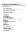
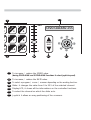
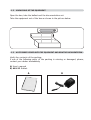
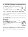
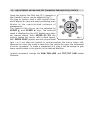
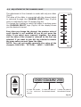
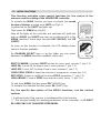
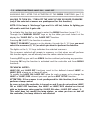
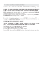
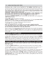
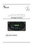
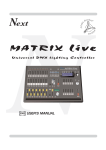
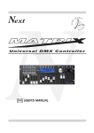
Next
PROGRAMMABLE
GB
DMX
USER’S MANUAL
CONTROLLER
INDEX
We congratulate you on your purchase of NAVIGATOR 2012.
Before proceeding of the use of this product it should be necessary to read
carefully the following user’s manual to install it correctly and to make the
most of its potentialities.
Sets of the equipment
1.1 Description of the front panel
1.2 Unpacking of the equipment
1.3 Acessories issued with the equipment and relative documentation
Description of the rear panel and installation
2.1 Description of the rear panel
2.2 DMX 512 output connection
2.3 Input connection for power supply
2.4 Connection of the ballast to the electric system
Use of the equipment - modes of operation
3.1 PROGRAM mode
3.2 SCENE mode
3.3 MAN + PROGRAM mode
3.4 MAN + SCENE mode
Use of the equipment - main functions
4.1 Adjustment of the RATE speed
4.2 Adjustment of the SPEED speed
4.3 Adjustment of the PAN and TILT channels through the Joystick
4.4 Adjustment of the channels
4.5 MUSIC function
Use of the equipment - secondary functions
5.1 MEM function
5.2 COPY function
5.3 LENGTH function
5.4 REPEAT function
5.5 BLACKOUT function
Example of working - creation of a program
6.1 Creation of a program
Example of working - MENU functions
7.1 MENU functions
7.2 MENU: RESET SCANNERS
7.3 MENU: LAMP ON / LAMP OFF
7.4 MENU: CLEAR PROGRAM/SCENE
7.5 MENU: EDIT SETUP
7.6 MENU: LOAD LIBRARY
1.1
DESCRIPTION OF THE FRONT PANEL
1
2
PROG
3
SCENE
POWER
5
6
MUSIC
SHIFT
( ESC )
( OK )
M
1
5
SPEED
4
M
E
RATE
MAN
M
7
E
N
U
9
8
1
To activate/deactivate the controller storing all the settings.
2
To activate the PROGRAM mode.
3
To activate the SCENE mode.
4
To activate the PROG+MAN / SCENE+MAN function.
5
To activate the MUSIC function for the change of the scene to the beat of the music.
(during MENU functions it becomes ESC key)
6
To activate the SHIFT function and select the second function of 1/12 keys.
(during MENU functions it becomes OK key)
C
O
P
Y
11
9
6
G
3
RE
PE
7
11
9
4
8
BL
A
O
CK
CHANNEL
SELECT
UT
12
0
10
➠
➠
➠➠
0
CH20 COLOUR2 255
➠
➠
➠
2
N
255
AT
➠
LE
TH
12
13
7
To increase / reduce the SPEED value.
(during PROG+MAN and SCENE+MAN functions it select joystick speed)
8
To increase / reduce the RATE value.
9
To select a program / scene / scanner depending on the working function.
10
Slider: it changes the value from 0 to 255 of the selected channel.
11
Display LCD, it shows all the informations on the controller functions.
12
To select the channel on which the slider acts.
13
Joystick: it allows an easy positioning of the scanners.
1.2
UNPACKING OF THE EQUIPMENT
Open the box; take the ballast and the documentation out.
Take the equipment out of the box as shown in the picture below.
1.3
ACCESSORIES ISSUED WITH THE EQUIPMENT AND RELATIVE DOCUMENTATION
Verify the contents of the packing.
If one of the following parts of the packing is missing or damaged, please,
contact your dealer immediately.
A) User’s manual
B) AN-612 Ballast
A
B
2.1
DESCRIPTION OF THE REAR PANEL AND INSTALLATION
POWER INPUT
12 VDC - 2 W
1
+VDC
1
3
COMMON
2
3
DMX 512
OUTPUT
PUSH
5
1
4
2
AUDIO IN
(0 dB)
1
5
4
2
3
2
3
1 = COMMON
2 = DATA 3 = DATA +
4 = n.c.
5 = n.c.
1
Standard DMX 512 signal OUTPUT with a 5-pin cannon connector.
2
0 dB audio signal INPUT with a mono/stereo jack connector.
3
12 Vdc power INPUT with a 3-pin cannon connector.
2.2
DMX 512 OUTPUT CONNECTION
Make sure you are using shielded twisted cables suitable for the
transmission of the DMX 512 signal with connectors of good quality and
connection as shown on the side of the connector.
Plug the 5-pin cannon connector coming from the projectors completly in the
DMX 512 output 1
Use the “push” safety hook to disconnect it and than extract it gently.
ATTENTION: the shielded part of the cable must never be connected to the
ground of the electrical system as this could cause faults during the
working of the controller.
The “start” channel of the controller is channel n°1, for other DMX address
you can follow the tabel below.
SCANNER N° 1
DMX address:
1
SCANNER N° 7
DMX address:
121
SCANNER N° 2
DMX address:
21
SCANNER N° 8
DMX address:
141
SCANNER N° 3
DMX address:
41
SCANNER N° 9
DMX address:
161
SCANNER N° 4
DMX address:
61
SCANNER N° 10
DMX address:
181
SCANNER N° 5
DMX address:
81
SCANNER N° 11
DMX address:
201
SCANNER N° 6
DMX address:
101
SCANNER N° 12
DMX address:
221
2.3
INPUT CONNECTION FOR POWER SUPPLY
Plug the 3-pin cannon connector of the ballast completly in the power
input 3
Use the “push” safety hook to disconnect it and extract it gently.
ATTENTION: do not use ballast different from the one supplied, it could
cause serious damages at the internal circuitation.
Do not connect the 3-pin cannon connector in other appliances, it has been
studied to be used only in this controller.
2.4
CONNECTION OF THE BALLAST TO THE ELECTRIC SYSTEM
MAKE SURE THAT VOLTAGE AND POWER FREQUENCY CORRESPOND TO
WHAT IS REPORTED ON THE BALLAST PLATE.
The supplied ballast has a plug, therefore you should only plug it in the socket.
Press POW key to verify the correct installation.
If pressing the POW key no leds light up, please check if there is tension in the
electric socket or check the connection between ballast-controller and
ballast-electric socket.
If the problem persists, please consult your dealer.
3.1
PROGRAM MODE
This function allows to activate a program or a range of programs
Pressing PROG key the PROGRAM function is activated
(Fig.1)
The red led of PROG key will light up to indicate the activation
of this function.
The LCD display indicates the program working at moment.
If no program is activated, the controller goes in BLACKOUT
MODE and the LCD display indicates “BLK”.
PROG
Fig. 1
Press 1÷12 keys to activate/deactivate the programs which will be performed
in succession.
All selected programs have a lighted up led, while the active program has a
flashing led.
N.B. Each program is repeated for a number of times established through the
REPEAT function (see par. 5.4)
The speed of change between the scenes can be controlled by RATE ▲ and
RATE ▼ keys (see par. 4.1).
The relation between the movement of the scanners and the pause between
scenes is controlled by SPEED ▲ and SPEED ▼ keys (see par. 4.2).
When the maximum or minimum speed is reached the led of the SHIFT key flashes.
3.2
SCENE MODE
This function allows to see one of the 12 scenes of the program in action.
N.B. If no programs are selected the SCENE function is not active.
Pressing SCENE key the SCENE function is activated (Fig.2)
The red led of SCENE key will light up to indicate the
activation of this function.
When you pass from PROGRAM mode to SCENE mode, the
scene active in that moment is selected.
The LCD display indicates the scene working at moment.
If no scene is activated, the controller goes in BLACKOUT
MODE and the LCD display indicates “BLK”.
SCENE
Fig. 2
Press any 1÷12 keys to activate/deactivate the scene.
The speed of change between the scenes can be controlled by RATE ▲ and
RATE ▼ (see par. 4.1).
When the maximum or minimum speed is reached the led of the SHIFT key flashes.
N.B. In this function SPEED ▲ and SPEED ▼ keys are not activated
3.3
MAN+PROGRAM MODE
This function allows to activate manually one or more scanners while the
not selected ones go on performing the PROGRAM function.
When PROGRAM function is working, pressing MAN (Fig.3)
key the MAN+PROGRAM function is activated.
The red led on PROG and MAN keys will light up to indicate
the activation of this function.
MAN
Pressing MAN key once more you come back in PROG mode.
Fig. 3
Press 1÷12 keys to activate/deactivate the scanners manually controlled.
The selected scanners (with ligthed up led) do not follow anymore the
program, but are manually controlled through the joystick, the selection of the
channel and the slider.
Once it has been deactivated, the scanner performs again the working
program.
3.4
MAN+SCENE MODE
This function allows to activate manually one or more scanners to create or
to modify a scene.
When SCENE function is working, pressing MAN key
(fig. 4) the MAN+SCENE function is activated.
The red led of SCENE and MAN keys will light up to indicate
the activation of this function.
Pressing MAN key once more you can come back to the
SCENE mode.
MAN
Fig. 4
Pressing one of the 1÷12 keys the scanner manually controlled is activated.
To select more scanners press in sequence 1÷12 keys very quickly. The
selected scanners (with lighted up led) can be manually controlled using the
joystick, the channel selection and the slider.
Once another scanner has been selected, the previous one keeps all made
sets.
4.1
ADJUSTMENT OF THE RATE SPEED
The adjustment of the RATE is activated only in PROG and SCENE function.
The two settings of the value are indipendent as passing from one mode to
the other you find the same previous set value.
The RATE value is simply the time that the scene takes to
arrive at the end, therefore it is also the speed of the change
between the scenes.
Using the RATE ▲ key (Fig.5) the speed increases, i.e. the
scene takes less time to arrive at the end position, while
using the RATE ▼ key (Fig.5) the speed reduces up to a value
of 30 seconds to end the scene.
RATE
When the maximum and minimum speed is reached the led
on the SHIFT key flashes.
Fig. 5
4.2
ADJUSTMENT OF THE SPEED
The SPEED adjustment is activated only in PROG function, while it is
deactivated in SCENE and MUSIC function.
The SPEED value is the ratio between the time of the
scanner’s movement and the total length of the scene.
The SPEED value are 10: from 10% to100%.
Using the SPEED ▲ key (Fig.6) the speed increases and the
time of pause, too, while using the SPEED ▼ key (Fig.6) the
speed reduces and the movement becomes continuous,
without pauses.
For instance, if you set a RATE of 30 seconds and the SPEED
has the minimum value, the scene has a length of 30 seconds
and the movement of the mirror has a length of 30
seconds,too. If you set the previous RATE value but you
increase the SPEED value up to 50%, the length of the scene
is always 30 seconds instead the movement of the mirror has
a length of 15 seconds (as the speed is doubled in comparison
with the previous one) and a pause of 15 seconds.
When the maximum and minimum speed are reached the led
on the SHIFT key flashes.
SPEED
Fig. 6
4.3
ADJUSTMENT OF PAN AND TILT CHANNELS THROUGH THE JOYSTICK
➠
➠
➠
Using the joystick the PAN and TILT channels of
the scanner’s mirror can be adjusted (Fig.7).
The type of joystick used is with central return
and it allows an easy and exact positioning even
thanks to the sophisticated software of
management.
The speed of the mirror can be adjusted by
SPEED ▲ and SPEED ▼ keys. The selected
speed is displayed on the LCD display every time
we change speed. With SPEED 01/09 the
joystick moves the mirror with a fixed speed,
Fig. 7
with SPEED PROP joystick become proportional
type, i.e. if you keep the joystick in central position the mirror keeps still;
whereas the more you move it away from the centre the more the movement
of mirror increases. To make a movement of a step it will be enough to give
some small strokes to the joystick in the desired direction.
➠
➠
➠➠
➠
Joystick movement change the PAN/PAN LOW and TILT/TILT LOW output
channels.
4.4
ADJUSTMENT OF THE CHANNEL VALUE
The adjustment of the channels is made with only one slider
(Fig.8).
The value of the slider is connected with the channel which
is selected through the CHANNEL SELECT keys (Fig.9a)
and it is indicated by the LCD display (Fig.9b).
To change the channel on which the slider is working press
the CHANNEL SELECT keys (Fig.9a) till the display shows
you the desired channel.
255
Every time you change the channel, the previous value of
each channel is not modified till you do not move the
slider. If you select more scanners together, the name
and the value of the channel is referred to the first one
selected. If you want to give ALL the selected scanners
the same value you must move the slider.
NOTE: You can not modify manually the value of the
channels: PAN LOW / TILT LOW / LAMP / LAMP-RES
0
Fig. 8
CH20 COLOUR2 255
CHANNEL
SELECT
It shows the number
of the selected
channel
Fig. 9a
It shows the name of
the selected channel
It shows the value of
the selected channel
Fig. 9b
4.5
MUSIC FUNCTION
This function performs the program to the rhythm of the music,
synchronising the change of the scene with the bass beats.
Pressing the MUSIC key (Fig.10) the MUSIC function is activated.
This function can be activated only during the PROGRAM
and MAN+PROGRAM mode.
MUSIC
The green led on the key lights up to indicate the starting of
this function.
Fig. 10
Using this function the change of the scenes occurs only when the musical
sensor receives the audio signal from the rear audio input or from the built-in
microphone. (If to the rear input you connect a jack the built-in microphone is
deactivated).
The speed of the change between the scenes is controlled by the RATE ▲ and
the RATE ▼ keys: when the maximum or minimum speed is reached the led
on the SHIFT key flashes.
Usually, during the MUSIC function, the speed of the change between the
scenes should be not so low otherwise the movement of the scanner will be
very slow.
N.B. In this function the SPEED ▲ and the SPEED ▼ keys are deactivated.
The internal music sensor has an automatic gain adjustment which allows to
have a signal level good for the NAVIGATOR 2012 working.
The input music signal is a 0dB mono/stereo so it could be taken from sound
sources like Mixer, CD, Dat etc.
N.B. Only one channel of the jack stereo connector placed on the rear of
the controller is connected to the music sensor.
IT IS ABSOLUTELY FORBIDDEN TO CONNECT TO THIS INPUT ANY POWER
SIGNALS FOR ACOUSTIC SPEAKER COMING FROM AMPLIFIED MIXER OR
AMPLIFIER!!
5.1
MEM FUNCTION
--------------------------------------------------------------------------------------------------------------------THIS FUNCTION IS AVAILABLE ONLY IN MAN MODE
--------------------------------------------------------------------------------------------------------------------This function stores in a scene the present situation of the scanners.
To activate the MEM function you have to activate the second
function of the keys pressing once SHIFT key (Fig.11).
(a yellow led on the SHIFT key lights up).
If the led on the SHIFT key does not light up, the MEM
function cannot be activated as no scene has been selected
previously.
SHIFT
Fig. 11
Then press 1/MEM key (Fig.12).
Now, the settings of the channels and the PAN and TILT
position of all scanners are stored in a permanent way in the
selected scene of the active program.
M
E
M
1
If all the operations have been done correctly, the mode of
working pass from MAN mode to SCENE mode so that any
other scene can be selected, created or modified.
5.2
Fig. 12
COPY FUNCTION
--------------------------------------------------------------------------------------------------------------------THIS FUNCTION IS AVAILABLE ONLY IN SCENE MODE
--------------------------------------------------------------------------------------------------------------------This function allows to copy the present active scene in another one.
To activate the COPY function you have to activate the second
function of the keys pressing once SHIFT key (Fig.13).
(a yellow led on the SHIFT key lights up).
If the led on the SHIFT key does not light up, the COPY
function cannot be activated as no scene has been selected
previously.
SHIFT
Fig. 13
Then press 2/COPY key (Fig.14).
Now, the led of the active scene is flashing; press any 1÷12
keys to select the scene of destination.
Pressing a different key the copy function is cancelled.
If all the operations have been done correctly, the active
scene becomes now the scene of destination.
C
O
P
Y
2
Fig. 14
5.3
LENGTH FUNCTION
--------------------------------------------------------------------------------------------------------------------THIS FUNCTION IS AVAILABLE ONLY IN PROG MODE
--------------------------------------------------------------------------------------------------------------------This function allows to choose the length of the active program, or rather
the last performed scene of the program.
To activate the LENGTH function you have to activate the second
function of the keys pressing once SHIFT key (Fig.15).
(a yellow led on the SHIFT key lights up).
If the led on the SHIFT key does not light up, the LENGTH
function cannot be activated as no program has been
selected previously.
SHIFT
Fig. 15
Then press 3/LENGTH key (Fig.16).
Now, the led of the the selected length is flashing; press any
1÷12 keys to select a new length of the program.
Pressing a different key the operation is cancelled.
LE
N
G
TH
3
Fig. 16
5.4
REPEAT FUNCTION
--------------------------------------------------------------------------------------------------------------------THIS FUNCTION IS AVAILABLE ONLY IN PROG MODE
--------------------------------------------------------------------------------------------------------------------This function allows to select the number of repetitions for each program.
To activate the REPEAT function you have to activate the second
function of the keys pressing once SHIFT key (Fig.17).
(a yellow led on the SHIFT key lights up).
If the led on the SHIFT key does not light up, the REPEAT
function cannot be activated as no program has been
selected previously.
SHIFT
Fig. 17
Then press 4/REPEAT key (Fig.18).
Now, the led corresponding to the selected number of
repetitions is flashing; press any 1÷12 keys to select a new value.
Pressing a different key the operation is cancelled.
R
E
A
PE
T
4
Fig. 18
5.5
BLACKOUT FUNCTION
This function allows to black-out all the scanners.
Press 12/BLACKOUT key to start again the normal working.
To activate the BLACKOUT function you have to activate the second
function of the keys pressing once SHIFT key (Fig.19).
(a yellow led on the SHIFT key lights up).
SHIFT
Then press 12/BLACKOUT key (Fig.20).
Now, all leds of the controller are switched off, while the led
on 12/BLACKOUT key is flashing.
Pressing 12/BLACKOUT key (Fig.20) the controller returns
to the previous working.
Fig. 19
BL
A
O
CK
UT
12
Fig. 20
6.1
EXAMPLE OF WORKING - CREATION OF A PROGRAM
A program is a range of scenes (max 12) performed in succession. To create
(or to modify) a program follow all steps listed below:
1) If the controller is switched off, switch it on pressing POW key.
2) Press PROG key to activate the PROGRAM function.
(the red led on the same key will light up).
3) Using 1÷12 keys select only the program that you want to modify.
(only one program is flashing).
4) Press SCENE key to activate the SCENE function.
(the red led on the same key will light up).
5) Using 1÷12 keys select the scene that you want to modify.
6) Press MAN key to activate the MAN+SCENE function.
(the red leds on the MAN and SCENE keys will light up).
7) Using 1÷12 keys select one or more scanners and modify the position
with the joystick and the sets of the channels with the CH.SEL. key
and the slider.
8) Once the scanners have been selected and the scene has been completed,
it can be stored using the MEM function: press SHIFT key and than
1/MEM key (see par. 5.1).
9) Now the controller is again in the SCENE function in order that you can
select another scene or copy the scene already done in another one (see par. 5.2)..
10) Once the creation of the scenes has been finished press PROG key to
come back to the PROGRAM function.
(the red led on the same key will ligth up).
11) Finally, you should set the length of the program using the LENGTH
function: press once SHIFT key than the 3/LENGTH key followed by
the number of the last stored scene (see par. 5.3).
The program is finished; to create or modify others repeat again all the above
steps.
NOTES
7.1
MENU FUNCTIONS
This function activates some special functions for the control of the
scanners and the setting of the NAVIGATOR controller.
To activate the MENU function you have to activate the second
function of the keys pressing once SHIFT key (Fig.21).
(a yellow led on the SHIFT key lights up).
Then press 9/MENU key (Fig.22).
SHIFT
( OK )
Now all the lights of the controller are switched off, while the
leds on MUSIC and SHIFT keys stay on to indicate that in the
MENU functions these keys become ESC (MUSIC) and OK
(SHIFT).
As soon as this function is activated, the LCD display shows
the first function available..
By CHANNEL SELECT keys or by the slider you can select
between the MENU functions available, which are:
Fig. 21
M
E
N
U
9
Fig. 22
RESET SCANNER: It activates RESET function for one or more scanners * (par.7.2)
LAMP ON: It turns ON the lamp of one or more scanners * (par.7.3)
LAMP OFF: It turns OFF the lamp of one or more scanners * (par.7.3)
CLEAR PROG/SCENE: It clears the contents of a program or a scene (par.7.4)
EDIT SETUP: It allows to modify all the active SETUP parameters ** (par.7.5)
LOAD LIBRARY: It loads a SETUP from internal scanner library ** (par.7.6)
To exit from MENU function press ESC (MUSIC) key.
To activate the selected function press OK (SHIFT) key.
For the specific description of the MENU functions, see the related
sections.
* It will work only if the scanner is predisposed for this function.
** This function modify the working parameters of the controller, so IT MUST
BE USED ONLY BY QUALIFIED PERSONNEL.
7.2
MENU FUNCTIONS: RESET SCANNER
---------------------------------------------------------------------------------------------------------------------
AVAILABLE ONLY AFTER THE ACTIVATION OF THE MENU FUNCTIONS (par.7.1)
--------------------------------------------------------------------------------------------------------------------ALLOWS TO RESET ONE OR MORE SCANNERS.
(only if the selected scanner are predisposed for this function).
This function must be performed when the scanners lose synchronization or
they don’t perform the commands of the controller in a correct way.
To activate this function you have to enter the MENU functions (v.par.7.1).
Through the CHANNEL SELECT keys or by the slider you must select on the
display the “RESET SCANNER” function.
Pressing OK (SHIFT) the function is entered.
“SELECT SCANNER” appears on the display, through the 1/12 keys you must
select the scanners (1/12) on which you want to perform the function.
The lights on the 1/12 keys indicates the selected scanners.
The scanners selected will remain in memory, so that when we will perform
this function again, we will already have the same selected scanners.
Pressing ESC key you exit from MENU functions without performing any operation.
Pressing OK key the RESET function is activated for 6 seconds.
TECHNICAL NOTES:
RESET function sends for 6 seconds a defined reset value to all the 20
channels of the selected scanners.
To modify the reset value for each channel you must perform EDIT SETUP
function.
ATTENTION: If the scanner is not predisposed for this function, it will never
perform a reset.
7.3
MENU FUNCTIONS: LAMP ON / LAMP OFF
---------------------------------------------------------------------------------------------------------------------
AVAILABLE ONLY AFTER THE ACTIVATION OF THE MENU FUNCTIONS (par.7.1)
--------------------------------------------------------------------------------------------------------------------ALLOWS TO TURN ON / TURN OFF THE LAMP OF ONE OR MORE SCANNERS.
(only if the selected scanners are predisposed for this function).
NOTE: If the lamp is “discharge” type and it is still hot, before its lighting you
will need to wait that it gets cold.
To activate this function you have to enter the MENU functions (v.par.7.1).
Through the CHANNEL SELECT keys or by the slider you must select on the
display the “LAMP ON” or the “LAMP OFF” function.
Pressing OK (SHIFT) the function is entered.
“SELECT SCANNER” appears on the display, through the 1/12 keys you must
select the scanners (1/12) on which you want to perform the function.
The lights on the 1/12 keys indicates the selected scanners.
The scanners selected will remain in memory, so that when we will perform
this function again, we will already have the same selected scanners.
Pressing ESC key you exit from MENU functions without performing any operation.
Pressing OK key the function is activated and the controller exit from MENU
functions..
TECHNICAL NOTES:
LAMP ON and LAMP OFF functions send to the defined channel LAMP or
LAMP/RES a lamp on or lamp off value.
To modify the LAMP ON/LAMP OFF value for each scanner or to change the
LAMP or LAMP/RES channel you must perform EDIT SETUP function.
ATTENTION: If the scanner is not predisposed for this function, it will never
perform a lamp control.
As soon as turn the controller is turned on and if you do not perform LAMP
ON or LAMP OFF functions, the LAMP or LAMP/RES channel are forced
with an hysteresys value equal to: (LAMP ON value - LAMP OFF value) /2.
This value does not modify the lamp status, so when you turn on and off
the controller, the lamp status is not affected.
7.4
MENU FUNCTIONS: CLEAR PROG/SCENE
---------------------------------------------------------------------------------------------------------------------
AVAILABLE ONLY AFTER THE ACTIVATION OF THE MENU FUNCTIONS (par.7.1)
---------------------------------------------------------------------------------------------------------------------
ALLOWS TO CLEAR A PROGRAM IF ENTERED FROM PROGRAM MODE OR TO
CLEAR A SINGLE SCENE IF ENTERED FROM SCENE OR SCENE+MAN MODE.
NOTE: activating this function while the controller is performing PROGRAM
mode a whole program is cleared (12 scenes).
Activating this function while the controller is performing SCENE or
SCENE+MAN mode a single scene is cleared.
To activate this function you have to enter the MENU functions (v.par.7.1).
Through the CHANNEL SELECT keys or by the slider you must select on the
display the “CLEAR PROG/SCENE” function.
Pressing OK (SHIFT) the function is entered.
“SELECT PROGRAM” or “SELECT SCENE” appears on the display, through
the 1/12 keys you must select the program/scene (1/12) to clear.
The lights on the 1/12 keys indicates the selection.
On the display “CLEAR ? ESC/OK” appears.
Pressing OK key the program/scene will be cleared.
Pressing ESC key you exit from MENU functions without performing any operation.
5.1
7.5
DESCRIZIONE
MENU FUNCTIONS:
PANNELLO
EDIT SETUP
COMANDI
---------------------------------------------------------------------------------------------------------------------
AVAILABLE ONLY AFTER THE ACTIVATION OF THE MENU FUNCTIONS (par.7.1)
---------------------------------------------------------------------------------------------------------------------
This function allows to modify manually the name of each channel and its parameters (reset
1
5
value, blackout
value, hard/soft cross) it also allows
to assign6 special functions to the
channel (pan/tilt,pan low/tilt low, lamp control).
ATTENTION ! MODIFICATION OF THE SETUP PARAMETERS, IF NOT EFFECTED IN AN
APPROPRIATE WAY, PREVENTS THE CONNECTED SCANNERS TO WORK CORRECTLY.
M
MUSIC
SHIFT
O
To activate this function2you havePROG
to enter the MENU
functions
(v.par.7.1). M
C
( ESC )
( OK )
1 the
POWER
Through
the CHANNEL SELECT keys or by the slider you must select on the display
“EDIT SETUP” function.
E
Pressing OK (SHIFT) the function is entered.
“SELECT SCANNER” appears
on
the display; through the 1/12 keys you must select
SCENE
3
5
the scanners (1/12) on which you want to perform the function.
The lights on the 1/12 keys indicates the selected
scanners.RATE
SPEED
Pressing OK key the function is activated.
U
N
E
NOTE: The displayed SETUP
modify is that of the FIRST SCANNER SELECTED.
4 for theMAN
M
9
If you select more scanners even of different models, when modifications will be memorized
ALL THE SELECTED SCANNERS WILL HAVE THE SAME SETUP.
When the name of the scanner appear on the display (setup name), you can select the channel on
7
8
which act. Through the CHANNEL SELECT keys or by the slider you can display sequentially the
name of all the 20 channels, returning back to the first position we can display the name of the
scanner again.
TO MODIFY SCANNER NAME
Through the CHANNEL SELECT keys or by the slider select the name of the scanner on the display.
-> Press OK to modify the name (a line under the first letter appears); through the CHANNEL
1
Attiva
/ disattiva
la you
centralina
memorizzando
tuttepress
le impostazioni
SELECT
keys or
by the slider
can select
the desired letter,
OK to select next letter to
modify. When you finish the modification of the last letter (16 total) you return back to the
2
Attiva il modo di funzionamento PROGRAM
channels selection (the name of the scanner is displayed without the line under the letters).
3
Attiva il modo di funzionamento SCENE
TO MODIFY THE NAME AND THE PARAMETERS OF THE CHANNEL
4
Attiva la funzione PROG+MAN / SCENE+MAN
NOTE: to exit from this function without modification read “TO EXIT FROM EDIT SETUP
5
Attiva la funzione MUSIC per il cambio della scena a ritmo di musica
FUNCTION” section.
(durante le funzioni MENU esegue ESC)
Through the CHANNEL SELECT keys or by the slider select the number of the channel to modify
6
Attiva la funzione SHIFT per selezionare la seconda funzione dei tasti 1/12
-> Pressing OK the arrow “>” is positioning on the left of the name of the channel and “*”
(durante
le funzioni
MENU
esegue
OK)is the one selected at the moment.
appears,
which shows
that the
channel
displayed
Through the CHANNEL SELECT keys or by the slider you can substitute this channel with one
among those memorized. Putting the slider on 0 position you display the channel actually active “*”,
putting the slider on 255 position *CUSTOM* appears on the display (only now we can write
manually the name of the channel, pressing OK a line appears under the first letter, through the
CHANNEL SELECT keys or by the slider you select the letter, pressing OK you select the next
letter, until the end of the name).
P
-> Pressing OK the channel displayed becomes active and we start to modify the channel
parameters.
The controller uses these special channels for predefined functions, you must use them for
the specific functions assigned to them.
NOT USED -> Not used channel.
-> Pan channel (SOFT CROSS/HARD CROSS).
PAN LOW -> Pan channel LOW.
TILT
-> Tilt channel (SOFT CROSS/HARD
CROSS).
255
TILT TLOW
->
Tilt
channel
LOW.
T
H
E A control channel.
G
LAMP
-> Lamp
P
N
E
LE
LAMP/RES
LAMP.
3 -> RLike 4
9PAN
11
CH20 COLOUR2 255
➠
➠
➠
The value change between two scenes can be immediate (HARD CROSS) or gradual (SOFT
CROSS).
-> Through the CHANNEL SELECT keys or by the slider you can modify change mode, HARD
CROSS7or SOFT CROSS.
8 (except for the special function channels, in which you jump directly to
modification of the BLKOUT value).
➠
➠
➠➠
0
➠
CHANNEL
-> Press OK to modify
“BLKOUT VAL” that is theSELECT
value of the channel when the BLACKOUT
T
U
function is active (par.5.5).
KO
A C (unchanged) value or 0 / 255 value. The === value is selected putting the
You can select L===
B 12
slider 11
to 0 and it allows
to maintain unchanged
the output value (no blackout for this channel).
0
-> Press OK to modify “RESET VAL” that is the value of the channel when the MENU: RESET
function is active (v.par.7.2).
9
10
12
13
You can select === (unchanged) value or 0 / 255 value. The === value is selected putting the
slider to 0 and it allows to maintain unchanged the output value (no reset for this channel).
Only if the LAMP or LAMP/RES channel is selected; press OK to modify LAMP ON value. Press
OK again to modify LAMP OFF value.
-> Pressing OK again you return back to the channels selection, and the arrow “>” is positioned
on the left of the channel number.
Now you can select another channel for the modification.
NOTE:
Pressing /
OKdiminuisce
key withoutil moving
CHANNEL
7
Aumenta
valore di
SPEED SELECT keys and the slider you can scroll
between
channel
parameters
without
any
modification.
(durante le PROG+MAN e SCENE+MAN seleziona la velocità del joystick)
TO STORE ALL THE MODIFICATIONS, READ THE SECTION BELOW.
8
Aumenta / diminuisce il valore di RATE
9
TO EXIT
FROM/ EDIT
SETUP
FUNCTION
Seleziona programma
/ scena
scanner
a seconda
della funzione attiva
To exit
from thisil function
youcui
need
to press
ESC key when you are in the channel selection
10
Seleziona
canale su
agisce
lo slider
when the arrow “>” is on the left of the number of channel (pressing ESC key when you are
11
Display
LCD, parameters,
visualizza le you
informazioni
relative
funzionamento
della
modifying
channel
return back
to thealchannels
selection,
so centralina
you have to
press ESC key again).
12
Potenziometro slider per variare il valore del canale selezionato da 0 a 255
When “SAVE ? ESC/OK” appears on the display ; Pressing OK all the modifications ARE
13
Joystick
che permette
facile posizionamento
scannerfunction.
STORED
IN MEMORY
and theuncontroller
exits from the degli
EDIT SETUP
Pressing ESC, “EXIT ? ESC/OK” appears on the display; if you want to exit from this function
WITHOUT STORING THE MODIFICATIONS press OK, otherwise press ESC to return to the
channel selection.
NOTE: EDIT SETUP function acts on the controller’s memory and DOES NOT modify the
library of scanner setups.
7.6
MENU FUNCTIONS: LOAD LIBRARY
---------------------------------------------------------------------------------------------------------------------
AVAILABLE ONLY AFTER THE ACTIVATION OF THE MENU FUNCTIONS (par.7.1)
--------------------------------------------------------------------------------------------------------------------ALLOWS TO LOAD A SETUP FROM LIBRARY AND STORE IT IN MEMORY.
To activate this function you have to enter the MENU functions (v.par.7.1).
Through the CHANNEL SELECT keys or by the slider you must select on the
display the “LOAD LIBRARY” function.
Pressing OK (SHIFT) the function is entered.
“SELECT SCANNER” appears on the display, through the 1/12 keys you must
select the scanners (1/12) on which you want to perform the function.
The lights on the 1/12 keys indicates the selected scanners.
Pressing ESC key you exit from MENU functions without performing any operation.
Pressing OK key the function is activated.
The display shows the first scanner in the library, through the CHANNEL
SELECT keys or by the slider you can select the right type of scanner (or an
equivalent) from the library.
Once selected the scanner, pressing OK appears on the display
“SAVE ? ESC/OK”.
Pressing OK the SETUP of the selected scanner is loaded in the memory of
the controller and activated for all the selected scanner.
Pressing ESC appears on the display “EXIT ? ESC/OK”; if you want to exit
from this function WITHOUT ANY MODIFICATION press OK key, otherwise
pressing ESC key you return back to the selection of the scanner.
NOTE: If inside the SETUP library there isn’t your scanner or a compatible
type, you must configure manually the SETUP of the controller, using the EDIT
SETUP function (par.7.5).
The SETUP LIBRARY is a range of SETUP (scanner) that can not be modified,
but only read.
Through LOAD LIBRARY function you can copy the SETUP of the scanner
from the library to the internal memory of the controller.
To modify a SETUP you must store it in memory through the LOAD LIBRARY
function and after modify it through the EDIT SETUP function.
TECHNICAL FEATURES OF NAVIGATOR 2012
Technical features:
Number of scanners controlled separately: 12
Number of channels for each scanner: 20
Number of stored programs: 12
Number of scenes for each program: 12
Total number of scenes: 144 (12 programs x 12 scenes)
Positioning way of the mirror: through a Joystick (fix or proportional mirror speed)
Channel features: Pan-Tilt 8/16 bit - Hard/Soft cross - Reset - Lamp
Setup: Load from internal library or manual setup.
Technical features: output signal
Kind of output signal: DMX512/ 1990
Output connector: 5-pin cannon connector
Max number of scanners connected to the DMX output: 32
Number of DMX channels: 240 (20 ch. x 12 scanners)
Technical features: storage of program and settings
Kind of storage / size: FLASH memory 2 Mbit
Data maintenance without power supply: > 40 years
Climatic condition for the use
Humidity: 35% ÷ 80%
Temperature: 5 ÷ 50 °C
Power supply
Voltage/current: 12 Vdc / 240 mA
Technical features: audio input
Source: Inside through a built-in microphone / outside through a stereo jack
Sensitivity / input impedance: 0 dB (775 mV) / 50 Kohm
Kind of level adjustment: Automatic
Dimensions and weight
Dimension (W x L x H) / Weight: 482 x 88 x 65 mm (2U rack) / 1,6 Kg.
CODEM MUSIC S.r.l. - Via Del Vallo, 110 - 61100 PESARO - ITALY
Tel. +39 0721 204357- Fax +39 0721 203554
http://www.codemmusic.com - E-mail: [email protected]
All rights reserved. No parts of this document can be copied, photocopied or reproduced without
the prior written permission of the CODEM MUSIC s.r.l.
No responibility is taken for possible inaccuracies or mistakes.
The CODEM MUSIC s.r.l. reserves the right to make any alterations or aesthetics changes of this
product that seem necessary at any time and for whatever reason.
The CODEM MUSIC s.r.l. takes no responsibility for the use or for the application of this product.