1
SAFETY PRECAUTIONS
(Be sure to read these instructions before using the product.)
Before using this product, read this manual and the relevant manuals introduced in this manual carefully
and handle the product correctly with full attention to safety.
Note that these precautions apply only to this product.
In this manual, the safety instructions are ranked as "DANGER" and "CAUTION".
DANGER
Indicates that incorrect handling may cause hazardous conditions, resulting in
death or severe injury.
CAUTION
Indicates that incorrect handling may cause hazardous conditions, resulting in
minor or moderate injury or property damage.
Note that failure to observe the
CAUTION level instructions may also lead to serious results
depending on the circumstances.
Be sure to observe the instructions of both levels to ensure personal safety.
Please keep this manual in accessible place and be sure to forward it to the end user.
[Test operation precautions]
DANGER
When testing the operation (e.g. turning bit devices ON/OFF or changing a current word device
value, a current or set timer/counter value, or a current buffer memory value), thoroughly read the
relevant manual to fully understand the operating procedures. When testing, never change the data
of the devices that control the operation essential for the system.
Faulty output and malfunction may result in an accident.
A-1
CAUTIONS FOR USING THIS SOFTWARE
1. Error messages displayed while starting and editing
"Operation will be terminated because of insufficient memory. Would you like to stop?"
If the above message appears, close other running application software or reboot Windows
in order to
secure enough free space of the hard disk.
2. GT Designer2 and GOT display
(a) Cautions for displaying straight line other than full line (dotted line, for example) in bold.
When straight line other than full line is drawn in bold, the line may not be displayed with its actual line
width on a personal computer. However, it will be displayed correctly on GOT. This phenomenon does
not mean data problem.
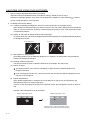
(b) Display of end points of straight line/line freeform/polygon
As shown below, the end points of straight line/line freeform/polygon are displayed differently between
GT Designer2 and GOT.
On GOT
On GT Designer2
(c) Start position for filling patterns
Some filling patterns may be differently displayed. For example, the start position may be different
between GT Designer2 and GOT.
(d) Drawing of different type lines
The length of the dots varies in different dotted lines (for example: the chain lines).
(e) Display of object
The display position of the memory data display in graph function is different between GT
Designer2 and GOT.
Even if the display-start-line of a comment has been set, the comment will be displayed from the
first line on GT Designer2.
(f)
Display magnification
When display magnification is changed, the connected lines or figures may be separated or the
filled-paint may be out of outline of the figure.
However, if they are displayed correctly on the preview screen, they will appear correctly on GOT as
well.
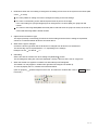
Example: When filled-paint is out of the outline.
Display magnification: 200%
Display magnification: 100%
Position of Paint mark may be shifted and the
filled-paint may exceed the outline of the figure.
A-2
3. Restrictions when the color setting is changed to the setting of less colors in the system environment (256
colors
2 colors)
The color palette for setting color will be changed according to the new settings.
The color on the drawing screen will be kept the same as prior to the change.
If the color setting for a [red] rectangle-figure is changed to the 2 colors (B/W), the [red] color will
remain.
The colors of the image data (BMP format file) will be reduced when the project is stored, the screen is
closed and that image data is double-clicked.
4. Object function and device type
The object (bit lamp or word lamp),for which bit device setting and word device setting are separated,
cannot be converted between bit device and word device.
5. When device type is changed
Confirm the device type when the set bit device is changed from bit device into word device.
The device flag may be represented as "??", depending on the settings.
Example: D0. b0
D0 D0.b5
??
6. OS setting
Set the font size as "Small Font" when setting OS (Windows ) screen.
The GT Designer2 dialog box cannot be displayed correctly if the font size is set as "Large font".
7. When the toolbar icon appears in smaller size after startup of GT Designer2
The toolbar icon may appear in smaller size right after GT Designer2 is started up.
To correctly display the icon, initialize it as instructed below.
(Click on [Project]
[Preferences] from the menu, and select the Toolbars tab. Click on Reset All button
in that tab.)
A-3
REVISIONS
* The manual number is given on the left bottom of the back cover.
Print date
Manual number
Jul., 2008
SH(NA)-080791ENG-A
Revision
First printing
Japanese Manual Version SH-080774-A
This manual confers no industrial property rights or any other kind, nor does it confer any patent licenses. Mitsubishi Electric
Corporation cannot be held responsible for any problems involving industrial property rights which may occur as a result of
using the contents noted in this manual.
2008 MITSUBISHI ELECTRIC CORPORATION
A-4
INTRODUCTION
Thank you for choosing Mitsubishi Graphic Operation Terminal (Mitsubishi GOT).
Read this manual and make sure you understand the functions and performance of the GOT thoroughly
in advance to ensure correct use.
CONTENTS
SAFETY PRECAUTIONS .................................................................................................................................A - 1
CAUTIONS FOR USING THIS SOFTWARE ....................................................................................................A - 2
REVISIONS.......................................................................................................................................................A - 4
INTRODUCTION...............................................................................................................................................A - 5
CONTENTS ......................................................................................................................................................A - 5
MANUALS.........................................................................................................................................................A - 7
ABBREVIATIONS AND GENERIC TERMS......................................................................................................A - 9
HOW TO USE THIS MANUAL........................................................................................................................A - 11
1. OVERVIEW
1 - 1 to 1 - 6
1.1
Overview
1-1
1.2
Software Package Configuration
1-3
1.3
Procedures Before Creating Project
1-3
1.4
Installation and Uninstallation
1-4
1.4.1
1.4.2
Software installtion ............................................................................................................... 1 - 4
Software uninstallation ......................................................................................................... 1 - 6
2. SPECIFICATIONS
2 - 1 to 2 - 2
2.1
Applicable GOTs
2-1
2.2
Applicable Controllers and Access Range
2-1
3. PROJECT DATA HANDLING
3.1
Creating Project Data
3.1.1
3.1.2
3.1.3
3 - 1 to 3 - 17
3-1
Creating new GT Designer2 project ..................................................................................... 3 - 3
Importing GT Designer2 project .......................................................................................... 3 - 6
Importing GT Designer2 file.................................................................................................. 3 - 8
3.2
Opening GT Designer2 Project
3-9
3.3
Closing GT Designer2 Project
3 - 11
3.4
Saving GT Designer2 Project
3 - 12
3.5
Renaming GT Designer2 Project
3 - 14
3.6
Copying GT Designer2 Project
3 - 15
3.7
Deleting GT Designer2 Project
3 - 16
3.8
Precautions
3 - 17
A-5
4. OPERATIONS AND SETTINGS OF GT Designer2
4.1
Drawing Environment
4-1
4.2
Security Setting
4-4
4.2.1
4.2.2
4.2.3
4.3
4.4
4.6
4 - 32
Procedures for setting CH/network allocation (label setting) .............................................. 4 - 33
Setting items ....................................................................................................................... 4 - 34
Precautions......................................................................................................................... 4 - 36
Device List
4.6.1
4.6.2
4 - 27
Procedures for operating label update check ..................................................................... 4 - 28
Label error list ..................................................................................................................... 4 - 29
Precautions......................................................................................................................... 4 - 31
CH/Network Allocation (Label Setting)
4.5.1
4.5.2
4.5.3
4 - 15
Procedures for setting global labels.................................................................................... 4 - 20
Setting items ....................................................................................................................... 4 - 22
Precautions......................................................................................................................... 4 - 24
Label Update Check
4.4.1
4.4.2
4.4.3
4.5
Procedures for setting security ............................................................................................. 4 - 4
Setting items ......................................................................................................................... 4 - 5
Precautions......................................................................................................................... 4 - 14
Label Setting
4.3.1
4.3.2
4.3.3
4 - 38
Operating procedures in device list .................................................................................... 4 - 38
Setting items ....................................................................................................................... 4 - 39
4.7
Data Transfer
4 - 40
4.8
Other Precautions
4 - 43
5. OPERATIONS AND SETTINGS OF GT Simulator2
5 - 1 to 5 - 11
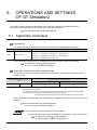
5.1
Applicable Controllers
5-1
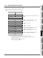
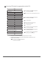
5.2
Operating Procedures
5-2
5.3
Setting Options
5-4
5.4
Opening Project
5-8
5.5
Precautions
5 - 10
5.6
Error Messages
5 - 11
6. OPERATIONS AND SETTINGS OF GT SoftGOT1000
6 - 1 to 6 - 10
6.1
Applicable Controllers
6-1
6.2
Operating Procedures
6-1
6.3
Opening Project
6-2
6.4
Functions
6-4
6.4.1
6.4.2
6.5
INDEX
A-6
4 - 1 to 4 - 44
Full screen mode .................................................................................................................. 6 - 4
Procedures for setting........................................................................................................... 6 - 7
Precautions
6 - 10
Index - 1 to Index - 1
MANUALS
The following table lists the manuals relevant to this product.
You can order the manuals as necessary.
MELSOFT
iQ Works
Refer to MELSOFT Navigator Help
GT Works2
Manual number
Manual name
(Model code)
GT Designer2 Version2 Basic Operation/Data Transfer Manual
Describes methods of the GOT1000 series installation operation, basic operation for drawing and transmitting data
SH-080529ENG
(1D7M24)
to GOT1000 series
(Sold
separately)*1
GT Designer2 Version2 Screen Design Manual (for GOT1000 Series) (1/3, 2/3, 3/3)
SH-080530ENG
Describes specifications and settings of the object functions used in GOT1000 series.
(Sold separately)*1
(1D7M25)
GOT1000 Series Connection Manual (1/3, 2/3, 3/3)
Describes system configurations of the connection method applicable to GOT1000 series and cable creation
(Sold separately)*1
GOT1000 Series Extended / Option Functions Manual
SH-080532ENG
(1D7M26)
SH-080544ENG
Describes extended functions and option functions applicable to GOT1000 series.
(Sold separately)*1
GT Simulator2 Version2 Operating Manual
(1D7M32)
SH-080546ENG
Describes the screen configuration, functions and using method of GT Simulator2 Version2.
(Sold separately)*1
GT SoftGOT1000 Version2 Operating Manual
(1D7M37)
SH-080602ENG
Describes the screen configuration, functions and using method of GT SoftGOT1000 Version2.
(Sold separately)*1
(1D7M48)
GOT1000 Series Gateway Functions Manual
SH-080545ENG
Describes specifications, system configurations and setting methods of the gateway functions.
(Sold separately)*1
(1D7M33)
GOT1000 Series MES Interface Function Manual
Describes the specifications, system configurations, and setting method of GT MES interface function.
(Sold separately)*1
SH-080654ENG
(1D7M63)
*1 The MELSOFT iQ Works product includes the PDF manual.
A-7
GX Works2
Manual number
Manual name
(Model code)
GX Works2 Beginner's Manual (Simple Project)
Explains fundamental operation methods such as creating, editing and monitoring programs in Simple project for
users inexperienced with GX Works2.
SH-080787ENG
(13JZ22)
(Sold separately)
GX Works2 Beginner's Manual (Structured Project)
Explains fundamental operation methods such as creating, editing and monitoring programs in Structured project
for users inexperienced with GX Works2.
SH-080788ENG
(13JZ23)
(Sold separately)
GX Works2 Version1 Operating Manual (Common)
Explains the system configuration of GX Works2 and the functions common to a Simple project and Structured
project such as parameter setting, the operating method for the online function.
SH-080779ENG
(13JU63)
(Sold separately)
GX Works2 Version1 Operating Manual (Simple Project)
Explains operation methods such as creating monitoring programs in Simple project of GX Works2.
(Sold separately)
GX Works2 Version1 Operating Manual (Structured Project)
Explains operation methods such as creating and monitoring programs in Structured project of GX Works2.
(Sold separately)
MT Developer2
Refer to MT Developer2 Help.
A-8
SH-080780ENG
(13JU64)
SH-080781ENG
(13JU65)
ABBREVIATIONS AND GENERIC TERMS
Abbreviations and generic terms used in this manual are as follows:
GOT
Abbreviation and generic term
Abbreviation of GT SoftGOT1000
GT1595
GT1595-X
Abbreviation of GT1595-XTBA, GT1595-XTBD
GT1585V-S
Abbreviation of GT1585V-STBA, GT1585V-STBD
GT1585-S
Abbreviation of GT1585-STBA, GT1585-STBD
GT1575V-S
Abbreviation of GT1575V-STBA, GT1575V-STBD
GT1575-S
Abbreviation of GT1575-STBA, GT1575-STBD
GT1575-V
Abbreviation of GT1575-VTBA, GT1575-VTBD
GT1575-VN
Abbreviation of GT1575-VNBA, GT1575-VNBD
GT1572-VN
Abbreviation of GT1572-VNBA, GT1572-VNBD
GT1565-V
Abbreviation of GT1565-VTBA, GT1565-VTBD
GT1562-VN
Abbreviation of GT1562-VNBA, GT1562-VNBD
GT1555-V
Abbreviation of GT1555-VTBD
GT1555-Q
Abbreviation of GT1555-QTBD, GT1555-QSBD
GT1550-Q
Abbreviation of GT1550-QLBD
GT1585
GT157
GT156
GOT1000 Series
Description
GT SoftGOT1000
GT155
GT15
GT115
, GT15
GT1155-Q
Abbreviation of GT1595, GT1585, GT157 , GT156 , GT155
Abbreviation of GT1155-QTBDQ, GT1155-QSBDQ, GT1155-QTBDA, GT1155-QSBDA,
GT1155-QTBD, GT1155-QSBD
GT1150-Q
Abbreviation of GT1150-QLBDQ, GT1150-QLBDA, GT1150-QLBD
Handy
GT1155HS-Q
Abbreviation of GT1155HS-QSBD
GOT
GT1150HS-Q
Abbreviation of GT1150HS-QLBD
GT11
, GT11
GT1030
Abbreviation of GT1030-LBD, GT1030-LBD2, GT1030-LBDW, GT1030-LBDW2
Abbreviation of GT1020-LBD, GT1020-LBD2, GT1020-LBL, GT1020-LBDW,
GT1020
GT10
Abbreviation of GT1155-Q, GT1150-Q, GT11 Handy GOT
GT1020-LBDW2, GT1020-LBLW
, GT10
Abbreviation of GT1030, GT1020
GOT900 Series
Abbreviation of GOT-A900 series, GOT-F900 series
GOT800 Series
Abbreviation of GOT-800 series
Software
Abbreviation and generic term
Description
GT Works2
SW D5C-GTWK2-J
GT Designer2
Abbreviation of screen drawing software GT Designer2 for GOT1000/GOT900 series
GT Converter2
Abbreviation of data conversion software GT Converter2 for GOT1000/GOT900 series
GT Simulator2
Abbreviation of screen simulator GT Simulator 2 for GOT1000/GOT900 series
GT SoftGOT1000
Abbreviation of monitoring software GT SoftGOT1000
MELSOFT iQ Works
Generic term for the iQ Platform compatible engineering environment products
MELSOFT Navigator
Generic product name of the integrated development environments for the SWnDNCIQWK
model (iQ Platform compatible engineering environment MELSOFT iQ Works) (n: version)
GX Works2
Generic product name for the SWnDNC-GXW2-E model (n: version)
MT Developer2
Generic product name for the SWnDNC-MTW2 model (n: version)
PX Developer
Abbreviation of SW D5C-FBDQ-E type FBD software package for process control
A-9
License key (for GT SoftGOT1000)
Abbreviation and generic term
License
Description
GT15-SGTKEY-U, GT15-SGTKEY-P
Others
Abbreviation and generic term
Description
GT Designer2 (Standalone)
Abbreviation of GT Designer2 started independently
GT Designer2 (Navigator)
Abbreviation of GT Designer2 started using MELSOFT Navigator
Windows
font
Intelligent function module
MODBUS
A - 10
/TCP
Abbreviation of TrueType font and OpenType font available for Windows
(Differs from the True Type fonts settable with GT Designer2)
Indicates the modules other than the programmable controller CPU, power supply module
and I/O module that are mounted to the base unit.
Generic term for the protocol designed to use MODBUS
network.
protocol messages on a TCP/IP
HOW TO USE THIS MANUAL
1 Functions
This manual describes functions available for the GT Designer2 Version2.77F.
2 Symbols
The following symbols are used in this manual.
Indicates the operation steps.
Brackets used for the menu and items differ.
[
] : Refers to an item displayed on the
computer screen or the GOT screen.
: Refers to a button displayed on the
computer screen or the GOT screen,
or a key of the computer keyboard.
Shows the items including detailed explanation
(manual, chapter, section, item of the manual).
Point
Refers to information required
for operation.
Refers to information useful
for operation.
Remark
Refers to supplementary
explanations.
* The above is different from the actual page, as it is provided for explanation only.
A - 11
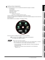
Shows functions applicable to
each GOT.
Each icon shows each GOT
model.
The colors of the icons show if the
functions are enabled or disabled
for each model.
Icon colors
Black: Enabled
Gray: Disabled
* The above is different from the actual page, as it is provided for explanation only.
A - 12
1
OVERVIEW
OVERVIEW
1.1 Overview
2
SPECIFICATIONS
This manual explains how to use GT Designer2, GT Simulator2, and GT SoftGOT1000 as MELSOFT iQ
Works and precautions.
This manual does not explain contents in common with using the software independently.
For how to use the software independently and precautions, refer to the following manuals.
For how to use GT Designer2 and precautions
GT Designer2 Version
Basic Operation/Data Transfer Manual
GT Designer2 Version
Screen Design Manual
3
Operating Manual
For how to use GT SoftGOT1000 and precautions
GT SoftGOT1000 Version
Operating Manual
4
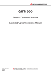
1 MELSOFT iQ Works
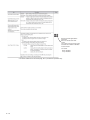
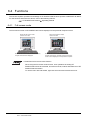
(1) Features of MELSOFT iQ Works
MELSOFT iQ Works is the product that integrates MITSUBISHI engineering tools (GX Works2, MT
Developer2, and GT Designer2) using the system management tool (MELSOFT Navigator).
With MELSOFT iQ Works, MELSOFT Navigator, which is the system management tool, controls
each engineering tool and manages all project data.
This improves interaction among the engineering tools and efficiency of system design.
MELSOFT iQ Works
MELSOFT Navigator
Controlling each engineering tool
Managing all project data for each engineering tool
6
MT Developer2
Programming software
5
OPERATIONS AND
SETTINGS OF GT
SoftGOT1000
Referring to labels
Calling motion
controller
programs
OPERATIONS AND
SETTINGS OF GT
Designer2
GT Simulator2 Version
PROJECT DATA
HANDLING
For how to use GT Simulator2 and precautions
OPERATIONS AND
SETTINGS OF GT
Simulator2
1.
Referring to labels
for motion controller
GT Designer2
GX Works2
Programming software
Drawing software
for programmable
for GOT
controller
INDEX
Referring to labels
For detailed features of MELSOFT iQ Works and MELSOFT Navigator, and how to use the
software, refer to the following.
iQ Works Beginner's Manual
1.1 Overview
1-1
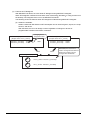
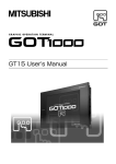
(2) Features of GT Designer2
With MELSOFT iQ Works, the user starts GT Designer2 using MELSOFT Navigator.
When GT Designer2 is started from the start menu of Microsoft Windows or using a shortcut on
the desktop, GT Designer2 does not run as MELSOFT iQ Works.
The following shows the features when GT Designer2 is started using MELSOFT Navigator.
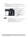
(a) Labels are available.
Labels created with GX Works2 or MT Developer2 can be used for figures, objects, the script
function, and others.
With the labels, the user can design screens regardless of changes in devices of
programmable controllers and motion controllers.
GX Works2 project
(Project name: Line A_control)
Changing device
assigned to label
Process 1_error lamp : X1000
Process 2_error lamp : X1001
:
X500
MT Developer2 project
(Project name: NC 1_control)
Process 1_error lamp : X2000
Process 2_error lamp : X2001
:
Label
Label
GT Designer2 project
Line A_control : Process 1_error lamp
NC 1_control : Process 1_error lamp
1-2
1.1 Overview
With labels, the user has no
need to change devices with GT
Works2 according to device
changes with GX Works2.
1
1.2 Software Package Configuration
OVERVIEW
This section explains GT Works2 software and data stored in the CD-ROMs.
1 CD-ROMs
MELSOFT iQ Works includes four CD-ROMs (Disk 1 to Disk 4).
GT Works2 software is stored in the CD-ROM Disk 4.
For how to use the CD-ROMs, refer to the following.
SPECIFICATIONS
2
1.4.1 Software installtion
2 GT Works2 software configuration
Software and data included in GT Works2 are the same as those in GT Works2 Version
For the software and the data in GT Works2 Version
.
3
, refer to the following.
PROJECT DATA
HANDLING
GT Designer2 Version Basic Operation/Data Transfer Manual
(1.2 Software Package Configuration)
1.3 Procedures Before Creating Project
4
Start
Reference manual
Install software other than
MELSOFT iQ Works as necessary.
・・・ iQ Works Installation Instructions
5
・・・ Chapter 1 in this manual
Start MELSOFT Navigator.
・・・ iQ Works Beginner's Manual
Chapter 3 in this manual Start GT Designer2 using
MELSOFT Navigator.
・・・iQ Works Beginner's Manual
Chapter 3 in this manual OPERATIONS AND
SETTINGS OF GT
Simulator2
Install MELSOFT iQ Works on
the personal computer.
6
・・・ GT Designer2 Version Basic Operation/Data Transfer Manual
GT Designer2 Version Screen Design Manual
Chapter 4 in this manual
OPERATIONS AND
SETTINGS OF GT
SoftGOT1000
Create project data.
OPERATIONS AND
SETTINGS OF GT
Designer2
The following shows the procedures before creating a project.
End
Procedures after creating project
For the procedures before operating the GOT, refer to the following.
1.2 Software Package Configuration
INDEX
GT Designer2 Version Basic Operation/Data Transfer Manual
(1.6 General Pre-operation Procedure)
1-3
1.4 Installation and Uninstallation
This section explains installation and uninstallation of each software.
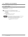
1.4.1
Software installtion
Some software can be installed when MELSOFT Navigator is installed, and some software requires to be
installed independently.
The following shows how to install the software.
1 Installing software when installing MELSOFT Navigator
The following software can be installed when MELSOFT Navigator is installed.
• GT Designer2
• GT Simulator2
• GT SoftGOT1000
For how to install the software, refer to the following.
iQ Works Installation Instructions
Remark
Installing GT Designer2, GT Simulator2, and GT SoftGOT1000 independently
The above software can also be installed independently.
Install the software from the CD-ROM (Disk 4) of MELSOFT iQ Works.
For how to install the software, refer to the following.
Installing software independently
1-4
1.4 Installation and Uninstallation
1.4.1 Software installtion
1
2 Installing software independently
The following software cannot be installed when MELSOFT Navigator is installed.
*1
OVERVIEW
GT SoftGOT2*1
GT Converter2
MES DB Connection Service
Document Converter
Data Transfer Tool
2
Software for GOT-A900 series
The software is not applicable to MELSOFT iQ Works.
3
PROJECT DATA
HANDLING
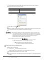
Install the software from the CD-ROM (Disk 4) of MELSOFT iQ Works.
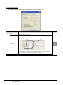
Inserting the CD-ROM into the CD-ROM drive of the personal computer displays the menu as shown in
the following figure.
Click a software icon to be installed, and install the software.
SPECIFICATIONS
•
•
•
•
•
OPERATIONS AND
SETTINGS OF GT
Designer2
4
OPERATIONS AND
SETTINGS OF GT
Simulator2
5
For the procedures for installing the software, refer to the following.
GT Designer2 Version Basic Operation/Data Transfer Manual
(2.2 Installing the Software Programs )
When menu screen does not appear
When the menu screen does not appear even if the CD-ROM (Disk 4) is inserted
into the CD-ROM drive, refer to either of the following methods.
INDEX
• Set Device Manager of Microsoft Windows so that the CD-ROM drive
automatically starts.
• Start Explorer, and double-click the following file in the CD-ROM drive.
GTWK2-J1.exe
OPERATIONS AND
SETTINGS OF GT
SoftGOT1000
6
1.4 Installation and Uninstallation
1.4.1 Software installtion
1-5
1.4.2
Software uninstallation
Some software can be uninstalled when MELSOFT Navigator is uninstalled, and some software requires to
be uninstalled independently.
The following shows how to uninstall the software.
1 Uninstalling software when uninstalling MELSOFT Navigator
The following software can be uninstalled when MELSOFT Navigator is uninstalled.
• GT Designer2
• GT Simulator2
• GT SoftGOT1000
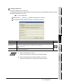
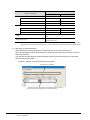
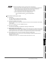
To uninstall MELSOFT Navigator, select [Add or Remove Programs] from the menu.
The following dialog box appears during uninstallation.
Check the boxes for the items to be uninstalled, and then click the Uninstall button to uninstall the
software with MELSOFT Navigator.
Remark
Uninstalling GT Designer2, GT Simulator2, and GT SoftGOT1000 independently
The above software can also be uninstalled independently.
For uninstalling the software independently, refer to the following.
GT Designer2 Version Basic Operation/Data Transfer Manual
(2.3 Uninstalling the Software Programs)
2 Uninstalling software independently
The following software cannot be uninstalled when MELSOFT Navigator is uninstalled.
•
•
•
•
•
GT SoftGOT2*1
GT Converter2
MES DB Connection Service
Document Converter
Data Transfer Tool
*1
Software for GOT-A900 series
The software is not applicable to MELSOFT iQ Works.
For how to uninstall the software, refer to the following.
GT Designer2 Version Basic Operation/Data Transfer Manual
(2.3 Uninstalling the Software Programs)
1-6
1.4 Installation and Uninstallation
1.4.2 Software uninstallation
1
OVERVIEW
SPECIFICATIONS
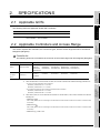
2.1 Applicable GOTs
2
SPECIFICATIONS
The following GOTs are applicable to MELSOFT iQ Works.
Applicable model
GT15,
GT SoftGOT1000,
*1
GT11*1,
GT10
The following GOTs are not applicable to MELSOFT iQ Works.
GT1155-QTBDA,
GT1150-QLBDA
3
2.2 Applicable Controllers and Access Range
This section explains the controllers, the connection types, and the access range that can be set with GT
Designer2 (Navigator).
PROJECT DATA
HANDLING
2.
4
1 Controller list
Model
Q02CPU,
QCPU (Q mode)
Q06HCPU,
Q12HCPU,
Q25HCPU,
Q06UDHCPU,
Q13UDHCPU,
Q02UCPU,
Q03UDCPU,
Q04UDHCPU,
Q26UDHCPU,
Q03UDECPU,
Q04UDEHCPU, Q06UDEHCPU, Q13UDEHCPU,
Q173CPU,
Q172HCPU,
5
Q26UDEHCPU
Motion
Q Series*2*3
CPU*1
Q172CPU,
Q173HCPU,
Q172DCPU,
Q173DCPU
*1
GT SoftGOT1000 cannot monitor motion controller CPUs.
*2
When the Q172CPU or the Q173CPU is used, use a motion controller CPU with the following production No.
• For bus connection and direct CPU connection
6
Q172CPU: production No.K *******or later
Q173CPU: production No.J *******or later
• For connections other than bus connection and direct CPU connection
Q172CPU: production No.N *******or later
Q173CPU: production No.M *******or later
*3
When SV13, SV22, or V43 is used with the Q172CPU or the Q173CPU, use a motion controller CPU with the
following OS.
• SW6RN-SV13Q
:
00H or later (00E or later for connecting to the Q172CPU or the Q173CPU via the bus connection or the direct CPU
connection)
• SW6RN-SV22Q
:
00H or later (00E or later for connecting to the Q172CPU or the Q173CPU via the bus connection or the direct CPU
connection)
• SW6RN-SV43
INDEX
controller
OPERATIONS AND
SETTINGS OF GT
SoftGOT1000
QCPU
Q02HCPU,
OPERATIONS AND
SETTINGS OF GT
Simulator2
Type
OPERATIONS AND
SETTINGS OF GT
Designer2
The following shows the controllers that can be set as the monitor target with GT Designer2 (Navigator).
: F00B or later
2.1 Applicable GOTs
2-1
Remark
Controllers that can be set with GT Designer2
Though controllers other than the above can be set with GT Designer2 (Navigator),
the functions dedicated to MELSOFT iQ Works are unavailable.
For controllers that can be set as the monitor target with GT Designer2 (Standalone), refer to the
following.
GT Designer2 Version Screen Design Manual
(2.7 Controller that can be Monitored and the Accessible Range)
2 Applicable controllers for each connection type
For controllers that can be monitored for each connection type, refer to the following.
GT Designer2 Version Screen Design Manual
(2.7 Controller that can be Monitored and the Accessible Range)
3 Access range
For the access range for monitoring, refer to the following.
GT Designer2 Version Screen Design Manual
(2.7 Controller that can be Monitored and the Accessible Range)
4 Precautions
(1) Controllers applicable to labels
Labels can be set for the following controllers only.
• Universal model QCPU
• High Performance model QCPU
• Q17nDCPU
To monitor controllers other than the above, set the device names for objects and others.
2-2
2.2 Applicable Controllers and Access Range
1
OVERVIEW
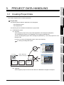
PROJECT DATA HANDLING
3.1 Creating Project Data
2
SPECIFICATIONS
This section explains how to create project data.
1 Project data
The following project data are applicable to GT Designer2.
• GT Designer2 project
• GT Designer2 file
3
The following shows the difference between the project data.
(1) GT Designer2 project
4
OPERATIONS AND
SETTINGS OF GT
Designer2
(a) Overview
A GT Designer2 project is the project data applicable to GT Designer2 (Navigator).
The GT Designer2 project is not applicable to GT Designer2 (Standalone).
To use a GT Designer2 project with GT Designer2 (Standalone), convert the project into a GT
Designer2 file.
PROJECT DATA
HANDLING
3.
For how to convert a GT Designer2 project, refer to the following.
3.4 Saving GT Designer2 Project
OPERATIONS AND
SETTINGS OF GT
Simulator2
5
Applicable
GT Designer2 (Navigator)
6
GX Works2
MT Developer2
GT Designer2
project
project
project
OPERATIONS AND
SETTINGS OF GT
SoftGOT1000
Data in MELSOFT
iQ Works workspace
Not applicable
GT Designer2 (Standalone)
3.1 Creating Project Data
INDEX
(b) Target file
A GT Designer2 project is stored as the data in the MELSOFT Navigator workspace.
3-1
Handling GT Designer2 project
To move, rename, or delete a GT Designer2 project, use MELSOFT Navigator.
MELSOFT Navigator manages the project name and the storage location for the
project.
When the project is moved, renamed, or deleted using the personal computer tools,
including Explorer, MELSOFT Navigator cannot recognize the project and the user
cannot open the project.
(2) GT Designer2 file (G1 file/GTE file)
A GT Designer2 file is the project data applicable to GT Designer2 (Standalone).
The GT Designer2 file is not applicable to GT Designer2 (Navigator).
To use a GT Designer2 file with GT Designer2 (Navigator), import the file to the MELSOFT
Navigator workspace.
For how to import a GT Designer2 file, refer to the following.
3.1.3 Importing GT Designer2 file
Not applicable
GT Designer2 (Navigator)
Applicable
GT Designer2 file
(GTE file)
GT Designer2 (Standalone)
(a) Target file
GT Designer2 processes data stored in either of the following formats as a GT Designer2 file.
• Project data in GT Designer2 Files format (*.GTE)
• Project data in GOT1000 Binary Files format (*.G1)
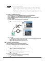
2 Creating GT Designer2 project
Create a GT Designer2 project using MELSOFT Navigator.
To create a GT Designer2 project, refer to the following methods.
(1) Creating new GT Designer2 project
For how to create a new GT Designer2 project, refer to the following.
3.1.1 Creating new GT Designer2 project
(2) Importing GT Designer2 project
For how to import a GT Designer2 project, refer to the following.
3.1.2 Importing GT Designer2 project
(3) Importing GT Designer2 file
For how to convert a GT Designer2 file, refer to the following.
3.1.3 Importing GT Designer2 file
3-2
3.1 Creating Project Data
1
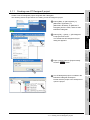
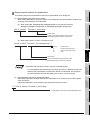
Creating new GT Designer2 project
1 Select [Start]
[All Programs]
[MELSOFT Application]
[MELSOFT iQ Works]
[MELSOFT
Navigator] from the menu, and then start
MELSOFT Navigator.
2
SPECIFICATIONS
1
OVERVIEW
Create a new GT Designer2 project using MELSOFT Navigator.
The following shows the procedures for creating a new GT Designer2 project.
2 Select [File]
[New]
[GT Designer2
Project] from the menu.
The Create New GT Designer2 Project
dialog box appears.
PROJECT DATA
HANDLING
3
2
OPERATIONS AND
SETTINGS OF GT
Designer2
4
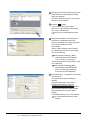
3 Input a project name for [Project Name].
Click the Create button.
OPERATIONS AND
SETTINGS OF GT
Simulator2
5
3
4 The GT Designer2 project is created in the
MELSOFT Navigator workspace.
Double-click the project in the workspace to
open the project.
INDEX
4
6
OPERATIONS AND
SETTINGS OF GT
SoftGOT1000
3.1.1
3.1 Creating Project Data
3.1.1 Creating new GT Designer2 project
3-3
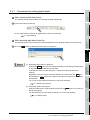
5 After opening the GT Designer2 project, the
Select Reference Project (Global Label)
dialog box appears.
Check the Selection boxes for the projects
with labels to be referred.
5
6 Click the OK button.
For the setting items in the Select
Reference Project (Global Label) dialog
box, refer to the following.
3.2 Opening GT Designer2 Project
6
7 When [Show Wizard on New Project] is
checked on the Operation tab in the
Preferences dialog box, selecting projects
to be referred starts the wizard
automatically.
Set the system settings with the wizard.
For operating procedures for the wizard,
refer to the following.
GT Designer2 Version Basic
Operation/Data Transfer Manual
(7.2.1 Creating a new project)
For the drawing environment settings, refer
to the following.
GT Designer2 Version Basic
Operation/Data Transfer Manual
(5.4.3 Customizing the drawing
environment of GT Designer2)
8
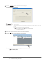
8 Select [Common]
[System Environment]
from the menu.
The System Environment dialog box
appears.
In [System Settings] of the System
Environment dialog box, click the
CH/Network Allocation(Label Setting) button,
and assign the channel number and the
network number to the project (label
setting).
For the label setting, refer to the following.
4.5 CH/Network Allocation (Label
Setting)
3-4
3.1 Creating Project Data
3.1.1 Creating new GT Designer2 project
1
When [Show Wizard on New Project] is not checked, the procedures after
as shown below.
are
OVERVIEW
Operation without wizard
2
GT Designer2 Version Basic
Operation/Data Transfer Manual
(7.2.1 Creating a new project)
3
and assign the channel number and the
network number to the project (label
setting).
For the label setting, refer to the following.
4.5 CH/Network Allocation (Label
Setting)
PROJECT DATA
HANDLING
CH/Network Allocation(Label Setting) button,
4
OPERATIONS AND
SETTINGS OF GT
Designer2
After setting the system settings, click the
SPECIFICATIONS
When [Show Wizard on New Project] is not
checked, the System Environment dialog
box appears.
Set the system settings in the dialog box.
For how to set the system settings, refer to
the following.
OPERATIONS AND
SETTINGS OF GT
Simulator2
5
INDEX
OPERATIONS AND
SETTINGS OF GT
SoftGOT1000
6
3.1 Creating Project Data
3.1.1 Creating new GT Designer2 project
3-5
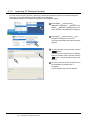
3.1.2
Importing GT Designer2 project
To create a GT Designer2 project by utilizing an existing GT Designer2 project from another workspace,
import the existing GT Designer2 project to MELSOFT Navigator.
The following shows the procedures for importing a GT Designer2 project.
1
1 Select [Start]
[All Programs]
[MELSOFT Application]
[MELSOFT iQ
Works]
[MELSOFT Navigator] from the
menu, and then start MELSOFT Navigator.
2 Select [File]
[Import Project]
[GT
Designer2 Project] from the menu.
The Import GT Designer2 Project dialog box
appears.
2
3
4
3-6
3.1 Creating Project Data
3.1.2 Importing GT Designer2 project
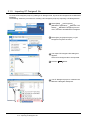
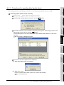
3 To specify the import source folder, click the
Browse button.
The Browse For Folder dialog box appears.
Select a reference folder, and then click the
OK button. The GT Designer2 project list
appears.
4 To select an import source workspace from
the workspace list, double-click a
workspace.
The GT Designer2 project list appears.
5 Click a GT Designer2 project to be imported
in the GT Designer2 project list.
The project name is displayed in [Project
Name].
OVERVIEW
1
2
6 Click the Open button.
SPECIFICATIONS
5
PROJECT DATA
HANDLING
3
6
4
OPERATIONS AND
SETTINGS OF GT
Designer2
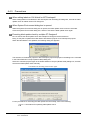
7 The GT Designer2 project is created in the
MELSOFT Navigator workspace.
OPERATIONS AND
SETTINGS OF GT
Simulator2
5
INDEX
OPERATIONS AND
SETTINGS OF GT
SoftGOT1000
6
3.1 Creating Project Data
3.1.2 Importing GT Designer2 project
3-7
3.1.3
Importing GT Designer2 file
To create a GT Designer2 project by utilizing a GT Designer2 file, import the GT Designer2 file to MELSOFT
Navigator.
The following shows the procedures for creating a GT Designer2 project by importing a GT Designer2 file.
1
1 Select [Start]
[All Programs]
[MELSOFT Application]
[MELSOFT iQ
Works]
MELSOFT Navigator] from the
menu, and then start MELSOFT Navigator.
2 Select [File]
[Import Project]
Designer2 File] from the menu.
[GT
2
3 The Import GT Designer2 File dialog box
appears.
Select a GT Designer2 file to be imported.
4 Click the Open button.
3
4
5 The GT Designer2 project is created in the
MELSOFT Navigator workspace.
3-8
3.1 Creating Project Data
3.1.3 Importing GT Designer2 file
1
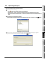
3.2 Opening GT Designer2 Project
1 Select [Start]
[All Programs]
[MELSOFT Application]
[MELSOFT iQ
Works]
[MELSOFT Navigator] from the
menu, and then start MELSOFT Navigator.
2
2 Right-click a GT Designer2 project to be
opened.
3
PROJECT DATA
HANDLING
3 Select [Open Project] from the menu.
SPECIFICATIONS
1
OVERVIEW
Open a GT Designer2 project using MELSOFT Navigator.
The following shows the procedures for opening a GT Designer2 project.
2
OPERATIONS AND
SETTINGS OF GT
Designer2
4
3
OPERATIONS AND
SETTINGS OF GT
SoftGOT1000
6
INDEX
5 The Select Reference Project (Global
Label) dialog box*1 appears.
Check the Selection boxes for the projects
with labels to be referred, and then click the
OK button.
OPERATIONS AND
SETTINGS OF GT
Simulator2
5
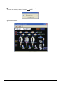
4 When security is set for the GT Designer2
project, the User Authentication dialog box
appears.
Input the user name and the password, and
then click the OK button.
For the security setting, refer to the
following.
4.2 Security Setting
3.2 Opening GT Designer2 Project
3-9
6 The dialog box shown in the left appears.
Check the message, and then click the
OK button.
The label update check automatically starts.
For the label update check, refer to the
following.
4.4 Label Update Check
*1 Select Reference Project (Global Label) dialog box
The following shows the setting items in the Select Reference Project (Global Label) dialog box.
Item
Selection
3 - 10
Description
Check boxes for GX Works2 projects or MT Developer2 projects with labels to be referred by GT
Designer2.
Project Name
Displays names for GX Works2 projects or MT Developer2 projects.
PC/CPU Type
Displays programmable controller CPU types for GX Works2 projects or MT Developer2 projects.
Title
Displays titles for GX Works2 projects or MT Developer2 projects.
Select All
Click the item to check all the Selection boxes.
Deselect
Click the item to uncheck all the Selection boxes.
Undo
Click the item to return the settings for [Selection] to those when the dialog box is displayed.
OK
Click the item to set the settings and to open the GT Designer2 project.
3.2 Opening GT Designer2 Project
Model
Labels set for objects and others are converted into device names.
To close the project, exit GT Designer2 by clicking the × button.
The following shows the procedures for closing a GT Designer2 project.
1 Click the × button on the right side of the
title bar.
1
2 When the GT Designer2 project has any
changes, the dialog box shown in the left
appears.
• To exit GT Designer2 with overwriting the
project, click the Yes button.
• To exit GT Designer2 without saving the
project, click the No button.
• To continue drawing, click the Cancel
button.
• To save the project as a new file, click the
Save As New button.
SPECIFICATIONS
3
PROJECT DATA
HANDLING
*1
(2) Selecting [Close] from menu
With GT Designer2 (Navigator), the user cannot close a GT Designer2 project by
selecting [Project]
[Close] from the menu.
4
OPERATIONS AND
SETTINGS OF GT
Designer2
• Label setting*1
• CH/network allocation (label setting)
• Security setting
2
5
OPERATIONS AND
SETTINGS OF GT
Simulator2
For saving a GT Designer2 project, clicking the Save As New button converts the
GT Designer2 project into a GT Designer2 file and saves the file.
When the GT Designer2 project is saved as a GT Designer2 file, the following
settings are deleted.
6
OPERATIONS AND
SETTINGS OF GT
SoftGOT1000
(1) Saving as new file
OVERVIEW
1
3.3 Closing GT Designer2 Project
INDEX
3 Clicking the Save As New button displays
the Save As dialog box.
Input a name of the GT Designer2 file, and
then click the Save button.
3.3 Closing GT Designer2 Project
3 - 11
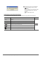
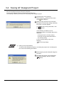
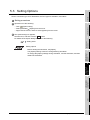
3.4 Saving GT Designer2 Project
Save a GT Designer2 project using GT Designer2.
To save a GT Designer2 project, overwriting is available only.
The following shows the procedures for overwriting a GT Desiger2 project.
1 Operate either of the following.
Select [Project]
[Save] from the menu.
Click
(Save Project).
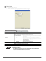
2 When the login user does not have write
permission in the security setting, the dialog
box shown in the left appears.
3 To overwrite the security information, click
the Yes button.
In the following conditions, the GT
Designer2 project is overwritten without the
dialog box.
• The project has no security setting.
• The login user has write permission in
the security setting.
4 For the security setting, refer to the
following.
5
4.2 Security Setting
(1) Saving as new file (GTE file)
To save the GT Designer2 project by converting the project into a GT Desgner2
file, refer to the following procedures.
1 Select [Project]
the menu.
[Save As(GTE File)] from
2 The dialog box shown in the left appears.
Check the message, and then click the
Yes button.
3 - 12
3.4 Saving GT Designer2 Project
1
4 Select a storage folder for the file, and then
input a file name for [File name].
OVERVIEW
3 The Save As dialog box appears.
SPECIFICATIONS
2
• Label setting*1
• CH/network allocation (label setting)
• Security setting
4
OPERATIONS AND
SETTINGS OF GT
Designer2
Labels set for objects and others are converted into device names.
OPERATIONS AND
SETTINGS OF GT
Simulator2
5
OPERATIONS AND
SETTINGS OF GT
SoftGOT1000
6
INDEX
*1
3
PROJECT DATA
HANDLING
(2) Precautions for saving as new file (GTE file)
For saving a GT Designer2 project, selecting [Save As(GTE File)] converts the GT
Designer2 project into a GT Designer2 file and saves the file.
When the GT Designer2 project is saved as a GT Designer2 file, the following
settings are deleted.
3.4 Saving GT Designer2 Project
3 - 13
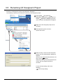
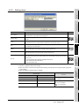
3.5 Renaming GT Designer2 Project
Rename a GT Designer2 project using MELSOFT Navigator.
The following shows the procedures for renaming a GT Designer2 project.
1
1 Select [Start]
[All Programs]
[MELSOFT Application]
[MELSOFT iQ
Works]
[MELSOFT Navigator] from the
menu, and then start MELSOFT Navigator.
2 Right-click a GT Designer2 project to be
renamed.
3 Select [Rename] from the menu.
Input a new name.
2
3
4 When security is set for the GT Designer2
project, the User Authentication dialog box
appears.
5 Input the user name and the password, and
then click the OK button.
6 When the user name and the password are
correct, the GT Designer2 project is
renamed.
7
8 For the security setting, refer to the
following.
9
3 - 14
3.5 Renaming GT Designer2 Project
4.2 Security Setting
1
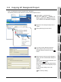
3.6 Copying GT Designer2 Project
1 Select [Start]
[All Programs]
[MELSOFT Application]
[MELSOFT iQ
Works]
[MELSOFT Navigator] from the
menu, and then start MELSOFT Navigator.
2
2 Right-click a GT Designer2 project to be
copied.
3
PROJECT DATA
HANDLING
3 Select [Add Copy] from the menu.
SPECIFICATIONS
1
OVERVIEW
Copy a GT Designer2 project using MELSOFT Navigator.
The following shows the procedures for copying a GT Designer2 project.
4
OPERATIONS AND
SETTINGS OF GT
Designer2
2
3
6 Input the user name and the password, and
then click the OK button.
When the user name and the password are
correct, a copy of the GT Designer2 project
is created.
For the security setting, refer to the
following.
7
4.2 Security Setting
3.6 Copying GT Designer2 Project
3 - 15
OPERATIONS AND
SETTINGS OF GT
SoftGOT1000
5 When security is set for the GT Designer2
project, the User Authentication dialog box
appears.
6
INDEX
4 The Copy Project dialog box appears.
Input a project name for the new GT
Designer2 project, and then click the OK
button.
OPERATIONS AND
SETTINGS OF GT
Simulator2
5
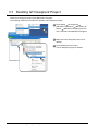
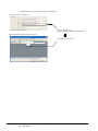
3.7 Deleting GT Designer2 Project
Delete a GT Designer2 project using MELSOFT Navigator.
The following shows the procedures for deleting a GT Designer2 project.
1
1 Select [Start]
[All Programs]
[MELSOFT Application]
[MELSOFT iQ
Works]
[MELSOFT Navigator] from the
menu, and then start MELSOFT Navigator.
2 Right-click a GT Designer2 project to be
deleted.
3 Select [Delete] from the menu.
The GT Designer2 project is deleted.
2
3
3 - 16
3.7 Deleting GT Designer2 Project
1
OVERVIEW
3.8 Precautions
1 Precautions for GT Designer2
(1) Handling project data
With GT Designer2 (Navigator), the following operations are unavailable.
• Creating a new GT Designer2 project
• Importing a GT Designer2 project
• Importing a GT Designer2 file
• Opening a GT Designer2 project
SPECIFICATIONS
Closing a GT Designer2 project*1
Renaming a GT Designer2 project
Copying a GT Designer2 project
Deleting a GT Designer2 project
3
*1
PROJECT DATA
HANDLING
Execute the above operations using MELSOFT Navigator.
Closing a GT Designer2 project is unavailable using MELSOFT Navigator.
To close a GT Designer2 project, exit GT Designer2 by clicking the × button.
For how to exit GT Designer2, refer to the following.
4
3.3 Closing GT Designer2 Project
(2) Interrupting new project wizard
For creating a new GT Designer2 project, when the new project wizard is interrupted by clicking the
Close button or Cancel
button, exit GT Designer2 by clicking the × button.
Failure to do so does not create a GT Designer2 project.
To create a new GT Designer2 project again, use MELSOFT Navigator.
OPERATIONS AND
SETTINGS OF GT
Designer2
•
•
•
•
2
5
6
OPERATIONS AND
SETTINGS OF GT
SoftGOT1000
(1) Saving GT Designer2 project as another name
Saving a GT Designer2 project as another name is unavailable.
Overwriting a GT Designer2 project is available only.
For utilizing an existing GT Designer2 project to create another GT Designer2 project, refer to either
of the following methods.
• Importing a GT Designer2 project using MELSOFT Navigator
OPERATIONS AND
SETTINGS OF GT
Simulator2
2 Precautions for saving GT Designer2 project
3.1.2 Importing GT Designer2 project
• Copying a GT Designer2 project in the MELSOFT Navigator workspace
3.6 Copying GT Designer2 Project
(2) Exporting GT Designer2 project
For saving a GT Designer2 project, selecting [Save As(GTE File)] converts the GT Designer2
project into a GT Designer2 file and saves the file.
When the GT Designer2 project is saved as a GT Designer2 file, the following settings are deleted.
*1
INDEX
• Label setting*1
• CH/network allocation (label setting)
• Security setting
Labels set for objects and others are converted into device names.
3.8 Precautions
3 - 17
4.
OPERATIONS AND SETTINGS OF
GT Designer2
This chapter explains operations and settings specific to GT Designer2 (Navigator).
For how to use GT Designer2 other than the above, refer to the following.
GT Designer2 Version
Basic Operation/Data Transfer Manual
GT Designer2 Version
Screen Design Manual
4.1 Drawing Environment
The drawing environment settings differ between GT Designer2 (Navigator) and GT Designer2 (Standalone).
The following shows the settings with GT Designer2 (Navigator).
(1) Settings on Operation tab
The settings on the Operation tab in the Preferences dialog box of GT Designer2 (Navigator) differ
from those of GT Designer2 (Standalone).
(a) Unavailable setting items
With GT Designer2 (Navigator), the following setting items cannot be set.
• Auto File Save
• Show "Select Project" dialog when you start GT Designer2
(b) Setting items with different contents
With GT Designer2 (Navigator), the contents of the following setting item differ from those with
GT Designer2 (Standalone).
• Open "Slect CH No." dialog
For the setting items on the Operation tab, refer to the following.
Setting items
(1) Auto file save
With GT Designer2 (Navigator), files cannot be saved automatically.
Save GT Designer2 projects frequently.
(2) Select Project dialog box
The Select Project dialog box does not appear when GT Desiger2 (Navigator)
starts.
The GT Designer2 project that is selected with MELSOFT Navigator opens.
1 How to set drawing environment
The following shows the procedures for setting the drawing environment.
1 Select [Project]
[Preferences] from the menu.
2 The Preferences dialog box appears.
Set the environment of the drawing screen on the Operation tab and the View tab.
4-1
4.1 Drawing Environment
1
2 Setting items
OVERVIEW
(1) Toolbars tab, Icon tab, and View tab
For the setting items on the Toolbars tab and the Icon tab, refer to the following.
GT Designer2 Version Basic Operation/Data Transfer Manual
(5.4.2 Customizing the toolbars)
2
For the setting items on the View tab, refer to the following.
SPECIFICATIONS
GT Designer2 Version Basic Operation/Data Transfer Manual
(5.4.3 Customizing the drawing environment of GT Designer2)
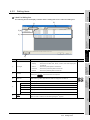
(2) Operation tab
The following shows the setting items on the Operation tab.
PROJECT DATA
HANDLING
3
OPERATIONS AND
SETTINGS OF GT
Designer2
4
Item
Description
placement
: After arranging objects, the selected status (status with handle) is
OPERATIONS AND
SETTINGS OF GT
Simulator2
Checked
Deselect Figure/Object after its
5
Model
canceled.
Not checked : With the selected status (status with handle), figures or objects are
arranged on the drawing screen.
Checked
Release the selective state of
tools
: After setting figures or objects, the tool selected status is canceled. It is
6
convenient to arrange different figures or objects.
Not checked : After setting figures or objects, the selected status remains active. It is
Checked
System setting on new
OPERATIONS AND
SETTINGS OF GT
SoftGOT1000
convenient to arrange the same figures or objects continuously.
: The system settings dialog box (GOT type, controller type, and others)
appears in creation of a new project.
Not checked : The system settings dialog box (GOT type, controller type, and others)
does not appear in creation of a new project.
Checked
automatically appears.
Not checked : After arranging an object on the drawing screen, the setting dialog box
does not automatically appear.
(To the next page)
INDEX
Change object after create
: After arranging an object on the drawing screen, the setting dialog box
4.1 Drawing Environment
4-2
Item
Show Wizard on New Project
Description
Checked
Checked
move to temporary area.)
: A figure or object can be moved on the screen display area by a drag
operation. A figure or object can be moved to the temporary area by a
Figure/Object move on screen
display area (with ALT key,
: When creating a new project, the wizard screen appears.
Not checked : When creating a new project, the wizard screen does not appear.
drag operation with holding down the ALT key.
Not checked : A figure or object can be moved to the temporary area by a drag
operation. A figure or object can be moved on the screen display area by
a drag operation with holding down the ALT key.
Close an edited screen when
opening another if the number
of open screens is at its
Set the maximum number of screens (1 to 25 screens).
maximum
The set value is enabled at the next startup.
(Effective from the next startup
of GT Designer2)
Set whether to display or hide the Select CH No. dialog box when a device is set.
Select one of the following items.
• Only New Device:
The Select CH No. dialog box appears only when a new device is set.
The dialog box does not appear when a set device is changed.
• Open:
The Select CH No. dialog box appears every time a device is set.
• Not Open (Selected "Device Setting" dialog will be opened):
The operation differs according to the setting for [Label/CH No.].
Open "Select CH No." dialog
[1] to [4]
:Displays the device setting dialog box for the selected
[Latest]
:Displays the device setting dialog box that is previously
channel No.
displayed. The channel No. is the same as that for the dialog
box previously displayed.
[Label]
:Displays the Label List dialog box.
Regardless of the above settings, by holding down the Shift key and clicking the
Dev
4-3
button, the Select CH No. dialog box appears.
4.1 Drawing Environment
Model
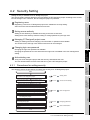
Setting security is available for a GT Designer2 project.
The security setting restricts displaying and overwriting the GT Designer2 project according to the access
level of the login user. Therefore, the GT Designer2 project is protected.
1 Registering users
OVERVIEW
1
4.2 Security Setting
2
SPECIFICATIONS
Registering a user as a GT Designer2 project user enables the security setting.
Add a new user with the Administrators access level.
2 Setting access authority
Setting access authority is available according to the user access level.
Setting the access authority restricts reading or writing operations by the login user.
3
3 Managing GT Designer2 project users
PROJECT DATA
HANDLING
Adding or deleting users and changing user information or password are available.
The access level of the login user restricts users that can be managed.
4 Changing login user password
4
OPERATIONS AND
SETTINGS OF GT
Designer2
Changing the login user password is available.
Changing the passwords for users other than the login user is available in the user management
setting.
5 Authenticating user
To log into a GT Designer2 project with the security, authenticate the user.
The user authentication restricts users that can log into a GT Designer2 project.
5
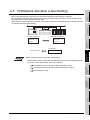
Procedures for setting security
OPERATIONS AND
SETTINGS OF GT
Simulator2
4.2.1
The following shows the procedures for setting the security for a GT Designer2 project.
Start
4.2.2
Adding users
Set the access privilege for the GT Designer2 project.
4.2.2
Access control setting
4.2.2
User management
Change the password of the login user for the
GT Designer2 project.
4.2.2
Changing password
Execute the user authentication for the GT Designer2
project.
4.2.2
User authentication
6
OPERATIONS AND
SETTINGS OF GT
SoftGOT1000
Register a user with the Administrators access
level with a GT Designer2 project.
Manage users for the GT Designer2 project.
Add a user for the GT Designer2 project.
Delete a user for the GT Designer2 project.
INDEX
Change the password of a user for the
GT Designer2 project.
End
4.2 Security Setting
4.2.1 Procedures for setting security
4-4
4.2.2
Setting items
1 Adding users
When no user with the Administrators access level is registered with a GT Designer2 project, security
cannot be set for the project.
To set the security for the project, add a user with the Administrators access level by selecting
[Project]
[Security]
[User Management] from the menu.
User management
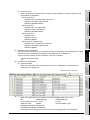
2 Access control setting
Set the access authority for a GT Designer2 project according to each access level.
1 Select [Project]
[Security]
[Data Security Setting] from the menu.
2 The Access Control Setting dialog box appears. Set the access authority.
3
Item
Description
Access Target
Displays the target GT Designer2 project for the access control.
Set the access authority of [Read] and [Write] for each access level.
•Read
Access
Authority*1
•Write
: Restricts displaying the GT Designer2 project.
: Restricts overwriting the GT Designer2 project.
For setting the access levels, refer to the following.
User management
For details of *1, refer to the next page.
4-5
4.2 Security Setting
4.2.2 Setting items
Model
1
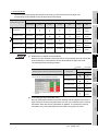
*1 Access Authority
Users
Developers(Level2)
Not settable
Not settable
Not settable
Not settable
Not settable
Developers(Level1)
Not settable
Not settable
Not settable
Not settable
Users
Not settable
Not settable
Not settable
Not settable
Not settable
Read
Write
Permit
Permit
(Fixed)
(Fixed)
Permit/
Permit/
Protect
Protect
Permit/
Permit/
Protect
Protect
Permit/
Permit/
Protect
Protect
Permit/
Protect
Protect
(Fixed)
(1) Restrictions on settable access authority
When the access authority of the login user is set to [Permit], the user can set the
access authority of users with the access levels below the login user level.
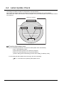
The following shows a setting example.
: Settable
Setting example of access level and access authority
Example) Login user access level: Developers(Level2)
Access authority: Read permitted/write prohibited
Access level
Administrators
: Not settable
Access authority
Read
Write
(Fixed)
(Fixed)
Developers(Level3)
Developers(Level2)
*1
*1
Developers(Level1)
*1
The login user cannot change the user's access
authority.
Users
(Fixed)
2
SPECIFICATIONS
(Level1)
3
PROJECT DATA
HANDLING
(Level2)
4
OPERATIONS AND
SETTINGS OF GT
Designer2
(Level3)
5
OPERATIONS AND
SETTINGS OF GT
Simulator2
Developers
Administrators
Developers(Level3)
L
o
w
Developers
6
(2) Overwriting (security information only)
Security information includes the access authority and the password. Even if the
login user does not have write permission, the user can overwrite only the security
information when the security information is updated. To overwrite the security
information only, select [Save(Security information only)] from the menu.
INDEX
H
i
g
h
Administrators
Access authority
Developers
OPERATIONS AND
SETTINGS OF GT
SoftGOT1000
Access authority setting
Access level (Login user)
OVERVIEW
The access authority setting has restrictions according to the access level of the login user.
The following shows settable access levels and access authority.
4.2 Security Setting
4.2.2 Setting items
4-6
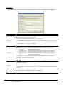
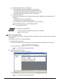
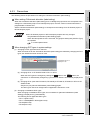
3 User management
Adding or deleting users and changing user information or password are available.
1 Select [Project]
[Security]
[User Management] from the menu.
2 Operate either of the following.
• For GT Designer2 projects without security
The Add User dialog box appears. Add a user with the Administrators access level.
(
*2 Adding user)
• For GT Designer2 projects with security
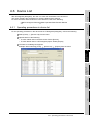
The User Management dialog box appears. Set the user management.
Item
Description
User List for this
project (Project Name)
Displays the target GT Designer2 project name of the user management.
Displays the numbers of registered users and registerable users.
Registration
Up to 128 users can be registered.
User Name
Displays the user names registered with the GT Designer2 project.
Access Level
Displays the access levels set for the users.
Add a user.
Add *1*2
Clicking the Add button displays the Add User dialog box. Add a user.
Delete a registered user.
Delete *1*3
Select a user to be deleted from the list, and click the Delete button.
Change the information of a user.
Change *1*4
Select a user with the information to be changed, and click the Change button. The Change User
Information dialog box appears, and change the user information.
Change the password for a user.
Password Setup *1*5
Select a user with the password to be changed from the list, and click the Password Setup button. The
Password Change dialog box appears, and change the password.
4-7
4.2 Security Setting
4.2.2 Setting items
Model
1
*1 Restrictions
Access level (Login user)
OVERVIEW
The user management setting has restrictions according to the access level of the login user.
The following shows the settable user management setting according to each access level.
User management setting
Administrators
Developers(Level3)
Developers(Level2)
Developers(Level1)
Users
2
Developers(Level3)
Not settable
Not settable
Developers(Level2)
Not settable
Not settable
Not settable
Developers(Level1)
Not settable
Not settable
Not settable
Not settable
Users
Not settable
Not settable
Not settable
Not settable
SPECIFICATIONS
Administrators
Not settable
PROJECT DATA
HANDLING
3
OPERATIONS AND
SETTINGS OF GT
Designer2
4
OPERATIONS AND
SETTINGS OF GT
Simulator2
5
INDEX
OPERATIONS AND
SETTINGS OF GT
SoftGOT1000
6
4.2 Security Setting
4.2.2 Setting items
4-8
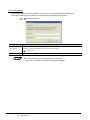
*2 Adding user
Set the user name, the access level, and the password for a user to be added to the GT Designer2
project.
Item
Description
Set the name of a user to be added to the GT Designer2 project.
The user name must include 1 to 20 one-byte characters.
(No two-byte or one-byte space can be input at the end of the user name.)
User Name
The following shows characters applicable to the user name. (Uppercase and lowercase characters are recognized,
respectively.)
(space)!"#$%&()*+,-./:;<=>?@[\]^_`{|}~0123456789
AaBbCcDdEeFfGgHhIiJjKkLlMmNnOoPpQqRrSsTtUuVvWwXxYyZz
Set the access level for the user added to the GT Designer2 project.
(To add a user to the GT Designer2 project with no registered user, [Administrators] can be selected only.)
Access Level
•Administrators
: All the functions are available.
•Developers(Level3)
: The security setting, access to data, and certain oparations are restricted.
•Developers(Level2)
: The security setting, access to data, and certain oparations are restricted.
•Developers(Level1)
: The security setting, access to data, and certain oparations are restricted.
•Users
: Browsing data is available only.
The Develpers(Level1), Develpers(Level2), and Develpers(Level3) have the same default access authority.
Changing the access authority is available in the access control setting.
For the access control setting, refer to the following.
Access control setting
Set the password for authenticating the user when the GT Designer2 is opened.
(The password is displayed as *.)
The password must include 6 to 32 one-byte characters.
Password
The following shows characters applicable to the password. (Uppercase and lowercase characters are recognized,
respectively.)
(space)!"#$%&'()*+,-./:;<=>?@[\]^_`{|}~0123456789
AaBbCcDdEeFfGgHhIiJjKkLlMmNnOoPpQqRrSsTtUuVvWwXxYyZz
Reenter Password
4-9
Check consistency between [Password] and [Reenter Password]. (The password is displayed as *.)
4.2 Security Setting
4.2.2 Setting items
1
*3 Deleting user
Delete a user selected from the user list in the User Management dialog box.
button to
OVERVIEW
The following message appears. Click the Yes button to delete the user, or click the No
keep the user.
SPECIFICATIONS
2
To set the security for a GT Designer2 project, a user with the Administrators access
level must be registered.
Deleting all the users registered with the GT Designer2 project disables the user
authentication function and the access control function. As a result, the security
setting for the GT Designer2 project is canceled.
3
PROJECT DATA
HANDLING
When deleting all registered users
OPERATIONS AND
SETTINGS OF GT
Designer2
4
*4 Changing user information
5
OPERATIONS AND
SETTINGS OF GT
Simulator2
Change the user name and the access level of a user selected from the user list in the User Management
dialog box.
OPERATIONS AND
SETTINGS OF GT
SoftGOT1000
6
Item
Description
Set a new user name.
User Name
For details of characters applicable to the user name, refer to the following.
INDEX
*2 Adding user
Set a new access level.
Access Level
The access level must be below the access level of the login user.
For details of the access levels, refer to the following.
*2 Adding user
4.2 Security Setting
4.2.2 Setting items
4 - 10
*5 Changing password
Change the password of a user selected from the user list in the User Management dialog box.
To change the password of the login user, select [Password Change] from the menu.
Changing password
Item
Description
Set a new password. (The password is displayed as *.)
New Password
For details of characters applicable to the password, refer to the following.
*2 Adding user
Reenter Password
Check consistency between [New Password] and [Reenter Password]. (The password is displayed as *.)
When new password and reenter password do not match
Check the new password, and then set the password again.
4 - 11
4.2 Security Setting
4.2.2 Setting items
1
Change the password of the login user.
To change the password of a user selected from the user list in the User Management dialog box, select
[Password Change] from the menu.
User management
[Security]
2
[Password Change] from the menu.
SPECIFICATIONS
1 Select [Project]
OVERVIEW
4 Changing password
2 The Password Change dialog box appears. Change the password.
PROJECT DATA
HANDLING
3
Item
Old Password
Description
Model
Set the old password. (The password is displayed as *.)
5
Set a new password. (The password is displayed as *.)
For details of characters applicable to the password, refer to the following.
OPERATIONS AND
SETTINGS OF GT
Simulator2
New Password
*2 Adding user
Check consistency between [New Password] and [Confirm Password].
(The password is displayed as *.)
6
OPERATIONS AND
SETTINGS OF GT
SoftGOT1000
(1) When old password is incorrect
Check the old password, and then set the password again.
(2) When new password and confirm password do not match
Check the new password, and then set the password again.
INDEX
Confirm Password
OPERATIONS AND
SETTINGS OF GT
Designer2
4
4.2 Security Setting
4.2.2 Setting items
4 - 12
5 User authentication
To log into a GT Designer2 project with the security, authenticate the user.
1 Open a GT Designer2 with the security.
(
3.2 Opening GT Designer2 Project)
2 The User Authentication dialog box appears. Execute the user authentication.
3
Item
Description
User Name
Set the user name to be authenticated.
Password
Set the password of the user to be authenticated. (The password is displayed as *.)
When user is not authenticated
(1) When login user does not have read permission
Because the login user is prohibited to read the GT Designer2 project with the
security, the user cannot open the project.
Log into the GT Designer2 project as a user with read permission to open the
project.
(2) When user authentication fails
The user name or the password is incorrect.
Check the user name and the password, and then execute the user authentication
again.
4 - 13
4.2 Security Setting
4.2.2 Setting items
1
Precautions
1 When user forgets user name and password
2
SPECIFICATIONS
When the user forgets the user name and the password, the user cannot open the corresponding GT
Designer2 project with the security.
Delete the GT Designer2 project, and then create a new GT Designer2 project.
OVERVIEW
4.2.3
PROJECT DATA
HANDLING
3
OPERATIONS AND
SETTINGS OF GT
Designer2
4
OPERATIONS AND
SETTINGS OF GT
Simulator2
5
INDEX
OPERATIONS AND
SETTINGS OF GT
SoftGOT1000
6
4.2 Security Setting
4.2.3 Precautions
4 - 14
4.3 Label Setting
A label is a character string used as a device set in a GX Works2 project or MT Developer2 project.
For a GT Designer2 project, the label can be used instead of a device name in the device setting.
GX Works2 project
(Project name: Line A_control)
Changing device
assigned to label
Process 1_error lamp : X1000
Process 2_error lamp : X1001
:
X500
MT Developer2 project
(Project name: NC 1_control)
Process 1_error lamp : X2000
Process 2_error lamp : X2001
:
Label
Label
GT Designer2 project
With labels, the user has no
need to change devices with GT
Works2 according to device
changes with GX Works2.
Line A_control : Process 1_error lamp
NC 1_control : Process 1_error lamp
Labels are created with GX Works2 or MT Developer2.
For how to create labels, refer to the following.
GX Works2 Version1 Operating Manual (Simple Project)
GX Works2 Version1 Operating Manual (Structured Project)
MT Developer2 Help
1 Applicable labels on GT Designer2
Only global labels are applicable to GT Designer2.
The following shows conditions for using global labels on GT Designer2.
(1) Conditions for GT Designer2
(a) Selecting reference project
When starting GT Designer2, label data of the GX Works2 project and MT Developer2 project
selected in the Select Reference Project (Global Label) dialog box can be used.
For the Select Reference Project (Global Label) dialog box, refer to the following.
3.2 Opening GT Designer2 Project
4 - 15
4.3 Label Setting
(2) Conditions for MT Developer2
When [Set system variables] is not checked in the auto device setting on MT Developer2, the label
data with the devices automatically assigned are inapplicable to GT Designer2.
For the auto device setting for MT Developer2, refer to the following.
MT Developer2 Help
(3) Conditions for global labels
OVERVIEW
1
SPECIFICATIONS
2
PROJECT DATA
HANDLING
3
4
OPERATIONS AND
SETTINGS OF GT
Designer2
(b) Controller types
When the following controller types are set for [System Settings] on [System Environment],
global labels are applicable.
• When using GT15
MELSEC-QnU, Q17nD/NC/DR, CRnD-700
MELSEC-QnA/Q/QS, MELDAS C6
MELSEC-Q(Multi)/Q-Motion
• When using GT11
MELSEC-QnU, Q17nD/NC/DR
MELSEC-QnA/Q, MELDAS C6
MELSEC-Q(Multi)/Q-Motion
• When using GT10
MELSEC-QnU
MELSEC-QnA/Q
MELSEC-Q(Multi)
• When using GT SoftGOT1000
MELSEC-QnU, Q17nNC/DR, CRnD700
MELSEC-QnA/Q/QS, MELDAS C6
MELSEC-Q(Multi)
5
OPERATIONS AND
SETTINGS OF GT
Simulator2
(a) Applicable labels
When the class, label name, and data type are set for a global label, the label data are
applicable to GT Designer2.
Class, label name, data type
OPERATIONS AND
SETTINGS OF GT
SoftGOT1000
6
4.3 Label Setting
INDEX
When using label data for GT Designer2, the following data types can be used.
BIT,
WORD[signed],
DWORD[signed],
FLOAT (Single Precision), Timer,
Counter,
Retentive Timer,
ARRAY,
Structured Data Types.
WORD[unsigned]/BIT String[16-bit],
DWORD[unsigned]/BIT String[36-bit]
Label data with the data types other than the above are inapplicable to GT Designer2.
4 - 16
(b) Inapplicable label data on GT Designer2
The following label data are inapplicable to GT Designer2.
• Uncompiled label data with devices automatically assigned
• Label data with [VAR_GLOBAL_CONSTANT] set for the class
• Label data with the function block set for the type class
(c) Conditions for devices
When the following devices are assigned to label data, the label data are inapplicable to GT
Designer2.
• Inapplicable devices on GT Designer2
• Local devices for a programmable controller
For the applicable devices on GT Designer2, refer to the following.
GT Designer2 Version Screen Design Manual
(2.9 Supported Devices)
Precautions for global labels
For the precautions for global labels, refer to the following.
4.3.3 Precautions
2 How to set global label
Set a global label in the common setting and the device setting for a figure or object instead of setting a
device name.
The following shows how to set the global label.
(1) Inputting label name directly
For the device setting, input the label name for label data instead of inputting the device name.
For the procedures for setting label data, refer to the following.
4.3.1 Procedures for setting global labels
(2) Selecting label data in label list
Select label data in the Label List dialog box.
For the procedures of setting label data, refer to the following.
4.3.1 Procedures for setting global labels
4 - 17
4.3 Label Setting
1
3 Representation methods for global labels
(1) Representation methods in device setting
When setting label data in the device setting on GT Designer2, the representation methods vary
according to the data type of the label data.
2
SPECIFICATIONS
(a) When setting BIT, WORD[signed], DWORD[signed], FLOAT (Single Precision),
WORD[unsigned]/BIT String[16-bit], or DWORD[unsigned]/BIT String[32-bit]
OVERVIEW
The following shows the representation methods for global labels on GT Designer2.
Line A_control : Process 1_error lamp
Label name
Label for GX Works2 project name or MT
Developer2 project name to be referred
3
PROJECT DATA
HANDLING
(b) When setting Timer, Counter, or Retentive Timer
Line A_control : Process 1_Processing time / T
: Current value
: Contact (timer/counter)
: Contact (retentive timer)
: Coil
4
OPERATIONS AND
SETTINGS OF GT
Designer2
(None)
/T
/S
/C
Label name
Label for GX Works2 project name or MT
Developer2 project name to be referred
For the label data with the data type of [Timer], [Counter], or [Retentive Timer] GX
Works2 or MT Developer2 processes the data as one label data. GT Designer2
processes the data as three label data (current value, contact, and coil).
(2) Representation methods for inapplicable labels
After setting label data, the label data may be inapplicable to GT Designer2 by the label update
check and others.
Inapplicable label data on GT Designer2 are represented as shown below.
? ? Line A_control : Process 1_error lamp
6
OPERATIONS AND
SETTINGS OF GT
SoftGOT1000
Label data with data type of Timer, Counter, or Retentive Timer
OPERATIONS AND
SETTINGS OF GT
Simulator2
5
INDEX
"??" is added at the head of the global label name.
4.3 Label Setting
4 - 18
4 Management function for global labels
(1) Label update check
The settings for global labels are edited on GX Works2 or MT Developer2.
When labels are used by objects and others on GT Designer2, labels may not be updated.
When GX Works2 projects or MT Developer2 projects have any changes, update label data by the
label update check.
For how to use the label update check, refer to the following.
4.4 Label Update Check
(2) Device list
Label data used for GT Designer2 projects can be checked by the device list.
For the device list, refer to the following.
4.6 Device List
4 - 19
4.3 Label Setting
4.3.1
1
Procedures for setting global labels
OVERVIEW
1 When inputting label data directly
The following shows the procedures for inputting the label data directly.
1 Input a label name for [Device].
SPECIFICATIONS
2
1
For the representation methods for global labels, refer to the following.
4.3 Label Setting
3
The following shows the procedures for selecting label data of the bit lamp display from the label list.
1 Click The Dev button to display the Select CH No. dialog box.
PROJECT DATA
HANDLING
2 When selecting label data in label list
OPERATIONS AND
SETTINGS OF GT
Designer2
4
1
Regardless of the drawing environment settings, by holding down the Shift key
and clicking the Dev button of the personal computer, the Select CH No. dialog
box appears.
For how to set the drawing environment, refer to the following.
4.1 Drawing Environment
(2) Displaying Label List dialog box
When the label name is input for [Device] and click the Dev button, the Label List
dialog box appears.
For the setting items in the Label List dialog box, refer to the following.
6
OPERATIONS AND
SETTINGS OF GT
SoftGOT1000
Clicking the Dev button may not display the Select CH No. dialog box depending
on the settings for the drawing environment.
To display the Select CH No. dialog box, change the drawing environment
settings.
OPERATIONS AND
SETTINGS OF GT
Simulator2
5
(1) Displaying Select CH No. dialog box
INDEX
4.3.2 Setting items
4.3 Label Setting
4.3.1 Procedures for setting global labels
4 - 20
2 Click the Label List button in the Select CH No. dialog box.
3 The Label List dialog box appears.
2
(1) Device setting
When clicking the CH1 to CH4 buttons in the select CH No., a device name can
be set.
For how to set a device, refer to the following.
GT Designer2 Version
(5.1 Device Setting)
Screen Design Manual
4 Select label data to be set for the object in the Label list dialog box.
5 Click the OK button and the label data is set for [Device].
3
4
For the setting items in the Label List dialog box, refer to the following.
4.3.2 Setting items
4 - 21
4.3 Label Setting
4.3.1 Procedures for setting global labels
4.3.2
1
Setting items
OVERVIEW
1 Label List dialog box
The following shows the display contents and the setting items in the Label List dialog box.
2)
2
SPECIFICATIONS
1)
3)
4)
PROJECT DATA
HANDLING
3
5)
No.
Item
Description
Model
Specify the search target when searching for label data in the label list.
• Display
Find Text
3)
Label tree
Label List
4)
5)
• Device
: Searches for [Device] data in the label list.
• Comment
: Searches for [Comment] data in the label list.
• Remark
: Searches for [Remark] data in the label list.
OPERATIONS AND
SETTINGS OF GT
Simulator2
2)
the label list.
Input a text to be searched for.
Clicking the Find Next button searches for the input text.
6
Displays labels of each project.
When selecting a label, applicable label data are displayed in the label list.
OPERATIONS AND
SETTINGS OF GT
SoftGOT1000
Find Target
5
: Searches for the label name, device, comment, and remark displayed in
Displays applicable label data selected in the label list.
Label Name
Displays label names for label data.
Data Type
Displays data types set for label data.
Device
Displays devices names assigned to label data.
Comment
Displays the comment set for label data.
Remark
Displays the remark set for label data.
Switches the filter between enabled and disabled states.
Filter
When the filter is enabled, the Filter Setting dialog box*1 appears.
For *1, refer to the next page.
INDEX
1)
OPERATIONS AND
SETTINGS OF GT
Designer2
4
4.3 Label Setting
4.3.2 Setting items
4 - 22
*1 Filter Setting dialog box
Set the filter conditions for label data displayed in the Label List dialog box.
Item
Filter Condition
Description
Set filter conditions for the label data displayed in the Label List dialog box.
Up to three conditions can be set.
Select items in the left fields. Input conditions in the right fields.
Select items for filtering.
Input conditions for filtering.
Condition1 to
Condition3
Select a coupling condition of Condition1 to Condition3 from AND or OR.
For filter conditions, uppercase and lowercase characters are not recognized, respectively.
Items that include the the wild card (*) in the text can be searched.
Data Type
4 - 23
Select a data type for the label data.
4.3 Label Setting
4.3.2 Setting items
Model
1
Precautions
OVERVIEW
1 Precautions for global labels
(1) Creating, editing, or deleting label data
Label data cannot be created, edited, and deleted on GT Designer2.
To create, edit, and delete label data, use GX Works2 or MT Developer 2.
(3) Compiling or converting label data
Before setting label data on GT Designer2, check that label data have no errors in the compilation
or conversion.
The label data that have errors in the compilation or conversion are inapplicable to GT Designer2.
4
OPERATIONS AND
SETTINGS OF GT
Designer2
(4) User library
For figures and objects set on the editing screen in the user library, label data can be set. The label
data are converted to device names in the following timing.
• When storing a GT Designer2 project
• When switching the storage locations for the library folder
• When importing the user library
3
PROJECT DATA
HANDLING
(2) Label data with local devices assigned
Do not use label data with local devices assigned.
The GOT cannot monitor the label data with local devices assigned.
SPECIFICATIONS
2
(5) MES interface setting
In the MES interface setting, global labels cannot be used.
For the MES interface setting, set a device name in the device setting.
5
2 Precautions for setting device
(1) Setting data size and data type
When using the label data in the device setting, the data size and data type of the device cannot be
set for each setting item for GT Designer2.
The data size and data type of the device correspond to the data type for the label data.
The following shows the data size and data types of devices that correspond to the data type of
global labels.
Data size
BIT
Data type
-
Bit
WORD[signed]
16 bits
Signed BIN
DWORD[signed]
32 bits
Signed BIN
FLOAT (Single Precision)
32 bits
Real number
WORD[unsigned]/BIT String[16-bit]
16 bits
Unsigned BIN
DWORD[unsigned]/BIT String[16-bit]
32 bits
Unsigned BIN
Timer*1
6
OPERATIONS AND
SETTINGS OF GT
SoftGOT1000
Setting for GT Designer2
Data type of global label
OPERATIONS AND
SETTINGS OF GT
Simulator2
4.3.3
Current value
16 bits
INDEX
Signed BIN
Contact
-
Bit
Coil
-
Bit
(To the next page)
4.3 Label Setting
4.3.3 Precautions
4 - 24
Setting for GT Designer2
Data type of global label
Data size
Counter*1
-
Current value
16 bits
Signed BIN
Contact
-
Bit
Coil
-
Bit
Retentive Timer*1
-
Current value
16 bits
Signed BIN
Contact
-
Bit
Coil
-
Bit
Applicable to the data type of the element set for the
ARRAY
array.
Applicable to the data type of the element set for the
Structured Data Types
*1
Data type
structured data types.
GX Works2 or MT Developer2 processes the item as one data type. GT Designer2 processes the item as three
data types of the current value (label name only), contact (label name/T or label name/S), and coil (label name/
C).
(2) Specifying consecutive devices
When specifying consecutive devices, the label data can be set for the head device.
When the label data is set for the head device, the data size and data type cannot be set for the
subsequent devices.
The data size and the data type of the subsequent devices are the same as those of the head
device set for the label data.
Example: Settings on device/scale tab in trend graph
Settings are not available.
The data size and the data type of the subsequent devices are the
same as those of the head device set for the label data.
4 - 25
4.3 Label Setting
4.3.3 Precautions
1
OVERVIEW
(3) Device related to monitor device
When the label data is set for the monitor device, the data size and data type of devices related to
the monitor device must be the same as those of the label data.
Example: When label data is set for monitor device in trend graph
The label data with the data type of [WORD[signed]] is set for the monitor device.
SPECIFICATIONS
2
PROJECT DATA
HANDLING
3
OPERATIONS AND
SETTINGS OF GT
Designer2
4
(4) Inapplicable items for setting global label
For the historical trend graph, label data cannot be set for [Time Device] on the Extended tab.
To use a historical trend graph, set the device name for [Time Device] on the Extended tab.
OPERATIONS AND
SETTINGS OF GT
Simulator2
5
For the upper limit and lower limit, only the device with the data size of [16bit]
and the data type of [Signed BIN] can be set.
INDEX
OPERATIONS AND
SETTINGS OF GT
SoftGOT1000
6
4.3 Label Setting
4.3.3 Precautions
4 - 26
4.4 Label Update Check
The settings for labels are edited on GX Works2 or MT Developer2.
When labels are used for objects and others on GT Designer2, the labels may not be updated.
When labels are edited on GX Works2 or MT Developer2, execute the label update check for labels used on
GT Designer2.
MELSOFT iQ Works
MELSOFT Navigator
1)Edit labels.
1)Edit labels.
GX Works2
MT Developer2
2)Execute the label update check.
GT Designer2
3)Labels are updated.
1 Executing label update check
One of the following operations executes the label update check automatically.
• Open a GT Designer2 project.
• Upload data from the GOT to the personal computer.
• Select one of the following menu in [Communication].
[To/From GOT], [Drive Information], [To/From GT10-LDR], [To Memory Card]
For executing the label update check manually, refer to the following.
4.4.1 Procedures for operating label update check
4 - 27
4.4 Label Update Check
4.4.1
1
Procedures for operating label update check
OVERVIEW
The following shows the operating procedures for executing the label update check manually.
1 Executing label update check manually
1 Select [Tools]
[Label Update Check] from the menu.
2
SPECIFICATIONS
2 The following message appears, and then click the Yes button.
3 The Select Reference Project (Global Label) dialog box appears. Select target projects of the
label update check, and then click the OK button.
4 For the setting items in the Select Reference Project (Global Label) dialog box, refer to the
following.
4
OPERATIONS AND
SETTINGS OF GT
Designer2
3.2 Opening GT Designer2 Project
PROJECT DATA
HANDLING
3
OPERATIONS AND
SETTINGS OF GT
Simulator2
5
OPERATIONS AND
SETTINGS OF GT
SoftGOT1000
6
4 The result of the label update check is displayed.
INDEX
(a) When label update check is completed
(b) When error occurs
For the corrective actions when errors occur, refer to the following.
4.4.2 Label error list
4.4 Label Update Check
4.4.1 Procedures for operating label update check
4 - 28
4.4.2
Label error list
1 Label Check dialog box
When an error occurs during the label update check, the Label Check dialog box appears.
Item
Description
Error
Displays the detected errors when the label update check is executed.
Label Name
Displays the uncertain label names.
Object
Displays the used object names.
Object ID
Displays the used object IDs.
Position
Displays the positions on the screen where the used objects are placed.
Screen
Displays the screen names.
Outputs the displayed error as the CSV and the Unicode text file.
Export
4 - 29
Clicking the Export button displays the Save As dialog box, and then the files are output.
4.4 Label Update Check
4.4.2 Label error list
1
For error causes and corrective actions of the error massages displayed in the Label Check dialog box,
refer to the following.
Error message
Cause
Corrective action
A label with an unavailable data
The data type for label data is inapplicable to GT
Set the data type for label data that is applicable to
type is selected.
Designer2.
Designer2.
OVERVIEW
2 Label error list
2
label name for the GX Works2 project or MT
Developer2 project.)
the device setting is invalid.
Set the data type for the label data.
The GX Works2 project name or MT Developer2
Set the correct GX Works2 project name or MT
project name are incorrect.
Developer2 project name on GT Designer2.
[VAR_GLOBAL_CONSTANT] is set for the class of
Change the class for the label data to
the label data.
[GLOBAL_CONSTANT].
A structured data type that is not registered is set
for the label data.
Check if the structured data type is registered.
[Time], [STRING], or [POINTER] is set for the data
Set the data type other than [Time], [STRING], or
type of the label data.
[POINTER] for the data type for the label data.
The number of alley elements set for the data type
of the label data is out of range.
A device inapplicable to GT Designer2 is set for the
Set a device applicable to GT Designer2 for the
label data.
label data.
device for specifying the word.
Set K4 or K8 as the device for specifying the word.
When the device number is not set to multiples of
Set the device number to multiples of 16.
5
16 for specifying the word.
A device of the label cannot be
conversion in the original project,
and make sure that no error
The label data with a device automatically assigned
is not compiled.
Compile or convert the label data to be referred.
occurs.
label data is out of range.
6
Set the valid device number.
OPERATIONS AND
SETTINGS OF GT
SoftGOT1000
The device number of the device assigned to the
range.
INDEX
Device of the label is out of the
4
Set the number of alley elements within the range.
When a device other than K4 or K8 is set to the
acquired. Perform a compilation/
3
OPERATIONS AND
SETTINGS OF GT
Designer2
Label name cannot be found, or
No data type is set for label data.
PROJECT DATA
HANDLING
Designer2. (The label name must correspond to the
OPERATIONS AND
SETTINGS OF GT
Simulator2
The label name for the label data is incorrect.
SPECIFICATIONS
Change the label name for the label data on GT
4.4 Label Update Check
4.4.2 Label error list
4 - 30
4.4.3
Precautions
1 When editing labels on GX Works2 or MT Developer2
When editing labels on GX Works2 or MT Developer2 with activating GT Designer2, execute the label
update check for labels used on GT Designer2.
2 When System Environment dialog box is opened
While the System Environment dialog box is opened, the label update check cannot be executed.
Close the System Environment dialog box, and then execute the label update check again.
3 Executing label update check by multiple GT Designer2
Do not execute the label update check with multiple GT Designer2 at the same time.
Doing so may fail to update some label data of GX Works2 projects or MT Developer2 projects.
When the label data are not updated, the following dialog box appears.
The selection of GX Works2 projects or MT Developer2 projects displayed in the dialog box is canceled
in the Select Reference Project (Global Label) dialog box.
Select the canceled projects again in the Select Reference Project (Global Label) dialog box, and then
execute the label update check manually.
The selection is canceled. Check the box again.
For the procedures for executing the label update check manually, refer to the following.
4.4.1 Procedures for operating label update check
4 - 31
4.4 Label Update Check
4.4.3 Precautions
When using global labels on the GOT, the CH/network allocation (label setting) is required.
The CH/network allocation (label setting) is the setting for specifying a channel No. and a controller for the
label data when the GOT acquires the label data.
When the GOT refers to the label, the GOT accesses the controller corresponding to the channel set for the
CH/network allocation (label setting).
Label name
Device
Line 1_volume D100
3
<Network parameter>
<CH/network allocation>
:1
N/W No.
Station No. : 1
:1
CPU No.
N/W No.
Station No.
CPU No.
:1
:1
:1
PROJECT DATA
HANDLING
0
<Global label>
<Device allocation>
4
Label name : Line 1
Before setting CH/network allocation (label setting)
Global labels must be created with GX Works2 projects or MT Developer2 projects.
For how to create global labels, refer to the following.
GX Works2 Version1 Operating Manual (Simple Project)
5
OPERATIONS AND
SETTINGS OF GT
Simulator2
GX Works2 Version1 Operating Manual (Structured Project)
OPERATIONS AND
SETTINGS OF GT
Designer2
Line 1
2
SPECIFICATIONS
Label data
OVERVIEW
1
4.5 CH/Network Allocation (Label Setting)
MT Developer2 Help
INDEX
OPERATIONS AND
SETTINGS OF GT
SoftGOT1000
6
4.5 CH/Network Allocation (Label Setting)
4 - 32
4.5.1
Procedures for setting CH/network allocation (label setting)
Conditions for enabling CH/network allocation (label setting)
For the CH/network allocation (label setting), the following settings are required.
(a)Select a GT Designer2 project with global labels for GX Works2 project or MT
Developer2 project to be referred when GT Designer2 project is opened.
3.2 Opening GT Designer2 Project
(b)Select a controller type that is applicable to global label in the system
environment.
4.3 Label Setting
3 Select [Common]
[System Environment] from the menu.
4 Select [System Settings] in the System Environment dialog box.
5 Click the CH/Network Allocation(Label Setting) button, and then the Allocate CH/Network (Label
Setting) dialog box appears. Set the CH/network allocation (label setting) (
4.5.2 Setting
items).
4 - 33
4.5 CH/Network Allocation (Label Setting)
4.5.1 Procedures for setting CH/network allocation (label setting)
1
Setting items
OVERVIEW
4.5.2
SPECIFICATIONS
2
Item
Host
NW No.
Station No.
Select Reference Project (Global Label) dialog box.
Displays the programmable controller CPU types for GX Works2 projects or MT Developer2
projects.
Set the channel No. for the controller.
The settable channel No. corresponds to the channel No. for [Controller Type].
4
Set the controller connected as the host station. (Default: Host)
[*] is displayed for the host station.
Set the network number for the controller. (0 to 239, Default: 0)
When the host station is set for the controller, the item cannot be set.
Set the station No. for the controller. (0 to 64, Default: 0)
When the host station is set the controller, the item cannot be set.
Set the CPU No. for the controller. (0 to 4, Default: 0)
5
When [Controller Type] for the system setting is set to the following controller types, the item
cannot be set.
OPERATIONS AND
SETTINGS OF GT
Simulator2
• GT15/GT SoftGOT1000: MELSEC-QnA/Q/QS, MELDAS C6
• GT11: MELSEC-QnA/Q, MELDAS C6
• GT10: MELSEC-QnA/Q
*1 Displayed contents are updated by the label update check.
*2 The item is updated by either of the following.
(a) When the number of channels is changed and the following controller types are changed in [GOT type] for the
system setting
(b) When the following controller types are changed
Controller type
Before change
Remarks
After change
Label unused
Global labels available
The channel No. for the new controller
Global labels unavailable
Global labels available
type is added.
Global labels available
Global labels unavailable
Global labels available
Label unused
6
When changing the controller types,
[CH No.] is not available.
4.4.3 Precautions
INDEX
CPU No.
3
PROJECT DATA
HANDLING
CH No.*2
Displays project names for the GX Works2 project or MT Developer2 project selected in the
OPERATIONS AND
SETTINGS OF GT
Designer2
PC/CPU Type*1
Model
OPERATIONS AND
SETTINGS OF GT
SoftGOT1000
Project
Name*1
Description
4.5 CH/Network Allocation (Label Setting)
4.5.2 Setting items
4 - 34
Example) When [CH No.] is added by changing controller types
[System Environment dialog box]
Change settings for CH3.
[None] to [MELSEC-QnA/Q/QS, MELDAS C6*]
[Allocate CH/Network (Label Setting) dialog box]
[3] is displayed in the CH. No.
4 - 35
4.5 CH/Network Allocation (Label Setting)
4.5.2 Setting items
4.5.3
1
Precautions
When the CH/network allocation (label setting) for a GT Designer2 project does not correspond to the
settings for a GX Works2 project or MT Developer2 project, the GOT cannot communicate with the
programmable controller CPU.
Set the CH/network allocation (label setting) to correspond to the settings for a GX Works2 project or
MT Developer2 project.
When GX Works2 projects or MT Developer2 projects have any changes
3
PROJECT DATA
HANDLING
Set [CH/Network Allocation (Label Setting)] again.
When the label update check is executed, only [Project Name] and [PC/CPU Type]
are updated.
2
SPECIFICATIONS
1 When setting CH/network allocation (label setting)
OVERVIEW
The following shows the precautions for setting the CH/network allocation (label setting).
2 When changing GOT types in system settings
(1) Changing to GOT type with fewer channels
When channels set for the CH/network allocation (label setting) are deleted by changing the GOT
types, the deleted channels cannot be used.
Unavailable CH No. is
displayed in red.
(b) Changing GT15 (other than GT1555-Q, GT1550-Q) to GT1555-Q, GT1550-Q or GT15 to GT
SoftGOT1000
Set [CH No.] for [Allocate CH/Network (Label Setting)] again.
The GOT types cannot be changed when inapplicable channel No. is set.
INDEX
(2) Changing to standalone GOT types
When changing to standalone GOT types, the host station for [Allocate CH/Network (Label
Setting)] is displayed for [*] automatically.
The following shows applicable GOT types.
• GT11**-Q(320 x 240)
• GT11**-Q*BDQ(Built-in Q Bus)(320 x 240)
• GT1030(288 x 96)
• GT1020(160 x 64)
6
OPERATIONS AND
SETTINGS OF GT
SoftGOT1000
When the GOT types are changed by clicking the OK button or the Apply button, the
channel No. is automatically changed to [1] and the host station is automatically displayed for
[*].
OPERATIONS AND
SETTINGS OF GT
Simulator2
5
(a) Changing GT15 or GT SoftGOT1000 to GT11 or GT10
4.5 CH/Network Allocation (Label Setting)
4.5.3 Precautions
4
OPERATIONS AND
SETTINGS OF GT
Designer2
4.4 Label Update Check
4 - 36
3 When changing controller types in system settings
(1) Changing to controller type that is inapplicable to global labels
When the channel No. corresponding to a new controller type is already set in the CH/network
allocation (label setting), the channel is unavailable.
Set [CH No.] for [Allocate CH/Network (Label Setting)] again.
The controller type cannot be changed when the unavailable channel is set.
Unavailable CH No. is
displayed in red.
4 - 37
4.5 CH/Network Allocation (Label Setting)
4.5.3 Precautions
1
4.6 Device List
GT Designer2 Version
Basic Operation/Data Transfer Manual
2
Operating procedures in device list
SPECIFICATIONS
4.6.1
OVERVIEW
With GT Designer2 (Navigator), the user can check the used labels in the device list.
This section explains the procedures for checking labels and the settings.
For how to check bit and word devices in the device list, refer to the following.
For the operating procedures in the device list on GT Designer2 (Navigator), refer to the following.
1 Select [Tools]
[Device List] from the menu.
3
3 The Device List dialog box appears.
4 Example: When selecting [Tools]
[Device List]
PROJECT DATA
HANDLING
2 Operate either of the following.
• To check labels used in the base screen: Select [Screen].
• To check labels used in a GT Designer2 project: Select [Project].
[Project] from the menu
OPERATIONS AND
SETTINGS OF GT
Designer2
4
OPERATIONS AND
SETTINGS OF GT
Simulator2
5
INDEX
OPERATIONS AND
SETTINGS OF GT
SoftGOT1000
6
4.6 Device List
4.6.1 Operating procedures in device list
4 - 38
4.6.2
Setting items
This section explains the setting items for the used label list displayed in the device list.
Select a collection target.
Used labels are
displayed in the list.
Bit
Word
Label
Item
Description
Model
Select a target label to be checked.
• Collection Target: Select a target label from [Project], [Base Screen], [Window Screen], or [Report
Screen]. (When [Project] is selected, the target screen number and the All Screen check box are not
Collection Target
available.)
• Target screen number: Specify the screen number to be searched for. (1 to 32767) (1 to 8 for the
report screen only)
• All Screen: When checking the item, all screens selected for the collection target becomes the
searching targets.
Updates the data for the object.
Update
Clicking the Update button updates object data excluding label data.
Opens the screen that the target object is placed.
Jump
Select any label from the label list, and then click the Jump button. The target object is pointed with the
handle.
Outputs the displayed data as the CSV and the Unicode text file.
Export
Clicking the Export button displays the Save As dialog box, and then the file is output.
Searches for a label.
• Label Name: Input the label name to be searched for.
Find
• Browse: Clicking the Browse button displays the label list.
• Find: Clicking the Find button searches for the input label name.
For the setting items displayed on the Bit or Word tab, refer to the following.
GT Designer2 Version
Basic Operation/Data Transfer Manual
When editing labels with GX Works2 or MT Developer2
When editing GX Works2 labels or MT Developer2 labels, execute the label update
check.
Failure to do so does not update the labels displayed in the list.
4 - 39
4.6 Device List
4.6.2 Setting items
1 How to transfer project data
The following shows differences between how to transfer a GT Designer2 project and how to transfer a
GT Designer2 file.
2
SPECIFICATIONS
(1) Executing label update check
The label update check is started in the following timing.
• When selecting one of the following menu in [Communication]
[To/From GOT],
[Drive Information],
[To/From GT10-LDR],
[To Memory Card]
• When uploading project data from the GOT to the personal computer
OVERVIEW
1
4.7 Data Transfer
4.4 Label Update Check
4
OPERATIONS AND
SETTINGS OF GT
Designer2
(2) Label/CH network allocation data
The project components of a GT Designer2 project differ from those of a GT Designer2 file.
The project components of a GT Designer2 project includes [Label/CH Network Allocation Data].
PROJECT DATA
HANDLING
3
For the label update check, refer to the following.
OPERATIONS AND
SETTINGS OF GT
Simulator2
5
6
Check the box.
(When downloading GT Designer2 project)
For the following operations, check [Label/CH Network Allocation Data] in the project configuration
display tree or the write data tree.
4.7 Data Transfer
INDEX
(a) When communicating with GOT
• To download a GT Designer2 project to the GOT
(Project Download -> GOT tab)
• To upload a GT Designer2 project to the personal computer
(Project Upload -> Computer tab)
• To check the drive information for the GOT and to delete data
(Drive information tab)
OPERATIONS AND
SETTINGS OF GT
SoftGOT1000
Project configuration display tree
4 - 40
(b) When transferring data to memory card
• To transfer a GT Designer2 project to a CF card
(Memory card write tab)
(c) When communicating with GT10-LDR
• To transfer a GT Designer2 project from the personal computer to the GT10-LDR
(Computer -> GT10-LDR (OS/Project) tab)
• To transfer a GT Designer2 project from the GT10-LDR to the personal computer
(GT10-LDR -> Computer (Project) tab)
When [Label/CH Network Allocation Data] is not checked, label data may be deleted when
uploading the GT Designer2 project or an error and others may occur when verifying the projects.
For the operations without checking the item, refer to the following.
Precautions
For the operations other than the above, refer to the following.
GT Designer2 Version Basic Operation/Data Transfer Manual
(8 TRANSFERRING DATA)
(3) Verifying GT Designer2 projects
When GT Designer2 projects are verified, the label/CH network allocation data are also verified.
The label/CH network allocation data in all the settings are verified.
For the procedures for verifying project data, refer to the following.
GT Designer2 Version Basic Operation/Data Transfer Manual
(8.5.1 Verifying project data [PC:GOT] )
For how to transfer a GT Designer2 project other than the above is the same as that of GT Designer2
file.
For how to transfer GT Designer2 files, refer to the following.
GT Designer2 Version Basic Operation/Data Transfer Manual
(8 TRANSFERRING DATA)
2 Precautions
The following shows the precautions for transferring the GT Designer2 project data transfer.
(1) Transferring GT Designer2 project that uses no label data
Even when using no label data, the label/CH network allocation data are created.
When downloading a GT Designer2 project to the GOT, transfer the label/CH network allocation
data to the GOT when the project uses no label.
Failure to do so may cause errors with the GT Designer2 project verification.
For verifying project data, refer to the following.
GT Designer2 Version Basic Operation/Data Transfer Manual
(8.5.1 Verifying project data [PC:GOT] )
4 - 41
4.7 Data Transfer
(3) Transferring GT Designer2 projects to GT10
The GT10 has a small capacity memory. When the GOT type for a GT Designer2 project is set to
GT10, [Label/CH Network Allocation Data] is unchecked by default on the Project Download ->
GOT tab in the Communicate with GOT dialog box.
When the project uses the label data, make sure to check [Label/CH Network Allocation Data].
OVERVIEW
3
4
OPERATIONS AND
SETTINGS OF GT
Designer2
(4) Free space in boot memory
When downloading GT Designer2 projects to the GOT, keep free space for the data size of the
label/CH network allocation data.
The label/CH network allocation data are stored in free space of the boot memory.
2
SPECIFICATIONS
GT Designer2 Version Basic Operation/Data Transfer Manual
(8.5.1 Verifying project data [PC:GOT])
1
PROJECT DATA
HANDLING
(2) Transferring GT Designer2 project that uses label data
When transferring GT Designer2 projects with using label data, make sure to transfer the label/CH
network allocation data.
Failure to do so operates the following.
• When uploading the downloaded projects on the GOT to the personal computer, all label data
are converted to the device names, and then the label/CH network allocation (label setting) are
deleted.
• When verifying GT Designer2 projects, an error occurs.
For verifying project data, refer to the following.
OPERATIONS AND
SETTINGS OF GT
Simulator2
5
INDEX
OPERATIONS AND
SETTINGS OF GT
SoftGOT1000
6
4.7 Data Transfer
4 - 42
4.8 Other Precautions
1 Precautions for drawing
(1) PX Developer function call setting
With GT Designer2 (Navigator), do not set the PX Developer function call for the action of a special
function switch or multi action switch.
Though the PX Developer function call can be set, the setting does not function with MELSOFT iQ
Works.
2 Precautions for changing GOT types
When changing GOT types, the settings may be canceled or changed and the settings for the figures
and figure frames may be changed depending on functions.
The following shows the required attention when changing GOT types.
When changing GOT types, check the settings and others other than below.
(1) Inapplicable GOT type
The following GOT type is inapplicable to GT Designer2 projects.
• GT11**-Q*BDA(Built-in A Bus)
The above GOT type cannot be used in MELSOFT iQ Works.
When changing the GOT types, label data cannot be used.
Change all label data set for figures and objects to device data.
(2) CH/network allocation (label setting)
When changing GOT types, the CH/network allocation (label setting) may be changed.
(a) When changing to GOT type with fewer channels
When a deleted channel No. is set for the CH/network allocation (label setting), the following
error message appears.
The Allocate CH/Network (Label Setting) dialog box opens automatically after the error
message appears.
Set the CH/network allocation (label setting) again.
(b) When changing GOT type to GT11 or GT10
All global labels are assigned to CH No.1, and the CH No.1 controller is set to the host station.
For how to set the CH/network allocation (label setting), refer to the following.
4.5 CH/Network Allocation (Label Setting)
4 - 43
4.8 Other Precautions
1
When no channel for the following controller types exists after changing the types, all global labels are
inapplicable to GT Designer2.
(a) When using GT15
• MELSEC-QnU, Q17nD/NC/DR, CRnD-700
• MELSEC-QnA/Q/QS, MELDAS C6
• MELSEC-Q(Multi)/Q-Motion
OVERVIEW
3 Precautions for changing controller types
2
SPECIFICATIONS
(b) When using GT11
• MELSEC-QnU, Q17nD/NC/DR
• MELSEC-QnA/Q, MELDAS C6
• MELSEC-Q(Multi)/Q-Motion
3
PROJECT DATA
HANDLING
(c) When using GT10
• MELSEC-QnU
• MELSEC-QnA/Q
• MELSEC-Q(Multi)
(d) When using GT SoftGOT1000
• MELSEC-QnU, Q17nNC/DR, CRnD700
• MELSEC-QnA/Q/QS, MELDAS C6
• MELSEC-Q(Multi)
With inapplicable global labels on GT Designer2, set the above controller types for any of CH1 to
CH4.
OPERATIONS AND
SETTINGS OF GT
Designer2
4
OPERATIONS AND
SETTINGS OF GT
Simulator2
5
INDEX
OPERATIONS AND
SETTINGS OF GT
SoftGOT1000
6
4.8 Other Precautions
4 - 44
5.
OPERATIONS AND SETTINGS
OF GT Simulator2
This chapter explains operations and settings of GT Simulator2 specific to MELSOFT iQ Works.
For how to use GT Simulator2 other than the above, refer to the following.
GT Simulator2 Version
Operating Manual
5.1 Applicable Controllers
1 Controller list
The following shows the applicable controllers for GT Simulator2 with MELSOFT iQ Works
Type
Model
Q02CPU,
QCPU
QCPU (Q mode)
Q02HCPU,
Q06HCPU,
Q12HCPU,
Q25HCPU,
Q02UCPU,
Q03UDCPU,
Q04UDHCPU,
Q06UDHCPU,
Q13UDHCPU,
Q26UDHCPU,
Q03UDECPU,
Q04UDEHCPU,
Q06UDEHCPU, Q13UDEHCPU, Q26UDEHCPU
For the applicable controllers for GT Simulator2 other than the above, refer to the following.
GT Simulator2 Version Operating Manual
(2.3 PLC CPUs that Can Be Simulated)
2 Applicable controllers for each connection type
The following shows the controllers applicable to GT Simulator2 with MELSOFT iQ Works for each
connection type.
GOT1000 series (GT15/GT11) simulator
Applicable programmable controller
CPU
QCPU*1
Direct CPU connection
GX Simulator2
QCPU (Q mode)
: Applicable
*1
: Inapplicable
Devices that can be simulated
For direct CPU connection: GT Simulator2 can simulate devices for the host station and the other stations
For GX Simulator2: GT Simulator2 can simulate devices for the host station.
GT Simulator2 simulates devices for the other stations as devices for the host station.
For the applicable connection types and controllers for GT Simulator2 other than the above, refer to the
following.
GT Simulator2 Version Operating Manual
(2.3 PLC CPUs that Can Be Simulated)
Device range that can be simulated on GT Simulator2
For the device range that can be simulated on GT Simulator2, refer to the following.
GT Simulator2 Version Operating Manual
(3.4 Device Ranges that Can Be Simulated)
5-1
5.1 Applicable Controllers
1
5.2 Operating Procedures
OVERVIEW
The following shows the procedures for operating GT Simulator2.
1 Connecting GT Simulator2 to GX Works2
Start GX Works2.
GX Works2 Version1 Operating Manual (Common)
Start the simulation function of GX Works2
(GX Simulator2).
SPECIFICATIONS
2
Start
3
Start GT Simulator2.
Set [Option] on GT Simulator2. *2
5.3 Setting Options
Open the project data to be simulated. *2
5.4 Opening Project
Execute debugging on GT Simulator2.
GT Simulator2 Version Operating Manual
(5.7 Simulating Operation)
Set or change the device values with the device
monitor function during simulation.
GT Simulator2 Version Operating Manual
(7. DEVICE MONITOR)
Exit GT Simulator2.
GT Simulator2 Version Operating Manual
(5.8 Exiting from GT Simulator2)
OPERATIONS AND
SETTINGS OF GT
Designer2
4
5
OPERATIONS AND
SETTINGS OF GT
Simulator2
Select a simulator.
PROJECT DATA
HANDLING
GT Simulator2 Version Operating Manual
(5.2 Starting GT Simulator2)
*1
End
*1
Select [GOT1000 series GT15 simulator] or [GOT1000 series GT11 simulator].
*2
To simulate the project data previously simulated, select [Simulate]
6
[Start] from the menu.
For details, refer to the following.
Operating Manual
OPERATIONS AND
SETTINGS OF GT
SoftGOT1000
GT Simulator2 Version
INDEX
(5.4 Executing a simulation)
5.2 Operating Procedures
5-2
2 Connecting GT Simulator2 to programmable controller CPU
Start
Connect the personal computer to the programmable
controller CPU.
For GX Works2 only
GT Simulator2 Version Operating Manual
(5.7 Simulating Operation)
GX Works2 Version1 Operating Manual (Common)
Start GX Works2.
Start GT Simulator2.
GT Simulator2 Version Operating Manual
(5.2 Starting GT Simulator2)
Select a simulator. *1
5.3 Setting Options
Set [Option] on GT Simulator2.
Turn on the power of programmable controller CPU.
User's manual for the programmable
controller CPU to be used
5.4 Opening Project
Open the project data to be simulated. *2
GT Simulator2 Version Operating Manual
(5.7 Simulating Operation)
Execute debugging on GT Simulator2.
Set or change the device values with the device
monitor function during simulation.
GT Simulator2 Version Operating Manual
(7. DEVICE MONITOR)
GT Simulator2 Version Operating Manual
(5.8 Exiting from GT Simulator2)
Exit GT Simulator2.
End
*1
Select [GOT1000 series GT15 simulator] or [GOT1000 series GT11 simulator].
*2
To simulate the project data previously simulated, select [Simulate]
For details, refer to the following.
GT Simulator2 Version
Operating Manual
(5.4 Executing a simulation)
5-3
5.2 Operating Procedures
[Start] from the menu.
1
5.3 Setting Options
OVERVIEW
Set the connection type of GT Simulator2, the GOT type for simulation, and others.
1 Setting procedures
2
1 Operate one of the following.
(Option setup).
SPECIFICATIONS
• Click
• Select [Simulate] [Option] from the menu.
• Right-click the mouse, and then select [Option] from the menu.
2 The Option dialog box appears.
3
3 Set each item, and then click the OK button.
4 For details of the Option dialog box, refer to the following.
PROJECT DATA
HANDLING
Setting items
Setting options
Before starting the simulation, set [Option].
The [Option] settings cannot be changed during simulation.
To change the [Option] settings during simulation, end the simulation, and then
restart GT Simulator2.
OPERATIONS AND
SETTINGS OF GT
Designer2
4
OPERATIONS AND
SETTINGS OF GT
Simulator2
5
INDEX
OPERATIONS AND
SETTINGS OF GT
SoftGOT1000
6
5.3 Setting Options
5-4
2 Setting items
(1) Communication setup tab
Set the connection type and programmable controller CPU type.
Communication setup
Action setup
Environment setup
Item
Description
Set the connection type of GT Simulator2.
Select the connection target of Simulator2 from the upper pull down menu.
Select either of the following.
GX Simulator2
: Select the item for connecting to the simulation function of GX Works2
CPU
: Select the item for connecting to a programmable controller CPU.
(GX Simulator2).
Connection
Select a CPU type for the target programmable controller CPU from the
lower pull down menu.
Select the following type.
MELSEC-Q
Comm. port
Baud rate
: Select the item for the QCPU(Q mode).
Set the personal computer side communication port (COM1 to COM6).
Selectable only when [CPU] is selected for [Connection].
The transmission speed for communicating with a programmable controller is 9.6kbps (Fixed).
[Connection] in [Option]
The settings for [Connection] are reset to default after exiting GT Simulator2.
Every time GT Simulator2 starts, set [Connection].
5-5
5.3 Setting Options
1
OVERVIEW
(2) Action setup tab
Set the GOT type, resolution, font, and others.
SPECIFICATIONS
2
PROJECT DATA
HANDLING
3
4
Action setup
Environment setup
Item
OPERATIONS AND
SETTINGS OF GT
Designer2
Communication setup
Description
Set the GOT type for simulation.
GT15**-Q: Simulates as GT15**-Q (320 x 240 dots).
GOT type
5
GT155*-V: Simulates as GT155*-V (640 x 480 dots).
GT15**-V: Simulates as GT15**-V *1 (640 x 480 dots).
OPERATIONS AND
SETTINGS OF GT
Simulator2
GT15**-S: Simulates as GT15**-S (800 x 600 dots).
GT15**-X: Simulates as GT15**-X (1024 x 768 dots).
Select a font language used for simulation.
Select the same font language as that set in [System Environment] of GT Designer2.
Font Control
Japanese: Japanese is used for simulation.
Japanese (supporting Europe): Japanese (supporting Europe) is used for simulation.
6
Chinese (Simplified): Simplified Chinese is used for simulation.
16dot Standard Font
Select a font for simulation.*2
The item can be set only when selecting [Chinese (Simplified)] or [Chinese (Simplified)(supporting Europe)]
Use Japanese optional font.*3
for [Font Control].
Do not check the item when displaying Chinese (Simplified).
OPERATIONS AND
SETTINGS OF GT
SoftGOT1000
Chinese (Simplified)(supporting Europe): Simplified Chinese (supporting Europe) is used for simulation.
When checking the item, Japanese is used for objects on which Kanji region setting is not provided.
Delete operator information
when starting
Select an authentic method.
Select the same authentic method set in [System Environment] of GT Designer2.
The item can be checked only when [Operator] is selected for [Authentication].
With checking the item, the operator information registered on GT Simulator2 is deleted when starting
simulation. (When forgetting the password for [Operator], the operator information can be reset.)
5.3 Setting Options
INDEX
Authentication
5-6
Item
Description
Check the item when deleting all data in the following folders after reading project data.
All delete user data after reading
project data
For [GOT1000 series (GT15) simulator]
(Target folder of installation*4) \GSS2\GT1500\Drive\A,B
For [GOT1000 series (GT11) simulator]
(Target folder of installation*4) \GSS2\GT1100\Drive\D
GX Developer Project
No setting is required.
*1
Select the GT15**-V when simulating the GT15**-VN.
*2
When selecting [Chinese (Simplified)] or [Chinese (Simplified)(supporting Europe)] for [Font Control], [Mincho] is
*3
Item for the GOT1000 series GT15 simulator only
*4
C:\Program files/MELSOFT is set by default.
set automatically.
(3) Environment setup tab
Set displaying the title bar, exit dialog box and main menu.
Communication setup
Action setup
Item
Display a project title in the title
bar
A dialog is displayed when
ending GT Simulator2
Show the simulator selection
dialog at startup
5-7
Environment setup
Description
Check the item to display the title of project data on the title bar.
Check the item to display the exit dialog box when exiting GT Simulator2.
Check the item to display the GT Simulator2 Main Menu dialog box when starting GT Simulator2.
5.3 Setting Options
1
5.4 Opening Project
OVERVIEW
Select a GT Designer2 project and start simulation.
1 Operate one of the following.
(Open a GT Designer2 Project in the Workspace).
• Select [Project]
[Open]
2
[Open a GT Designer2 Project in the Workspace] from the menu.
• Right-click the mouse, and select [Open]
menu.
[Open a GT Designer2 Project in the Workspace] from the
2 The Browse For Folder dialog box appears.
Select a folder with the same name as the GT Designer2 project name, and then click the OK button.
SPECIFICATIONS
• Click
PROJECT DATA
HANDLING
3
OPERATIONS AND
SETTINGS OF GT
Designer2
4
5
OPERATIONS AND
SETTINGS OF GT
Simulator2
3 When security is set for the GT Designer2 project, the User Authentication dialog box appears.
Input the user name and the password, and then click the OK button.
INDEX
OPERATIONS AND
SETTINGS OF GT
SoftGOT1000
6
5.4 Opening Project
5-8
4 For the direct CPU connection, the following dialog box appears.
Check the message, and then click the OK button.
5 Start the simulation.
5-9
5.4 Opening Project
1
5.5 Precautions
OVERVIEW
The following shows precautions for simulating GT Designer2 projects with GT Simulator2.
GT Simulator2 cannot simulate a GT Designer2 project created by importing another GT Designer2
project in the GOT1000 Binary Files format (*.G1).
Before simulation, open a GT Designer2 project on the workspace and overwrite the data.
Overwriting the data converts the data to a GT Designer2 project for simulation.
2 Precautions for simulation function of GX Works2 (GX Simulator2)
(1) Starting GX Simulator2
Before simulation for a GT Designer2 project, start the simulation function of GX Works2 (GX
Simulator2).
Failure to to so cannot start the simulation of the project.
For how to use the simulation function of GX Works2 (GX Simulator2), refer to the following.
PROJECT DATA
HANDLING
3
GX Works2 Version1 Operating Manual (Common)
(2) Starting multiple GX Simulator2
GT Simulator2 cannot be connected to multiple GX Simulator2 at the same time.
When starting multiple GX Simulator2, GT Simulator2 is connected to GX Simulator2 with the
highest priority.
The following shows the connection priority for connecting to GX Simulator2.
OPERATIONS AND
SETTINGS OF GT
Designer2
4
Connection priority
High
2
SPECIFICATIONS
1 Precautions for GT Designer2 projects
5
Low
OPERATIONS AND
SETTINGS OF GT
Simulator2
A B C D
INDEX
OPERATIONS AND
SETTINGS OF GT
SoftGOT1000
6
5.5 Precautions
5 - 10
5.6 Error Messages
The following shows the error messages, error causes, and corrective actions of GT Simulator2 specific to
MELSOFT iQ Works.
For the error messages other than the above, refer to the following.
GT Simulator2 Version
Operating Manual
(8. TROUBLESHOOTING)
Error message
Cause
• The specified project does not exist in the
The specified project is invalid or not in an
appropriate format.
Specify the project again.
workspace.
• The specified project is not the project
stored by GT Designer2 (the "*. GTE" type
project).
'GX Works2' is not properly installed.
Install 'GX Works2'.
'GX Simulator2' does not operate since it is
not supported in this version of 'GX Works2'.
Install the compliant version of 'GX Works2'.
Unable to connect to 'GT Simulator2' since
'GX Simulator2' is not running.
Activate 'GX Simulator2' and retry.
Failed to connect with 'GX Simulator2'.
<ES:0x***>
********************
(Three different messages in all)
GX Works2 may not be installed correctly.
Corrective action
• Specify the GT Designer2 project in the
workspace.
• Specify the project stored by GT Designer2
(the "*. GTE" type project).
Uninstall GX Works2, and then install GX
Works2 again.
GT Simulator2 cannot operate because the
Uninstall GX Works2, and then install the
version of installed GX Works2 is old.
updated version of GX Works2.
The simulation function of GX Works2 (GX
Simulator2) does not run.
• Incorrect termination of GT Simulator2 and
GX Works2 in the last operation
• Incorrect processing
Start the simulation function of GX Works2
(GX Simulator2), and then connect GT
Simulator2 to GX Simulator2.
• Restart GT Simulator2 and GX Works2.
• Restart the personal computer, and then
restart GT Simulator2.
There is no response from 'GX Simulator2' for
termination request.
'GX Simulator2' is canceled.
Please end 'GT Simulator2' at once and do
the PC in Shutdown.
5 - 11
5.6 Error Messages
• Incorrect termination of GT Simulator2 in
the last operation
• Incorrect processing
• Exit GT Simulator2, and then shutdown the
personal computer.
1
OPERATIONS AND SETTINGS OF
GT SoftGOT1000
OVERVIEW
6.
2
This chapter explains operations and settings of GT SoftGOT1000 specific to MELSOFT iQ Works.
For how to use GT SoftGOT1000 other than the above, refer to the following.
Operating Manual
SPECIFICATIONS
GT SoftGOT1000 Version
6.1 Applicable Controllers
3
For the applicable controllers and the access range of GT SoftGOT1000, refer to the following.
PROJECT DATA
HANDLING
2.2 Applicable Controllers and Access Range
6.2 Operating Procedures
4
OPERATIONS AND
SETTINGS OF GT
Designer2
The following shows the procedures for operating GT SoftGOT1000.
Start
Attach the license key.
GT SoftGOT1000 Version
Operating Manual
5
(3.1.2 License key specifications)
(3.2.2 Precautions on license key)
GT Designer2 Version
Basic Operation/Data Transfer Manual
OPERATIONS AND
SETTINGS OF GT
Simulator2
Start GT SoftGOT1000.
(2.4 Starting the Software)
Make settings for Communication Setup.
GT SoftGOT1000 Version
Operating Manual
(5.7 Communication Setup)
Make settings for Environment Setup.
GT SoftGOT1000 Version
Operating Manual
6
(5.8 Environment Setup)
GT SoftGOT1000 Version
Operating Manual
OPERATIONS AND
SETTINGS OF GT
SoftGOT1000
Start monitoring.
(5.9 Starting Monitoring)
Open a project data.
Stop monitoring.
6.3 Opening Project
GT SoftGOT1000 Version
Operating Manual
(5.12 Monitor Stop)
Exit GT SoftGOT1000.
GT SoftGOT1000 Version
Operating Manual
(5.13 Exiting from GT SoftGOT1000)
INDEX
End
6.1 Applicable Controllers
6-1
6.3 Opening Project
Set the project data to be monitored, and start monitoring.
1 Operate one of the following.
• Click
(Open a GT Designer2 Project in the Workspace).
• Select [Project]
[Open]
[Open a GT Designer2 Project in the Workspace] from the menu.
• Right-click the mouse, and select [Open]
the menu.
[Open a GT Designer2 Project in the Workspace] from
2 The Option dialog box appears.
3 Select a folder with the same name as GT Designer2 project name, and then click the OK button.
4
3 When security is set for the GT Designer2 project, the User Authentication dialog box
4 appears.
Input the user name and the password, and then click the OK button.
5
6-2
6.3 Opening Project
1
4 The following dialog box appears. (The dialog box does not appear when GT SoftGOT1000
OVERVIEW
5 is already in the online mode.)
SPECIFICATIONS
2
6 Select the Yes button to start monitoring.
PROJECT DATA
HANDLING
3
OPERATIONS AND
SETTINGS OF GT
Designer2
4
OPERATIONS AND
SETTINGS OF GT
Simulator2
5
INDEX
OPERATIONS AND
SETTINGS OF GT
SoftGOT1000
6
6.3 Opening Project
6-3
6.4 Functions
This section explains operations and settings of GT SoftGOT1000 functions specific to MELSOFT iQ Works.
For the functions other than the above, refer to the following manual.
GT SoftGOT1000 Version
6.4.1
Operating Manual
Full screen mode
The full monitor screen of GT SoftGOT1000 can be displayed on the personal computer screen.
When the full screen mode
function is not use
When the full screen mode function is not used,
the part of the frame is displayed.
When the full screen mode
function is used
When the full screen mode function is used,
the part of the frame is hidden and the full monitor
screen can be displayed on the personal computer.
Precautions for full screen mode function
When using the full screen mode function, such operations as exiting GT
SoftGOT1000 cannot be executed, since the menu bar, toolbar and status bar of GT
SoftGOT1000 are hidden.
To use the menu bar and toolbar, right-click the mouse and execute the menu.
6-4
6.4 Functions
6.4.1 Full screen mode
1
1 Full screen mode types
<How to operate>
The menu bar and toolbar can be used by rightclicking the mouse.
Hold down the Shift key, and double-click the
monitor screen to minimize the screen.
3
PROJECT DATA
HANDLING
Press the F12 key (function key) to exit GT
SoftGOT1000.
2
SPECIFICATIONS
(1) Full screen 1
Only a monitor screen is displayed in the full screen.
GT SoftGOT1000 can be used for the personal computer or panel computer where a mouse and a
keyboard are connected.
OVERVIEW
The following shows the types of the full screen mode.
Hold down the Shift key, and double-click the
monitor screen to minimize the screen.
6
INDEX
Press the F12 key (function key) to exit GT
SoftGOT1000.
OPERATIONS AND
SETTINGS OF GT
Simulator2
<How to operate>
The following can be operated in the small
dialog.
Min: Minimizes GT SoftGOT1000.
Exit: Exits GT SoftGOT1000.
The menu bar and toolbar can be used by rightclicking a mouse.
5
OPERATIONS AND
SETTINGS OF GT
SoftGOT1000
(2) Full screen 2
A monitor screen is displayed in the full screen and a small dialog is displayed.
Minimizing or exiting GT SoftGOT1000 is available in the small dialog.
Since GT SoftGOT1000 can be exited on the monitor screen, GT SoftGOT1000 can be used for the
panel computer where a mouse and a keyboard are not connected.
OPERATIONS AND
SETTINGS OF GT
Designer2
4
6.4 Functions
6.4.1 Full screen mode
6-5
(3) Full screen 3
A monitor screen is displayed on the full screen, and a small dialog is displayed.
Opening or monitoring a GT Designer2 project and minimizing or exiting GT SoftGOT1000 are
available in the small dialog.
Since GT SoftGOT1000 can be exited on the monitor screen, GT SoftGOT1000 can be used for the
panel computer where a mouse and a keyboard are not connected.
<How to operate>
The following can be operated in the small
dialog.
Open: Opens a GT Designer2 project.
Online: Starts monitoring. (The selection is not
available during monitoring.)
Min: Minimizes GT SoftGOT1000.
Exit: Exits GT SoftGOT1000.
The menu bar and toolbar can be used by rightclicking a mouse.
Hold down the Shift key, and double-click the
monitor screen to minimize the screen.
Press the F12 (function key) to exit GT
SoftGOT1000.
Exiting full screen mode
Turning on the GOT internal device (system information area of GT SoftGOT1000:
GS500.b0) exits GT SoftGOT1000.
By setting the above device for a touch switch, GT SoftGOT1000 can be exited
without using a mouse and a keyboard.
For details of the GOT internal device, refer to the following manual.
GT Designer2 Version
6-6
6.4 Functions
6.4.1 Full screen mode
Screen Design Manual
6.4.2
1
Procedures for setting
OVERVIEW
The full screen mode can be set either before or after starting GT SoftGOT1000.
1 Setting before starting GT SoftGOT1000
1 Select a operation from the following depending on the OS in use.
2
2000
[Programs]
[MELSOFT Application]
[GT Works2]
[GT
Select [Start]
SoftGOT1000] from the menu. Right-click [GT SoftGOT1000], and then select [Properties].
• For Windows
XP, Windows Vista
3
PROJECT DATA
HANDLING
[All Programs]
[MELSOFT Application]
[GT Works2]
[GT
• Select [Start]
SoftGOT1000] from the menu. Right-click [GT SoftGOT1000], and then select [Properties].
SPECIFICATIONS
• For Windows
OPERATIONS AND
SETTINGS OF GT
Designer2
4
OPERATIONS AND
SETTINGS OF GT
Simulator2
5
6
OPERATIONS AND
SETTINGS OF GT
SoftGOT1000
XP
INDEX
For Windows
6.4 Functions
6.4.2 Procedures for setting
6-7
2 The GT SoftGOT1000 Properties dialog box appears. Select the shortcut tab and add the
keyword of the mode to be used for [Target].
Keyword
Description
-NOFRAME*1
Displays the screen in full screen 1.
-NOFRAMEDLG*1
Displays the screen in full screen 2.
-NOFRAMEDLGMENU2*1
Displays the screen in full screen 3.
*1 An one-byte space must be prefixed to "-".
3 After addition, click the OK button.
4 When GT SoftGOT1000 is started next time, GT SoftGOT1000 is started in the full screen mode.
5 To cancel the full screen mode, delete the keyword added to [Target].
When starting GT SoftGOT1000 with specified module number in full screen mode
The specified module No. of GT SoftGOT1000 can be started in the full screen by
entering the keyword for both full screen mode and module No. in the [Target] of [GT
SoftGOT1000 Properties]. (The order of entering keywords has no rules.)
Example) When starting module No. 3 in full screen 1
C:\Program Files\MELSOFT\SGT1000\SGT1000.exe -SGT3 -NOFRAME
A one-byte space is necessary
in front of keyword
For the module keyword, refer to the following.
GT SoftGOT1000 Version
Operating Manual
(6.9 Starting Up Multiple GT SoftGOT1000 Modules)
2 Setting after starting GT SoftGOT1000
1 Select either of the following.
• Select [View]
[Full Screen Mode] from the menu.
• Right-click the mouse to select [View]
[Full Screen Mode] from the menu.
2 GT SoftGOT1000 is displayed in the full screen 1 mode.
3 To cancel the full screen mode, right-click the mouse to select [View]
the menu.
6-8
6.4 Functions
6.4.2 Procedures for setting
[Full Screen Mode] from
1
The full screen mode of GT SoftGOT1000 can be switched between enabled and
disabled states by turning on and off the GOT internal device (GS500.b1).
• ON: GT SoftGOT1000 is displayed in the full screen mode.
• OFF: The full screen mode of GT SoftGOT1000 is canceled.
For GOT internal devices, refer to the following manual.
2
SPECIFICATIONS
Screen Design Manual
3 Precautions for full screen mode
(1) Small dialog
The small dialog is movable but cannot be closed.
The dialog is always displayed on the front position.
(2) Switching to standard screen display
When GT SoftGOT1000 is started with a keyword, the screen cannot be switched to the standard
screen display.
([Full Screen Mode] in the menu is displayed in gray.)
PROJECT DATA
HANDLING
3
4
(3) Full screen mode setting
The full screen mode setting is enabled after restarting GT SoftGOT1000.
(4) Display position in full screen mode
When switching to the full screen mode under the environment where the resolution of the personal
computer display and GT SoftGOT1000 are different, the GT SoftGOT1000 window is displayed so
that the upper-left corner of the window is on the upper-left of the personal computer display.
OPERATIONS AND
SETTINGS OF GT
Designer2
GT Designer2 Version
OVERVIEW
Enabling and disabling full screen mode with GOT internal device
5
OPERATIONS AND
SETTINGS OF GT
Simulator2
(5) When displaying screen in full screen mode after starting GT SoftGOT1000
When displaying the screen in full screen mode after starting GT SoftGOT1000, the screen is
displayed in the full screen 1.
To display the full screen 2 or 3, set the full screen mode shown in 6.4.2 [1].
INDEX
OPERATIONS AND
SETTINGS OF GT
SoftGOT1000
6
6.4 Functions
6.4.2 Procedures for setting
6-9
6.5 Precautions
1 Interaction with PX Developer
For a GT Designer2 project, though the settings for the interaction with PX Developer can be set, the
settings do not function.
6 - 10
6.5 Precautions
6.4.2 Procedures for setting
CH/Network Allocation (Label Setting) ................ 4-32
Precautions ...................................................... 4-36
Procedures for setting CH/network allocation (label
setting) ............................................................. 4-33
Setting items .................................................... 4-34
[D]
Data Transfer....................................................... 4-40
Executing label update check .......................... 4-40
Label/CH network allocation data .................... 4-40
Precautions ...................................................... 4-41
Verifying GT Designer2 projects ...................... 4-41
Device List ........................................................... 4-38
Operating procedures in device list.................. 4-38
Setting items .................................................... 4-39
Drawing Environment ............................................ 4-1
How to set drawing environment........................ 4-1
Setting items ...................................................... 4-2
[G]
Global Label ........................................................ 4-15
Applicable labels on GT Designer2.................. 4-15
How to set global label..................................... 4-17
Management function for global labels ............ 4-19
Representation methods for global labels........ 4-18
GT Designer2 file................................................... 3-2
Importing GT Designer2 file ............................... 3-8
GT Designer2 project ............................................ 3-1
Closing GT Designer2 Project ......................... 3-11
Copying GT Designer2 Project ........................ 3-15
Creating new GT Designer2 project................... 3-3
Deleting GT Designer2 Project ........................ 3-16
Exporting GT Designer2 project....................... 3-17
Importing GT Designer2 project......................... 3-6
Opening GT Designer2 Project.......................... 3-9
Precautions ...................................................... 3-17
Renaming GT Designer2 Project ..................... 3-14
Saving GT Designer2 Project .......................... 3-12
GX Works2 ............................................................ 1-1
[I]
[M]
MELSOFT Navigator ............................................. 1-1
MT Developer2 ...................................................... 1-1
[O]
OPERATIONS AND SETTINGS OF GT Designer2
............................................................................... 4-1
OPERATIONS AND SETTINGS OF GT Simulator2
............................................................................... 5-1
Applicable Controllers ........................................ 5-1
Error Messages................................................ 5-11
Opening Project ................................................. 5-8
Operating Procedures ........................................ 5-2
Precautions ...................................................... 5-10
Setting Options................................................... 5-4
OPERATIONS AND SETTINGS OF GT SoftGOT1000
............................................................................... 6-1
Applicable Controllers ........................................ 6-1
Functions............................................................ 6-4
Full screen mode ........................................ 6-4
Opening Project ................................................. 6-2
Operating Procedures ........................................ 6-1
Precautions ...................................................... 6-10
OVERVIEW ........................................................... 1-1
[S]
Security Setting...................................................... 4-4
Precautions ...................................................... 4-14
Procedures for setting security........................... 4-4
Setting items ...................................................... 4-5
Access control setting ................................. 4-5
Adding users ............................................... 4-5
Changing password .................................. 4-12
User authentication ................................... 4-13
User management ...................................... 4-7
SPECIFICATIONS................................................. 2-1
Applicable Controllers and Access Range ......... 2-1
Applicable GOTs ................................................ 2-1
[U]
Uninstallation ......................................................... 1-6
Installation ............................................................. 1-4
[L]
Label Setting........................................................ 4-15
Precautions ...................................................... 4-24
Procedures for setting global labels................. 4-20
Setting items .................................................... 4-22
Label Update Check ............................................ 4-27
Label error list .................................................. 4-29
Precautions ...................................................... 4-31
Procedures for operating label update check
......................................................................... 4-28
Index - 1
INDEXARTS
[C]
APPENDICES
INDEX
Microsoft, Windows, Windows NT, Windows Vista are registered trademarks of Microsoft Corporation in the United States
and other countries.
Adobe and Adobe Reader are registered trademarks of Adobe Systems Incorporated.
Pentium and Celeron are registered trademarks of Intel Corporation in the United States and other countries.
Ethernet is a trademark of Xerox Co., Ltd. in the United States.
MODBUS is a trademark of Schneider Electric SA.
Other company and product names herein are either trademarks or registered trademarks of their respective owners.
This product uses Arphic Mobile Font.
VSFlexGrid8
LEADTOOLS(r) DLL for Win32
(c)ComponentOne LLC. All rights reserved
Copyright(c) 1991-2003 LEAD Technologies, Inc.
SH(NA)-080791ENG-A