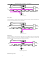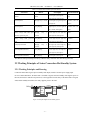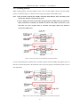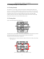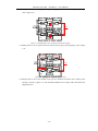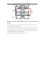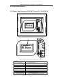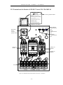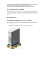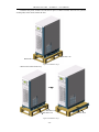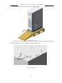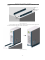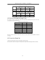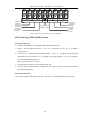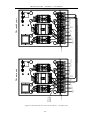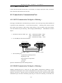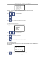
1
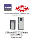
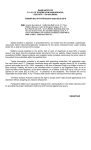
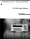
WELCOME TO USE UPS
FR-UK T Series UPS
(20-50KVA)
)
User’s Manual
【Note】
】
Please carefully read the user’s manual before operation for the sake of understanding
correct operation of the equipment. Please keep the manual handy for reference.
1. Please connect protective earth before power supply cables.
2. The input & output voltage of the UPS is dangerous which will endanger the safety.
3. Dangerous voltages are present inside the unit. Please do not open the cover of the UPS.
4. Please turn off the mains input switch and the battery switch for any urgency.
5. There are many kinds of power sources in the equipment, the line bank or the socket may still have
dangerous voltage even if the main power is disconnected.
6. Please remove the cable between the battery & UPS before repairing. It’s necessary to wait for another 5
minutes for discharging, because of the dangerous voltages.
7. The wires should be fastened to the terminals. It is prohibited to short the anode and cathode of battery.
It’s prohibited to touch any two of wire connectors or bare end of connecting wires. Otherwise, it may
lead to damage of battery or personal injury.
8. Please keep the battery away from the fire and all the equipment that may cause spark to prevent the
danger and damage.
9. Please do not open or shatter the battery, the overflow electrolyte is with causticity that may be harmful
to life.
10. Please contact the professional personnel of the local dealer or the special maintenance station for any
trouble-shooting. Random disposal of the trouble is not allowed.
11. This is an A-grade product with electromagnetic compatibility.
12. This equipment must be installed and serviced by qualified personnel.
INDEX
1. System Overview ......................................................................................................................................... 1
1.1 Introduction ......................................................................................................................................... 1
1.2 Explanation on Model Number ........................................................................................................... 1
1.3 Brief Introduction of Product .............................................................................................................. 1
1.3.1 Products Features ..................................................................................................................... 1
1.3.2 Technical Specification ............................................................................................................ 3
2. Basic Principles and Structures .............................................................................................................. 4
2.1 Working Principles of Single Unit ...................................................................................................... 4
2.1.1 Working Principle Drawing ..................................................................................................... 4
2.1.2 Working Principles................................................................................................................... 4
2.1.3 Working Process ...................................................................................................................... 6
2.2 Working Principles of Series Connection Hot Standby System ......................................................... 7
2.2.1 Working Principles and Drawing ............................................................................................. 7
2.2.2 Working Process ...................................................................................................................... 8
2.3 Working Principles of Parallel System ............................................................................................... 9
2.3.1 Working Principle .................................................................................................................... 9
2.3.2 Working Mode ......................................................................................................................... 9
2.4 How to Choose the Parallel System or Series Connection System ................................................... 11
2.5 Shape and Structure .......................................................................................................................... 12
2.5.1 Display Panel Structure of FR-UK T Series UPS(20~50KVA) ....................................... 12
2.5.2 Shape and Structure of FR-UK T Series UPS(20~50KVA) ............................................. 13
2.5.3 Terminal and Air Breaker of FR-UK T Series UPS(20~30KVA) .................................... 14
2.5.4 Terminal and Air Breaker of FR-UK T Series UPS(40~50KVA) .................................... 15
3. Transportation and Storage...................................................................................................................... 16
3.1 Transportation ................................................................................................................................... 16
3.2 Storage .............................................................................................................................................. 16
4. Installation ................................................................................................................................................. 17
4.1 Precautions During Installation ......................................................................................................... 17
4.2 Location and Environment Requirement .......................................................................................... 18
4.2.1 Location Requirement ............................................................................................................ 18
4.2.2 Environment Requirement ..................................................................................................... 18
4.3 Unpacking ......................................................................................................................................... 18
4.4 Check the External Power Supply..................................................................................................... 19
4.5 Installation of UPS ............................................................................................................................ 19
4.5.1 Installation Steps of FR-UK T Series UPS(20~50KVA) ................................................ 19
4.6 Installation of Battery Cabinet .......................................................................................................... 23
4.6.1 Important Safety Precautions ................................................................................................. 23
4.6.2 Installation Procedures ........................................................................................................... 23
4.7 Installation of Parallel System .......................................................................................................... 23
4.8 Electrical Wire Connection ............................................................................................................... 23
4.8.1 Selection of Input Breaker ..................................................................................................... 23
4.8.2 Selection of the Input and Output Cables............................................................................... 24
4.8.3 Connection of Single Unit...................................................................................................... 24
4.8.4 Connecting of Hot Standby System ....................................................................................... 25
4.8.5 The Connection of Parallel System ........................................................................................ 27
4.9 Checking and Testing of the System ................................................................................................. 27
4.9.1 Check the Electrical Wire Connection ................................................................................... 27
4.9.2 UPS Testing ........................................................................................................................... 27
4.10 Connect with the Load .................................................................................................................... 28
4.11 Connection for Communication Port .............................................................................................. 28
4.11.1 RS232 Communication Pin Signal as Following: ............................................................. 28
4.11.2 RS485 Communication Pin Signal as Following: ............................................................. 28
4.11.3 Signal Communication Pin as Following: ......................................................................... 29
5. Operation ................................................................................................................................................... 30
5.1 Precautions during Operation............................................................................................................ 30
5.2 Before Turning on ............................................................................................................................. 30
5.2.1 Calculate Loading Capacity ................................................................................................... 30
5.2.2 Do before Starting .................................................................................................................. 30
5.3 The Operation of Single Unit ............................................................................................................ 31
5.3.1 First-time Starting .................................................................................................................. 31
5.3.2 Daily Turning on/off .............................................................................................................. 31
5.4 Operating Sequence of Parallel System ............................................................................................ 31
5.4.1 Start up ................................................................................................................................... 31
5.4.2 Switching-off of Parallel Systems .......................................................................................... 32
5.4.3 On-line Launching and Exit of Parallel Systems ................................................................... 32
5.4.4 Redundancy and Expansion of Parallel Systems ................................................................... 32
6. Panel LCD Display Operation Procedure ............................................................................................... 33
6.1 Push Key Function Illustration.......................................................................................................... 33
6.2 On/Off Operation .............................................................................................................................. 33
6.3 Display and Related Operation ......................................................................................................... 33
7. Maintenance .............................................................................................................................................. 39
7.1 Maintenance of Battery ..................................................................................................................... 39
7.1.1 Daily Maintenance of Battery ................................................................................................ 39
7.1.2 Replace the Battery ................................................................................................................ 39
7.2 Maintenance Instructions .................................................................................................................. 39
7.2.1 Safety Precautions .................................................................................................................. 40
7.2.2 Regular Preventive Maintenance ........................................................................................... 40
7.2.3 Analysis and Solution to Common Problems......................................................................... 40
7.3 Trouble-shooting ............................................................................................................................... 41
7.3.1 General Description ............................................................................................................... 41
7.3.2 Trouble-shooting .................................................................................................................... 42
7.3.3 Emergency Measures ............................................................................................................. 42
FR-UK T series UPS (20-50KVA) User’s Manual
1. System Overview
1.1 Introduction
The UPS is the professional manufacturer of uninterruptible power supply and the telecommunication power
products. The company is famous with its high quality and superior performance.
1.2 Explanation on Model Number
The model number explanation of FR-UK T Series UPS(20~50KVA)is showed as Figure 1-1.
FR-UK31 **T
Output Capacity
FR-UK T Series UPS
Figure 1-1 Explanations on the Meanings of FR-UK T Series UPS(20~50KVA)
As showed in Figure 1-1,“FR-UK T **” is the FR-UK T Series on-line UPS;“**”means the output
power,when it is“30”,it means that the output power is 30KVA.
1.3 Brief Introduction of Product
1.3.1 Products Features
FR-UK T Series UPS is online sine wave UPS mainly designed for major equipment used in large-scaled
data center (such as measurement equipment, industrial automation equipment, etc.) with high performance.
Its high reliability provide necessary protection on load for the user from finance, communication, traffic, tax,
forces, security, power source, education, government and enterprise etc.
FR-UK T Series UPS is true double conversion on-line UPS. With IGBT power units, SPWM inverter,
intellectual multi modes battery management technique etc advanced tech and power management software,
owning well cost/performance rate and wide basic subscribers.
FR-UK T Series UPS main features:
True on line double conversion UPS
Output is fully isolated by transformer, with IGBT power units used to solve such problems of electric
system as lightning strike.
Reliable EMC
All products have got through EMC test in authentic facility and company. Testing items includes
conducting disturbance, radiant disturbance, conducting anti-disturbance, radiant anti-disturbance, power
fault, mass pulse, surge, ESD etc. Excellent EMC features donate FR-UK T Series to be capable for high
-1-
FR-UK T series UPS (20-50KVA) User’s Manual
frequency communication and video & audio broadcasting system.
Cold start function
Append a special current limiting circuit on UPS,user can start UPS directly with battery bank source for
emergent need in no mains status. UPS owns more powerful cold starting ability and is able to run on full
load.
Full functions LCD Display
All FR-UK T Series UPS products power over 20KVA is equipped with large LCD and daily maintenance.
Display and patented appearance can beautify user workroom. They are also very facility for user’s
operation on real time surveillance on UPS running parameters and status.
Perfect protection measures:
Protection for over output voltage and current, low battery, quick current limit and short-circuit can avoid the
stoppage caused by user’s wrong operation. Making sure stable running for devices in all status.
Intellectual battery management technology and charging power capacity extension
redundancy
Equipped with patented intellectual battery management technique. With professional management design
on battery charging or discharging, user can get high battery reliability and running life. At the same time
intellectual charging module can select right charging power according to different battery configure to make
sure rapid power compensation on backup battery bank.
Flexible network supervising
Flexible network supervising ability can realize intellectual monitoring over UPS. Including close
point-to-point communication supervising, middle range communication supervising, and remote net
management. Base on these, there are many UPS functions as real time supervising over running status and
features, automatic call, sending E-mail,cell phone message,vocal function,remote on/off UPS etc.
None-Principle-subordinate self-adaptive current equalization control technique (Only
applicable to the parallel UPS)
Adapt none-principle-subordinate self-adaptive current equalization control technique, realize N units
parallel dilatancy or N+1 redundant parallel connection, digitized current equalization control, the ability of
self-adaption is powerful, reliability and redundancy of the system is higher than traditional parallel system,
field installation and debugging is simple. UPS unit can be launched or quit on line for free, as realizing hot
maintenance on line of paralleled system.
-2-
FR-UK T series UPS (20-50KVA) User’s Manual
1.3.2 Technical Specification
Table 1-1 FR-UK T Series(20~50KVA)Technical Specification
Model
Specification
FR-UK 3120T
FR-UK 3130T
Voltage range (Vac)
Input
50±6%
Frequency range (Hz)
Three phases ,five wires
Phase
Rated power (KVA/KW)
29×12 = 348
20/16
30/24
Frequency (Hz)
50±1%(battery mode)
Wave form
THD≤ 4%(linear load)
(ms)
Battery efficiency
≥ 90%(100% linear load)
Overload capacity
105% of rated load last for 10 minutes ,125% of rated load last for 1minute
Output connector
Terminal
≤5%(only applicable to the parallel models)
Maintenance bypass switch
Available(cancel in parallel models)
Backup time
Any configuration
random extending or N+1 redundancy parallel connection
Parallel function
(only applicable to the parallel models)
LCD display
Input voltage, Frequency, Output voltage, Battery voltage, Load, DC current etc.
LED display
Operation status
Alarm function
Overload, AC input abnormal, Low battery, Failure, Over-temperature
Communication function
Features
50/40
0
Parallel equal current
Other
40/32
230±2%
Voltage range (Vac)
Switch time
FR-UK 3150T
400 (-30%~+20%)
Battery voltage (VDC)
Output
FR-UK 3140T
Protection function
Lighting arrester (optional)
RS232/RS485, dry connection communication signal
Low battery, Overload, Overheat, Output short circuit, Output over voltage
Imported 3 phases lighting arrester applied to IEC1312 protection grade
Electromagnetic compatibility
According wit h EN50091
Noise (dB)
<65(1 meter away from the front of the machine)
Cooling
Fans
Operating Temperature(℃)
0~ 40
Relative Humidity
Dimension (W×D×H)(mm)
Weight (Kg)
0~ 95%, No condensation
800×400×1180
280
300
◆ Specification are subject to change without prior notice.
-3-
380
400
FR-UK T series UPS (20-50KVA) User’s Manual
2.
Basic Principles and Structures
2.1 Working Principles of Single Unit
2.1.1 Working Principle Drawing
Maintenance Switch
AC
SOURCE
Bypass
Switch
Bypass
Filter
Filter
AC/DC
DC/AC
Transformer
TO LOAD
Contactor
Utility
Battery
Group
Figure 2-1 Working Principles Block Diagram of FR-UK T Series UPS
2.1.2 Working Principles
This UPS includes: Input Breaker, Input Filter & Protection Network, Rectifier, Inverter, Static Switch,
Bypass Breaker, Isolation Transformer, Output Filter & Battery group etc. as showed in Figure 2-1. This
system is whole digital DSP controlled on-line UPS. When the utility is normal, AC power goes through
filter and rectifier then change to DC power to inverter for charging the battery, which can be supply pure
power to load at no transfer time.
UPS is invented to protect load equipment. The power is much more reliability than utility. If the UPS is
inferior, the power may be much more unstable than utility. So you must choose a UPS that has high
efficiency and high reliability, and good service.
This system has four operation modes: utility mode, battery mode, bypass mode and maintenance bypass
mode, showed as following:
Utility Mode:
As showed in Figure 2-2, at the status of the utility normal, the rectifier changes the AC power to DC power
to inverter and charging the battery. Through the process of AC power changed to DC power, the inverter
can supply more reliability and pure power to load, as the rectifier can dispel the problems of the portent,
noise, unstable frequency and so on.
-4-
FR-UK T series UPS (20-50KVA) User’s Manual
Maintenance Switch
AC
SOURCE
Bypass
Switch
Bypass
Filter
Filter
AC/DC
DC/AC
Transformer
TO LOAD
Contactor
Utility
Battery
Group
Figure 2-2 Utility mode
Battery Mode:
As showed in Figure 2-3, when the utility is abnormity, the battery connected to DC BUS will supply power
to inverter, to protecting load from AC power interrupting.
Maintenance Switch
AC
SOURCE
Bypass
Switch
Bypass
Filter
Filter
AC/DC
DC/AC
Transformer
TO LOAD
Contactor
Utility
Battery
Group
Figure 2-3 Battery mode
Bypass Mode:
As showed in Figure 2-4, when the inverter is failure (such as over-temperature, short circuit, output voltage
abnormity, overload and so on), the inverter should shut off automatically. If the utility is normal at this
moment, the switch will switch to bypass power to supply power to load.
Maintenance Switch
AC
SOURCE
Bypass
Switch
Bypass
Filter
Filter
AC/DC
DC/AC
Transformer
Utility
Battery
Group
Figure2-4 Bypass mode
Maintenance bypass mode
-5-
Contactor
TO LOAD
FR-UK T series UPS (20-50KVA) User’s Manual
As showed in Figure 2-5, when you are maintaining or changing the battery, and the power must not be
interrupted, you can shut off the inverter, and turn on the maintenance switch, then turn off the rectifier and
bypass breaker. At this mode, AC power goes through maintenance switch to supply power to load. And at
this time, there may be no any electricity in the UPS inside, and the maintenance personnel can work without
any angst.
Maintenance Switch
AC
SOURCE
Bypass
Switch
Bypass
Filter
Filter
AC/DC
DC/AC
Transformer
TO LOAD
Contactor
Utility
Battery
Group
Figure 2-5 Maintenance bypass mode
2.1.3 Working Process
In Case of proper external power supply, there is DC voltage in the DC main circuit from DC/AC inverter to
output steady 230Vac. And external power supply will charge the battery at the same time. In case of low
voltage or sudden failure of external power supply, the battery supplies will power to the DC circuit There is
no switching time from
main supply to battery power supply. When battery is nearly out of power,
UPS will give out light and sound alarm; restrict the inverter’s operation and give out long sound alarms
while the battery is discharging electricity. UPS also has over-load protection function. In case of overload
(125% rated load), the UPS will switch to bypass status, and come back when the load is normal. In case of
severe overload (≥150% of rated load), the UPS will stop immediately inverter output and switch to bypass
status while the UPS breaker may also switch off automatically. When fault is eliminated, switch on UPS
and resume operation.
When UPS is abnormal, it will give out sound and light alarm, the UPS have alarm and protection function.
-6-
FR-UK T series UPS (20-50KVA) User’s Manual
Table 2-1 Abnormal status and alarm protection function
UPS status
Buzzer
Panel lights
Protection/Alarm
Inverter light on, line light on,
Normal
Silent
None
bypass light off, fault light off
Overload≥105%
Beeping every 1 second
Overload≥125%
Long Beeping
fault light off
minutes
Bypass light on, inverter light off
Protection after one
after 1 minute, fault light on
minute
Inverter light on, line light off,
Alarm
Beeping
and above protection point
seconds
bypass light off, fault light off
Long Beeping
Inverter light off, line light off,
protection
1
Protection after ten
Battery voltage under alarm point
Battery voltage under
every
Inverter light on, bypass light off,
point
Protection
bypass light on, fault light on
Utility input abnormal
Beeping
Over temperature (Inverter)
every
5
Line light off, inverter light on,
seconds
bypass light off, fault light off
Long Beeping
Inverter light off, line light on,
Alarm
Protection
bypass light on, fault light on
Over temperature (Rectifier)
Long Beeping
Inverter light on, line light on
Alarm
The UPS will start up and charge the battery when the utility come back after low battery protection.
2.2 Working Principles of Series Connection Hot Standby System
2.2.1 Working Principles and Drawing
Connect the main UPS’s bypass input to standby UPS output, instead of external power supply input
In case of main UPS failure, the main UPS is switched to bypass status and standby UPS supplies power to
the load, the load is in UPS inverter protection, so the equipment can run safely. If the main UPS is in bypass
status and the standby UPS failure, the utility supplies power to the load.
Li
Utility
Ni
Output
Bypass
input
Bypass
input
Standby
UPS
Main
UPS
Main input
Main input
Lo
Load
No
Figure 2-6 Principle Diagram of Hot Standby System
-7-
FR-UK T series UPS (20-50KVA) User’s Manual
2.2.2 Working Process
While working properly, main UPS supplies power to the load and standby UPS idly runs hot standby
system. As showed in Figure 2-7, thick lines refer to the power passage of hot standby system.
Note: 1. The two units of UPS by hot standby connection mode shall not share one battery pack,
instead, they shall have separate battery packs.
2. The AC input(L1,L2,L3,N) of main UPS, the bypass input of standby UPS (L,N) and the AC
input (L1,L2,L3,N) of standby UPS should be from the same utility (L1,L2,L3,N), at the
same time, the order of phase must be consistent. The bypass input (L,N) should be
connected to utility(L2,N).
Figure 2-7 Power Flow Chart of UPS Hot Standby in Normal Condition
In case of main UPS failure, the main UPS is switched to bypass status and standby UPS supplies power to
the load. As showed in Figure2-8, the thick lines refer to the power passage of hot standby system in case of
main UPS failure.
Figure 2-8 Power Flow Chart of Hot Standby System in case of Main UPS Failure
-8-
FR-UK T series UPS (20-50KVA) User’s Manual
2.3 Working Principles of Parallel System
2.3.1 Working Principle
The realization of AC power supply’s parallel current equalization is through the rapid regulation of the
single unit’s AC output wave, amplitude and phase to make them in strict conformity to one another and for
the purpose of current equalization. Any voltage amplitude or phase contrast will create very big circulating
current that in serious case may cause overload or damage to the inverter. Due to the relatively high
possibility of interference to the power of high-power UPS, the parallel system must have relatively high
anti-interference characteristic to ensure the reliable running of system.
2.3.2 Working Mode
Figure 2-9 shows block diagram of the parallel system.
BYPASS
AC
LINE
DC
DC
AC
BATTERY
UPS1
LOAD
BYPASS
AC
DC
DC
AC
BATTERY
UPS2
Figure 2-9 Block Diagram of the Parallel System
The parallel unit has a separate bypass. Two UPS’s can be paralleled directly without parallel control cabinet
and other additional public bypass input, which may facilitate installation and maintenance.
The parallel system has the following four working modes
1. Working mode in case of proper external power supply (real lines refer to UPS’s power passage),
refer to figure 2-10
BYPASS
AC
LINE
UPS1
DC
DC
AC
BATTERY
LOAD
BYPASS
AC
UPS2
DC
DC
AC
BATTERY
Figure 2-10 Working Mode in case of Proper External Power Supply
-9-
FR-UK T series UPS (20-50KVA) User’s Manual
2. Working mode in case of improper external power supply (real lines refer to UPS’s power passage),
refer to figure 2-11
BYPASS
AC
LINE
UPS1
DC
DC
AC
BATTERY
LOAD
BYPASS
AC
UPS2
DC
DC
AC
BATTERY
Figure 2-11 Working Mode in case of Improper External Power Supply
3. Working mode in case of system overload (real lines refer to UPS’s power passage), refer to figure
2-12
BYPASS
AC
LINE
UPS1
DC
DC
AC
BATTERY
LOAD
BYPASS
AC
UPS2
DC
DC
AC
BATTERY
Figure 2-12 Working Mode in case of System Overload
4. Working mode in case of one machine of the system is abnormal (real lines refer to UPS’s power
passage), referred to figure 2-13. The abnormal machine has no output, while the normal one
supply the power.
- 10 -
FR-UK T series UPS (20-50KVA) User’s Manual
natural
machine
BYPASS
AC
LINE
UPS1
DC
DC
AC
BATTERY
LOAD
BYPASS
AC
abnormality
machine
UPS2
DC
DC
AC
BATTERY
Figure 2-13 Working Mode in case of one machine abnormality
2.4 How to Choose the Parallel System or Series Connection
System
It is suggested to choose series connection system or parallel system, when the capacity of user’s need is
smaller, and need to advance the system reliability.
It is commonly suggested to choose paralleled system, when the capacity of user’s need is larger. Paralleled
system can be used for free as N piece parallel dilatancy or N+1 piece redundant parallel connection, in this
way the system reliability can be greatly enhanced. And single unit also can be launched or quit on line for
free, as realizing hot maintenance on line of paralleled system.
It should be put forward when order if the user needs the parallel system.
- 11 -
FR-UK T series UPS (20-50KVA) User’s Manual
2.5 Shape and Structure
2.5.1 Display Panel Structure of FR-UK T Series UPS(
(20~50KVA)
)
ON
OFF
PARALLEL
LINE
INVERTER
WELCOME TO USE
MODEL:
MODEL: 30KVA
INPUT:
INPUT: 400.0V/50.0Hz
OUTPUT:230.0
OUTPUT:230.0V/50.0Hz
:230.0V/50.0Hz
>>>>>>>>>>==========
BYPASS
BAT.LOW
OVERLOAD
FAULT
Figure 2-14 Display panel structure of FR-UK T Series UPS(20~50KVA)
(2)
(1)
(3)
ON
OFF
PARALLEL
LINE
INVERTER
WELCOME TO USE
MODEL:
MODEL: 30KVA
INPUT:
INPUT: 400.0V/50.0Hz
OUTPUT:230.0
OUTPUT:230.0V/50.0Hz
:230.0V/50.0Hz
>>>>>>>>>>==========
BYPASS
BAT.LOW
OVERLOAD
FAULT
(4)
(5)
(6)
(7)
(8)
(9)
(10)
(11)
(12)
(14)
(13)
Figure 2-15 Display interface of FR-UK T Series UPS(20~50KVA)
Explanation:
(1) LCD display panel
(9) Load indicator light
(2) ON button
(10) Fault indicator light
(3) OFF button
(11) Page up: for looking over the display content
(4) Parallel light
(12) Enter: for looking over the display content
(5) Utility indicator light
(13) Page down: for looking over the display content
(6) Inverter indicator light
(14) Turn back: for looking over the display content
(7) Bypass indicator light
(8) Battery indicator light
and Push to Light the LCD
NOTE: Parallel light is cancel in single unit
- 12 -
FR-UK T series UPS (20-50KVA) User’s Manual
2.5.2 Shape and Structure of FR-UK T Series UPS(
(20~50KVA)
)
Figure 2-16 Shape and structure of FR-UK T Series UPS(20~50KVA)
Figure 2-17 The front and rear panel of FR-UK T Series UPS(20~50KVA)
- 13 -
FR-UK T series UPS (20-50KVA) User’s Manual
2.5.3 Terminal and Air Breaker of FR-UK T Series UPS(
(20~30KVA)
)
Maintenance Switch
! Warning
2:1
(1)、UPS → Maintenance:
¢ Ù
、Press "OFF" key in the front-panel of UPS.
、Turn the maintenance switch to the "BYPASS" .
¢ Ú
¢ Û
、Turn off all "NFB" of the UPS.
Maintenance Switch
! Warning
1 、This switch is convenience for maintenance,
and shall be on "UPS"status when UPS
works normal.
2、This switch is operated only by professional
technician, should be operated as following :
(2)、Maintenance → UPS:
¢ Ù
、Turn on all "NFB" of the UPS.
¢ Ú
、Turn the maintenance switch to the "UPS".
¢ Û
、Press "ON" key in the front-panel of UPS.
(1)、UPS → Maintenance:
¢ Ù
、Press "OFF" key in the front-panel of UPS.
¢ Ú
、Turn the maintenance switch to the "BYPASS" .
¢ Û
、Turn off all "NFB" of the UPS.
(2)、Maintenance → UPS :
¢ Ù
、Turn on all "NFB" of the UPS.
¢ Ú
、Turn the maintenance switch to the "UPS".
¢ Û
、Press "ON" key in the front-panel of UPS.
Dismantle Cover Board
PALL.
Maintenance
Switch
(cancel in
parallel models)
cancel in parallel models
1、This switch is convenience for maintenance,
and shall be on "UPS"status when UPS
works normal.
2、This switch is operated only by professional
technician, should be operated as following :
SIGNAL
RS232/485
BYPASS
UPS
RS232/RS485
Communication
Port
Signal
Communication
Port
Paralleled
Communication
Port
N FB 2
BYPASS
N FB 3
POWER
N FB 1
BAT.
Utility Air
Breaker
Battery Air
Breaker
Bypass Air
Breaker
Terminal
L1
L2
L3
GND
Grounding
-
L
N
BATTERY
OUTPUT
DC input
Output
}
AC input
+
N
}
}
INPUT
Figure 2-18 Terminal and air breaker FR-UK T Series UPS(20~30KVA)
- 14 -
FR-UK T series UPS (20-50KVA) User’s Manual
2.5.4 Terminal and Air Breaker of FR-UK T Series UPS(
(40~50KVA)
)
Maintenance Switch
! Warning
2:1
Maintenance Switch
! Warning
1、This switch is convenience for maintenance,
and shall be on "UPS"status when UPS
works normal.
2、 This switch is operated only by professional
technician, should be operated as following :
(1)、UPS → Maintenance:
¢ Ù
、Press "OFF" key in the front-panel of UPS.
、Turn the maintenance switch to the "BYPASS" .
¢ Ú
¢ Û
、Turn off all "NFB" of the UPS.
(2)、Maintenance → UPS:
¢ Ù
、Turn on all "NFB" of the UPS.
¢ Ú
、Turn the maintenance switch to the "UPS".
¢ Û
、Press "ON" key in the front-panel of UPS.
1、This switch is convenience for maintenance,
and shall be on "UPS"status when UPS
works normal.
2、 This switch is operated only by professional
technician, should be operated as following :
cancel in parallel models
(1)、UPS → Maintenance:
¢ Ù
、Press "OFF" key in the front-panel of UPS.
¢ Ú
、Turn the maintenance switch to the "BYPASS" .
¢ Û
、Turn off all "NFB" of the UPS.
(2)、Maintenance → UPS:
¢ Ù
、Turn on all "NFB" of the UPS.
、Turn the maintenance switch to the "UPS".
¢ Ú
¢ Û
、Press "ON" key in the front-panel of UPS.
Dismantle Cover Board
PALL.
SIGNAL
RS232/485
BYPASS
Maintenance
Switch
(cancel in
parallel models)
UPS
N FB 3
POWER
RS232/RS485
Communication
Port
Signal
Communication
Port
Paralleled
Communication
Port
N FB 2
BYPASS
N FB 1
BAT.
Utility Air
Breaker
Battery Air
Breaker
Bypass Air
Breaker
Terminal
L1
L2
L3
+
N
-
GND
BATTERY
}
Grounding
}
AC input
DC input
L
N
OUTPUT
}
INPUT
Output
Figure 2-19 Terminal and air breaker of FR-UK T Series UPS(40~50KVA)
- 15 -
FR-UK T series UPS (20-50KVA) User’s Manual
3. Transportation and Storage
3.1 Transportation
It should strictly conform to the care signs during transportation, and place the UPS according to the care
signs, to avoid the shake to the UPS. It can’t put the equipment on the open vehicle and cabin, and should be
put together with flammable articles. It is prohibited to put the equipment in the open air in the midway, and
should avoid the drench of the rain, snow or other wet goods, also machinery damage.
3.2 Storage
Place the equipment according to the care signs. It should part from ground for 20cm, part from wall, hot
source, cold source, windows or air entrance for 50cm.
Environment temperature for storage is 0~40℃, relative humidity is 20%~80%, the stock should not have
any baleful gas, flammable and corrosive chemistry, have not strong shake, strike and magnetic field. The
storage period in this condition is for six months, over six months, the equipment should be checked, and
charged the battery every three months.
- 16 -
FR-UK T series UPS (20-50KVA) User’s Manual
4. Installation
4.1 Precautions During Installation
1. Before installation, check whether the circuitry is smooth, including every connection point, electrical
outlet, to avoid open circuit or short circuit.
2. For input single phase three wires, it should well grounded, ensure the voltage between neutral and ground
wire should be lower than 5V, if it is not well grounded, the voltage may be reach 100V. If the users
have the strict requirement on the voltage, pay attention to the well ground, to avoid any unnecessary
loss.
3. When install UPS, it is prohibited to connect the input and output neutral wires, line wires, and ground
wires wrongly, to avoid short circuit. In the meantime check the input voltage is normal.
4. Please follow the provided instructions and sequences while installing the battery. The wires should be
fastened to the terminals. It is prohibited to short the anode and cathode of battery. It is prohibited to
touch any two of wire connectors or bare end of connecting wires. All the misconducts may lead to
damage of battery or personal injury. Before connect the battery packs to the UPS, check whether the
battery voltage conforms to the UPS specification.
5. UPS installation requirement:
UPS must be evenly placed on the floor (avoid slanting or uneven ground);
Do not place articles on the top of UPS, No one is allowed to sit on top of UPS.
Avoid placing UPS in direct sunlight, rain or humid grounds.
Do not place the UPS in any place with erosive gases.
Figure 4-1 UPS Placement
- 17 -
FR-UK T series UPS (20-50KVA) User’s Manual
4.2 Location and Environment Requirement
4.2.1 Location Requirement
1、 Clearance
There should be no garbage or sundries around UPS because the liquid or metal improperly deposited or
suddenly fall down from other place may cause UPS short-circuit endanger power system and operator. The
dust or sundries on the vent can clumber air circulation influence fan’s work or may shut down the power
system.
2、 Fireproofing
To lessen the possibility of on fire and reduce the expense to the least, UPS room’s wall, ceiling, floor
should be made of fireproofing material and equip fire fighting equipment (such as Portable CO2 fire
extinguisher).
3、 Air circulation and heat elimination
To easily operator, maintenance Inverter and eliminate Inverter inner heat, there should be at least 50-70 cm
room around UPS frame and 50 cm room above it. Also electronic fan should be installed near the battery to
keep the house in good air circulation. Only operate in the normal temperature (20°C), battery life will be the
longest.
4.2.2 Environment Requirement
Environment temperature:0℃~+40℃;
Relative humidity:0%RH~95%RH,no condensation;
Cooling:Air-cooled;
Altitude:Meet international standard;
Uprightness: There shall be no shock and the inclination shall no be over 5º;
Pollution grade:Ⅱ;
UPS must be installed in an environment that has enough wind, cool, not high humidity and clean air.
Operation temperature for recommended is 20~25℃, and humidity is about 50%.
Note:
It is prohibited to be installed in an environment that has metal electric dust.
4.3 Unpacking
Both UPS and its fittings (battery) are packaged in wooden cases or cartons, so when unpack the UPS, the
operator should be careful and see if there is any damage. Before clear away the package material, make sure
all the fittings have been found.
- 18 -
FR-UK T series UPS (20-50KVA) User’s Manual
If the equipment and its fittings have damaged during the transportation or are not fit with the goods listed in
the contract, please note on spot and contact with the representative of our local office.
If the UPS is found machinery damage, or the external damage, further inspection will be needed.
4.4 Check the External Power Supply
Check the load capacity of the power net, to ensure it can meet the equipment’s requirement, and to make
sure it conforms to the voltage and frequency on the equipment’s nameplate. Check whether the load
capacity decline because of the aging of the wire. If any doubt, please consult with the local electricity
department.
4.5 Installation of UPS
4.5.1 Installation Steps of FR-UK T Series UPS(
(20~
~50KVA)
)
Move the UPS to the ground from the wooden pallet. The FR-UK T Series UPS(20~50KVA)can be
installed as following:
1. Unpack the FR-UK T Series UPS(20~50KVA), the shape and structure is below:
Figure4-2 Installation step 1
- 19 -
FR-UK T series UPS (20-50KVA) User’s Manual
2. Release four pieces of M16×65 bolts and six pieces of M12×40 bolts where the feet joins the
wooden pallet, let the wheels contact the floor.
Bolts M12×40
Bolts M16×65
Figure 4-3 installation step 2
3. Remove the anchor frame away.
Bolts M12×80
Bolts M12×40
Figure 4-4 Installation step 3
- 20 -
anchor frame
FR-UK T series UPS (20-50KVA) User’s Manual
4. Push the UPS from wooden pallet to the floor by using the slope.
Figure 4-5 Installation step 4
5. Select and arrange the installation location, drive 4 M10 expansion bolts into the ground, space
between is 410mm×525mm, the revealed height should be within 50mm:
M10 expansion bolts
Figure 4-6 Installation step 5
- 21 -
FR-UK T series UPS (20-50KVA) User’s Manual
6. Mount the T type anchor frame,fix the gasket Φ10, spring gasket Φ10 and nut M10,fasten as
following:
gasket Φ10
spring gasketΦ10
nut M10
T type anchor frame
Figure 4-7 Installation step 6
7. Move the UPS into anchor frame, prop up it again by the 4 pieces M16×65 bolts, and then fix the
main UPS with anchor frame with 6 pieces of M12×40,as following:
Figure 4-8 Installation step 7
- 22 -
FR-UK T series UPS (20-50KVA) User’s Manual
4.6 Installation of Battery Cabinet
FR-UK T Series UPS would be matched battery and battery cabinet except the main unit.
4.6.1 Important Safety Precautions
It is prohibited to prize up or break down the battery, because the electrolyte do harm to our skin and eyes.
Please advert the following safe precautions when replacing the battery to avoid getting an electric shock and
short circuit.
1)
Don’t gird the watch, ring or any other metal decorations.
2)
Using the tools with insulated holds.
3)
Don’t put tools and metal articles on the battery.
4)
Keep the fire source away from the battery, no smoking.
4.6.2 Installation Procedures
1. To ensure safe operation and avoid the damage to the equipment, it is required to install the battery by
professional personnel, and implement the following procedures:
1)
Connect the external battery groups, don’t join into the UPS battery input terminal.
2)
Connect the AC Wire into UPS, ensure the polar is correct and the voltage conforms to the UPS
technical specification.
2. Turn on UPS when AC input normal and UPS empty load, check the DC voltage in battery input terminal.
3. Turn off UPS after checking the charging voltage is normal, join the battery packs, and ensure the polar is
correct of UPS and battery cabinet.
4.Check everything is OK after mounting.
4.7 Installation of Parallel System
1. Assemble the single unit of parallel system separately according to the above installation procedure, then
connect the single unit’s AC output to the distribution box.
Note: the connection and phases of single unit AC input should be strictly consistent, and the bypass
phases of the parallel system should be identical.
2. Connect all the parallel port with the communication wires, and fasten the RS232 with the bolts
4.8 Electrical Wire Connection
4.8.1 Selection of Input Breaker
To isolate with the utility, the breaker or distribution box with the adaptive power should be equipped before
the equipment’s input wire. The breaker should be 1.5~2 times of the UPS maximal input currency, and
can’t adopt the breaker with the creepage protection, to avoid the wrong operation. It is suggested to make
- 23 -
FR-UK T series UPS (20-50KVA) User’s Manual
the distribution box by the professional company, please refer the selection of breaker to Table 4-1.
Table 4-1 choice of air breaker
FR-UK T 20
FR-UK T 30
maximal
currency(A)
recommended
breaker(A)
maximal
currency(A)
recommended
breaker(A)
AC input
70
100
105
200
DC input
70
100
105
200
FR-UK T 40
AC input
DC input
maximal
currency(A)
140
140
recommended
breaker(A)
200
200
FR-UK T 50
maximal
currency(A)
165
165
recommended
breaker(A)
200
200
4.8.2 Selection of the Input and Output Cables
The selection of UPS AC input cable, output cable and battery connecting cable, please refer to the
recommended sections listed in Table 4-2.
Table 4-2 choice of cables area(mm2)
FR-UK T 20
FR-UK T 30
AC input(line, neutral)
35
35
AC input(ground)
10
10
DC input(+, -)
25
25
AC output (line, neutral)
25
25
AC output(ground)
10
10
FR-UK T 40
FR-UK T 50
AC input (line, neutral)
50
50
AC input(ground)
16
16
DC input(+, -)
35
35
AC output (line, neutral)
50
50
AC output(ground)
25
25
The above section is for the wire about 5m, if the wire is above 20m, the section should be increased
accordingly.
4.8.3 Connection of Single Unit
Connect the provided cables into the corresponding terminal and fasten.
Note: Ensure the connection of input wire and output wire, input terminal and output terminal is fastened.
- 24 -
FR-UK T series UPS (20-50KVA) User’s Manual
L1
L2
The line wire
of input(L1)
The line wire
of input(L2)
The line wire
of input(L3)
The Neutral wire
of input(N)
L3
+
N
GND
INPUT
-
BATTERY
L
N
OUTPUT
The ground wire
of input & output
The Neutral wire
of output(N)
The Line wire
of output(L)
The cathode
of battery
The anode
of battery
Figure 4-9 Connection of FR-UK T Series UPS(20~50KVA)
4.8.4 Connecting of Hot Standby System
4.8.4.1 Connecting steps
1
Dismantle the terminal’s covering board of main UPS and standby UPS.
2
Remove the wires connection between “L”&“N”of “BYPASS” and“L2”&“N”of “INPUT”
of the main UPS.
3
Connect the “L” of “BYPASS” in main UPS terminal to the “L” of “OUTPUT” in the standby UPS
terminal by red wire; and connect “N” of “BYPSS” in main UPS terminal to
the “N” of “OUTPUT”
in standby UPS terminal by blue wire.
Note: be sure not short to “L” and “N”.
4
The remaining connecting is the same with the single unit.
5
Check the above steps and confirm everything is OK, lock up the terminal covering board on the main
UPS and the standby UPS.
4.8.4.2 Connecting mode
1. The connecting mode of FR-UK T Series UPS(20~50KVA)hot standby as showed in Figure 4-10.
- 25 -
- 26 -
Terminal
Short wires
that should be
dismantled
Figure 4-10 Connection of FR-UK T Series UPS(20~50KVA) hot standby system
L3
INPUT
L2
N
The
The line wire of neutral
input(L3)
wire of
The line wire of
input
The line wire input(L2)
of input(L1)
L1
N FB 3
POWER
N
Terminal
L3
INPUT
L2
N
The
ground
wire of
input &
output
GND
N FB 2
BYPASS
The
The line wire of neutral
input(L3)
wire of
The line wire of
input
The line wire input(L2)
of input(L1)
L1
N FB 3
POWER
-
SIGNAL
N
RS232/485
OUTPUT
L
N FB 1
BAT.
The anode The cathode
of battery of battery
BATTERY
+
PALL.
The standby unit
Two short wires connected output of standby unit and bypass input of main unit
The anode The cathode
of battery of battery The line wire
The neutral
of output
wire of output
L
OUTPUT
The
ground
wire of
input &
output
-
RS232/485
BATTERY
+
N FB 1
BAT.
SIGNAL
GND
N FB 2
BYPASS
PALL.
The main unit
FR-UK T series UPS (20-50KVA) User’s Manual
FR-UK T series UPS (20-50KVA) User’s Manual
4.8.5 The Connection of Parallel System
PALL.
SIGNAL
RS232/485
PALL.
SIGNAL
RS232/485
KH02
Terminal
L1
L2
Terminal
L3
INPUT
+
N
GND
-
BATTERY
The neutral
wire of input
The line wire The line wire
of input(L1) of input(L3)
The line wire
of input(L2)
L
N
L1
OUTPUT
L2
L3
INPUT
+
N
GND
-
BATTERY
L
N
OUTPUT
the neutral wire of output
the line wire of output
LOAD
Fig.4-11 connection of FR-UK T Series UPS(20~50KVA) paralleled system
4.9 Checking and Testing of the System
4.9.1 Check the Electrical Wire Connection
1. Check the AC input wire: if AC input wire’s colour system is standard, if the section of AC input wire is
suitable, if connect with the external control switch, if the connection is correct and fasten.
2. Check AC output wire: if the AC output wire’s colour system is standard, if the section of AC output wire
is suitable, if the connection is correct and fasten.
3. Check the ground wire: if the ground wire connects with the ground wire terminal of the house, if the
connection is fastening and safe.
4. Check the voltage between neutral wire and ground wire. It should be lower than 5Vac.
5. Check the connection of RS232 port if the UPS mount remote control monitor.
6. Check if the wiring is neat and tidy, if wire binding complies with technical standards.
7. Check if the installation and wiring is convenient for future modification, expansion and maintenance.
4.9.2 UPS Testing
Turn off the bypass input switch or AC input switch to simulate the situation of the utility fail, the “LINE”
LED light will turn off and the buzzer will sound for every 5 seconds.
- 27 -
FR-UK T series UPS (20-50KVA) User’s Manual
4.10 Connect with the Load
Connect with the load when the UPS starts to work normally, if it displays output power 100%, it means the
UPS is full loaded, and should lessen some load.
4.11 Connection for Communication Port
4.11.1 RS232 Communication Pin Signal as Following:
:
UPS supply a standard RS232 communication port, FR-UK T Series UPS supervising software,SNMP card
is optional for UPS communication( no more than 10m generally);Realizing remote control over UPS
input voltage, input frequency, output voltage, output frequency, load etc parameter and remote machine
on/off. The definition on pin as following:UPS end supply standard DB9 port (RS232/RS485 in common
adapter).
1. Definition for UPS end(DB9)pin: 6pins communication adapter(RXD)
7pins communication land (GND)
9pins communication sending (TXD)
2. PC end (DB9) pin follow RS232 definition.
5 4 3 21
1 2 3 45
9 8 7 6 M2502 Interface Cable 6 7 8 9
UPS side (9 Pin)
PC side (9 Pin)
3. data transmitting way:
Asynchronous transmitting in Series
Beginning at 1 digit
Data at 8 digits (low digit ahead)
1 Stop digit
No verify
Speed for communication port data transiting 2400 bit/s.
4.11.2 RS485 Communication Pin Signal as Following:
:
Standard communication port on UPS also can support RS485 communication standard for remote
communication. Realizing the remote control on UPS parameter for input voltage, frequency, output voltage,
frequency, and load etc. Allowing remote on/off machine operation. By the connection between RS485
communication port and UPS concentrating supervising can realizes the monitoring on muti-UPS. The
- 28 -
FR-UK T series UPS (20-50KVA) User’s Manual
definition of RS485 pins as following:
5----------------------------------RS485 data communication “ +”
end
7----------------------------------RS485 data communication “ GND”
end
8----------------------------------RS485 data communication “-” end
4.11.3 Signal Communication Pin as Following:
:
UPS supply signal communication with two isolations. It stands for low battery, utility abnormal, its status is
as following:
Battery normal, 1-2P break;low battery ,1-2P connected;
Utility normal,3-4P break;utility abnormal,3-4Pconnected;
- 29 -
FR-UK T series UPS (20-50KVA) User’s Manual
5. Operation
5.1 Precautions during Operation
1. Check the load before turning on, the user’s load should not exceed the UPS rated power, otherwise, it
will result in UPS overload protection or bypass working.
2. It is prohibited to use the UPS panel switch as the load power switch, turn on/off UPS as following: turn
on UPS panel power switch, then turn on load power switch when starting up, turn off load power switch,
then turn off UPS power switch when turning off. Don’t start up UPS frequently.
3. Usually one should wait till the UPS is running smoothly before turning on the loaded equipment, first
turning on the higher power equipment, then the lower power equipment. Some equipment requires very
high starting currents (as some brands of monitors), and they might cause overload protection (as
bypassing). Such equipment had better be turned on before other equipment.
4. If the UPS work with generator, turn on generator firstly, turn on UPS after generator work smoothly,
otherwise it will damage to UPS or equipment. Also cut down the connection before turning off.
5.2 Before Turning on
5.2.1 Calculate Loading Capacity
FR-UK T Series UPS calculates loading capacity based on 80% resistance loading of nominal rated power.
Usually the largest loaded number N bearable with computer is calculated according to the following
formulae:
n
∑ Pi≤P
i=1
in the equation, P stands for UPS output capacity (VA), Pi is VA of No. i load.
Example: a user has the computer equipment of the following nominal powers:
IBM PC: 230V/1.5A(345VA)
LQ1600K printer: 230V/1.0A(230VA)
14-inch color monitor: 70W
Total power: 345VA + 230VA + 70/0.6VA = 690VA
The selected UPS with nominal power of 30KVA will sustain 43~45 sets of above computer equipment.
5.2.2 Do before Starting
In order that the UPS operates normally, make sure of the following before starting the machine:
1. Input and output are correctly installed;
- 30 -
FR-UK T series UPS (20-50KVA) User’s Manual
2. The breaker on the front of UPS is in OFF position;
3. Input power supply end is connected with rated input power;
4. Output of UPS is not short-circuited and self-loaded capacity is not more than UPS capacity;
5. Make sure the computer or other equipments are turned off.
5.3 The Operation of Single Unit
5.3.1 First-time Starting
After making sure that the above items are all correct, please start up UPS by the following methods:
1. Turn on the switches by the following order:
Power →bypass→battery switches
2. Press UPS display panel ON key, then UPS will start up gradually, Conversion indicator will light up,
after some delay, Bypass light will go out, UPS converts to inversion supplies, by now starting procedure is
finished, UPS begins operation, then turn on the computer or other equipments.
3. Turn on the computer or other equipments to operate on.
5.3.2 Daily Turning on/off
In daily routine uses, please follow the methods below for operation:
Press “ON” key on the display panel; after about 20 seconds, turn on the computer or other equipments.
Before turning off, please turn off the computer or other equipments firstly, then press the OFF on the
display panel for two seconds to turn off.
Usually one should wait till the UPS is running smoothly before turning on the loaded equipment, first
turning on the higher power equipment, then the lower power equipment. Some equipment requires very
high starting currents (as some brands of monitors), and they might cause overload protection (as bypassing).
Such equipment had better be turned on before other equipment.
5.4 Operating Sequence of Parallel System
Do not start up load before the parallel system is not yet started. Make sure that each breaker of parallel
output distribution box is off.
5.4.1 Start up
1
After making sure of correct installation, start up each parallel unit separately as per single unit’s
startup sequence.
2
After each parallel unit has inverted output, measure each unit’s inverter voltage and the difference
- 31 -
FR-UK T series UPS (20-50KVA) User’s Manual
between highest and lowest voltages should not be over 5V, switch on the parallel unit’s breaker on the
distribution cabinet, the measured circulating current of parallel unit should not be fewer than 3A.
3
Switch on the general output breaker and each shunt output breaker, then start up load equipments one
by one.
5.4.2 Switching-off of Parallel Systems
Normally, it is not recommended to frequently switch on/off the parallel system.
1
Switch off all loads
2
Switch off all parallel units one by one.
3
Switch off relevant breaker of each unit (it can remain on during normal switching on/off).
5.4.3 On-line Launching and Exit of Parallel Systems
1. In case of any parallel unit’s faults, this unit will automatically exit the parallel system with sound and
light alarms; the user can fully launch out this unit by switching off this unit on the panel, inputting
external power into air switch and switching off this unit’s air switch in the parallel distribution cabinet.
On-line hot maintenance and replacement is realized.
2. In order to realize on-line launching of one or several units, what is needed is to finish the input and
output connection of these units, switch on the relevant air switch on parallel distribution cabinet and
then start these units on by one. These units will automatically launch themselves and work with
balanced current.
Note: while the parallel system is working normally, do not launch out a unit without shutting down the
parallel unit, or the equipment running might become abnormal..
5.4.4 Redundancy and Expansion of Parallel Systems
1.
Redundancy
When N+1 standby redundancy design is adopted, the total output power shall not be bigger than N
times single unit rated power. In case of fault of any single unit, this backup unit can be freely
launched in/out without interfering with the system’s running to improve the system’s reliability.
When output goes beyond the above load, the overloaded unit (over N/(N+1) times of single unit’s
rated power) will give out alarm. For example, regarding double backup system, overload alarm will
be given when any single unit is over 50% overloaded.
2.
Expansion
Unless in special cases, total output power is not to be increased by paralleling.
- 32 -
FR-UK T series UPS (20-50KVA) User’s Manual
6. Panel LCD Display Operation Procedure
Panel LCD can display UPS all kinds of running parameter and status. It is operation interface to set some
parameter for UPS and control UPS. Whole LCD display apparatus can display 5 lines characters. More than
5 lines character content can be displayed by up and down paging. Elegant operating buttons are facility for
user operation.
6.1 Push Key Function Illustration
This Series UPS owns 4 functions keys, as following:
This key is “ display upward / parameter setting +”function repeat.
Add parameter at parameter setting.
Push this key mean“ display downward / parameter set.
For muti-lines character display, downward browsing.
At parameter setting, reduce parameter.
Push this key to confirm the function.
To confirm the option with“>” mark or parameter set.
Push this key to back to previous page.
For back to upper level operation menu or parameter setting without input.
Push to Light the LCD.
6.2 On/Off Operation
This Series UPS On/Off keys:
Power on:Push
Power off:Push
.
.
key about 2S.
6.3 Display and Related Operation
1. UPS bypass shut off and power on, panel LCD display:
WELCOME TO USE
MODEL:
MODEL: 30KVA
30KVA
INPUT:
INPUT: 400
400.0V/50
.0V/50.0
V/50.0Hz
.0Hz
OUTPUT:
OUTPUT:230.0V/50
.0V/50.0
V/50.0Hz
.0Hz
>>>>>>>>>>==========
Around 10 seconds later turn into normal display.
- 33 -
FR-UK T series UPS (20-50KVA) User’s Manual
This Series UPS defaults on output parameter to be normal display page. If no touching any key after power
on or in 30S,LCD display will turn into output parameter display.
UPS
OU TPUT :
2 3 0 .0 V
FR EQUENC Y : 50 . 0 Hz
UP S :
NO RMAL
20 04/08/ 28 09: 00:00
UPS information:
POWER OFF
RECT. FAIL
In this page, Push
NORMAL
BAT. LOW
OVERLOAD
PHASE ERR.
LINE FAIL
INV. FAULT
Key into function menu, other keys are negative.
2. Function menu:
This page supply all UPS functions display in menu list, “>” mark your present selected function.
> RECTIFIER DATA
BYPASS DATA
OUTPUT DATA
BATTERY DATA
WORKING STATUS
By the way,there are these options as following:
BUZZER CONTROL
BATTERY TEST
LANGUAGE SETTING
DATA&TIME SETTING
HISTORICAL EVENT
Push
keys to move “>” mark to the selection in menu.
The mark on right up or down of screen stands there is still some matter for up or down rolling.
Push
Push
key into the menu with “>” mark.
key to turn in output parameter normal display page.
- 34 -
FR-UK T series UPS (20-50KVA) User’s Manual
3. Rectifier parameter page:
This page displays UPS rectifier 3 phases input voltage, frequency and rectifier DC output voltage.
RECTIFIER DATA
R-N:
230.0Vac
S-N:
230.0Vac
T-N:
230.0Vac
DC VOLTAGE:403.0V
Push
key to back upper menu. Other keys are negative.
4. Bypass parameter page:
This page displays UPS bypass voltage and frequency.
BYPASS DATA
BYPASS:
230.0Vac
FREQUENCY: 50.0Hz
Push
key to back upper menu. Other keys are negative.
5. Output parameter page:
This page displays UPS 3 phases output voltage and percentage for each phase.
OUTPUT DATA
OUTPUT:
230.0Vac
FREQUENCY: 50.0Hz
LOAD:
100%
Push
key to back upper menu. Other keys are negative.
6. Battery parameter page:
This page displays UPS battery voltage and charging/discharging current. When UPS in normal status,
displaying charging current; When UPS in inverting status, displaying discharging current.
Push
key to back upper menu. Other keys are negative.
BATTERY DATA
VOLTAGE:
CHARGE:
403.0V
5.0A
- 35 -
FR-UK T series UPS (20-50KVA) User’s Manual
7. Working status:
This page displays all UPS running status.
PHASE: NORMAL
RECTIFIER: NORMAL
BATTERY: NORMAL
INVERTER: NORMAL
BYPASS: NORMAL
By the way, there are three lines in this page. Displayed by the mark at right down of screen.
OUTPUT: ON INV.
LOAD STATUS: NORMAL
TEMPERATURE: 26.0(C)
Push
keys to browse by scroll.
Push
key to back upper menu. Other keys are negative.
8. Buzzer silence control page:
This Series offer UPS silence control ability, When UPS stay in no utility input status, user can buzz off
intermission beeping. But if abnormal status initiated, buzzer will start alarming automatically without shield
control.
BUZZER CONTROL
STATUS: OFF
>BUZZER ON
BUZZER OFF
Push
keys to select on/off.
Push
key to confirm your selection.
Push
key to back upper menu. Other keys are negative.
9. Battery test control page:
This Series supply UPS battery test function, the principle for it is lower DC input voltage for inverter to
give UPS battery a instant discharging to test battery validity under long term utility status.
- 36 -
FR-UK T series UPS (20-50KVA) User’s Manual
BATTERY TEST
STATUS: OFF
>ABORT TEST
GENERAL TEST
DEEP TEST
By the way, another line in this page, can be displayed in the mark at right down of screen.
DEEP TEST
Push
Push
Push
keys to control mark,
key to confirm your selection.
key to back upper menu. Other keys are negative.
10. Language selection presetting page:
This page can select screen information in Chinese or English.
LANGUAGE
>中 文
ENGLISH
Push
keys to select on/off.
Push
key to confirm your selection.
Push
key to back upper menu. Other keys are negative.
11. UPS internal time adjusting:
This Series UPS equipped with timer chip. It can offer present time. By this page, user can adjust time for
UPS timer chip.
DATE&TIME SETTING
DATE: 2004/01/01
TIME: 09: 00: 00
Push
key to select year, month, date, hour, minute, second.
- 37 -
FR-UK T series UPS (20-50KVA) User’s Manual
Push
Push
upper menu.
Keys to add or reduce time meters.
key to confirm adjusted time parameter and input UPS internal time chip, then back to
12. Version message:
This page can supply the information of UPS type name, version and device ID address.
ID address supply UPS address code information of communication data at adopting RS485 multi-machines
supervising. A Series dial switch in UPS can preset it. Generally it is not supported to change these
parameters.
MO DEL : 30 KVA
VE RSION: 1.00
ID :
01
Push
key to back upper menu. Other keys are negative.
13. History page:
This page can supply subscriber display and record of some important history parameter and time for UPS.
They are the basic information for analysis on local power network and abnormal situation.
AC FAIL CNT: 0
BAT LOW CNT: 0
OVERLOAD CNT: 0
AC HIGH CNT: 0
Push
Push
Push
keys to do rolling browsing.
key to back upper menu. Other keys is negative.
+
keys for 10 seconds to clean the history record in UPS memory. But account
on the analysis for fault later ,so recommended to keep the history data record.
- 38 -
FR-UK T series UPS (20-50KVA) User’s Manual
7. Maintenance
7.1 Maintenance of Battery
7.1.1 Daily Maintenance of Battery
1. Charge the battery for 4 hours every three months if it is not used for a long time.
2. Charging the UPS for 4 hours before using, the UPS can be used while charging, but if the utility fail at
that time, the backup time may be less than the standard value.
3. The battery should charge and discharge every four or six months when normally using. The standard
models should charge after overload protection, and the charging time should be less than 4 hours.
4. In high temperature district, the battery should charge and discharge every two months, the standard
models’ charging time should be less than 4 hours.
5. It is prohibited to mix use different capacity, different type and different manufacturer’s battery.
6. Use the dishcloth with clean water to clean the battery crust, it is not allowed to use oil or organic
chemistry such as gasoline or thinner.
7. Keep the battery or battery pack away from fire source, to avoid any unnecessary losses.
8. Check the charger regularly, to avoid the situation of over-charge or not complete charge. Don’t over
discharge the battery, full charge the battery after discharge (no more than 24 hours), it is not allowed to
discharge the battery when it is not full charge, otherwise it will reduce the battery capacity, even damage
the battery.
9. Turn off the switch after stop using the UPS, to avoid over discharge after power cut.
7.1.2 Replace the Battery
1. Don’t throw the battery into water.
2. Don’t open up or break down the battery, the electrolyte will do harm to skin and eyes.
3. Take back the batteries according to the relative explain.
4. Replace the battery with the same type and same grade battery.
5. Replace the whole battery pack, don’t use the new battery with the worn battery.
6. Please note the following items when replace the battery:
Dangerous voltage exist between battery terminal and ground, please test before touch.
7.2 Maintenance Instructions
Correct maintenance, including preventive and remedy maintenance, is key to optimal operation of UPS and
will prolong the equipment’s life span. Preventive maintenance includes some frequently executed
procedures which are for the prevention of system faults and maximization of system efficiency; remedy
maintenance includes trouble-shooting of the system for effective maintenance.
- 39 -
FR-UK T series UPS (20-50KVA) User’s Manual
7.2.1 Safety Precautions
In order to carry out system maintenance safely and successfully, the relevant safety precautions must be
carried out. Essential tools and testing equipment shall be used and qualified maintenance staff shall
participate. The following safe operation procedures shall be observed at any time:
1.
Bear in mind that there is dangerous voltage in UPS even if it is not running.
2.
Make sure that the operation and maintenance staff of UPS is familiar with the equipment and this
manual.
3.
Do not wear gold or silver ornaments like rings and watches, etc during operation of UPS.
4.
Do not take for granted the safe operation procedures. If you have any questions, please consult those
who are familiar with the equipment.
5.
Look out for the dangerous voltage in UPS. Before maintenance and adjustment, use a voltage meter
to ensure that the power supply is switched off and it is safe for operation.
7.2.2 Regular Preventive Maintenance
The following is the steps of preventive maintenance which after execution will increase the efficiency and
reliability of UPS system.
1.
Maintain a clean environment to avoid dust or chemical pollution to the UPS.
2.
Wiring.
Check once half a year if the input and output terminals have good contact.
3.
Check regularly the operation of draught fans to prevent choking of draught. They shall be replaced in
case of damage.
4.
Check regularly battery voltage and UPS working status.
7.2.3 Analysis and Solution to Common Problems
In case of improper operation after UPS startup, do not diagnose it to be UPS fault, do the following to see if
it works.
Phenomenon 1
External power supply is all right, UPS outputs AC 230V after startup, battery is in inverter status and
buzzer gives off intermittent alarms.
Possible cause: Intermittent AC input due to bad contact between all terminals and sockets, etc.
Phenomenon 2
After installation of UPS, fusing or tripping will occur when power supply is switched on or UPS “On”
button is pressed.
- 40 -
FR-UK T series UPS (20-50KVA) User’s Manual
Possible cause: the five input phase wires are wrongly connected, e.g. null wires or line wires are connected
to UPS grounding wires (machine casing), or the three output wires are wrongly connected.
Phenomenon 3
UPS outputs AC 230V after startup, but it works in bypass status (“Bypass” indicator light is on)
Possible cause: load is bigger than UPS rated power. It is necessary to reduce load or choose UPS of bigger
power capacity. It is still normal operation if bypass status is actuated by startup of load and disabled
automatically.
Phenomenon 4
UPS display and output are proper after startup, but output stops immediately after load is connected.
Possible cause:
(1) UPS is seriously overloaded or output has short circuit. It is necessary to reduce load to applicable
value and find out the cause of short circuit. It is most commonly due to output transfer socket short circuit
or input short circuit due to equipment damage.
(2) The startup sequence from equipment of bigger power to smaller power is not followed. UPS shall be
restarted. After UPS is in normal operation, start the equipment in the above sequence.
Phenomenon 5
UPS has been in proper operation for some time before it shuts down automatically.
Possible cause: Battery unit is not charged in time and it is working and discharging (when external power
supply fails or is not connected). In the end UPS battery under voltage protection is actuated.
Warning: in case of UPS battery under-voltage protection, all switches shall be switched off. Restart UPS
and recharge battery pack when external power supply resumes. Long-term low voltage may affect battery’s
life span.
Phenomenon 6
UPS has been in operation for some time and input display has been all right before the buzzer alarms
intermittently and battery under-voltage is displayed.
Possible cause: Caused by too low power supply voltage. UPS is working in battery supply status then
trigger battery under-voltage protection.
Phenomenon 7
When external power supply is cut, UPS has no output.
Possible cause: Battery unit is not connected with main unit or battery unit is low voltage or seriously
damaged.
7.3 Trouble-shooting
7.3.1 General Description
In case of any fault, look for the evident damage and try to find out if the fault is caused by the system itself
or external environment (like temperature, humidity and load). All these external factors shall always be
checked before coming to the conclusion that it is due to UPS system damage.
- 41 -
FR-UK T series UPS (20-50KVA) User’s Manual
7.3.2 Trouble-shooting
This part only contains some simple ways for trouble-shooting. If the diagnosis is not quite sure or the
acquired information is not sufficient for solving the problem, please contact local representative office or
distributors.
1. Buzzer gives off long alarms and fault indicator light is on, UPS is in bypass status and inverter is not
working properly.
Possible cause: (1) Overload or short circuit, UPS is shut down automatically for protection
(2) Drive or power tube fault
(3) Main control panel fault
(4) DC fuse broken
2. UPS is working properly but can not work in case of external power failure.
Possible cause: (1) Battery fault
(2) Battery charger fault and can’t charge the battery
(3) Battery wires are not connected or wiring terminals have bad contact.
(4) UPS is not working and it is normally in bypass output status
(5) UPS battery control switch is off
3. UPS input is all right while buzzer still gives out intermittent alarms
Possible cause: Bypass input air switch is not on so that system can detect input signals from external
power supply; input voltage is abnormal which exceeds UPS’s permitted input
voltage range.
4. UPS is in normal operation with computer load. However, after electricity cut-off, UPS is still working
normally while computer is down.
Possible cause: it has bad grounding. It is due to the high floating voltage between null wires and
grounding wires.
5. No indicator lights on the panel.
Possible cause: bad contact or fault of display control board.
6. UPS is in normal operation without load. However, when the load is start, UPS is failure and work in
bypass status.
Possible cause: the one drive signal of IGBT is lost.
7.3.3 Emergency Measures
1. Emergency Measures for single unit
Press the “OFF” button on the panel to shut off the UPS when the single UPS is failure. If it is necessary,
disconnect the load and turn off the input/output breaker for more to protect the UPS.
2. Emergency Measures for hot standby system when the main unit is failure or the standby unit is failure.
- 42 -
FR-UK T series UPS (20-50KVA) User’s Manual
Press the “OFF” button on the panel of main unit to shut off the UPS when the main unit is failure. And turn
off its the utility breaker and battery breaker. Then ask authorized professional maintenance personnel for
help.
Press the “OFF” button on the panel of standby unit to shut off the UPS when the main unit is failure. And
turn off its the utility breaker and battery breaker. Then ask authorized professional maintenance personnel
for help.
3. Emergency Measures for paralleled system that single unit single unit is failure.
Press the “OFF” button on the panel of standby unit to shut off the UPS when the single unit of paralleled
system is failure. Then turn off its the input breaker, output breaker and battery breaker. And ask authorized
professional maintenance personnel for help.
- 43 -
0LD0503020000000