1
TP -20214
Revised 10 -05
MERITOR WABCO
Enhanced Easy -StopTM
Trailer ABS 2S /2M, 4S /2M and
4S/3M Premium with
Installation Guide
Hazard Alert Messages
PLC
If
Read and observe all Warning and Caution hazard alert messages in
this publication. They provide information that can help prevent
serious personal injury, damage to components, or both.
How to Obtain Additional Maintenance
and Service Information
-
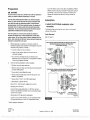
this assembly
the trailer
BU
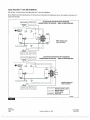
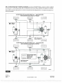
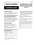
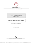
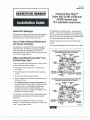
Installation Instructions
is
mounted facing forward
-
toward the front of
the YE sensor connections go to the curbside and the
sensor connections go to the roadside.
If
this assembly
is
mounted
facing the rear, the YE sensor connections go to the roadside, and the
BU
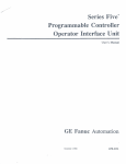
sensor connections go to the curbside. Figure 1.
All premium systems use the same ECU /dual modulator valve
assembly.
The ECU /dual modulator assembly cannot be used as a 2S/1 M system.
Refer to Maintenance Manual MM -0180, Enhanced Easy -StopTM
Trailer ABS with PLC, and Maintenance Manual 33, Easy -StopTM
Trailer ABS. To obtain these publications, call ArvinMeritor's
ECU /DUAL MODULATOR VALVE MOUNTED WITH
SENSORS FACING FRONT OFTRAILER
Customer Service Center at 800 -535 -5560, or visit the Tech Library
CURBSIDE
on our website at meritorwabco.com.
Differences Between Easy -StopTM and
Enhanced Easy -StopTM
There are some changes to Enhanced Easy -StopTM that you need to
SUPPLY
PORT
Enhanced Easy -StopTM includes Power Line Communication
(PLC) function.
The ECU /dual modulator valve assembly must be mounted as
one unit.
ABS lamp on the trailer.
It is
ROADSIDE
SUPPLY
PORT
tat
PORTS
DELIVERY
ROADSIDE
/
sV.
Crsiek
fr
The valve portion of the ECU /dual modulator valve assembly contains
-I¡ßÿ (Th
two separate modulator valves that share common control and
DELIVERY
ROADSIDE
whether the valve is facing the front or the rear of the
EXHAUST
PORT
determines sensor hookup.
Figure
CONTROL
PORT
in
iss
exhaust ports.
trailer
UNUSED
ear]
912,
Enabling the Lift Axle Function (4S /3M Installations) in the
Each valve has three delivery ports. Therefore, the mounting
PLUG ALL
CURBSIDE
BU1
CURBSIDE
BU2
YE1
ROADSIDE
YE2
not automatically enabled. Refer to
Appendix for instructions. For 4S /2M lift axle installations, the lift
axle function is automatically enabled.
PORT
ECU /DUAL MODULATOR VALVE MOUNTED WITH
SENSORS FACING REAR OF TRAILER
must use TOOLBOXTM Software, version 4.6 or higher, to enable
--
at
CONTROL
PORT
For Enhanced Easy -StopTM 4S /3M lift axle installations, you
the lift axle function.
ROADSIDE
BU2
O
IkliSid
EXHAUST
The blink code tool LED does not operate simultaneously with the
orientation
BUI
sSC
1
DELIVERY
CURBSIDE
The LED on top of the ECU has been eliminated.
'
I
e.
be aware of before you begin the installation.
'
ROADSIDE
YE1-
CURBSIDE
YE2
PLUG ALL
UNUSED
PORTS
DELIVERY
CURBSIDE
4003566a
1
PDF compression, OCR, web optimization using a watermarked evaluation copy of CVISION PDFCompressor
Preparation
End of line testing must be done after all installations. Meritor
WABCO recommends using TOOLBOXTM Software to perform
A WARNING
To
this testing.
If
you do not have TOOLBOXTM Software, this
bulletin also includes instructions for testing without the
prevent serious eye injury, always wear safe eye protection
software.
when you perform vehicle maintenance or service.
The Anti -lock Braking System (ABS) is an electrical system.
When you work on the ABS, take the same precautions that
you must take with any electrical system to avoid serious
personal injury. As with any electrical system, the danger of
electrical shock or sparks exists that can ignite flammable
Installation
I.
Install the ECU /dual modulator valve
assembly.
substances. You must always disconnect the battery ground
The assembly may be mounted on the air tank or on the cross
cable before working on the electrical system.
member of the vehicle.
Park the vehicle on a level surface. Block the wheels to
prevent the vehicle from moving. Support the vehicle with
safety stands. Do not work under a vehicle supported only by
jacks. Jacks can slip and fall over. Serious personal injury and
damage to components can result.
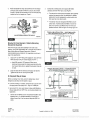
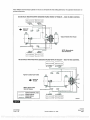
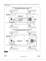
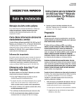
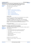
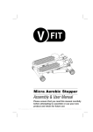
Tank -Mounted
Refer to Figure 2.
ECU /DUAL MODULATOR VALVE MOUNTED WITH
1.
SENSORS FACING FRONT OFTRAILER
(TANK- MOUNTED)
Before beginning the installation procedure, inspect the
modulator valve assembly for damage that may have
occurred during shipping or storage.
ECU /dual
CURBSIDE
Look for crushed or bent connectors.
VE2
Verify that the retainer clips have not been bent or
CURBSIDE
otherwise damaged.
YE1
Do not install a damaged ECU /dual modulator valve
assembly. Notify your supervisor, or contact Meritor WABCO
if there is any apparent damage.
2.
/
ROADSIDE
BU1
ROADSIDE
BU2
Have the following installation material available.
* ECU /dual modulator valve assembly
* ABS relay valve and relay valve extension cable with bayonet
ECU /DUAL MODULATOR VALVE MOUNTED WITH
SENSORS FACING REAR OFTRAILER
connector (3M systems)
* Power cable or power /diagnostic cable
* Sensor extension cables (two pieces for 2S systems, four
pieces for 4S systems)
CURBSIDE
BU2
* Sensors (two or four) for non -ABS prepped axles
CURBSIDE
BU1
* ABS Indicator Label (TP- 95172)
U!!
5/8 -inch O.D. nylon tubing for supply (frame mount)
Pipe plug (3/4 -inch NPTF)
Schedule 80 hex pipe nipple (3/4 -inch NPTF) for air tank
mounts or two Grade 8 bolts (3/8 -inch) and prevailing torque
PLUG UNUSED
PORT
nuts for frame mounts
SAE -standard, DOT- approved thread sealant
To
ROADSIDE
R
YE1
ROADSIDE
VE2
Exhaust port
must face DOWN.
4003548a
ensure correct lamp operation, use an incandescent -type
Figure 2
DOT- approved lamp, or an LED with integral load resistor.
* Meritor WABCO components
TP -20214
Revised 10 -05
Page 2
i
(16579/22882)
Copyright ArvinMeritor, Inc., 2005
Printed
in
USA
PDF compression, OCR, web optimization using a watermarked evaluation copy of CVISION PDFCompressor
A
When mounting the ECU /dual modulator valve assembly to the
WARNING
trailer cross member, refer to SAE specification J447, Prevention of
You must use a Schedule 80 hex nipple (3/4 -inch NPTF) to
ECU /dual
mount the
modulator valve assembly securely to the
air tank to avoid possible serious personal injury and damage
to the component.
Corrosion of Motor Vehicle Body and Chassis Components. Follow
all recommendations and procedures. Your supervisor should have a
copy of this specification.
Install a 3/4 -inch NPTF fitting in the supply port. Use a 3/4 -inch
1.
1.
Use a
3/4 -inch NPTF Schedule 80 hex nipple to attach the
ECU /dual
modulator valve assembly to
a
NPTF pipe plug to plug the unused supply port (Port 1).
reinforced air tank.
Apply SAE -standard, DOT- approved Teflon tape or paste -type
Do not overtighten.
thread sealant to all pipe plugs beyond the first two threads.
Meritor WABCO does not recommend the use of
a vise
when
Pipes with pre -applied thread sealant may also be used.
installing the hex nipple. Use of a vise may cause
Locate a position for mounting the assembly to the vehicle
2.
overclamping. Overclamping may damage the internal
cross member midway between the side rails, close to the
components of the ECU /dual modulator valve assembly.
2.
Use a
brake chambers the valve serves.
3/4 -inch NPTF pipe plug to plug the unused supply port.
Drill two 3/8 -inch mounting holes. The distance between
Apply SAE -standard, DOT- approved Teflon tape or paste -type
the two holes (O.D.) must be 6.06- inches (154 mm) and
thread sealant to all pipe threads beyond the first two threads.
mount directly to the cross member.
Pipes with pre -applied thread sealant may also be used.
3.
until the exhaust port faces DOWN and the connection is
Build a mounting bracket with two 3/8 -inch mounting holes
secure. Use a torque wrench or ratchet with an extension at the
spaced 6.06- inches (154 mm O.D.) apart.
3/4 -inch pipe plug installed on the front supply port.
'
OR
Rotate and tighten the ECU /dual modulator valve assembly
attach the assembly. Tighten the bolts to 18 lb -ft (24 Nm).
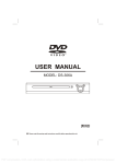
Mounted to Cross Member of Vehicle (Mounting
Bracket Not Supplied)
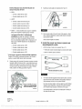
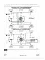
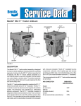
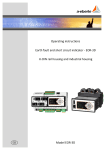
II.
Refer to Figure 3.
ECU /DUAL MODULATOR VALVE MOUNTED
TO A CROSS MEMBER OF THE VEHICLE WITH
SENSORS FACING FRONT OF TRAILER
Exhaust port
must face DOWN.
1-
PLUG ALL
UNUSED PORTS
- -
ROADSIDE
BU2
mount the
l
modulator valve assembly securely to the
to the component.
Use a
3/4 -inch NPTF Schedule 80 hex nipple to attach the
relay valve assembly to a reinforced air tank. Do not
CURBSIDE
overtighten.
VE1
Mentor WABCO does not recommend the use of
overclamping. Overclamping may damage the internal
components of the ECU /dual modulator valve assembly.
2.
PLUG ALL
UNUSED PORTS
when
a vise
installing the hex nipple. Use of a vise may cause
Exhaust port
must face DOWN.
I
ECU /dual
air tank to avoid possible serious personal injury and damage
ECU /DUAL MODULATOR VALVE MOUNTED WITH
SENSORS FACING REAR OF TRAILER
ROADSIDE
YE2
WARNING
You must use a Schedule 80 hex nipple (3/4 -inch NPTF) to
1.
YE2
Attach the ABS external relay valve
(4S /3M systems only).
A
BU1
CURBSIDE
O
Tank -Mounted
ROADSIDE
FRONT OF
TRAILER
Use two 3/8 -inch Grade 8 bolts with prevailing torque nuts to
3.
Use a
3/4 -inch NPTF pipe plug to plug the unused supply port.
Apply SAE -standard, DOT- approved Teflon tape or paste -type
thread sealant to all pipe threads beyond the first two threads.
Pipes with pre -applied thread sealant may also be used.
ROADSIDE
VE1
CURBSIDE
BU1
Figure
CURBSIDE
BU2
FRONT OF
TRAILER
4005403b
3
TP -20214
(16579/22882)
Printed in USA
Revised 10 -05
Copyright ArvinMeritor, Inc., 2005
Page 3
PDF compression, OCR, web optimization using a watermarked evaluation copy of CVISION PDFCompressor
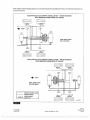
Rotate and tighten the relay valve assembly until the exhaust
3.
port faces down and the connection
is
secure. Use a torque
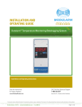
2.
Connect the air delivery lines to the appropriate brake
chambers (3/8 -inch NPT). Figure 5 and Figure 6.
wrench or ratchet with an extension at the 3/4 -inch pipe plug
installed on the front supply port. Figure 4.
The valve portion of the ECU /dual modulator valve assembly
contains two separate valves: one dedicated to roadside
wheel ends, the other dedicated to curbside wheel ends,
Each valve has three delivery ports.
PLUG
UNUSED
The external relay valve designated RED (RD)
PORTS
axle
is an
control valve. It controls brake chambers on one or two
Exhaust
port must
face DOWN.
important that delivery lines from Port
CONTROL
axles.
PORT 4
plumbed as shown. Refer to Figure 13 through Figure 19.
It is
2 are
-
SUPPLY
PORT 1
TYPICAL 2M INSTALLATION
VALVE MOUNTED
WITH SENSORS FACING FRONT OFTRAILER
ABS EXTERNAL MODULATOR VALVE
Il
1002073d
Figure 4
.
1
1
I
1
I
Mounted to Cross Member of Vehicle (Mounting
Bracket Not Supplied)
141--r
:_
-
1
;'
I
I
.
;.
j
-.I
I
-
'
,,.,: I
'1`tI
yv'
I
A
I
When mounting the relay valve assembly to the trailer cross
member, refer to SAE specification J447, Prevention of Corrosion of
I
11
r:5°-------!
I------------
Motor Vehicle Body and Chassis Components. Follow all
recommendations and procedures. Your supervisor should have
-----------
a
copy of this specification.
1.
- - - --
Install a 3/4 -inch NPTF fitting in the supply port. Use a 3/4 -inch
NPTF pipe plug to plug the unused supply port (Port 1).
Apply SAE -standard, DOT- approved Teflon tape or
paste -type thread sealant to all pipe plugs beyond the first
I
SERVICE /CONTROL LINES
SERVICE BRAKE
SUPPLY AIR
SPRING BRAKE AIR
4003550a
Figure 5
two threads. Pipes with pre -applied thread sealant may also
-
be used.
2.
Install the valve with two locknuts and washers as required.
Tighten the hex nuts to 18 lb -ft (24 Nm).
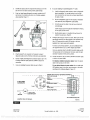
III.
TYPICAL 2M INSTALLATION
VALVE MOUNTED
WITH SENSORS FACING REAR OFTRAILER
-----------------1
-' 'T-------c&-
O
I
Connect the air lines.
Before connecting the air lines, plumb the spring brake relay or
emergency brake relay into the system as usual.
If you are
o
I
i
I
1
1
e a.
1
mounting on a bracket, connect the air supply line from
W
..
i
e
the supply tank to the supply Port 1. Plug the unused port.
1
Use
II
1
I
supply tank.
- - - --
Connect the air delivery lines to the ECU /dual modulator valve
assembly Port 2. For 4S /3M installations, connect the air
delivery lines to Port 2 on the external relay valve (3/8 -inch
NPTF).
.., .
.I
-----------'
I-----------------r
-- -
5/8 -inch O.D. min. nylon tubing or heavy -walled Schedule
80 pipe nipple (3/4 -inch NPTF) if you are mounting directly to the
1.
i
1If
i
Figure
SERVICE /CONTROL LINES
SERVICE BRAKE
SUPPLY AIR
SPRING BRAKE AIR
4003551a
6
TP -20214
Revised 10 -05
Page 4
(16579/22882)
Copyright ArvinMeritor, Inc., 2005
Printed in USA
PDF compression, OCR, web optimization using a watermarked evaluation copy of CVISION PDFCompressor
3.
4.
Connect the brake service (control) line to the ECU /dual
Do not overtighten the tie wraps on a cable. Overtightening can
modulator valve assembly Port
damage the cable. Do not tie wrap the molded sensor plug.
4
(1
/4 -inch NPTF).
The sensor extension cable must follow the brake hose to the
For 4S/3M installations, perform the following procedures.
ECU /dual
A.
Connect the brake service (control) line to the ECU /dual
modulator valve assembly Port
4
modulator valve assembly to allow for axle jounce
and rebound.
(1/4-inch NPTF) and
ABS external relay valve control Port 4 (3/8 -inch NPTF).
4.
Secure the cables every eight inches (203 mm) with tie wraps
or cable clips.
B.
Use an ABS relay valve connection cable to connect the
ECU
/dual modulator valve assembly with the ABS external
5.
assembly
relay valve.
5.
6.
Plug any unused delivery ports.
Push the sensor retainer clip on the ECU /dual modulator valve
UP.
Remove the protective caps from YE2 and YE1 sensor
connectors.
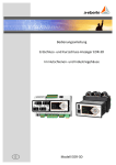
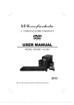
IV.
Install the sensor extension cables
(ABS- prepped axles).
7.
Plug the sensor extension cables into the ECU /dual modulator
valve assembly. To secure the connection, push the sensor
retainer clip DOWN. Retainer clips must fit in the groove of the
Instructions for installing sensors on non -ABS- prepped axles are
included
in
sensor connectors to ensure correct connection.
the Appendix.
ECU /Dual
Meritor WABCO recommends placing sensors on the axle that will
Modulator Valve Assembly Mounted with
Sensors Facing Front of Trailer
provide the most braking performance. The suspension
2S/2M
manufacturer can provide this information.
1.
Visually inspect the tooth wheel and sensor to ensure no
damage occurred during shipping. Perform any necessary
repairs.
-
Connect curbside sensor at YE1.
Connect roadside sensor at BU1.
4S /2M*
2.
Connect the sensors and cables on the prepped axles to the
sensor extension cables. Figure 7.
Ensure that each connection is secure.
Connect curbside front sensor at YE1.
Connect curbside rear sensor at YE2.
Connect roadside front sensor at BU1.
Connect roadside rear sensor at BU2.
4S /3M*
SENSOR
EXTENSION
CABLE
-
Sensor locations vary by type of installation.
Refer to the diagrams on the following pages for specific
sensor locations.
For Enhanced Easy- StopTM 4S /3M lift axle
installations, you must use TOOLBOXTM Software,
SENSOR
AND CABLE
version 4.6 or higher, to enable the lift axle function.
It is not
automatically enabled. Refer to Enabling the Lift
Axle Function (4S/3M Installations) in the Appendix for
instructions.
4003567b
Figure
'
3.
7
Route the sensor cable along the back side of the trailer axle to
the ECU /dual modulator valve assembly. Route the cable with
the brake hose.
-
Connect curbside sensor at YE1.
Connect curbside sensor at YE2.
Connect roadside sensor at BU1.
Connect roadside sensor at BU2.
* If the lift axle is sensed in 4S /2M and 4S /3M installations:
Sensors YE2 and BU2 must always be used on the lift axle to
avoid an unwanted ABS indicator lamp illumination.
TP -20214
(16579/22882)
Printed in USA
Revised 10 -05
Copyright ArvinMeritor, Inc., 2005
Page 5
PDF compression, OCR, web optimization using a watermarked evaluation copy of CVISION PDFCompressor
3.
4.
Connect the brake service (control) line to the ECU /dual
Do not overtighten the tie wraps on a cable. Overtightening can
modulator valve assembly Port 4 (1/4 -inch NPTF).
damage the cable. Do not tie wrap the molded sensor plug.
The sensor extension cable must follow the brake hose to the
For 4S /3M installations, perform the following procedures.
ECU /dual
A.
Connect the brake service (control) line to the ECU /dual
modulator valve assembly Port
4
modulator valve assembly to allow for axle jounce
and rebound.
(1/4-inch NPTF) and
ABS external relay valve control Port 4 (3/8 -inch NPTF).
4.
Secure the cables every eight inches (203 mm) with tie wraps
or cable clips.
B.
Use an ABS relay valve connection cable to connect the
ECU /dual
modulator valve assembly with the ABS external
5.
assembly
relay valve.
5.
6.
Plug any unused delivery ports.
Push the sensor retainer clip on the ECU /dual modulator valve
UP.
Remove the protective caps from YE2 and YE1 sensor
connectors.
IV.
Install the sensor extension cables
(ABS- prepped axles).
7.
Plug the sensor extension cables into the ECU /dual modulator
valve assembly. To secure the connection, push the sensor
retainer clip DOWN. Retainer clips must fit
Instructions for installing sensors on non -ABS- prepped axles are
included in the Appendix.
Meritor WABCO recommends placing sensors on the axle that will
provide the most braking performance. The suspension
the groove of the
ECU /Dual
Modulator Valve Assembly Mounted with
Sensors Facing Front of Trailer
2S /2M
manufacturer can provide this information.
1.
in
sensor connectors to ensure correct connection.
Visually inspect the tooth wheel and sensor to ensure no
damage occurred during shipping. Perform any necessary
repairs.
-
Connect curbside sensor at YE1.
Connect roadside sensor at BU1.
4S /2M*
2.
Connect the sensors and cables on the prepped axles to the
sensor extension cables. Figure 7.
Ensure that each connection is secure.
Connect curbside front sensor at YE1.
Connect curbside rear sensor at YE2.
Connect roadside front sensor at BU1.
Connect roadside rear sensor at BU2,
4S/3M*
-
Sensor locations vary by type of installation.
Refer to the diagrams on the following pages for specific
sensor locations.
For Enhanced Easy- StopTM 4S /3M
lift axle
installations, you must use TOOLBOXTM Software,
version 4.6 or higher, to enable the lift axle function.
It is
not automatically enabled. Refer to Enabling the Lift
Axle Function (4S /3M Installations) in the Appendix for
instructions.
Figure
3.
7
Route the sensor cable along the back side of the trailer axle to
the ECU /dual modulator valve assembly. Route the cable with
the brake hose.
-
Connect curbside sensor at YE1.
Connect curbside sensor at YE2.
Connect roadside sensor at BU1.
Connect roadside sensor at BU2.
* If the lift axle is sensed in 4S /2M and 4S /3M installations:
Sensors YE2 and BU2 must always be used on the lift axle to
avoid an unwanted ABS indicator lamp illumination.
TP -20214
(16579/22882)
Printed in USA
Revised 10 -05
Copyright ArvinMeritor, Inc., 2005
Page 5
PDF compression, OCR, web optimization using a watermarked evaluation copy of CVISION PDFCompressor
ECU /Dual
Modulator Valve Assembly Mounted with
9.
Bundle any excess cable in a loop (bow tie). Figure 9.
Sensors Facing Rear of Trailer
2S /2M
-
Connect curbside sensor at BU1.
Connect roadside sensor at YE1.
4S /2M*
Connect curbside front sensor at BU1.
Connect curbside rear sensor at BU2.
Connect roadside front sensor at YE1.
Connect roadside rear sensor at YE2.
4S/3M*
-
Figure 9
Sensor locations vary by type of installation.
Refer to the diagrams for specific sensor locations.
10. Secure excess cable
For Enhanced Easy- StopTM 4S /3M lift axle
in
the sub -frame of the vehicle or along
the air hoses as appropriate. Excess cable should not exceed
installations, you must use TOOLBOXTM Software,
two feet (0.61 meter).
version 4.6 or higher, to enable the lift axle function.
It is
Various cable lengths are available.
not automatically enabled. Refer to Enabling the Lift
Axle Function (4S/3M Installations) in the Appendix for
V.
instructions.
-
Connect curbside sensor at BU1.
1.
Connect curbside sensor at BU2.
Install the power and lamp or power and
lamp /diagnostic cable.
Identify the type of cable to be installed. Figure 10.
Connect roadside sensor at YE1.
ABS trailer industry- standard pigtail connector power cable
Connect roadside sensor at YE2.
Blunt -cut power cable (not shown)
* If the lift axle is sensed in 4S /2M and 4S /3M installations:
Sensors YE2 and BU2 must always be used on the lift axle to
avoid an unwanted ABS indicator lamp illumination.
8.
Create a strain relief to protect the sensor extension connector
terminals. Without this strain relief, normal trailer jounce and
vibration will cause the terminals to spread and loosen. Use a
tie wrap or clip to secure the cable to the brake air delivery
hose as close to the fitting as possible. Figure 8.
Figure 10
2.
For industry- standard pigtail connector power cables, route the
cable from the harness connector to the ECU /dual modulator
valve assembly and secure it to prevent damage.
Attach individual sensor
cables to corresponding
brake air delivery hoses.
For blunt -cut power cables, route the cable from the ECU /dual
modulator valve assembly to
a
junction box which interfaces
with the seven -way connector at the front of the trailer.
4005457b
Leave enough slack in the cable to compensate for flexing of
Figure
8
the trailer and sub -frame.
TP -20214
Revised 10 -05
Page 6
(16579/22882)
Copyright ArvinMeritor, Inc., 2005
Printed in USA
PDF compression, OCR, web optimization using a watermarked evaluation copy of CVISION PDFCompressor
3.
Bundle any excess cable in a loop (bow tie) and secure it in the
8.
sub -frame of the trailer body to prevent cable damage.
4.
If
you are installing the power /diagnostic "Y" cable:
Install the diagnostic cable bracket so that the diagnostic
A.
Push the hinged power /diagnostic connector retainer clip UP
plug is accessible. The normal location is on the right
and remove the protective cap from the ECU /dual modulator
front corner of the sub -frame, but will vary depending on
valve assembly. Figure 11.
the type of trailer.
Route the diagnostic cable from the ECU /dual modulator
B.
valve assembly to the diagnostic cable bracket.
-4- -
l'
CAP
Correctly secure the cable in the sub -frame to prevent
C.
cable damage.
KEYED CABLE
Leave enough slack in the cable to compensate for flexing
CONNECTOR
of the trailer and sub -frame.
Bundle excess cable in a loop (bow tie) and secure the
D.
cable
9.
in
the sub -frame. Figure 9.
Install the ABS indicator lamp on the trailer. Refer to the vehicle
specification sheet for the exact location of the indicator lamp.
MATING
TRAILER
HARNESS
CONNECTOR
Use a DOT- approved lamp with ABS etched on the lens
(available from major trailer parts suppliers).
To
4003569a
Figure
ensure correct lamp operation, use an incandescent -type
DOT- approved lamp or an LED with integral load resistor.
If
11
you are using the industry- standard connector cable and do
not have access to the mating trailer harness, mask the open
5.
connector to protect it from paint or grease.
Plug the power 8 -pin connector on the power or power/
diagnostic cable into the ECU /dual modulator valve assembly.
6.
10.
Pull the hinged power/diagnostic connector retainer clip on the
ECU /dual
For industry- standard connector cables: Attach the power
modulator valve assembly DOWN to secure the
connection.
7.
Connect the power. Use the industry- standard connector cable
or a blunt -cut power cable.
If you
cable to the harness on the trailer.
are installing the power cable only, go to Step 9.
For an optional blunt -cut power cable: Wire the cable and
ABS indicator lamp to the seven -way connector on the trailer
according to the following diagram. Figure 12.
GENERIC INPUT /OUTPUT (EXPANDED CAPABILITY)
WHITE AND YELLOW
WHITE
WHT
4 OR 5 WIRE
BLK
SCHEMATIC
7
WAY
o
BLU
o
BRN
o
GRN
L
RO
(GROUND)
o'
1
BLUE
(CONSTANT POWER)
:#1
RED
(STOP LAMP)
GREEN AND WHITE
(
1
r77
GROUND
C
TRAILER ABS
INDICATOR LAMP
ECU POWER CONNECTOR
Junction box not shown.
4003570a
Figure 12
TP -20214
(16579/22882)
Printed in USA
Revised 10 -05
Copyright ArvinMeritor, Inc., 2005
Page 7
PDF compression, OCR, web optimization using a watermarked evaluation copy of CVISION PDFCompressor
Typical Easy- StopTM Trailer ABS Installations
Refer to Figure 13 through Figure 19 for typical Easy- StopTM trailer ABS installations.
Mentor WABCO recommends placing sensors on the axle that will provide the most braking performance. The suspension manufacturer can
provide this information.
== ==j
YE
2S /2M VALVE MOUNTED WITH SENSORS
FACING FRONT OFTRAILER
SIDE -TO -SIDE CONTROL
-
I
4. TRAILER
FRONT OF
W
- -,
!Ì
YE
o
.
BU1
NOTE: Spring brake
lines not shown.
rTh
fTk-
1
------
I
I
,
==
¡_ ==
=_=
==
BU7
-----J
M. WO
l
2S /2M VALVE MOUNTED WITH SENSORS
FACING REAR OFTRAILER
SIDE -TO -SIDE CONTROL
-
aut
411.
FRONT OF
TRAILER
114--
- - - - -__
-__-_-_-_-_-_-_-_--_-_-_-_-_
_____________ -I
I:6I
-d
W
I
1
I
I
II
euB
o
ri' iir
BU1
o
IÌ
ii
YE1
II
YE2
I
----------------------------------I
1
131
===
C-=
r--- _`
__-
NOTE: Spring brake
1
lines not shown.
YE1
SERVICE /CONTROL LINES
-- - - -
SENSOR CABLES
SERVICE BRAKE
SUPPLY AIR
40035543
Figure 13
TP
-20214
Revised 10
Page 8
-05
(16579/22882)
Copyright ArvinMeritor, Inc., 2005
Printed in USA
PDF compression, OCR, web optimization using a watermarked evaluation copy of CVISION PDFCompressor
Meritor WABCO recommends placing sensors on the axle that will provide the most braking performance. The suspension manufacturer can
provide this information.
4S /2M VALVE MOUNTED WITH SENSORS FACING FRONT OFTRAILER
I___
YE1
I
y
- SIDE -TO -SIDE CONTROL
lllllllllll
/11111/11
YE2
..
f
FRONT OF
TRAILER
Ii'r
Typical Tandem Axle Trailer
o
rlñ
¡-
---------- -----
1
=.=
=7_3 ==
BU1
;
NOTE: Spring brake
BU2
'
lines not shown.
1
4S /2M VALVE MOUNTED WITH SENSORS FACING REAR OFTRAILER
- SIDE -TO-SIDE CONTROL
7- = =
r---
_-
BU1
I]
BU2
4
t
C
Typical Tandem Axle Trailer
4.
FRONT OF
TRAILER
BU2
Ij
BU1
O
YE1
NOTE: Spring brake
S'itirOr
700-
lines not shown.
YE2
fTP-
l--
SERVICE /CONTROL LINES
-----
SENSOR CABLES
YE1
SERVICE BRAKE
SUPPLY AIR
L__
==
__=_
YE2 ÍJ.LI.L1.Ll.0
4003555a
Figure 14
TP
(16579/22882)
Printed in USA
-20214
Revised 10 -05
Copyright ArvinMeritor, Inc., 2005
Page 9
PDF compression, OCR, web optimization using a watermarked evaluation copy of CVISION PDFCompressor
Mentor WABCO recommends placing sensors on the axle that will provide the most braking performance. The suspension manufacturer can
provide this information.
-
4S /2MTYPICALTRI -AXLE
VALVE MOUNTED WITH SENSORS
FACING FRONT OFTRAILER
SIDE -TO -SIDE CONTROL
=:_=
=-=
-
=__=
L_
-=
L_
YE2
YE1
FRONT OF
TRAILER
r
------r
I
I
)
-..
--ri
O
9F.
4411.
--
__
nnnu
C
I
II
YE2
..
NOTE: Spring brake
YE1
lines not shown.
o
But
;71}
BU2
'
II
1-,
DIY
BU1
---------------
J4
D:W
C1=03
)
===
L
Anta
'
_C
L _J
_
-
4S /2MTYPICALTRI -AXLE
VALVE MOUNTED WITH SENSORS
FACING REAR OFTRAILER
SIDE -TO -SIDE CONTROL
-=
C==J
L_ -
=0;0
77=
C===
C
C;=)
BU2
BU1
D:W
tI
I.
I
+.....
Dt
I-
FRONT OF
TRAILER
)
J, r---
r
--------I
III
NOTE: Spring brake
lines not shown.
BU2
o
BU7
'«I[
SERVICE /CONTROL LINES
YE1
YE2
-- ---
SENSOR CABLES
SERVICE BRAKE
SUPPLY AIR
JJL----1
I
CCFYE1
__
L__J
J
C=á-=
L_
E6-
L _J
4003556a
Figure 15
TP -20214
(16579/22882)
Revised 10 -05
Page 10
Copyright ArvinMeritor, Inc., 2005
Printed in USA
PDF compression, OCR, web optimization using a watermarked evaluation copy of CVISION PDFCompressor
Meritor WABCO recommends placing sensors on the axle that will provide the most braking performance. The suspension manufacturer can
provide this information.
-
4S /2M TYPICAL AXLE CONTROL INSTALLATION
VALVE MOUNTED
WITH SENSORS FACING FRONT OFTRAILER
--
L
L_.____J
=1;13
BU1
111/
L_
IIIIIIIII
.._
VE7
FRONT
YE2
o
o
NOTE: Spring brake
lines not shown.
1=6-
TIPYE2
MUMS
®82 I
C
=_ _
)
-
4S /2M TYPICAL AXLE CONTROL INSTALLATION
VALVE MOUNTED
WITH SENSORS FACING REAR OFTRAILER
CT=
)
IIUIIIII
BU1
YE1
Q.
s
'
LJ.I
BU2
ION
FRONT
.i'nr
o
o
NOTE: Spring brake
lines not shown.
YE2
1--
i
SERVICE /CONTROL LINES
SENSOR CABLES
BU2
SERVICE BRAKE
YE2
Iluunl
SUPPLY AIR
L____J
4002773a
Figure 16
TP -20214
(16579/22882)
Printed in USA
Revised 10 -05
Copyright ArvinMeritor, Inc., 2005
Page 11
PDF compression, OCR, web optimization using a watermarked evaluation copy of CVISION PDFCompressor
NOTE: For Enhanced Easy- StopTM 4S /3M
lift axle installations,
you must use TOOLBOXTM Software, version 4.6 or higher, to enable the
lift axle function. It is not automatically enabled. Refer to Enabling the Lift Axle Function (4S /3M Installations) in the Appendix for instructions.
Meritor WABCO recommends placing sensors on the axle that will provide the most braking performance. The suspension manufacturer can
provide this information.
4S
==
L__=J
I
I'
Q
1
)
Q
I----
I
.
I
y
===
YE1
YEI
FRONT OF
TRAILER
-
-AXLE WITH FRONT LIFT
VALVE MOUNTED
WITH SENSORS FACING FRONT OFTRAILER
I
YE2
YE1
o
'r""
o
',c1,f:
BU1
Ll
BU2
ee
--------------
I
BU2
-
NOTE: Spring brake
BUi
Le__J
1--,
lines not shown
77_
C==C
J
-
4S /3MTYPICALTRI -AXLE WITH FRONT LIFT
VALVE MOUNTED
WITH SENSORS FACING REAR OFTRAILER
==
=PPP=
=L.=
:=
C
__
=
BU2
BU1
4
sr
4.
- -I
FRONT OF
TRAILER
==-7
-
r
+....
1--------s--------7 i
I
L
1
W
SERVICE /CONTROL LINES
I
o
- 1711
I
t,,i
- - - --
SENSOR CABLES
I
l
,_,
BU2
BU1
SERVICE BRAKE
SUPPLY AIR
rl
YE1
I
Á1
YE2
NOTE: Spring brake
l
lines not shown.
1
_J
r- 1g
YEI
1
=
===
LLF
YEl
lllll 1111
C=_
r
C--=
4003557a
Figure 17
TP -20214
Revised 10 -05
Page 12
(16579/22882)
Copyright ArvinMeritor, Inc., 2005
Printed in USA
PDF compression, OCR, web optimization using a watermarked evaluation copy of CVISION PDFCompressor
Meritor WABCO recommends placing sensors on the axle that will provide the most braking performance. The suspension manufacturer can
provide this information.
4S /3MTYPICALTRI -AXLE
==
-- -
- VALVE MOUNTED WITH SENSORS FACING FRONT OFTRAILER
---
L---
L,--_
0=0:1
YE1 .....
YE2
V.4
S
FRONT OF
TRAILER
I
I
_
o
o
.
I
o
±
1=r1
4
-------- ¡- ------- I
1
NOTE: Spring brake
o
o
E2
o
YE1
SERVICE /CONTROL LINES
Typical Tandem
Axle Trailer
I
I
lines not shown.
.
---- -
But
BU2
SENSOR CABLES
SERVICE BRAKE
SUPPLY AIR
1
1
-1-----------------L
I10-
==
==
BU2
4S /3MTYPICALTRI -AXLE
Buz
-d-
S
40.
FRONT OF
TRAILER
I
BU1
.J
I
- VALVE MOUNTED WITH SENSORS FACING REAR OFTRAILER
==
7-7
r-
L____a._J
C®R=
G®
®
==
==
==
11111111111
¢Q
BUt
D?I
I
II
O
13
1
BU2
I
1,
o
r2
Typical Tandem
Axle Trailer
!IA
I IIII4J
I
o
nI
Il
YE1
LIT
Sf
.EI
L
YE2
Imo,
I
=rJ¡
.,1'
YJ
L_l.-
_
NOTE: Spring brake
lines not shown.
-
BU1
i
Em-
=:=
==
YE1
___J
4003558a
Figure 18
TP -20214
(16579/22882)
Printed in USA
Revised 10 -05
Copyright ArvinMeritor, Inc., 2005
Page 13
PDF compression, OCR, web optimization using a watermarked evaluation copy of CVISION PDFCompressor
Meritor WABCO recommends placing sensors on the axle that will provide the most braking performance. The suspension manufacturer can
provide this information.
-
4S /3M TYPICAL FOUR AXLE PULLTRAILER
VALVE MOUNTED
WITH SENSORS FACING FRONT OFTRAILER
=1C
=C
CIC C==C
C__C C=_C
111111111
YE2
--I
¢
S
114.
FRONT OF
TRAILER
T
i
1rI
1
1
I
NOTE: Spring brake
lines not shown.
la.
i
-
YE2
It
I
1
I
o
4
___
I
SERVICE /CONTROL LINES
- - - --
SENSOR CABLES
SERVICE BRAKE
SUPPLY AIR
81.12
II
I_ J
I
i1
.
Le __A__
E6Bata,
B US
=
T___D
IN. NO
L______)
-
4S /3M TYPICAL FOUR AXLE PULLTRAILER
VALVE MOUNTED
WITH SENSORS FACING REAR OF TRAILER
=_=
COI=
=== L.:7r=
=
C__
FRONT OF
TRAILER
BU7
¢
+
0,*
S?
11
la
o
`
I1>U$ID
BU2
II-I
ÌI
I
4
a
I
W
11
n
BUS
r
g
NOTE: Spring brake
lines not shown.
C
...
A1
BU7-
I.
Á
o
YrS
r
-- -I
l.F
I
1:3!
==
=C ==e7
YE2
YE1
C==C C==C
C==C C==C
¡¡
11
L__
4003559a
Figure 19
TP
-20214
Revised 10 -05
Page 14
(16579/22882)
Copyright ArvinMeritor, Inc., 2005
Printed in USA
PDF compression, OCR, web optimization using a watermarked evaluation copy of CVISION PDFCompressor
End of Line Testing
I(
It Mentor WADCO
rr
installations. To run these tests, Meritor WABCO recommends you
use TOOLBOXTM Software.
ECU
own
Tresin ADS Dnaannstscs
gads, ÇanponereTesh NOON deb
Teak. ECU
End of line testing is required on all Enhanced Easy- StopTM
"i, ritSq A0I
tnte, euon
ro#.lrs
Marwiactue Date
TOOLBOXTM Software and general test procedures are included in
ECU Type
this bulletin.
Cabala,
45/111
Sed Mambo
Pact Wade.
446ICECCO1
Scene* Review.
If
you are using a Pro -Link, refer to the operating
manual for test instructions.
I
-
bream
Ecy
I
Voted
hS
),;r.,
B::.r
Voltages
'
AMITYY
you are testing an installation that has a power only cable,
temporarily install
a
t
YE2
(.
SWUM
Ivan
BONI
=^aÌ
-
FT-
EU1
7
I
1
r7"--
eU2
Saurian InfaacMìron
.
.1
¡1;,
]
109+2000
I
Curer* Mint
lci
Sera We:
p
Revs/Mb
495
I
World
13 G6i
rJ
I1
Meritor WABCO combination power /diagnostics
Menage Center'
"Y" style cable.
1.
,
II
YE1
13 G6;
Secondary
If
-
r
i
Wheel Sena
Kr
Fault.
Enhanced Easy- StopTM 2S /2M, 4S /2M and
4S /3M Premium Installation
End of Line
Testing Procedure with TOOLBOXTM
Software
i
Connect the diagnostic connector on the cable to the PC serial
port/SAE diagnostic interface (J1587/J1708 to RS232
interface).
-
'
.
4003560a
Figure 20
Refer to the Software Owner's Manual, TP- 99102, for
instructions for running TOOLBOXTM Software.
2.
Display the Trailer ABS Main Screen.
3.
Verify the power supply.
Check the Faults field on the Main Screen,
4.
NONE = No faults present, proceed with end of line test.
YES = Faults present, double -click on "YES" to bring up the
Apply 12 volts DC to the blue wire (constant). Check the
fault information screen.
screen for the correct voltage (9.5 to 14 volts). Constant
power voltage
is
Use the information in the
displayed in the PRIMARY field. Figure 20.
Repair Instructions field
to perform
the necessary repairs. Figure 21.
Apply 12 volts DC to the red wire (stoplight power). Check
the screen for the correct voltage (9.5 to 14 volts). Stoplight
power voltage
is
displayed
in the SECONDARY
field.
c
Figure 20.
The internal field is not applicable to this test.
t AAA
rda,...d,n
la]
lases
r
UI
trau:
IaillEMEINIEMIMH'KA1110
mII
11® ..,.... ......,o...
Rawl
J
j
twMro411oaY
llY..p.-'.V
rear awes C.i.': s.,+-:u..vr.y+t:,eUav *Weep d'.,a
Pula ea.a.ea.x.e
*NO to
^.lFJc.V..l.',(:
1
çlaors
I(
_f
Qw resh
1
+
Dirt
(
S.,.
I
eel
I
4003561a
Figure 21
TP
(16579/22882)
Printed in USA
-20214
Revised 10 -05
Copyright ArvinMeritor, Inc., 2005
Page 15
PDF compression, OCR, web optimization using a watermarked evaluation copy of CVISION PDFCompressor
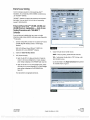
End of Line Test with TOOLBOXTM Software
7.
Verify Correct Valve and Lamp Installation
To
verify valve and lamp installations with TOOLBOXTM Software:
1.
Apply 12 volts DC to the ABS.
2.
Apply air to the emergency line to fill the air tanks and release
Repeat this test for the Blue valve.
A.
Repeat Steps
B.
Select the Blue valve from the valve activation screen.
C.
Click on the Activate button to verify correct valve
1
-3.
installation (Blue).
D.
the spring brakes.
Check for correct air line installation. To accomplish this,
observe the slack adjusters.
3.
Apply air to the control line.
4.
At the Trailer Main Screen, click on Component Test, then
adjusters will move in and out as the ROADSIDE
select Valves/Lamp to display the Valve Activation Screen.
portion of the dual modulator valve cycles. If this does
The Yellow valve indicator will be highlighted. Figure 22.
not happen, the air lines are not correctly connected.
If
the ECU faces the FRONT of the trailer, the slack
Perform the necessary repairs.
: Valve Activation
the ECU faces the REAR of the trailer, the slack
Select Valve to Activate
adjusters will move
r.
portion of the dual modulator valve cycles.
r
r
r
Yellow
in
and out as the CURBSIDE
If
this does
not happen, the air lines are not correctly connected.
Skie
Actnate
Perform the necessary repairs.
(
Red
8.
AI Wives
r
Test Warning Lamp
,
If
111
--
For 4S /3M installations: Repeat this test for the red valve.
Red: The external relay valve designated RED (RD) is an axle
-
control valve.
Warning Lamp
lest
II
It is
It
controls brake chambers on one or two axles.
important that delivery lines from Port
2 are
plumbed as
shown on the installation drawings. The 4S/3M system is
Test Status
designed to be used with a variety of trailer configurations. Call
ArvinMeritor's Customer Service Center at 800 -535 -5560 for
additional information.
9.
40035620
Click on the Test button to activate the ABS indicator lamp
this
Figure 22
is
-
the lamp that is mounted on the side of the trailer. The
lamp will flash eight times, indicating lamp installation
is OK.
The Test Status box at the bottom of the menu will display the
5.
Click on the Activate button.
6.
Check for correct air line installation. To accomplish this,
status of this test. Figure 22.
10.
Click on Close to exit.
observe the slack adjusters.
Sensor Orientation Test
If
the ECU faces the FRONT of the trailer, the slack adjusters
will move in and out as the CURBSIDE portion of the dual
modulator valve cycles.
If
this does not happen, the air lines
are not correctly connected. Perform the necessary repairs.
If
the ECU faces the REAR of the trailer, the slack adjusters
This test is not for use on 4S/3M installations.
For 4S /3M
installations, use the standard Sensor Test.
To run the
standard test, select Sensor Test from the Components Test
Menu.
will move in and out as the ROADSIDE portion of the dual
The sensor orientation test must be performed as part of the end of
modulator valve cycles.
line testing procedure.
If
this does not happen, the air lines
are not correctly connected. Perform the necessary repairs.
The Test Status box at the bottom of the menu will display the
status of this test.
TP -20214
Revised 10 -05
Page 16
(16579/22882)
Copyright ArvinMeritor, Inc., 2005
Printed in USA
PDF compression, OCR, web optimization using a watermarked evaluation copy of CVISION PDFCompressor
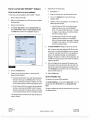
Sensor Orientation Test Screen
01 ICS I1 Sensor
Before beginning this test, look at the ECU to see if the sensors face
Orientation Test
the front or rear of the trailer. TOOLBOXTM will ask for this
information to start the test (Step 5). To perform the sensor
orientation test:
Mlle 400
1.
Raise the sensed wheel ends off the ground.
2.
Apply air to the emergency line to fill the air tanks and release
X
...
Warning Message: This test demands that the wheels be spun in a
predetermined order and that the ECU mounting orientation is
entered by the operator. It is applicable to the following TCS2
configurations only:
2S/1M
25/2M
2S/2M
46/2M
500 101
500 104
500 102
500 103
400
400
400
400
Ut
0
0
0
500 103 0
1
the spring brakes so that the wheels can be rotated.
t
0
Sensors Facing
2
r
r Peer
Front
Sensors
3.
Apply 12 volts DC to the ABS.
4.
At the Trailer Main Menu, click on Component Test, then
Max RPM
But
B a
A wo
Bue
select Sensor Orientation Test to display the Sensor
YE1
Orientation Test screen. Figure 23.
-
OMB
When the Sensor Orientation Test screen first appears, the
Sensors Facing field will display the default
YE2
Front. This
4
will occur regardless of the actual sensor orientation of the
installation being tested.
S
!3
YE1
<7
YE2
<7
But
<7
BU2
E
J
E
E
E
<7
sign
Order
J
Close
4005514a
SP
Figure 24
J
sein outstation ism
Warning Message: This test demands that the wheels be spun in a
predetermined order and that the ECU mounting orientation is
entered by the operator. It is applicable to the following TCS2
configurations only
ICs 11
2S/1 M 400
2S/1M 400
2S/2M 400
2S/2M 400
4812M 400
1
500
500
500
500
500
NOTE: 2S/2M installations use YE1 and BU1 locations.
Sensors Facing
front
Rear
2
Vas_
Click on
6.
101 0
104 0
102 0
103 0
103 0
r
r
-
ml
¡YEi
BU1
_
frE2
YeI
Ye]
BU2
A
B
S
YE1
<7
BUt
F-7
BU2
t7
r
Front
(
rgp
'
3
NMI NIB
YE1
Bu1
Max RPM
YE1
BU2
A
B
S
YE2
BU1
Front or Rear in
the Sensors Facing field to select
411111113
assembly. Figure 24.
Order
p- E
r
rrr- pr
_ ÿ
E2
C Rear
Sensors
But
the mounting orientation of the ECU /dual modulator valve
.
I
WWI
__
4005459a
Refer to Figure 23 and Figure 24 for illustrations of the
ECU
Sensors Facing
2
Figure 23
I
as shown on the diagram...
1
4005458a
Click on
1
Order
......_oore
5.
x
r
YE2
sign
Intl Sensor orientation Test
Spin tire number
Max RPM
<7
begin the test. Figure 25.
-Sensor Orientation Test-
- Sensors
1
Start to
Figure 25
mounted with sensors facing forward and rear. The
correct mounting orientation must be selected prior to starting
the test (Step 5).
TP -20214
(16579/22882)
Printed in USA
Revised 10 -05
Copyright ArvinMeritor, Inc., 2005
Page 17
PDF compression, OCR, web optimization using a watermarked evaluation copy of CVISION PDFCompressor
7.
4S /3M*
sensed wheel end at a rate of 1/2 revolution per second. This
Refer to the diagrams for specific sensor locations.
rate equals a wheel speed of approximately 4 mph (7 kph).
lift axle
installations, you must use TOOLBOXTM Software,
identification block on the screen for results. Sensor
version 4.6 or higher, to enable the lift axle function.
identification boxes are located in the bottom left portion of the
Axle Function (4S /3M Installations) in the Appendix for
Green background: Correct sensor location. Spin the next
instructions.
-
sensed wheel as indicated by the screen prompt.
If
you get a red
background, you must stop the test (click on stop), make the
necessary corrections and repeat Steps 3 through 6.
finish the Sensor Orientation Test, click on Stop, then on
To
Close.
9.
a
Connect curbside sensor at YE2.
Connect roadside sensor at BU1.
Connect roadside sensor at BU2.
tone ring has been installed and that the sensor is
necessary repairs and repeat the test.
If
2S/2M
-
the problem persists,
contact Meritor WABCO (800- 535 -5560). Sensor output
appears in the Sensors field located
in
Modulator Valve Assembly Mounted with
Sensors Facing Rear of Trailer
pushed all the way in against the tone ring. Perform the
the bottom right portion
Connect curbside sensor at BU1.
Connect roadside sensor at YE1.
4S/2M*
of the Sensor Orientation Test screen. Figure 24.
End of Line Testing without TOOLBOXTM
Software
Sensor Installation
1.
Connect curbside sensor at YE1.
ECU /Dual
Verify there is sensor output. If there is no sensor output, verify
that
not automatically enabled. Refer to Enabling the Lift
It is
Sensor Orientation Test screen. Figure 24.
Red background: Incorrect sensor location.
Sensor locations vary by type of installation.
For Enhanced Easy- StopTM 4S /3M
As each sensed wheel is rotated, check the color of the sensor
8.
-
Follow the screen prompts, starting with 1, to rotate each
Look at the sensor connectors on the ECU /dual modulator valve
Connect curbside front sensor at BU1.
Connect curbside rear sensor at BU2.
Connect roadside front sensor at YE1.
Connect roadside rear sensor at YE2.
-
assembly. Ensure that the connectors are routed to the correct
4S /3M*
wheel-end location, as follows:
Refer to the diagrams for specific sensor locations.
ECU /Dual
For Enhanced Easy- StopTM 4S /3M lift axle
Modulator Valve Assembly Mounted with
Sensors Facing Front of Trailer
Sensor locations vary by type of installation.
installations, you must use TOOLBOXTM Software,
version 4.6 or higher, to enable the lift axle function.
2S /2M
I
-
not automatically enabled. Refer to Enabling the Lift
It is
Axle Function (4S/3M Installations) in the Appendix for
Connect curbside sensor at YE1.
instructions.
-
Connect roadside sensor at BU1.
4S /2M*
Connect curbside front sensor at YE1.
Connect curbside rear sensor at YE2.
Connect roadside front sensor at BU1.
Connect roadside rear sensor at BU2.
Connect curbside sensor at BU1.
Connect curbside sensor at BU2.
Connect roadside sensor at YE1.
Connect roadside sensor at YE2.
* If the lift axle is sensed in 4S /2M and 4S /3M installations:
Sensors YE2 and BU2 must always be used on the lift axle to
avoid an unwanted ABS indicator lamp illumination.
2.
If
sensors are not correctly installed, perform the necessary
repairs.
TP -20214
Revised 10 -05
Page 18
(16579/22882)
Copyright ArvinMeritor, Inc., 2005
Printed in USA
PDF compression, OCR, web optimization using a watermarked evaluation copy of CVISION PDFCompressor
Air Line Installation
'
'
1.
2.
3.
For 4S /3M installations: Repeat this test for the red valve.
Ensure that all unused air ports are plugged and that the
Red: The external relay valve designated RED (RD) is an axle
exhaust port
control valve.
is
facing DOWN.
axles. It is
Look at the air line installation to verify that all air lines are
It
controls the brake chambers on one or two
important that delivery lines from Port
plumbed
2 are
as shown in Figure 17, Figure 18 and Figure 19. The
correctly installed.
4S/3M
system is designed to be used with a variety of trailer
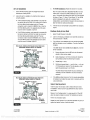
If
the ECU /dual modulator valve assembly is mounted with
configurations. Call ArvinMeritor's Customer Service Center at
the sensors facing the FRONT of the trailer, the air lines for
800 -535 -5560 for additional information.
the three delivery ports located under the YE sensor
connectors must be routed to CURBSIDE; the air lines for
4.
If
the air lines are not correctly routed, perform the necessary
repairs.
the three delivery ports on the opposite side of the valve
must be routed to roadside. Figure 26.
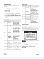
If
the ECU /dual modulator valve assembly
is
mounted with
the sensors facing the REAR of the trailer, the air lines for
the three delivery ports located under the YE sensor
connectors must be routed to ROADSIDE; the air lines for
the three delivery ports on the opposite side of the valve
must be routed to curbside. Figure 27.
Perform End of Line Test
1.
Apply 12 volts DC power to the ABS.
2.
Listen for the ECU /dual modulator valve assembly to click four
times (six times for
3.
If the
indicator lamp comes on for three seconds then goes
out, this indicates
` ']
I[ó
l!
SENSORS FACING FRONT OFTRAILER
YE1
If
/i=I
L
O-O
CURBSIDE
the ABS indicator lamp comes on and stays on, check the
BU1
- ROADSIDE
BU2
`r/r
,1`=i'9''.,y_u
Il
YE
DELIVERY
correct installation. The end of line test is
sensor installation.
CURBSIDE ROADSIDE
YE2
a
complete.
ECU /DUAL MODULATOR VALVE MOUNTED WITH
CURBSIDE
a 4S/3M).
A.
Remove the power from the ABS and raise the sensed
wheels so they may be rotated.
B.
Apply emergency air to fill the air tanks and release the
spring brakes so that the wheels may be rotated.
PLUG ALL
UNUSED
PORTS
C.
Repeat Steps
D.
Rotate each sensed wheel
1
and 2.
-
one at a time
-
at a rate
of 1/2 revolution per second. This rate equals a wheel
BU
DELIVERY
ROADSIDE
speed of approximately 4 mph (7 kph).
4003564a
The ABS indicator lamp should now go out and stay out
Figure 26
indicating a correct installation. The end of line test is
complete.
I^
ECU /DUAL MODULATOR VALVE MOUTED WITH
SENSORS FACING REAR OFTRAILER
ROADSIDE
YE2
Cs
YE
DELIVERY
ROADSIDE
VA.
i
BU1
CURBSIDE
BU2
.419
iV
O
GLlt,-
L7
If
the ABS lamp does not go out, there is a sensor gap problem
or hardware fault. Adjust the sensor and, if necessary, perform
a
ROADSIDE CURBSIDE
YE1
4.
fault code check.
Sensor Gap Adjustment
Push the sensor into its holder until it contacts the tooth wheel.
At installation, there must be no gap between the sensor and the
tooth wheel.
PLUG ALL
UNUSED
PORTS
BU
DELIVERY
CURBSIDE
4003565a
Measure the AC voltage output. The value should be 0.2 volt AC
when the wheel
is
rotated at a rate of 1/2 revolution per second.
Perform any necessary repairs.
Repeat the end of line test. If the trailer lamp still does not go out, a
system fault exists. Perform a fault code check.
Figure 27
TP -20214
(16579/22882)
Printed in USA
Revised 10 -05
Copyright ArvinMeritor, Inc., 2005
Page 19
PDF compression, OCR, web optimization using a watermarked evaluation copy of CVISION PDFCompressor
Fault Code Check
Blink Code Chart
Use constant power activation to perform the following fault
Blink Code Problem Area
Action
14
Verify correct electrical
code check.
1.
Power Supply
Apply constant power to the ECU /dual modulator valve
installation.
assembly for more than one, but less than five seconds.
Check power supply.
2.
Remove the power.
3.
Reapply the power.
4,
Check the trailer ABS indicator lamp on the side of the trailer.
Perform necessary repairs.
15
ECU Failure
If code
16
Find the fault on the chart and perform the necessary repairs.
6.
After performing the necessary repairs, repeat the end of
continues, contact
Meritor WABCO for assistance.
The fault code will be displayed three times.
5.
Verify correct installation.
SAE
J1708 Failure
Internal failure, contact Meritor
WABCO.
17
SAE
J2497 Failure
line test.
Internal failure, contact Meritor
WABCO.
18
Generic I/O Failure
Blink Code Chart
Verify correct electrical
installation.
Blink Code
Problem Area
Action
3
Sensor BU1
Determine sensor location.
Check power supply.
Perform necessary repairs.
Check sensor installation.
4
Sensor YE1
Perform necessary repairs.
Trailer Identification
Determine sensor location.
After ensuring the Enhanced Easy- StopTM trailer ABS has been
Check sensor installation.
correctly installed, attach the ABS indicator label included with the
ECU
Perform necessary repairs.
5
Sensor BU2
/single modulator valve assembly to the trailer. Generally, this
will be applied near the ABS trailer indicator lamp. Figure 28. Refer
Determine sensor location.
to the vehicle specification sheet for the correct location.
Check sensor installation.
Perform necessary repairs.
6
Sensor YE2
NOTICE:
Determine sensor location.
If the ABS indicator lamp
comes on and stays on when you
apply the brakes to a moving vehicle,
the trailer ABS is not working properly.
The ABS must be serviced as soon as
possible upon completion of your trip to
ensure full anti -lock braking capability.
Check sensor installation.
Perform necessary repairs.
7
External ABS
Verify correct electrical
modulator valve
installation.
Check power supply.
7'P -95172
Perform necessary repairs.
9
10
11
Rev. 4/98
4005501a
Internal modulator
Verify correct installation.
failure, inlet
If
valve #2
Meritor WABCO for assistance.
NOTE:
Internal modulator
Verify correct installation.
supervisor know. Labels are available from Meritor WABCO. Ask for
failure, inlet
If
valve #1
Meritor WABCO for assistance.
Internal modulator
Verify correct installation.
failure, outlet
If code
valve
Meritor WABCO for assistance.
Figure 28
code continues, contact
If
this label is not included with the assembly, let your
part number TP- 95172.
code continues, contact
For additional assistance, contact Meritor WABCO at
800 -535 -5560.
continues, contact
TP -20214
Revised 10 -05
Page 20
(16579/22882)
Copyright ArvinMeritor, Inc., 2005
Printed in USA
PDF compression, OCR, web optimization using a watermarked evaluation copy of CVISION PDFCompressor
Appendix
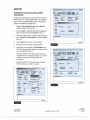
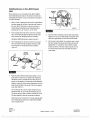
Enabling the Lift Axle Function (4S /3M
Installations)
To
InJnECU BeYV Comma Tests
MaMy
1_4(iN IA
I1yric.l 41
`
ECU Information
enable the lift axle function, you will need a PC with TOOLBOXTM
Software, version 4.6 or higher, installed. Refer to the TOOLBOXTM
User's manual for complete operating instructions. This manual
l
4U Type
IT aller TCS II
Configuration
14S
Part Nimber
(4465001030
/3M
04
Hai,
23/2D41
Serial Number
110027453
Software Revision
ledcb
I
jtl
Faaa- -0,MRAA'
{
--
Manulacture Date
is
posted on our website at meritorwabco.com.
1.
_sow
lat1eMbwurn rime. MSDleQ,elta
mrv
Display the Trailer ABS Main Screen. Click on Modify to
SIOrM
UI Sole Stalin
Not
Baia
'
display the pull down menu. Figure A -1.
I
2.
Lift Axle,
Click on
1
ÍIIIII
I
INemel
default status and activate the lift axle function,
To change the
Cbcf9,
s«ea
I
display the default lift axle status Not Active. Figure A -2.
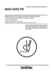
3.
q
PVm
The default lift axle screen will appear and
Message Center:
click on Change. The Litt Axle Status will change to Active.
Figure A -3.
...
4.
Click on Close to close the screen. Exit TOOLBOXTM.
5.
Remove power from the vehicle; then reapply power.
6.
Follow Steps 2 and
3
4005428a
Figure
Matt., wean inSet MS O.aqtwtin
Data CuaarreelTeRS tally ,W
1,
the lift axle function does not indicate active status, verify
to receive a not active status message, contact the
:I iala1 fi)411 Ì`'13,`'
+
ECU
TOOLBOXTM version 4.6 or higher is installed. If you continue
Morse/Ion
ECU Type
I
Trailer TCS
¡
Disconnect TOOLBOXTM from the vehicle and proceed with
Part Nu
()i Lift Axle
Faults
end of line testing as described in this bulletin.
Lift Axle Status
i_
Component Tests , Mealy
'OBI
p¡~I
(1#i
.V44
Part
Nurier
Feuke
Existing
Stored
TediMatio°n
r
t'r'
II
I
Software Revision
Voltages
-
Il
lAclive
I'y'rl
J
owe
Secondary
loll
Service Miles
io
Internal
113.5
Revs/Mile
1502.0
L.,r
.
Message Center.
R 2001
r
4465001030
Yes
"'"
War>tLOCatbn/OEM
4013M
23/2001
san.ae_
Primary
q
Notebook
'Trailer TCS
Configuation
Voltage
Help
Reconfigure
ECU Information
ECU Type
.mJ0J
Trailer ADS Diagnostics
Cagey
Manufactue Date
Edstiig
Stored
Tracer ECU
II
Confgu..
for assistance.
entreat WADLO
al215-1I
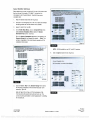
pboasECU
active, as illustrated in Figure A -3.
7.
A -2
to display the Lift Axle Status screen.
Verify the lift axle status display indicates the lift axle function is
If
.--
7453
ledcb
Wheel Sensor Speed (RPM
-
YEt
<7
BU1
<7
YE2
<7
BU2
<7
I
I{
_____40054293
Figure A -3
Service Information
Ilia
Primary
113.5
Current
Secondary
10.0
Service Mies
Internal
113.5
Revs/Mie
0.0
10
502.0
Message Center:
L
r
.
4005427a
Figure A -1
TP -20214
(16579/22882)
Printed in USA
Copyright ArvinMeritor, Inc., 2005
Revised 10-05
Page 21
PDF compression, OCR, web optimization using a watermarked evaluation copy of CVISION PDFCompressor
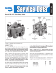
Installing Sensors on Non -ABS- Prepped
Axles
Sensor locations vary due to suspension type. Mentor WABCO
recommends placing the sensor on the axle that will provide the
most braking performance. Contact your suspension manufacturer
for further information.
1.
Apply a mineral oil -based grease that contains molydisulfide to
the sensor spring clip, the body of the sensor and the bore of
the sensor block. The grease must be anti -corrosive and
contain adhesive properties that will continuously endure
temperatures from
2.
-40° to 300 °F ( -40°
to 150 °C).
Figure
side, until the spring clip tabs are against the sensor holder.
5.
Push the sensor into the spring clip as far as possible.
Install the wheel hub carefully so that the tooth wheel pushes
against the sensor as the wheel bearings are adjusted. There
should be no gap between the sensor and the tooth wheel.
Use Mentor WABCO spring clips to ensure a correct fit.
3.
A -5
Push the spring clip into the sensor holder from the inboard
Push the spring clip into the sensor holder from the inboard
side until the spring clip tabs are against the sensor holder.
6.
Test the sensor output voltage. Use a volt/ohm meter to check
the output voltage of the sensors while rotating the wheel at
approximately 1/2 revolution per second. Minimum output
Push the sensor into the spring clip as far as possible.
must be 0.2 volt AC.
Figure A -4.
If
minimum output is less than 0.2 volt
AC, push the sensor toward the tooth wheel. Recheck the
sensor output.
Figure
4.
A
-4
Route the sensor cable toward the brake chamber, over the
brake spider or through the pre- stamped hole dedicated for
ABS sensors. Route to the back side of the axle. Secure the
cable to the axle between the brake spider and the suspension
brackets. Continue to route the sensor cable behind the spring
seats. Secure the cable to the axle one inch from the molded
sensor plug. Figure A -5.
Do not overtighten tie wraps on a cable. Overtightening can
damage the cable. Do not tie wrap the molded sensor plug.
The sensor extension cable must follow the brake hose to the
ECU /valve
assembly to allow for axle jounce and rebound.
Brake hose clips with a provision for the sensor extension cable
are recommended as opposed to tie wraps. Mentor WABCO
does not supply this part.
TP
-20214
Revised 10 -05
Page 22
(16579/22882)
Copyright ArvinMeritor, Inc., 2005
Printed in USA
PDF compression, OCR, web optimization using a watermarked evaluation copy of CVISION PDFCompressor
-
1~
1
DR!VETRAIN PLUS"
¢,THE
COMPLETE SYSTEM
ArvinMeritor,.
o
MERITOR WABCO
Mentor WABCO Vehicle Control Systems
2135 West Maple Road
Troy, MI 48084 -7121 USA
800-535-5560
meritorwabco.com
Information contained in this publication was in effect at the time the publication was approved for printing and is subject to
change without notice or liability. Mentor WABCO reserves the right to revise the information presented or to discontinue the
production of parts described at any time.
Copyright 2005
ArvinMeritor, Inc.
All Rights Reserved
TP -20214
Revised 10 -05
Printed in USA
(16579/22882)
PDF compression, OCR, web optimization using a watermarked evaluation copy of CVISION PDFCompressor