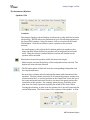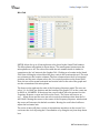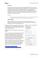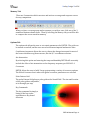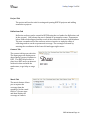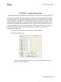
1
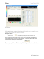
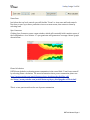
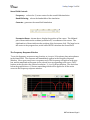
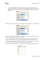
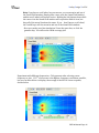
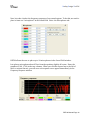
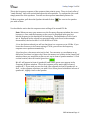
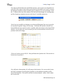
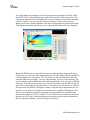
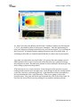
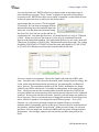
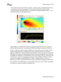
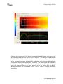
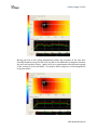
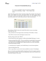
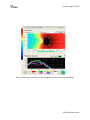
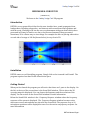
Danley Design Tool 2d USER MANUAL FOR DDT 2D ( VERSION 1.8) Welcome to the Danley Design Tool 2D program. Introduction DDT2D is a very powerful tool that lets the user visualize how sound propagates from loudspeakers, including subwoofers, and interacts with sound from other speakers and with the room. Working in 2D lets the user see phenomena with great detail which when presented in 3D may be hard to see due to the increased amount of data presented. Sometimes, 2D is a better way to view things. For example the effect of placing subwoofers on each side of a stage at 100 Hz (shown below) is very clear in 2D. Installation DDT2D comes as a self-‐installing program. Simply click on the icon and it will install. The program requires less than 20 mb of hard drive space. Getting Started When you Jirst launch the program you will notice that there are 3 parts to the display. On the left, at the top of the screen there is the Sound Field window. This is where the 2D coverage maps are displayed. You can choose the frequency and the resolution of the display. See the section on the Sound Field window for more information. Below the Sound Field window is the Frequency Response window where the frequency response of the system is displayed. The Frequency Response window becomes active when one or more microphones are placed in the sound Jield. The response of up to 10 microphone positions can be displayed at once. See the section on frequency response for more information. DDT 2d Manual Page 1 Danley Design Tool 2d DDT2D Screen On the right, there are a number of drop-‐down tabs allowing the user to design the system to model. We call this part the Parameters Window. Moving the Panels When you see this symbol you can grab it with the mouse and move the panel anywhere on the screen. this way you can customize the look of your screen and keep active tools that you use frequently. To return all panels to the default position click the default panel location button. The menu bar may be “torn off” in its entirety. When it is, you will have to double-‐click on a tab to open it. DDT 2d Manual Page 2 Danley Design Tool 2d The Top Level Buttons Moving the mouse over the buttons on the top left of the screen will display a “roll over” description of the function of the button. From left to right these are: Create a New Project -‐ start with a clean slate! Open an Existing Project -‐ opens the Windows Browse window Save a Project -‐ opens the Naming window and allows the user to save a project. Draw Line -‐ allows user to draw a line freehand in the Sound Field window Erase Line -‐ click erase line then mouse over the line you wish to remove Erase All Lines -‐ removes all lines from Sound Field Measuring Tool -‐ measures distances in Sound Field window. Distance in feet ( or meters) and time in ms are displayed directly above the sound Jield window. Activate Scroll Bars -‐ if the display is too small to show the entire DDT2D display, you can activate the Windows scroll bars. Maximize/Minimize Sound Field Window -‐ clicking this button will enlarge the Sound Field window to occupy most of the screen. Clicking again will return the Sound Field to default size. Note, while window is maximized it will cover up most of the pull down tabs. You will need to double click a tab to open it. Default Panel Location -‐ returns all panels to default locations. ( see Moving Panels) Memory -‐ records Sound Field and Frequency Response to one of 3 memories. View using Memory tab. Sound Pressure Level, A C and F Weighting -‐ selecting these buttons ( with an active microphone) will call up a small box attached to the microphone indicating the Sound pressure level at that point Current Units -‐ displays the current unit selection and toggles between feet and meters. DDT 2d Manual Page 3 Danley Design Tool 2d Zoom Save Just below the top level controls you will Jind the “Zoom” or view save and load controls. Use these to save up to three particular views or screen zooms, then return to them by selecting load. Spec Generator Clicking Spec Generator opens a new window, which will eventually hold complete specs of the loudspeakers. As of version 1.7 spec generator will generate a coverage contour graph shown below. Phase Calculation DDT2d now defaults to showing power summation in the sound Jield. Turn Power sum off by selecting Phase calculation. For more information about power summation please see http://www.youtube.com/watch?feature=player_detailpage&v=KoiGMu_ir88 And http://www.youtube.com/watch?feature=player_detailpage&v=sR7kctrfcnE This is a two part tutorial on the use of power summation DDT 2d Manual Page 4 Danley Design Tool 2d Sound Field Controls Frequency-‐ selects the ⅓ octave center for the sound Jield simulation Band Widening -‐ selects the bandwidth of the simulation Generate -‐ generates the sound Jield simulation Parameter Boxes -‐ shown above, display the position of the cursor. The lefthand pair of boxes indicate the realtime position in X,Y coordinates of the curser. The righthand set of boxes indicates the position of the last mouse click. The large box in the center is the progress box, active while DDT2D calculates the Sound Field The Frequency Response Window To see the frequency response at any location, or in up to 10 locations, place microphones in the Sound Field. The response will immediately appear in the Frequency Response Window. Move your curser over a response curve. The frequency will appear in the grey box, and the amplitude will appear in the colored box corresponding to the curve. The 3 buttons at the top select the vertical resolution , 3 , 6 or 10 dB per division. The check box below the graph selects a 1/3octave smoothing which will be applied to all the active curves in the frequency response window. DDT 2d Manual Page 5 Danley Design Tool 2d The Parameters Window Speakers Tab Location Selecting the Speakers tab will display 4 sub menus or tabs, with the Location tab showing. DDT2D allows the placement of up to 20 full-‐range speakers in the Sound Field window. Using the mouse, click on a location in the Sound Field window. Click the set button to place a speaker in the position selected . -‐ the small square to the right of the Set button, makes the speaker active when checked. When checked, the speaker will be displayed in the Sound Field. When de-‐selected ( unchecked) the location will remain but the speaker will be invisible. Mute button, leaves the speaker visible, but mutes the output. -‐ Phase button, reverses the polarity of the loudspeaker when selected. The button will turn red when selected -‐ The ID button when clicked, will turn the corresponding loudspeaker red for easy identiJication. -‐ the next three columns allow for manual placement and orientation of the speakers. The Jirst column selects the X or horizontal position, and the next column selects the Y or vertical position on the Sound Field. Note: the use of the terms horizontal and vertical refer to the axis of the graph and not the orientation of the speaker. For example, when viewing a speaker in the plan view, the Y axis represents typically the width of the room. When viewing the elevation, or side view of a speaker, the Y axis will represent the vertical dimension. The Jinal column is the rotation of the speaker. In Plan DDT 2d Manual Page 6 Danley Design Tool 2d view, using the angle control will rotate the speaker about its vertical axis, with a negative angle turning the speaker clockwise. When using a side or elevation view, the angle control tilts the speaker up or down with a negative angle pointing it downwards. -‐ Groups. An individual loudspeaker can be assigned to 1 or all of 4 groups. All loudspeakers assigned to a group can be controlled as a group, by using the controls in the Groups section at the bottom of the Speakers window. The group can be muted, the polarity of the entire group Jlipped, the gain can be changed, delay added and the angle of the speakers in the group adjusted. Using the 4 boxes next to the group select the group can me moved anywhere on the screen. The Master section, to the left of the Groups section adjusts the gain and delay of all loudspeakers. Processing Selecting the Processing tab brings up a new window where the gain and delay of a speaker can be adjusted. The set, on/off, mute and polarity functions remain active. Crossover The crossover tab can be used to set the high pass crossover for the loudspeaker. The check box turns the crossover on and off. There are two ways that a crossover can be set for a loudspeaker . The Global crossover is adjusted under the Options tab. Use the Global crossover if all the crossovers in the system are likely to be identical. The settings of the Global crossover are shown greyed out if the Global crossover is chosen. The crossover can also be set to Local. The Local crossover affects only the selected loudspeaker. Selecting the Local option activates the Frequency, Type and slope windows. The frequency can be set to any value from 20 to 9999 Hz. DDT 2D supports 3 types of Jilters, Bessel, Butterworth and Linkwitz-‐Riley, in 4 slopes 6, 12, 18 and 24 dB per octave. Model When the Model tab is selected a new window is displayed where the user can select from among the Danley Sound Labs family of full-‐range ( i.e. not subwoofers) loudspeakers. Each loudspeaker is listed in both plan view or side view. The set, on/off, mute and polarity functions remain active. DDT 2d Manual Page 7 Danley Design Tool 2d Subs Tab Location The Subs tab/ Location is identical in function to the Speakers Tab described above. The user may place up to 20 subwoofers in the Sound Field window. Processing The processing tab is identical in function to the Speakers tab/ Processing described above. Crossover The Crossover tab is identical in function to the Speaker tab/ Crossovers described above Model The Model tab is identical in function to the Speakers Tab/ Model described above. DDT2D version 1.48 includes 3 of the Danley subwoofers, the TH812, the DBH 218LC, and the TH118. In addition, we have included an idealized “ true omni” subwoofer. DDT 2d Manual Page 8 Danley Design Tool 2d Mics Tab DDT2D allows for up to 10 microphones to be placed in the Sound Field window. The Microphone tab window is shown above. The small square button turns the microphone on or off. The colored box with the mic number inside is similar in operation to the ‘set’ button in the Speaker Tab. Clicking on a location in the Sound Field then clicking the colored box will place a mic in the location selected. The next two columns are the location columns. The Jirst column selects the X or horizontal position, and the next column selects the Y or vertical position on the Sound Field. Note: the use of the terms horizontal and vertical refer to the axis of the graph and not the orientation of the microphone. The boxes on the right set the scale of the Frequency Response graph. The user can select 3, 6, 0r 10 db per division, and the bottom of the graph i.e. 0 on the y axis can be 80,90 or 100 dBSPL. If the mouse has a scroll wheel, place the mouse over the Frequency Response screen and click on the Y axis. The curser will turn to an up/ down arrow and the user can select vertical resolutions other then the 3,6 and 10 dB. Moving the curser to the center of the Frequency Response window and the curser will return to the default crosshair. Moving the scroll wheel will now adjust the horizontal axis. The circle of mics will place a circle of microphones anywhere on the screen. You can locate the circle by using the X Coordinates or by using the set from drop-‐down box. DDT 2d Manual Page 9 Danley Design Tool 2d Draw Tab The Draw tab gives access to a number of drawing tools which let the user create complex rooms in the Sound Field window. IMPORTANT! The lines drawn with the tools under the Draw tab, have no acoustic properties. The sound goes right through them. DDT2D allows for freehand drawing or drawing using the X/Y coordinate method. See Tutorial #1 for a detailed demonstration on how to draw with the X/Y coordinate system. Arbitrary shapes, circles and text boxes can be placed on the Sound Field window. CALC Tab External Image DDT 2d starting at version 1.8 allows you to import an image and set it a a background in the sound Jield window. This is particularly useful for importing images of sports facilities from google earth. The CALC Tab was discontinued in version 1.7. The calculator functions are available as apps for iPhone/ iPad from the Apple Store Clicking on the box “import external image” calls up the Windows Jile browser window. Images to import must be .png Jiles. Click Show image to turn on the image in the sound Jield. Opacity sets the level of transparency for the import images. To use the scale feature you must know the true size of some object in the image. For example, if the image is of a football Jield, you can use the width of 160 feet as a reference. Use the measure tool in menu bar above the sound Jield and click and drag across the element to be measured. The measured dimension will appear in the “last measured distance” window. Then enter the desired dimension in the “real Distance should be” window. Click on calculate scale and apply to image. The image will rescale. For a demo on importing and scaling an image see the video readme Jile for DDT 1.80. http://www.youtube.com/watch? feature=player_detailpage&v=RD4Q1gZEC7I DDT 2d Manual Page 10 Danley Design Tool 2d Memory Tab There are 3 memories which can store and retrieve coverage and response curves for easy comparison. When you have a coverage map and a response you wish to save, click one of the 3 numbered buttons shown above. Then by selecting the Memory tab you will be able to compare the curves saved in memory. Options Tab The options tab allows the user to set certain parameters for DDT2D. The grids can be turned on and off, and the user can select between imperial and metric units. Coordinates increment allows the user to choose the change increment for most of the boxes which have up/down arrows, like the X, Y coordinates selectors. Air Attenuation By selecting this option and entering the temp and humidity DDT2D will accurately include the effect of air attenuation on the frequency response, per ISO 9613-‐1. Crossovers DDT2D allows the user to build 2 way systems using a variety of crossover options. The Global Crossover box is where the global crossover parameters are selected. Polar Pattern Grid The polar Pattern Grid places a polar grid on the Sound Field. The size and location of the polar grid are adjustable, as is the angle per step. Key Commands The key command is simply a listing of the key stroke equivalents or key board shortcuts. DDT 2d Manual Page 11 Danley Design Tool 2d Project Tab The project tab has the tools for saving and opening DDT2D projects and adding notations to projects. ReYlections Tab ReJlective surfaces can be created in DDT2D using the tool under the ReElections tab. In the current ( 1.48) release the user is limited to rectangular rooms. Frequencies below 3kHz can be mapped and the result of the reJlections shown in both windows. The user can make each of the surfaces active or inactive to study the effect of reJlecting surfaces on the response and coverage. The rectangle is formed by entering the coordinates of the lower left and upper right corner. Connect Tab The connect tab has two sub tabs. The News page will display news about Danley events or updates to DDT. The DDT Help forum is a place here DDT users can interact with each other and with the moderators, to get help or usage tips. Movie Tab The movie feature allows you to capture the coverage from the speaker(s) in the sound Jield in ⅓ octave steps and then display the coverage as a movie. DDT 2d Manual Page 12 Danley Design Tool 2d TUTORIAL 1. A simple sound system Please note: some of the illustrations in this tutorial are from an earlier version of DDT 2D As a way to get familiar with the various parts of DDT2D, lets design and model a simple 2 way sound system. Lets start with a PLAN view of the system. The PLAN view is looking down from above. With DDT2D you don’t need to build a room unless you want to. You can examine the way speakers couple, for instance, without building a room Jirst. So lets look at a few options before we put them in a room. Suppose we are trying to decide if a pair of loudspeakers would be best placed together in the center of the room, or one on each side of the stage. Lets assume the the stage is 18 feet wide. Lets Jirst place a loudspeaker on stage right. -‐Click on the Speakers tab on the right hand Variables Window -‐ Now select the Model tab. you can see that DDT2D allows you to place 20 loudspeakers and create groups -‐ more on that later. DDT 2d Manual Page 13 Danley Design Tool 2d -‐ Lets choose the SH100 from the pull down arrow on the right end of the box showing the SH60 Side view. Because we are modeling in 2d, the user has to decide between the side view or the Plan view. For this example we are using the SH100 plan view Selecting the box indicated by the arrow, makes the chosen speaker active. The M button next to it, is a Mute button, which leaves the speaker on the screen, but mutes the output. The phase button Jlips the polarity of the speaker. -‐ Now select the Location tab. This will let us place the loudspeaker on the Sound Field screen. The Jirst column in the X or horizontal position. The next column is the Y or vertical position. Remember that this is a 2D model. The words Horizontal and Vertical are relative! Lets set the position of the Jirst speaker at 20.00 , 10.00 -‐ Choose a second SH100 and place it at 20.00, 28.00. You should see something like this. DDT 2d Manual Page 14 Danley Design Tool 2d Note, if you have a scroll wheel on your mouse, you can zoom in and out of the Sound Field window. Simply place cursor over the Sound Field window and the scroll wheel will become active. Holding the Left button down while the cursor is in the Sound Field window will re-‐position Jield of view, but keep all of the actual locations the same. If you don’t have a scroll wheel, the I and O keys will also zoom in and out of the Sound Field window. -‐ Now you can do your Jirst simulation! Press the space bar, or click the generate key. You will see the 1KHz coverage plot. Experiment with different frequencies. Click generate after selecting a new frequency to plot. 1/12th of an octave is the highest frequency resolution, possible, but you can also choose to display the average of the full 10 octave response, shown below. DDT 2d Manual Page 15 Danley Design Tool 2d Now, lets take a look at the frequency response of our sound system. To do this, we need to place at least one “microphone” in the Sound Field. Select the Microphones tab. DDT2d allows the user to place up to 10 microphones in the Sound Field window. Lets place a microphone about 45 feet from the speakers slightly off center. Enter the numbers 65.00 , 17.00 in the two columns. When you click the square box to the left of Mic1 to activate the mic, you will see a red response curve appear immediately in the Frequency Response window. DDT 2d Manual Page 16 Danley Design Tool 2d This is the frequency response of the system at that point in space. There is clearly allot of “comb Jiltering” due to the arrival times from the two speakers. To conJirm this you could simply mute one of the speakers. You will see the response immediately Jlatten out. To Mute a speaker, pull down the Speaker tab and click on you wish to Mute. the next to the speaker You should also notice that the response starts rolling off at around 150 Hz. Note: When you move your mouse over the Frequency Response window the cursor becomes a cross, and the frequency at the cursor is displayed in the grey box labeled frequency at the bottom left of the display. The amplitude or level of each mic is displayed in the colored box associated with each curve. In the example shown above, the level at Mic 1 is 105 dB SPL at 970 Hz. -‐Go to the Options tab and you will see that there is a crossover set at 150 Hz. If you lower the crossover to its lowest setting of 70 Hz, you will see the frequency response curve update automatically. -‐Now lets place a few more mics just for fun! You can enter x,y coordinates as we did before, but there is a faster way! Move the mouse to a location in the Sound Field window where you would like to place a mic, say in front of speaker number 2. Click on that location, then click on the green box Mic # 2 will appear in front of speaker#2, and a new, green curve appear in the Frequency Response window. This is the response pretty much right in front of speaker # 2. If you wish you can also look a the response in front of speaker #1 as well, or the response anywhere you wish! Here I have placed a third mic in front of speaker #1, slightly closer to the speaker. DDT 2d Manual Page 17 Danley Design Tool 2d -‐You may recall that when we started this exercise , we set out to see if speakers on each side of the stage is better then a pair placed in the middle over head. Lets save this design in memory so that is will be easy to compare it to our next design. Click the 1 button at the top of the window. This will save this design, the coverage map and the frequency response screen to the Jirst of 3 available memories. -‐Now, lets try to modify our design to see what would happen if we were to put the two speakers together hung over the stage. Pull down the Speakers tab and lets learn a different way to move or place a speaker. Move the mouse to the Sound Field window. As you move the curser around, you will see the numbers in the left set of position boxes will change. -‐Click at a location close to 20,18. Now pull down the Speakers tab. Click on the set button next to speaker 1. -‐You will notice that speaker # 1 will jump to this location. You can use this “point and click” technique to quickly place speakers or microphones anywhere in the Sound Field window. You can also edit the location using the x and y Jields under the location tab. DDT 2d Manual Page 18 Danley Design Tool 2d -‐Ok, using what ever technique you wish, lets get the two speakers to 20.00, 18.00 and 20.00, 19.00. This will place the speakers side by side. Click on generate. The response is much better in the middle, but now there huge notches in the response on mic # 2 and 3. You can save this design to memory 2. If you select the tab Memory from the Variables Window, you will see the graphics from the Jirst design. Clicking on the number tabs allows you to compare the results of the two designs. Maybe the SH100 was not a good choice because although they couple well at low frequencies, ( see the very close agreement from all 3 mics below 600 Hz) the SH100 is not designed to be “arrayable”. You can clearly see the cancellations in both the response and in the coverage. Lets try a third design. If you go to the Speakers tab, you can simply click on Model and select different speakers. Lets try a pair of SH50s, plan view. You will need to zoom in to see it, but if you place the two SH50 at the 18 and 19 ft locations they will hit each other. So lets put one at 18, and one at 19.80 ft. Then, because the SH50 is a 50 degree cabinet, using the Angle adjustment tool, set speaker 1 to an angle of -‐25 degrees, and speaker 2 to an angle of 25 degrees. Now the two can be moved together so that they are tight packed. You should end up with the two speakers at 20. 18.9 and 20 , 19.8 or some set of coordinates where the speakers are .9ft apart. Notice the improved coverage and the smooth response as the two speakers combine. Save this design to memory 3. DDT 2d Manual Page 19 Danley Design Tool 2d -‐So, now if you select the Memory tab from the “variables” window, by choosing tab 1 , 2 or 3, you should be able to review your 3 designs! Take this opportunity to save your design by clicking on the disk icon ( save current project) or by clicking on the Project tab. You might consider naming this project my_Jirst_model_plan or something to that effect to remind yourself that this is a plan view of your system. -‐Lets take our exploration one step further. It is pretty clear that putting a pair of SH50 speakers in the center of our room will be the best way to get the coverage and response we want. But what if we wanted to add a subwoofer. Should we Ely it up in the ceiling or place it on the ground? -‐The Jirst step is to re-‐ orient ourselves. In the last part of this exercise, we were looking down from the top at the plan view. Even though we did not actually build a room, the y axis was representing the left -‐ right dimension of the room and the x axis represented the front -‐ back dimension. Now we are going to look at the elevation view. The y axis will be the up-‐down and the x will be the front-‐ back. So lets clear the Sound Field screen by turning off our speakers and microphones. DDT 2d Manual Page 20 Danley Design Tool 2d -‐Lets try the Draw tool. DDT2d allows you to draw rooms of any shape to get a better handle on coverage. These “rooms” or shapes do not have any acoustical properties at all. DDT2d does allow you to build rectangular rooms which do have acoustical properties, but we will cover that feature later. Lets assume that our room is 75 feet long and 25 feet high. We can draw a rectangle of those dimensions using the tools available under the Draw tab. You can draw lines freehand using the Draw Line tool, but lets use the add line by coordinates tool. Lets draw the Jloor Jirst. x1 should be 0.00, y1 0.00, x2 75.00 and y2 0.00 . When you click on “line from (x1,y2) to (x2,y2) a horizontal line will appear in the Sound Field window. This represents the Jloor of our room. Next add a line from (0.00,0.00) to (0.00,25.00). This should draw the front wall. The ceiling should be (0.00,25.00) to (75.00,25.00) and the back wall should be (75.00, 25.00) to (75.00, 0.00). When you are done the room should look like this. -‐Now we can place our speakers. Choose the Speaker tab, and select SH50, side view. Lets place one, 10 feet from the front wall, and 2 ft down from the ceiling. We could point at the desired position and click set, but entering the coordinates is more precise. The coordinates should be (5.00, 23.00). Remember our design called for two SH50s side by side. Lets add a second speaker at the same location. Even though we cant see the second speaker from this perspective, DDT2d will accurately model the sound pressure level and frequency response of the combined speakers. Notice in the Location tab under Speakers, you can assign any speaker to one of 4 groups. This is a convenient way to change the position or processing of an entire cluster of speakers. Lest assign our two SH50s to group 1. If we click Generate, we can see that we need to angle our speakers down to cover the audience which, presumably, will be on the Jloor! Now use the tool at the bottom of the Speakers window labeled “Group Section” . Make sure that Group 1 is selected, and enter -‐20 in the angle box. Both of the SH50s will now point 20 degrees down. Re-‐generate the coverage , and you will see that the speakers now point at the Jloor! DDT 2d Manual Page 21 Danley Design Tool 2d -‐Lets add a few mics to check the response. Place one mic towards the back of the room and one about half way down. You should see that the response looks virtually the same in both positions, the nearer one being somewhat louder. Your model should look something like this. -‐Now, Jinally, we can add our subwoofer and experiment with location. Lets start with the Sub on the Jloor. Lets choose the TH118, and place it under the SH50s on the Jloor. Because of the size of the TH118, the Y axis will need to be about 1.4 ft to show it sitting on the Jloor. Make sure that the crossover buttons are selected (default condition) on both the SH50s and the TH118. The crossover select button is under the Processing tab. Reviewing our Danley Sound Labs Spec sheet, we see that the SH50is rated down to 50 Hz and the TH118 is rated up to 225 Hz. This means we could select a crossover frequency somewhere between 80Hz and 225 Hz. This is one of the strengths of using DDT2D to evaluate a sound system. You can try different crossover frequencies, different slopes and different alignments to Jind the best possible set of parameters. Lets start with a crossover set to 100Hz. Remember, the crossover point is set under the Options tab. DDT 2d Manual Page 22 Danley Design Tool 2d Choosing the frequency of 100 Hz and setting the Band Widening to 2 octaves will let you see how the SH 50s and the TH118 interact. You can see from the Sound Field that there is considerable interference between the two. It can also be seen in the frequency response. Adjusting the gain, delay and crossover characteristics can improve this system signiJicantly. However, it is unlikely that you will Jind a combination of settings where the response at the 2 microphones will be the same. Lets look what happens if you move the sub up to the ceiling with the SH50s. Moving the Sub to the coordinates of 6.00 / 20.30 with a -‐20 angle (not really necessary) DDT 2d Manual Page 23 Danley Design Tool 2d Moving the Sub to the ceiling immediately makes the response at the two mics virtually identical except for the level loss due to the difference in distance between the mics and speaker cluster. Again, feel free to experiment with different settings of the crossover, levels and delay. You may be able to improve on this design!Here is my best effort! DDT 2d Manual Page 24 Danley Design Tool 2d Lets do one more thing. Because our room is ( conveniently) rectangular, we can actually look at what effect the room will have on our design. This is a worst case condition, where each of the surfaces is assumed to be 100% reJlective. Select the ReElections tab. If you enter the coordinates of the lower left corner, 0, 0 and the top right corner 75, 25 you will create a rectangle of reJlective surfaces which overlays the room we built earlier. Of course you will notice immediately that our carefully tuned and “tweaked” sound system looks horrible. This is what it would look like in a reverb chamber with everything totally reJlective. In the real world it will not be this bad. You will also notice that the Sound Field takes considerably longer to calculate. DDT 2d Manual Page 25 Danley Design Tool 2d Tutorial #2 A Cardioid Bass Array As a way to get familiar with the operation of DDT2D, lets start by modeling a simple 3 box Cardioid bass array. -‐Select the Subs pop down menu. You will see three tabs, Location, Processing and Model. Select Model. Lets use the sub labeled TH118. We will be using 3 subs in our model, so make sure that subs 1,2 and 3 are all set to the TH118 sub. Now select the Location tab. Set the Jields in the Jirst 3 subs as shown below. This will place 3 TH118 subs in the Sound Field with the center one pointing backwards from 1&3. -‐ Now pull down the Processing tab and set the delay of TH118 #2 to 2.20 ms. -‐ Turn off the crossover by de-‐selecting the crossover box -‐Flip the polarity of the center TH118 -‐ In the Sound Field set the frequency to 80 Hz with the Band Widening to 1 octave. -‐ Generate a Sound Field NOTE!! The screen will likely be totally black if you generate a Sound Field with out Elipping the polarity of the center sub. You have essentially gone off the top of the amplitude scale. Reduce the drive level to all 3 subs and the Sound Field will map normally. -‐ A convenient way to optimize your Cardioid array is to use the microphones. -‐ Select the Microphones Tab -‐ Here is a good time to try the circle of mics available in version 1.48 and higher. Place a circle of mics around the middle sub and you will see the response appear in the freq response window. Select the smoothing feature and you will clearly see the directional response of this array DDT 2d Manual Page 26 Danley Design Tool 2d Your cardioid array should look something like this. Have fun experimenting! DDT 2d Manual Page 27