1
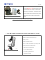
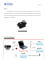
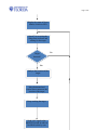
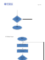
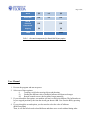
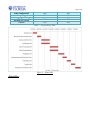
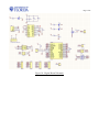
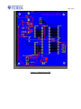
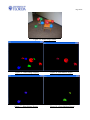
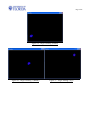
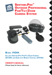
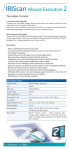
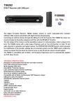
Page 1/22 EEL 4914C Electrical Engineering Design (Senior Design) Final Report Project Title: Beach Ball Sniper August 4, 2009 Team Name: Team Members: Jeff Johnson JinWoo Roh (Mir) [email protected] 813-388-0335 [email protected] 904-505-4756 Project Abstract This project deals with tracking balloons in real time and shooting it with a projectile. This project will track the ball in a vertical and horizontal plane but will not consider the issue of depth; therefore, the firing mechanism will be able to rotate on two axes. It also recognizes multiple colors of balloons and shoots each color individually. This is accomplished using image processing and a pivoting device and the firing mechanism. This project could be extended in the future to track more complex objects and could have applications in the military contracts or various other fields. Page 2/22 TABLE OF CONTENTS Project Abstract ................................................................................................................................ 1 Table of Contents .............................................................................................................................. 2 Table of Figure .................................................................................................................................. 3 Introduction ...................................................................................................................................... 4 Project Features & Objectives........................................................................................................... 4 Analysis of Competitive Products .................................................................................................... 5-6 Concept and Technology ................................................................................................................... 7-9 Project Architecture........................................................................................................................... 10 Software Flowchart ........................................................................................................................... 11-13 Bill of Materials ................................................................................................................................ 14 User Manual ...................................................................................................................................... 15 Division of Labor/Gantt Chart .......................................................................................................... 16 Appendices ........................................................................................................................................ 17-21 Reference .......................................................................................................................................... 22 Page 3/22 LIST OF TABLES OF FIGURES Figure 1: NinJa Pan’n Tilt Surveillance Camera Mount ........................................................................... 5 Figure 2 : SUPA-TRAK MULTI PURPOSE AUTO-TRACKING MOUNT.......................................... 6 Figure 3: webcam from logitech ............................................................................................................... 7 Figure 4: Dell XPS M140 laptop .............................................................................................................. 8 Figure 5: Atmel Atmega32 DIP ................................................................................................................ 8 Figure 6: OpenCV software logo .............................................................................................................. 8 Figure 7: Servo from GWS ....................................................................................................................... 9 Figure 8: Block diagram of project ......................................................................................................... 10 Figure 9 - Gantt chart ............................................................................................................................. 16 Figure 10 : Digital Board Schematic....................................................................................................... 17 Figure 11 : Digital Design PCB .............................................................................................................. 18 Figure 12 : Analog Board Schematic ...................................................................................................... 19 Figure 13 : Analog Board PCB ............................................................................................................... 19 Figure 14 : Actual Target Photo .............................................................................................................. 20 Figure 15: Whole Image Capture Figure 16: Red Balloon Targets................................ 20 Figure 17 : Blue Balloon Targets Figure 18 : Green Balloon Targets .......................... 20 Figure 19 : Target Tracking 1(Down) ..................................................................................................... 21 Figure 20 : Target Tracking 2 (Middle) Figure 21 : Target Tacking 3 (Up) ...................... 21 Introduction: This project is inspired by the need to unman the front lines in the armed forces of our country. Although this project doesn't deal with exact specifications that would be found in a defense contract, the core of this project can easily be abstracted to such applications. Our project has 3 options to choose from. 1. Tracking a solid color moving object and shooting. 2. Finding the different colored stationary balloons and shooting each target. 3. Remote control to move the location of target manually. Project Features & Objectives: We will use OpenCV to do image processing to track a solid colored balloon; this processing will take place on a laptop. The camera is fixed in place so the firing mechanism will have a Page 4/22 frame of reference. A fairly expensive high resolution camera was used because it provides faster frame rate and better quality data than the cheaper lower resolution camera. The laptop will send commands serially to micro processor (ATMEGA32) that will control the servo positions of the firing mechanism and whether or not to fire the airsoft gun. We used an FTDI chip to convert from USB to Serial (RS2332). A current sensing resistor is used to monitor the current that flow through the motors, and the value will be compared with the absolute maximum value. If high current flows, MOSFET switch will turn off the power to the motors. A mechanical platform that can quickly rotate on two axes will consist of two servos and a system of ball casters. Analysis of Competitive Products There are no competitors such application on the market. This sort of device does not exist commercially. However, This product could be extended for use by the military for such applications as shooting down incoming missiles or facial recognition software to identify persons of interests. We can use a part of our system as the Tracking Camera Mount. If we put a surveillance camera with servo motors, the camera will track the people who come to the stores. It will be very effective since using multiple cameras might not cover the whole area. NINJA Pan 'n Tilt surveillance camera mount ($99.99) Page 5/22 The robotic NINJA Pan 'n Tilt Camera Mount (camera not included) allows you to sweep your XCam2 video camera left, right, up and down – featuring 240° views and up to 4 preset positions! Remotely position camera to view whatever you want with included ScanPad Remote. Figure 1: NinJa Pan’n Tilt Surveillance Camera Mount SUPA-TRAK MULTI PURPOSE AUTO-TRACKING MOUNT ( $379.00) Latest mount with tripod from Sky-Watcher. Suitable for cameras and small telescopes. Battery powered. Handbox controller included. This is a versatile mount which is quite unique in that nothing like it has been offered before. * Single Arm Alt-Azimuth Mount * DC Servo Motor Assembly * IR Encoder with Optical Wheel * Astronomical Tracking Page 6/22 * Terrestial Stored Positions to GOTO * Cruise and Image for Terrestial Positions * Lightweight and Portable * Simple and Easy to Use * Auto Imaging and Aux. Power outlets to Camera/Spotting Scope Figure 2 : SUPA-TRAK MULTI PURPOSE AUTO-TRACKING MOUNT Concept and Technology Our project is made of two main boards, a digital board and an analog board. The digital board includes a FTDI chip, ATMEGA32, MOSFET Swtich, isolator, and a fuse. First, a USB webcam will collect the image data. Then, openCV will analyze the data and send commands to the atmega32 via USB conversion to TTL serial by the FTDI chip. Once ATMEGA32 receives serial commends, the micro controller will control two servo motors, a firing MOSFET trigger, and MOSFET. The analog board is made of mainly three opamps, a comparator, push switch, MOSFET switch, and a voltage regulator. It will keep monitoring the current going through the motors and compare the Page 7/22 value with the absolute maximum value. If the maximum current is exceeded, a MOSFEST switch will disconnect the ground of the motor to disable it. The peak current is usually caused by something against the servos. We implement this system to protect our servos and devices safely. In order to turn on the servos again a push switch has to be pressed manually because it prevents that the motors keep turning on and off as current changes irregularly. Webcam A USB webcam will be used to do the image capturing ideally this webcam will have low resolution and high data transfer rate. Low resolution will insure shorter execution time for the image processing code, the higher data transfer rate having obvious improvement. This is being investigated. Figure 3: webcam from logitech Laptop Both of our laptops should be able to execute the code maybe even a third computer which had no development done on it to insure portability. Development of the OpenCV code will take place mostly on Jeff Johnson's lap top, this is an existing item. Page 8/22 Figure 4: Dell XPS M140 laptop Micro Processor For ease of development we will use an Atmel atmega32 which has a free C/C++ compiler, AVR studio, which is a language we are familiar with. The atmega32 has more utility than we need and more than enough memory for data and programming space and costs only $6.00. Figure 5: Atmel Atmega32 DIP Image processing software Figure 6: OpenCV software logo We chose to use OpenCV due to its ease of use and again being a collection of C++ libraries which is a language we are familiar with. The libraries include many easy to use, well tested and efficient functions for typical image processing needs. Page 9/22 Servos Two 180 degree servos are used to actuate t he two axis rotating device, we chose to use a GWServo S03N STD servos because it has enough torque for out application and I already had them. Servos are widely used in electronics projects because they are easy to interface to and only require one PWM signal, VCC and GND Figure 7: Servo from GWS Project Architecture Sending Images GUI Display Program Web Cam OpenCV Image Capture Image Processing FTDI USB Cable Page 10/22 Visual Studio Serial ATMEGA32 Analog Board Firing Signals Left & Right Up & Down Current Sensing PWM Two Servo Motors Power On or Off Real Time Tracking MOSFET Switch MOSFET Trigger Behavior Firing mechanism / machine assembly Power Supply Figure 8: Block diagram of project I) Tracking a target Start No System operating normally? Debugging Yes Page 11/22 Display the status of Servo Motors Switch on LED OpenCV is receiving the image from webcam and waiting for the target Target detected? Yes Analyze the location of the target Move horizontal and vertical Servo motors to the location of the target Keep tracking the target Send “On” signal to the MOSFET Switch in order to fire BB if told to by user No Page 12/22 User specified end? End II) Multiple Targets Start openCV gets Image Break image into Red, Green, Blue Select Red or Green or Bleu Page 13/22 Shoot Red Shoot Green Shoot Blue User specified end? Yes End Bill of Materials Items Price Quantity Subtotal Servo Motors $10 x 2 $20 Web Cam $100 x 1 $100 ATMEGA Chip $7 x 1 $7 FTDI Chip $6 x 1 $6 Balloons $1.25 x 4 $5 Page 14/22 Wood $5 x 1 $5 Airsoft Gun $15 x 1 $15 Misc & Electrical Components $15 $15 Shipping $6 $6 Total $179 Table 1 ‐ Cost and components for Beach Ball Sniper project User Manual 1. Execute the program and turn on power. 2. Select one of three options: i) Tracking a solid color moving object and shooting ii) Finding the different color of multiple balloons and shoot each target iii) Remote control to move the location of target manually. 3. If you selected the first option, our machine will track a solid color balloon. The balloon has to be at a stopped position by the time the airsoft gun shoots a BB. User fires the BB by pressing ‘z.’ 4. If you selected the second option, you also need to select the color of balloons (Red/Green/Blue) Then, it will find all selected colored balloons and shoot once at each without hitting other Page 15/22 colors. 5. If you selected the third option, you can set up the location of the airsoft gun. It will move to indicated position and shoot if so indicated. Division of labor/Gantt Chart Responsibility Table Team Responsibility Table Research & Presentation CAD Design Board Design Analog Design OpenCV Programming ATMEGA Programming Jeff Johnson 50% 25% 75% 25% 75% 50% JinWoo Roh 50% 75% 25% 75% 25% 50% Page 16/22 Order Components Integrating Debugging / Testing Mechanical Design Overall 50% 50% 50% 50% 50% Table 2 – Responsibility Table Figure 9 - Gantt chart Appendices 50% 50% 50% 50% 50% Page 17/22 Figure 10 : Digital Board Schematic Page 18/22 Figure 11 : Digital Design PCB Page 19/22 Figure 12 : Analog Board Schematic Figure 13 : Analog Board PCB Page 20/22 Figure 14 : Actual Target Photo Figure 15: Whole Image Capture Figure 17 : Blue Balloon Targets Figure 16: Red Balloon Targets Figure 18 : Green Balloon Targets Page 21/22 Figure 19 : Target Tracking 1(Down) Figure 20 : Target Tracking 2 (Middle) Figure 21 : Target Tacking 3 (Up) Page 22/22 References Intelligent Machines Design Lab <http://mil.ufl.edu/5666/> NINJA Pan 'n Tilt surveillance camera mount : <http://www.x10.com/products/x10_vk74a.htm> SUPA-TRAK MULTI PURPOSE AUTO-TRACKING MOUNT (Figure ) : <http://www.trademe.co.nz/Electronics-photography/Binoculars-telescopes/Telescopes/auction231490591.htm> Image figure 2 (page4) : "webcam". logitech. 05/27/2009 <http://cache.gizmodo.com/assets/resources/2007/03/quickcam_2.jpg>. Image figure 3 (page5) : "XPS M140". Dell. 05/27/2009 <://absoluteraleigh.com/blog/uploaded_images/dell-xps-m140-775814.jpg>. Image figure 4 (page5) : "ATMEGA32 DIP". ATMEL. 05/27/2009 <http://rocky.digikey.com/weblib/Atmel/Web%20Photos/313-40-DIP.jpg>. Image figure 5 (page6) : piponazo , " Opencv 1.1pre + ffmpeg en Linux ". 05/27/2009 <plagatux.es/.../uploads/2009/04/opencv_logo.png>. Image figure 6 (page6) : "GWServo S03N STD Motors". GWD. 05/27/2009 <http://www.robotshop.ca/gws-standard-s03n-std-servo-motor-1.html>.