1
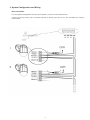
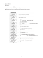
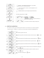
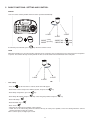
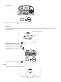
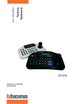
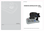
• Keypad with joystick and LCD display
430 502
430 603
LE03722AA
USER MANUAL
TABLE OF CONTENTS
INTRODUCTION
1. FEATURES............................................................................................................4
2. HARDWARE OVERVIEW.....................................................................................4
3. SYSTEM CONFIGURATION AND WIRING..........................................................7
SYSTEM INSTALLATION & TYPICAL APPLICATIONS
1. SYSTEM INSTALLATION.....................................................................................8
2. PTZ SETUP...........................................................................................................8
3. MAIN SETUP.........................................................................................................9
4. JOYSTICK CALIBRATION....................................................................................10
5. BASIC FUNCTIONS : SETTING AND CONTROL................................................11
6. SPECIFICATIONS.................................................................................................13
Warning
- The installation and calibration must be carried out by highly skilled personnel.
- Do not open there may be a risk of electric shock.
Use only for the following temperature conditions: from (-10) to (+50) °C.
Do not use with voltages different from the ones specified.
Safety instructions
This product should be installed in line with installation rules, preferably by a qualified electrician. Incorrect installation and use can lead to risk of electric shock or fire.
Before carrying out the installation, read the instructions and take account of the product’s specific mounting location.
Do not open up, dismantle, alter or modify the device except where specifically required to do so by the instructions. All Legrand products must be opened and repaired exclusively by personnel trained
and approved by Legrand. Any unauthorised opening or repair completely cancels all liabilities and the rights to replacement and guarantees.
Use only Legrand brand accessories.
2
IMPORTANT SAFEGUARDS
1. READ AND RETAIN INSTRUCTIONS
Read the instruction manual before operating the
equipment.
Retain the manual for future reference.
9. CORD AND CABLE PROTECTION
Route power cords and cables in a manner to protect
them from damage by being walked on or pinched by
items places upon or against them.
2. CLEANING
Turn the unit off and unplug from the power outlet
before cleaning. Use a damp cloth for cleaning.
Do not use harsh cleansers or aerosol cleaners.
10. LIGHTNING
For protection of the equipment during a lightning storm
or when it is left unattended and unused for long
periods of time, unplug the unit from the wall outlet.
Disconnect any antennas or cable systems that may be
connected to the equipment. This willprevent damage
to the equipment due to lightning or power line surges.
3. ATTACHMENTS
Do not use attachments unless recommended by
manufactured as they may affect the functionality of the
unit and result in the risk of fire, electric shock or injury.
11. OVERLOADING
Do not overload wall outlets and extension cords as
this can result in a risk of fire or electric shock.
4. MOISTURE
Do not use equipment near water or other liquids.
5. ACCESSORIES
Equipment should be installed in a safe, stable location.
Any wall or shelf mounting accessory equipment should
be installed using the manufactures instructions.
Care should be used when moving heavy equipment.
Quick stops, excessive force, and uneven surfaces may
cause the equipment to fall causing serious injury to
persons and objects.
6. VENTILATION
Openings in the equipment, if any, are provided for
ventilation to ensure reliable operation of the unit and
to protect if from overheating. These openings must
not be blocked or covered
7. POWER SOURCES
The equipment should be operated only from the type
of power source indicated on the marking label.
If you are not sure of the type of power supplied at the
installation location, contact your dealer.
For equipment designed to operate from battery power,
refer to the operating instructions.
8. GROUNDING OR POLARIZATION
Equipment that is powered through a polarized plug
(a plug with one blade wider than the other) will fit
into the power outlet only one way. This is a safety
feature. If you are unable to insert the plug fully into
the outlet, try reversing the plug. Do not defeat the
safety purpose of the polarized plug.
12. SERVICING
Do not attempt to service the video monitor or
equipment yourself as opening or removing covers may
expose you to dangerous voltage or other hazards.
Refer all servicing to qualified service personnel.
13. DAMAGE REQUIRING SERVICE
Unplug the equipment from the wall outlet and refer
servicing to qualified service personnel under the
following conditions:
A. When the power supply cord or the plug has been
damaged.
B. If liquid has spilled or objects have fallen into
the unit.
C. If the equipment has been exposed to water or
other liquids.
D. If the equipment does not operate normally by
following the operating instructions, adjust only those
controls that are covered by the operating
instructions. Improper adjustment of other controls
may result in damage to the unit.
E. If the equipment has been dropped or the casing
damaged.
F. When the equipment exhibits a distinct change
in performance.
14. REPLACEMENT PARTS
When replacement parts are required, be sure the
service technician uses replacement parts specified by
the manufacturer or that have the same characteristics
as the original part. Unauthorized substitutions may
result in fire, electric shock, or other hazards.
Alternate Warning: If the equipment is powered
through a three way grounding type plug, a plug having
a third (grounding) pin, will only fit into a grounding-type
power outlet. This is a safety feature.
Do not defeat the safety purpose of the grounding type
plug. If your outlet does not have the grounding plug
receptacle, contact your local electrician.
15. SAFETY CHECK
Upon completion of any service or repairs to the
equipment, ask the service technician to perform safety
checks to verify that the equipment is in proper
operating condition.
16. FIELD INSTALLATION
The installation of equipment should be made by a
Qualified service person and should conform to all local
codes.
3
INTRODUCTION
This remote keyboard is an accessory for PTZ dome camera, etc
It allows the user to control from 1 to 255 cameras.
1. Features
•
•
•
•
•
•
•
•
•
•
Controls from 1 to 255 cameras.
Multiple protocol supported in each channel (CMT, WDS,WCY, CYN, WSL, Pelco).
RS 485/RS-422 communication (Tx : 3 port , Trx :1 port).
Programmable user preferences. (preset, tour, group, etc.).
Built-in 3-Axis proportional joystick
Easy upload programmed data via serial communication port of PC.
Built-in 2 lines character LCD.
User password support.
Designed for desktop use
Programmable transmission speed for each ID. (2.4~57.6kbps)
Note: units should be set to the communication protocol and the same baud rate.
2. Hardware Overview
Hardware Components
• This remote keyboard contains easy to use control keys on the front and simple input and output connectors
on the back
Control buttons & connection
• The unit provides the primary operator interface. Most operations are one or two buttons presses.
• The following table contains a description for each buttons on the keyboard and port of cable connection.
Use Figure 1 and Figure 2 as a reference.
Figure 1
4
Number
Button
Description
1
ESC / POWER
Pressing the ESC/POWER button enters the Power on/off or
escape key. Right description led on(red). Pressing it again
exits the POWER OFF.
(Push the
OFF)
2
DISPLAY LCD
3
Number
Displays Camera ID, Protocol, Function status, General status,
etc
Camera ID setting value change, PTZ setup(1+
Main setup(2+
4
Controller
Function keys
button (about 2~3 seconds) and then POWER
),
)
Hold: System locking
(Unlocking: Input the Pass word 4 digit ****)
SHIFT/TURBO: SHIFT-Key for special function (Customize) /
TURBO -High Speed
AUX: External equipment on/off
SET: PTZ and main setup (1 +
), (2+
)
CLOSE: Exit from tour, preset and pattern functions
OPEN: No action
5
6
Function keys
F1 ~ MENU/AUTO : Function Keys
(Preset, Tour, Pattern, Scan, Auto).
MENU: Used for Camera (Pan/Tilt) Menu adjustment.
Camera Focus control. Only if the speed dome is configured
(not recommended) in manual setting.
Camera Zoom control.
5
Figure 2
Number
Button
Description
1
Joystick
2
DV 12V Input
Telemetry Joystick allows precise control of Pan/Tilt/Zoom
DC 12V Input, 140mA
3
Universal Serial Bus Port, USB Mouse function
(External Equipment communication port)
Not used for Bticino range.
USB PORT
4
RS-485/RS-422 communications. (Tx/Rx : 3 port , Trx :1 port)
TRx
5
Tx3
Tx1
RS-485
Tx2
Program
Download connector (For Program Update)
Battery change’
Battery allows to save parameters in case of power supply failure.
9 V battery (not supplied)
Battery cover
6
3. System Configuration and Wiring
Basic Installation
Use the Keyboard Configuration when only one keyboard is connected to the controlled units.
Connect the RS-485 output port of Remote keyboard to RS-485 input port of the first controlled unit using the
terminal block
7
SYSTEM INSTALLATION & TYPICAL APPLICATIONS
1. System Installation
Keyboard Installation
Before you start connecting the keyboard equipment to your system, make sure the units to be controlled are completely
installed and everything is working correctly. Before use of this keyboard, you should set the protocol and baud rate
(2.4~57.6kbps) in the PTZ SETUP mode.
Use the following steps to set the communication protocol and baud rate.
2. PTZ SETUP
PTZ SETUP
PTZ Setup mode, select 1+
clause.
, (2~3 seconds) setup screen allows you to make change ench programmable
Note: The baud rate must be the same between the controlled unit and the keyboard.
CHANG. DE NIV. DE MENU DE CONFIG.
PTZ SETUP
CONFIG. PZT
CONFIG.
PTZ
[PTZ
SETUP
MOT DE PASSE
PASSWORD
[****]
Ex_ cution de la commande
1]
SAISIE
DU MOT(Factory
DE PASSE
Input
password
set(4: CHIFFRES)
0000)
CONFIG.
PTZ
[PTZ
SETUP
1]
1.
001
1. ADRESSE:
ADDRESS : 001
REGLAGE
DE address
L ADRESSE
+ ENT.
: Input
camera
using joystick
’ by (1-225)
(1~255) + ENT
CONFIG.
[PTZ
SETUPPTZ
1]
2.
: pel
2.model
MODELE
: PEL
REGLAGE
DU MODELE
: Find
the camera
model(WDS/WCY/CYN/WSL/Pelco)
which user want to control by using joystick
Choose “CMT”
CONFIG. PTZ
[PTZ SETUP
1]
3. PROTOCOLE: PEL-D
3. PROTOCOL : PEL-D
CONFIG.
PTZ
[PTZ
SETUP
1]
4. baudrate
DEBIT: 2,4: K
4.
2,4 K
CONFIG. PTZ
[PTZ SETUP
5.
5. PARITE:
parity :NON
none
CONFIG.
PTZ
[PTZ SETUP
6.
PROP:
ON
6. prop
. : on
1]
CONFIG.
PTZ
[PTZ SETUP
1]
7.
SAUVEGARDE
7. SAVE
CONFIG. PTZ
[PTZ SETUP
8.
QUITTER
8. EXIT
1]
REGLAGE DU PROTOCOLE (PEL-D/PEL-P/W-DRX)
: Set the protocol. Choose “PEL-D”
REGLAGE
DU DEBIT
(2,4-57,6-KBPS)
: Set
the baudrate
(2,4KBPS
57,6KBPS)
Choose “2,4KBPS”
1]
: Set
the PARITY
REGLAGE
DE LA(NONE/EVEN/ODD)
PARITE (AUCUNE/PAIRE/IMPAIRE)
Choose “NONE”
: Set the camera speed
PROP.
(ON/OFF)
: commande
Slow
PTZ
=> PROP
: ON de vitesse proportionnelle
Speed PTZ => PROP : OFF
Choose “ON”
SAUVEGARDE DES DONNEES DE CONFIGURATION
: Save the data
QUITTER LE MENU
: Exit PTZ SETUP Menu
8
3. MAIN SETUP
MAIN SETUP
Main Setup mode, select 2+
(2~3 seconds).
Setup screen allows you to make change in each programmable clause.
Note: The baud rate must be the same between the controlled unit and the keyboard.
: Input password (Factory set : 0000)
: Shows software version
Shows software date
Title setting when power on
: ID No. 1 Do not change
: DVR Communication Speed setting
Select 9,6K
: Communication setting
Select RS485
[MAIN SETUP]
7. backlight : auto
[MAIN SETUP]
8. SLEEP : OFF
[MAIN SETUP]
9. buzzer : on
: OFF/ON/AUTO BACKLIGHT setting fot LCD
- Auto : Automatically OFF after 30 sec
- ON
- OFF
: OFF/1 Min/5Min/10Min/30Min/1 (Hour)
Setting to save power in the standby mode
: OFF/ON
9
Select BUZZER ON/OFF
[MAIN SETUP]
10. terminate : on
: OFF/ON Select ON if there are more than 1 speed dome
(the last one has its terminal switch ON).
[MAIN SETUP]
11. JOYSTICK SPD
: Select the time between 2 orders when the keyboard has to repeat one (300 ms).
[MAIN SETUP]
12. MOUSE SPD : hig
[MAIN SETUP]
13. PASSWORD: ****
: HIG/MID/LOW Mouse speed setting when operated with DVR
Password change (factory set : 0000)
[MAIN SETUP]
14. factory set
Factory set. All data will be changed to the factory set.
(Move to YES and press ENT)
[MAIN SETUP]
[MAIN SETUP]
15. save / exit
15. save/exit
Save the data or not for the changed setting value.
4. JOYSTICK CALIBRATION
This function is useful to set the maximum joystick movements. To be done only if you remark any problem.
If you press button 3 +
for 2~3 seconds), you can enter into the JOYSTICK CALIBRATION menu.
: Show the joystick center value
: Move the joystick to the maximum amount of left side and press
: Move the joystick to the maximum amount of right side and press
: Move the joystick to the maximum amount of upside and press
: Move the joystick to the maximum amount of downside and press
button
button
button
button
: Turn the joystick head to the maximum amount of counterclockwise (zoom) and
press
button
: Turn the joystick head to the maximum amount of clockwise (tele) and
press
button
: Select YES or NO and press
10
button
5. BASIC FUNCTIONS : SETTING AND CONTROL
PRESET
User can set the camera positions that have to be repeated automatically.
1
1+PSET
+
1
PSET
F1
+
1
PSET
3+PSET
1+PSET
2+PSET
2+PSET
3+PSET
PSET
PRESET
F1
: PRESETsetting
NO. +
PRESET
: PRESEToperating
NO. +
PRESET
PRESET
3sec
: PRESET NO. +
1sec
F1
: PRESET NO. +
PSET
F1
F1
3sec
PSET
1sec
PSET
F1
TOUR
When Tour function runs, the camera moves from the preset assigned as the 1st point to the preset assigned as the last point in
sequence. The camera will stay to each point for the time set to the “dwell” time and will move to the next point.
To exit from preset function, press
key when the camera is fixed.
1
1
•
+
Tour setting
- Press the
1+PSET
TOUR
F2
1
+
TOUR
F2
3+PSET
1+PSET
2+PSET
2+PSET
TOUR
TOUR
: TOUR NO. +
TOUR
: TOUR NO. +
key for more than 3 seconds, OSD menu will
appear.
TOUR
TOUR
F2
TOUR
F2
3+PSET
3 sec
: TOUR NO. +
1sec
: TOUR NO. +
TOUR
F2
TOUR
F2
3 sec
1sec
- Go to Dome Camera Setup menu with the joystick, and press the
- Go to Group Setup Menu, press the
- Go to Group No. option and press
- Go to Edit Group +
- Go to No Action Line +
- Go to 1 line +
- Select the first action (preset position, swing, pattern).
- “Dwell” time is the time during which the camera will stay on each preset position, or the time during which the camera
remains fixed after a swing or a pattern.
OPT is camera speed, in degree per second.
key.
key.
Key. Select the group number and press
11
key.
•
Tour Operating :
+
1
To exit from tour function, press
1+PSET
TOUR
3+PSET
2+PSET
F2
TOUR
TOUR
key when the camera is fixed.
: TOUR NO. +
: TOUR NO. +
TOUR
F2
TOUR
F2
3 sec
1sec
PATTERN
Camera memorizes the path (mostly curve path) by the controller joystick for an assigned time and revives the path exactly `
as it was memorized.
Consecutively operating
90°C
90
270°C
1
+
270
PATT
PATTERN
F3 : PATTERN NO. +
PATTERN setting
PATTERN
- Move the camera with the joystick.
PATT
3 sec
: PATTERN NO. +
: PATTERN NO. +
3sec
1sec
F3
PATT
F3
- Memorize the pattern by pressing
key.
PATTERN operating : PATTERN NO. +
1 sec
90
90
1
+
270
PATT
F3
3+PSET
NO. +
NO. +
PSET
PATTERN
PATTERN
A point
- To exit from Pattern function, press
1
+
SCAN
270
+
PATT
PATT+
: PATTERN NO.
3sec
1
: PATTERN NO.
1sec PATTERN
F3 +
PATTERN
B point
F3
PATT
F3
PATT
: PATTERN NO. +
: PATTERN NO. +
key at the end of the pattern.
F3
3sec
1sec
PATT
F3
SCAN
F4
SCAN
: SCAN NO. + F4 3sec
SCAN
: SCAN NO. +
1sec
F1 1sec
Camera moves between 2 positions continually.
F4
SCAN
3sec
F1
SCAN
PSET
Position
A
A point
1
+
MENU
SCAN
AUTO
F4
SCAN
BPosition
point B
+
SCAN
SCAN
1: SCAN12NO. +
F4
3sec
F4SCAN
A point
B point
SCAN
F4
90
Scan setting:
- Press the
270
+
PATT
key for more than 3 seconds, OSD menu will appear.
1
3+PSET
- Go to Dome Camera Setup +
PATTERN
PATTERN
F3
PATT
: PATTERN NO. +
: PATTERN NO. +
F3
3sec
1sec
PATT
F3
.
PSET
O. +
- Go to Swing Setup +
3sec
F1
.
- Select the 2 preset positions.
1sec
- Choose the speed between the 2 positions, in degree per second.
- Exit from the menu.
F1
O. +
+
+
•
PSET
•
Scan operating :
A point
1
+
SCAN
1 sec.
F4
SCAN
SCAN
To exit from scan function, press
SYSTEM LOCKING
- To lock the key board, press
key (2s).
- To unlock it, enter the password (0000 by default).
3+PSET
TOUR
F2
TOUR
F2
B point
key when the camera is fixed.
3 sec
6. SPECIFICATIONS
1sec
MENU
AUTO
Model
391856
Interface: RS-485 (Tx 3 port, Trx 1 port) P
Keyboard Communication
Pan/Tilt operating distance :4700 ft (1029m) No 24 AWG wire
Protocol: Multiple (Pelco-d, etc. ) (Baud rate selectable)
Connector Type Date
TERMINAL BLOCK(8p)
Keyboard Keypad
Rubber button
Numeric keypad and camera function key
Joystick
Stick 3-axis, variable speed with zoom
Input Voltage
12VDC (power supply) o 9VDC (battery)
Power Consumption
Max.140mA
LCD Display
Graphic display : 16 * 2 Graphic display
Operating Temperature
0 to 45°C
Humidity
10% -70 % non-condensing
Dimension & Weight
280(W) x 174(D) x 92(H), Net : 0.7 Kg Gross: 1.7Kg
KEYBOARD, ADAPTOR
Packing include
Packing include :
13
MANUAL,
TERMINAL BLOCK(8p)
SCAN
: SCAN NO. + F4 3sec
: SCAN NO. +
1sec
SCAN
F4