1
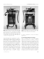
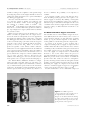
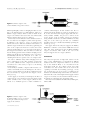
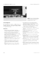
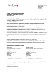
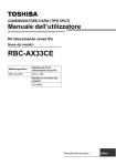
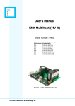
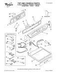
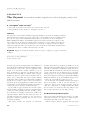
Anaesthesia, 1997, 52, pages 668–672
................................................................................................................................................................................................................................................
A P PA R AT U S
The Oxyvent
An anaesthetic machine designed to be used in developing countries and
difficult situations
R. J. Eltringham1 and A. Varvinski2
1 Gloucestershire Royal Hospital, Great Western Road, Gloucester GL1 3NN, UK
2 Archangelsk Medical Academy, Troytski 51, Archangelsk 163061, Russia
Summary
The Oxyvent is an anaesthetic machine designed specifically for use in the developing world and
difficult situations. It is made up of four components, each of which has, in its own right, already
proved to be of great value in difficult situations. These are the drawover system, the Penlon
Manley Multivent Ventilator, the DeVilbiss Oxygen Concentrator and the air compressor. The
four components are mounted on a simple trolley carrying two oxygen cylinders. The Oxyvent
can be used to provide anaesthesia in the absence of electricity or oxygen or both. It is simple,
robust and easily serviceable. It is versatile and can be used both as an anaesthetic machine in the
operating theatre and as a ventilator in an intensive care unit.
Keywords Equipment; anaesthesia machine, drawover system, compressor, oxygen concentrator,
ventilator.
......................................................................................
Correspondence to: Dr R. J. Eltringham
Accepted: 6 February 1997
In many regions of the world anaesthetics are administered
by health workers with limited training, unreliable supplies
and inadequate and poorly serviced equipment. The
design of an anaesthetic machine suitable for use in
these circumstances is therefore very different from one
intended for use in the UK, for example, where adequate
facilities are taken for granted. Such a machine must be
robust, easy to understand and operate, require minimal
maintenance and be readily serviceable using local skills. It
should also be versatile so that it can be used whatever
anaesthetic agents and equipment are available at the time
and should be capable of functioning if either the supply of
compressed gases or electricity are interrupted [1].
It can readily be appreciated that the modern, sophisticated machines currently used in most hospitals in this
country are totally unsuitable and why attempts to introduce them into developing countries have usually been
expensive failures. When the first fault arises they are
generally discarded and consigned to the graveyard of
anaesthetic apparatus gathering dust in store rooms
around the world [1].
This article describes the Oxyvent, an anaesthetic
668
machine which has been designed specifically for use in
difficult situations. It fulfils all the above requirements and
can make a considerable contribution towards safer anaesthesia in difficult environments. The Oxyvent is made up
of four components each of which has, in its own right,
already proved to be of great value in difficult situations.
These are, the Drawover System [1–4], the Penlon Manley
Multivent Ventilator [5–8], the DeVilbiss Oxygen Concentrator [9, 10] and the air compressor [1, 2].
In the Oxyvent, the DeVilbiss Oxygen Concentrator
has been modified so that it can also function as a
compressor and has been mounted together with the
other two components on a simple metal trolley which
has two shelves, an electrical socket and cradles for two
600-l oxygen cylinders at the rear (Figs 1 and 2).
The Drawover Anaesthesia system
This system enables inhalational anaesthesia to be administered in the absence of a supply of compressed gases,
atmospheric air being used as the carrier gas.
Various forms of drawover apparatus have previously
Q 1997 Blackwell Science Ltd
Anaesthesia, 1997, 52, pages 668–672
R. J. Eltringham and A. Varvinski • The Oxyvent
................................................................................................................................................................................................................................................
Figure 1 The Oxyvent viewed from the front. The Penlon
Figure 2 The Oxyvent viewed from the rear. Cradles contain-
Manley Multivent ventilator is on the upper shelf with the OMV
vaporiser and reservoir tube on the right side. The DeVilbiss
Oxygen Concentrator is on the lower shelf. The oxygen flow
knob is situated below the flow meter in the centre of the
concentrator. Next to this is the oxygen outlet which is connected by tubing to the reservoir tube. On the right of the
concentrator is the compressed air outlet.
ing the oxygen cylinders are on either side of the trolley.
Electrical sockets are situated between the cylinders.
been described [2], but the essential features of each are: a
calibrated vaporiser with a sufficiently low resistance to
allow spontaneous respiration, a means of giving positive
pressure ventilation such as a self-inflating bag or bellows
with a valve to prevent the gas mixture from re-entering
the vaporiser and a unidirectional valve at the patient’s
airway to direct expired gases into the atmosphere to
prevent rebreathing. In the Oxyvent, modifications of
both the Oxford Miniature Vaporiser (OMV) [11] and
the Oxford Inflating Bellows (OIB) [3] are used. The
inspired mixture can be supplemented by oxygen from the
first of the two cylinders delivered to an open-ended
reservoir tube via a T piece upstream of the vaporiser
[12]. The oxygen flow is controlled by a Houtonox
oxygen regulator at either 1 or 4 l.minÿ1 according to
Q 1997 Blackwell Science Ltd
the patient’s requirements as used in the Triservice
apparatus [11].
The Penlon Manley Multivent ventilator
This is a mechanical version of the Oxford inflating
bellows [5]. The driving force required to expand the
bellows can be any gas source at a pressure of at least
140 kPa, such as a standard oxygen cylinder. The second
oxygen cylinder is connected via a regulator to the driving
gas inlet at the rear of the ventilator for this purpose. A
weighted beam attached to the top of the bellows is driven
upwards around a fulcrum by the compressed gas acting
on a linear thruster. This causes the bellows to expand
drawing into it the inspired gas mixture. When it has
reached the required height, as determined by the tidal
volume setting, the weighted beam descends compressing
the bellows and delivering the gas mixture to the patient.
The inspiratory pressure can be adjusted to a maximum of
669
R. J. Eltringham and A. Varvinski • The Oxyvent
Anaesthesia, 1997, 52, pages 668–672
................................................................................................................................................................................................................................................
4.9 kPa according to the compliance of the patient’s lungs
by varying the position of the weight. A handle on the end
of the beam enables the bellows to be operated manually if
the driving gas supply fails.
The ratio of the linear thruster to the bellows has been
set so that the volume of driving gas required is only
1/10th of the minute volume set for the patient [5].
For example, at a minute volume of 6 l.minÿ1 only
600 ml.minÿ1 of the driving gas is required. It is therefore
much more economical than other gas-driven ventilators
[13, 14]. A single 600-l oxygen cylinder when used in this
way can last for 16 h.
When oxygen is being used as the driving force, even
further economies are possible since the oxygen used to
elevate the beam can subsequently be used to supplement
the inspired gas mixture. This is achieved by connecting
the driving gas outlet situated on the side of the ventilator
to the reservoir tube (Fig. 3). In other words, the oxygen is
used twice, first of all to expand the bellows and subsequently to increase the FIO2. Values of 30–40% are
produced regardless of the minute volume delivered,
without the need for supplementation from an additional
source [15]. If oxygen is unavailable to drive the ventilator
then compressed air can be used as an alternative source of
power, either from a compressor or from a cylinder. In this
case of course, the FIO2 cannot be increased by the
addition of the driving gas to the reservoir tube as before
and a separate source of oxygen is needed for this purpose.
The Penlon Manley Multivent Ventilator is simple,
robust and easily serviceable. There are only three controls, tidal volume, respiratory rate and I:E ratio, so that it is
easy to understand and operate. If ether is the anaesthetic
agent in use, an alternative version, in which the electronic
circuit is separated from the gas mixture by a distance of
25 cm to eliminate the possibility of an explosion, is
available.
It is extremely versatile, can be used with any anaesthetic breathing system [5] and does not require a continuous supply of electricity. By utilising a rechargeable
battery incorporated within the casing it can continue to
function for up to 48 h without interruption in the event
of a failure of the electricity supply. It has been thoroughly
tested in a variety of clinical situations and shown to be
reliable [6, 7].
The Modified DeVilbiss Oxygen concentrator
The standard version of the DeVilbiss Oxygen Concentrator (MC44) has been used for many years as a source of
oxygen both for domestic use [16] and in the operating
theatre [9, 10]. Its function depends on the ability of
zeolite granules to absorb nitrogen from compressed air.
It consists of an air inlet, a series of filters and a
compressor which produces a supply of compressed air at
140 kPa. This is then directed into the first of two canisters
containing zeolite, in which the nitrogen is absorbed and
the residual oxygen passed to the patient (Fig. 4). After
<10 s the supply of compressed air is automatically
diverted to the second canister where the process is
repeated and the flow of oxygen continues uninterrupted.
While the pressure in the second canister is 140 kPa the
pressure in the first canister is reduced to atmospheric
pressure, the nitrogen released into the atmosphere and the
granules of zeolite recharged ready for the next cycle. By
alternating the supply of compressed air between the
canisters a continuous supply of oxygen at a concentration
of 90% can be produced at flows of up to 5 l.minÿ1 .
Routine maintenance can be undertaken using local
Figure 3 The OMV vaporiser is
connected directly to the gas inlet port on
the right-hand side of the ventilator.
Oxygen can be delivered from the driving
gas outlet on the ventilator to the reservoir
tube upstream of the vaporiser by the tube
passing in front of the vaporiser.
670
Q 1997 Blackwell Science Ltd
Anaesthesia, 1997, 52, pages 668–672
R. J. Eltringham and A. Varvinski • The Oxyvent
................................................................................................................................................................................................................................................
Figure 4 Schematic diagram of the
standard DeVilbiss Oxygen Concentrator.
skills and principally consists of changing the filters according to the manufacturer’s recommendations. There is a
built-in oxygen analyser which sounds an alarm if the
oxygen concentration decreases below 70%. This usually
indicates that the filters need to be changed.
In the Oxyvent a modification of the standard version of
the concentrator is used (Figure 5). This version provides,
in addition to the oxygen, a source of compressed air
which can be used to drive the ventilator in the absence of
cylinder oxygen. This has been achieved by syphoning off
some of the compressed air before it reaches the zeolite
canisters and diverting it to a second outlet on the front of
the Oxygen Concentrator. This can then be fed directly
into the driving gas inlet of the ventilator via high-pressure
tubing [15]. In this way an alternative source of power is
automatically built into the Oxyvent at no extra cost,
obviating the need for a separate source of compressed air.
In order to eliminate delays when changing from one
source of driving gas to the other, both the oxygen from
the second cylinder and the compressed air from the
concentrator are connected by a T piece to the driving
gas inlet (Fig. 6).
If electricity is available, compressed air from the concentrator is normally used as the driving force in order to
conserve oxygen. In this case the FIO2 is supplemented via
the reservoir tube by oxygen from the oxygen concentrator [15, 17].
If the supply of electricity is interrupted, the flow of
compressed air ceases and the low-pressure alarm sounds
on the ventilator. The second oxygen cylinder is then
turned on to maintain power to enable ventilation to
continue uninterrupted. In this situation the F IO2 is
enhanced from the driving gas outlet as described above.
If, on the other hand, the oxygen supply fails and electricity remains available, the process is carried out in
reverse. In the event of neither oxygen nor electricity
being available anaesthesia can still be administered safely
using air as the carrier gas. In this case ventilation
should be assisted or controlled by manually operating the
bellows [3, 5, 11].
The upper shelf of the Oxyvent supports the Manley
Multivent to which is connected the OMV and reservoir
tube. The lower shelf supports the modified DeVilbiss
oxygen concentrator. The cradle at the rear of the
Oxyvent supports the two oxygen cylinders.
Conclusion
The Oxyvent represents an important advance in the
safety of the administration of anaesthesia in difficult
situations. The four components enable it to be used in
any of the situations likely to be encountered in the
developing world [1]. It is simple, robust and easily
serviceable. It is also versatile and can be used in the
operating room with any breathing system [5], on any
size of patient [7] or it can be used as a ventilator in an
intensive care unit. Most important of all it can continue to
function in the event of interruption in the supply of either
oxygen or electricity or both, situations which are all too
frequently encountered in the developing world.
The Oxyvent is available from Penlon Ltd of Abingdon,
OX14 3PH.
Figure 5 Schematic diagram of the
modified DeVilbiss oxygen concentrator
showing the additional compressed air
supply for the ventilator.
Q 1997 Blackwell Science Ltd
671
R. J. Eltringham and A. Varvinski • The Oxyvent
Anaesthesia, 1997, 52, pages 668–672
................................................................................................................................................................................................................................................
Figure 6 The rear of the Penlon Manley
Multivent ventilator showing both oxygen
and compressed air connected to the
driving gas inlet by a T piece.
Acknowledgments
We acknowledge the assistance of Philip Ottoway of
DeVilbiss Health Care and Craig Thompson of Penlon
Ltd in the preparation of this paper, and Christina Finch
for typing the manuscript.
References
1 Ezi-Ashi TI, Papworth DP, Nunn JF. Inhalational
anaesthesia in developing countries 1. The problem and
the proposed solution. Anaesthesia 1983; 38: 729–35.
2 Ezi-Ashi TI, Papworth DP, Nunn JF. Inhalational
anaesthesia in developing countries 2. Review of existing
apparatus. Anaesthesia 1983; 38: 736–47.
3 Boulton TB. Anaesthesia in difficult situations (3). General
anaesthesia technique. Anaesthesia 1966; 21: 513–45.
4 Farman JV. Anaesthesia and the EMO System. London:
English University Press, 1973.
5 Manley R. A new ventilator for developing countries and
difficult situations. World Anaesthesia Newsletter 1991; 5:
10–11.
6 Tindimwebwa VB, Mijumbi C. Preliminary clinical
experience with the Manley Multivent in Mulago
Hospital, Uganda. World Anaesthesia Newsletter 1992;
7: 5.
7 Eltringham RJ, Khuwaja A. Progress with the Manley
Multivent. World Anaesthesia Newsletter 1993; 10: 6–8.
672
8 Shrestha BM, Amatya R, Basnyat MB, Singh BB,
Lekak BD, Gurung A. The Penlon Multivent in Nepal.
World Anaesthesia Newsletter 1995; 13: 10–11.
9 Fenton PM. The Malawi anaesthetic machine (experience
with a new type of anaesthetic apparatus for developing
countries). Anaesthesia 1989; 44: 498–503.
10 Pederson J, Nyrop M. Anaesthetic equipment for a
developing country. British Journal of Anaesthesia 1991; 66:
264–70.
11 Houghton IT. The Triservice anaesthetic apparatus.
Anaesthesia 1981; 36: 1094–108.
12 Mackie AM. Drawover anaesthetic systems. Anaesthesia
1987; 42: 299–304.
13 Penlon AV 600 Anaesthesia Ventilator. User Manual. Penlon
Ltd, 1996.
14 Penlon Ventilator Series 200. User’s Instruction Manual.
Penlon Ltd, 1996.
15 Eltringham R. Further experience with the Penlon Manley
Multivent ventilator. Its use with the modified DeVilbiss
Oxygen Concentrator. World Anaesthesia Newsletter 1994;
11: 10–11.
16 Cooper CB, Waterhouse J, Howard P. Twelve year clinical
study of patients with hypoxic cor pulmonale given long
term domiciliary oxygen therapy. Thorax 1987; 42:
105–10.
17 Jarvis DA, Brock-Utne JG. Use of an oxygen concentrator
linked to a drawover vaporizer (anesthesia delivery system
for underdeveloped nations). Anesthesia and Analgesia 1991;
72: 805– 810.
Q 1997 Blackwell Science Ltd