1
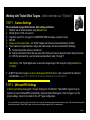
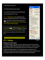
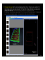
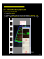
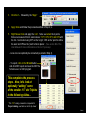
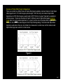
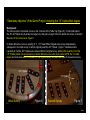
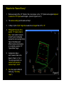
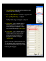
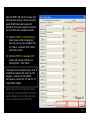
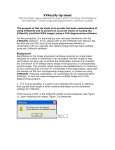
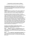
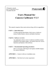
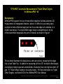
TIP SHEET: Automatic Measurement of Triplet Offset Targets
for iWitnessPROTM V2
Background:
Background:
iWitnessPRO supports the use of triplet offset targets to facilitate automatic 3D
measurement of untargetable features, where it is difficult to accurately place
a single red retro-reflective target (such as the curved edges of a tabletop, or a
kitchen countertop). The triplet offset target design is straightforward; the tip
of the triplet offset designates the point of interest, as shown in Figure 1.
Figure 1
This tip sheet illustrates the dialog boxes, and user actions, measuring the edges
of a curved Table Top. In addition to measuring with the .25” dot triplet offset targets,
a secondary network was also accomplished, illustrating howFigure
one might
1 use both .25”
and .15” Triplet Offset Targets in the same project. For more information on Triplet
Offset Targets, visit Section D3 of the iWitnessPRO User Manual.
©2010 All Rights Reserved, DeChant Consulting Services – DCS Inc & Photometrix
www.iwitnessphoto.com
Slide 1
Working with Triplet Offset Targets - (often referred to as “Triplets”)
STEP 1. Camera Settings
We recommend using a DSLR Camera, with settings as follows:
1. “Manual” set on the dial and also using Manual Focus
2. Shutter Speed 1/125th of a second
3. *Aperture: about F13 (the goal is to UNDEREXPOSE the images a couple F-stops)
4. ISO 400
5. Always use the camera flash – the Triplet Targets and codes must be illuminated by the flash
6. If your camera to target distance is only a few meters away, then we recommend the following:
6a. Temporarily put the camera in “autofocus”.
6b. Depress the shutter button half-way down (this will focus the lens making the triplets sharply focused)
6c. With the camera still on, use the camera as described in step 1 through 5
Alternatively, if the Triplet targets are in a camera-to-target range of 2m to say 6m, simply set the focus
to “infinity”
7. ALWAYS shoot the images in a mix of Landscape and Portrait shots – this is required for the camera’s
Scale distance A | B
self calibration - (see Part C, Section C2 of the User Manual for more information)
STEP 2. iWitnessPRO Settings
In the Project Settings dialog (Edit + Project Settings) the Tick Mark for “Triplet Offset Targets” must be
selected to ensure iWitnessPRO automatically measures triplet offset targets. Refer to Figure 2, for the
proper settings. Note: the tick mark for the .25” Target configuration.
•You can optionally ‘open up’ the shutter (to about F8) to allow more light, to manually measure Natural Features as well. This tip sheet was designed for
the optimum exposure of Triplet Offset Targets, thus the reason the imagery appears “dark” or underexposed.
Slide 2
i) ‘Red Targets’ must be selected;
ii) ‘Find triplet offset targets’ must be selected;
i)
iii) The physical size of the targets on the triplet offset targets
must be selected (either 0.15” or 0.25”);
iv) NOTE: Scale MUST be set for an iWitnessPRO network
before the triplet offset feature will function correctly. Optionally,
scale via retro-reflective codes can be selected in the Project
Settings dialog. For more accurate results, a scale bar (or scale
bars) can be measured within the project.
We recommend scaling using scale bars after running the “R++”.
Once the scale is applied, (Right Click “Set Scale…”) proceed to
the 3D Points List and click the “Process” button. The Triplet
Offset Points are now presented in the 3D Points List and 3D
View.
STEP 3. Field Work
Setting up the Triplet Targets
ii)
iii)
Figure 2
To use triplet offset targets, simply place any number of them within the scene of interest at the time
of photography and iWitnessPRO will automatically measure them during the R++ process. Triplet offset
points are shown in dark blue in the images and the 3D List, and in red in the 3D View. Each time a
photogrammetric bundle adjustment is run, the triplet offset points are recalculated in 3D, and
thus they are only temporary and not saved in the project file. They can, however, be exported via the 3D
points dialog for example in .DXF format for consideration within third-party CAD software.
Slide 3
1.
Photograph the project with the camera settings described in Step 1. Figure 3 used a quantity of 12
coded targets, and two scale bars along with 100 Triplet Offset Targets defining the curved geometry
(edges) of the Table Top. Note how the images are taken in a “ring pattern” around
the table top. The camera was approximately 1.5 to 2.5 meters from the triplet targets. 10 images were
used, but 20 were originally imaged. It is always better to take more photos than less.
Table Top
Figure 3
Slide 4
STEP 4. iWitnessPRO software (computer) work
2.
Import the images into iWitnessPRO
2a. Follow the Step 2 settings.
2b. Open one of the images and place the cursor within the image and click the keyboard “Q” key
(see Figure 4) and click the Optimize! button. Click OK when complete, to close-out of the dialog box.
Image Scanning & Auto
Measurement settings
(Q-key)
Then, it is finished… ;-)
Figure 4
Slide 5
3.
Click the R++ followed by the “Begin”
4.
Apply Scale and follow the process described in Step 2, vi.
5.
Right Mouse Click and apply the 3-2-1. Note: we named the 4 points
that were measured from 2 scale bars as: *CP1, CP2, CP3, and CP4 with
the 3-2-1 conducted using CP1 as the “origin”, CP2 as the “point to define
the axis” and CP3 as the “point to fall on plane”. (See section B4 of the
User Manual for more information on the 3-2-1 process).
- Lines can now optionally be connected (as noted in Step 3).
- To export, click on the 3D List button
and click DXF export and save the DXF file
for later use in a CAD program.
This completes the process
steps. Now, let’s look at
optionally “adding” some
of the smaller .15” dot Triplets
in the following slides…
* The “CP” naming convention is required for
Project Linking, used later on in this tip sheet
Slide 6
Overview of Triplet Offset Target Configurations:
There are currently two different sizes of triplet offset targets available; small and medium. Small triplet
offset targets have 0.15”/3.8mm targets (overall length 1.425”/36.2mm); and medium triplet offset
targets have 0.25"/6.35mm targets (overall length 2.875”/73.0mm). A larger Triplet will be available in
a future release. Triplets are illustrated in Figure 5. Different sizes of triplet offset targets cannot be
mixed within the same bundle adjustment (i.e., project), but the size of the triplet offset targets can be
different to the size of the coded targets via the Project Settings dialog. The small-sized triplet offset
targets are useful when there is a lot of detail to be measured in a small area, and the medium-sized
triplet offset targets are useful for normal scenes.
Figure 5
Slide 7
“Secondary objective” of the Demo Project: including the .15” triplet offset targets
Background:
The demo project incorporated curves on the 4 corners of the Table Top (Figure 6). In this initial project,
the .25” dot Triplets are physically too large to try and place enough of them to define the curves, as noted in
the areas of the red arrows in Figure 6.
To better define the curves, a quantity of 11, .15” Triplet Offset Targets were survey independently,
subsequent to the initial survey, of which originally used the .25” Triplets. Figure 7, illustrates where
a quantity of 3 of the .25” Triplets were removed after the original survey, with another quantity of 3 of the
.15” Triplets placed in a second survey to better define the curve with more points. NOTE: the 12 coded
targets and scale bars were not moved from the original survey, and were also used in the second survey.
.25” Triplets
Remove
.15” Triplets
Remove
Remove
Initial Survey
Figure 6
Second Survey
Figure 7
Slide 8
Steps for the “Second Survey”
1.
Remove enough of the .25” Triplets in the curved areas, so the .15” Triplets can be applied adjacent
to where the .25” Triplets were imaged – (noted in Figure 6 and 7).
2.
The camera settings are the same as Step 1.
3.
In Step 2, iii) the Triplet Target Size needs to be changed from .25” to .15”.
4.
Photograph the areas of the
applied .15” triplets similar to
Step 3 (one needs to acquire
at least 5 good overlapping
perspective camera angle shots).
Figure 8 illustrates eight
different camera observations
on a randomly selected .15”
Triplet Offset Target.
5.
6.
Complete the Step 4
work, however there is No
Need to “Scale” or “3-2-1”.
The only requirement is to
name the CP points the
same as Step 4, item 5.
Save the project a different
name (e.g. “Secondary
.iwpro”)
CP3
CP4
CP1
CP2
Figure 8
Slide 9
7.
Close out of the project (assure there aren’t any projects (i.e. iwpro’s)
minimized in the WindowsTM task bar)).
8.
Click on the iWitnessPRO short-cut and start a new project and select
File + Import Projects for Linking… - see Figure 9.
The Project Linking dialog is now displayed - see Figure 10.
9.
Click the Import… button as indicated in Figure 10.
NOTE: the project “Network one (1)” you import
will be the initial project accomplished. For this tip
sheet, we named the initial project “Table Top.iwpro”.
Figure 9
Click for the noted Step 9
Click for the noted Step 10
10. Click the Import… button as indicated in Figure 10.
NOTE: the project “Network two (2)” you import
will be the second project accomplished. For
this tip sheet, we named the second project
“Secondary.iwpro”.
Figure 11 illustrates the coordinate transformation result.
The Table Top.iwpro and the Secondary.iwpro are now
in the same coordinate system, ready to export as a DXF
file to a third party CAD program.
Figure 10
Slide 10
Note the “RMS .006” (fit) in the upper right.
With precision scaling, a decent consumer
grade DSLR camera and a good self
calibration, this result is typical of a project
the size of the demo example networks.
11. Click the “STEP 2 – Perform Linking”
button (lower middle of dialog box).
Note: as soon as you accomplish this,
the “Step 3 – Generate .DXF” button
will become ‘active’.
12. Click the “STEP 3 – Generate .DXF”
button” and save the .DXF to your
working folder. Click “Close”.
The project is now complete. Figure 12 & 13
illustrate the results of the work in a CAD
program. A series of 3-Point ARCS
were used to connect the .25” and the .15”
Triplet Offset Targets.
NOTE: one can also compress the Z-axis
to zero (0) in the iWitnessPRO .DXF export
options dialog box if the Triplets are being
used on a planar surface (XY Plane).
Figure 11
Slide 11
Figure 12
Slide 12
Figure 13
Slide1313
Slide
Final Notes -- Tips for use of Triplet Offset Targets:
i) Do not place triplet offset targets too close to coded targets or single feature points, as they will function more
consistently if left with some space (approximately 1-diameter of the overall size) surrounding them.
ii) Triplet offset targets should be spaced at least 2.5cm/1” apart from each other.
iii) If a triplet offset target is missed by iWitnessPRO, it is possible to manually measure (i.e. force) it in the 3D
view. Select the three points that form the missed triplet and press the ‘O’ key (Letter ‘O’) on the keyboard. This
will identify the triplet offset target and generate the offset point. The three points forming the triplet offset target
must have been calculated correctly for this to work.
iv) If iWitnessPRO seems to miss a large number of triplet offset targets in a survey, it may be useful to select
Maximum Pts in the Image-Scanning & Auto-Measurement settings dialog, before rerunning a bundle
adjustment.
It is also possible to connect lines between offset points, though once again these are only temporary and it is
important to note that running the bundle adjustment will remove lines between offset points. Therefore, lines
should only be connected between offset points once all other processes have been completed, and just prior
to exporting a .DXF file. iWitnessPRO will give a warning message for the first line that is measured between
offset points, giving an option to force the bundle adjustment to be “turned off” to avoid accidentally removing
lines between offset points (see Figure 14). Similarly, iWitnessPRO will give a warning message before turning
the bundle back on (see Figure 15).
Figure 14
Figure 15
Slide 14