1
myHouse
3D-HOME DESIGN
For do-it-yourself Architects
User’s Guide
DesignSoft
END-USER LICENSE AGREEMENT FOR DESIGNSOFT
SOFTWARE
IMPORTANT-READ CAREFULLY: This DesignSoft End-User License Agreement ("Agreement") is
a legal agreement between you (either an individual or a single entity) and DesignSoft Corporation
for the DesignSoft software accompanying this Agreement, which includes computer software and
associated media and printed materials, and may include "online" or electronic documentation
("SOFTWARE PRODUCT" or "SOFTWARE"). By opening the sealed packet or by downloading or
installing the SOFTWARE PRODUCT or exercising your rights to make and use copies of the
SOFTWARE PRODUCT, you agree to be bound by the terms of this Agreement.
If you do not agree to the terms of this Agreement, promptly return this package to the place from
which you obtained it, or in case of a download, delete the downloaded file(s) and uninstall the
product from your computer(s).
SOFTWARE PRODUCT LICENSE
The SOFTWARE PRODUCT is protected by copyright laws and international copyright treaties, as
well as other intellectual property laws and treaties. The SOFTWARE PRODUCT is licensed, not
sold.
1. GRANT OF LICENSE. DesignSoft grants to you a nonexclusive right to use the SOFTWARE
PRODUCT on a single computer unless otherwise indicated on the invoice ccompanying this
product. You must pay for additional copies of the software if more than one copy will or may be
running at the same time on one or more computers. You may not rent, sell, lease, sub-license,
time-share or loan the software to others.
2. COPYRIGHT. All title and copyrights in and to the SOFTWARE PRODUCT (including but not
limited to any images, photographs, animations, video, audio, music, text, and "applets,"
incorporated into the SOFTWARE PRODUCT), the accompanying printed materials, and any
copies of the SOFTWARE PRODUCT, are owned by
DesignSoft or its suppliers. The SOFTWARE PRODUCT is protected by copyright laws and
international treaty provisions. Therefore, you must treat the SOFTWARE PRODUCT like any
other copyrighted material except that you may either (a) make one copy of the SOFTWARE
PRODUCT solely for backup or archival purposes, or (b) install the SOFTWARE PRODUCT on a
single computer (except as described in section 1) provided you keep the original solely for backup
or archival purposes,.
3. OTHER RESTRICTIONS. This Agreement is your proof of license to exercise the rights granted
herein and must be retained by you. You may not reverse engineer, decompile, or disassemble the
SOFTWARE PRODUCT, except and only to the extent that such activity is expressly permitted by
applicable law notwithstanding this limitation.
LIMITED WARRANTY NO WARRANTIES. DesignSoft expressly disclaims any warranty for the
SOFTWARE PRODUCT. The SOFTWARE PRODUCT and any related documentation is provided
"as is" without warranty of any kind, either express or implied, including, without limitation, the
implied warranties or merchantability, fitness for a particular purpose, or non-infringement. The
entire risk arising out of use or
performance of the SOFTWARE PRODUCT remains with you.
NO LIABILITY FOR CONSEQUENTIAL DAMAGES. In no event shall DesignSoft or its suppliers
be liable for any damages whatsoever (including, without limitation, damages for loss of business
profits, business interruption, loss of business information, or any other pecuniary loss) arising out
of the use of or inability to use this DesignSoft product, even if DesignSoft has been advised of
the possibility of such damages. Because some states/jurisdictions do not allow the exclusion or
limitation of liability for consequential or incidental damages, the above limitation may not apply to
you.
MISCELLANEOUS
Should you have any questions concerning this Agreement, or if you desire to contact DesignSoft
for any reason, submit your question at www.designsoftware.com under Technical Support or
please write to:
DesignSoft
myHouse
Contents
10
Chapter I Introduction
1 Inside myHouse
11
Chapter II Installation
14
1 System
Requirements
14
2 Installing the
Software
14
3 Software key
authorization
15
20
Chapter III The Basics
1 Looking at the
myHouse Window
20
Drawing Area
Menu Bar
Toolbars
Coordinate Line
Function keys
Key combinations
20
21
21
23
23
24
2 Understanding
Distances in
myHouse
26
The Cartesian Coordinate System
Manually Entering Coordinate Values
Using Zoom
3 Working With
Windows
26
27
27
27
Common Windows Commands
Using the Mouse
27
28
4 Entering Data
29
5 Handling Files
29
6 Viewing Designs
30
7 Using Help
31
myHouse - 5
myHouse
34
Chapter IV Quick Start
1 Draw a slab
34
2 Draw exterior walls
35
3 Draw interior walls
35
4 Draw doors
36
5 Draw windows
37
6 Insert symbols
38
7 Add a roof
40
8 Save your design
40
9 View in 3D
41
10 Add dimension lines
42
11 Add text
43
12 QuickHouse
44
Chapter V Designs
46
1 Creating Building
Elements
46
Using the Keyboard to Enter Elements
Slabs
Columns
Walls
Doors, Windows
Stairs
Rails
Symbols
Photo Library
Roofs, Chimneys, Skylights, Dormers
2 Creating Multiple
Stories
46
47
49
50
52
52
54
54
55
56
57
Using Layering to Align Levels
59
3 Modifying Building
Elements
59
Slabs
Walls
Doors, Windows
Stairs
Rails
Symbols
60
60
61
61
62
62
myHouse - 6
myHouse
Roofs
Columns
62
62
Chapter VI Enhancements
64
1 Drawing Primatives
64
2 Drawing Dimension
Lines
65
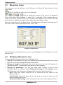
3 Measuring Areas
67
4 Modifying
Dimension Lines
67
5 Using Grids
68
6 Changing Units
69
7 Texture setting
69
8 Bill of Materials
69
72
Chapter VII Views
72
1 Viewing in 2D
Zoom
Foils - Layering
72
73
73
2 Viewing in 3D
Saving the 3D View
Printing the 3D View
DreamScape
Ray Tracing
Panoramic Images
How to create panoramic images
3D MovieMaker
76
76
77
77
78
78
79
82
Chapter VIII 3D Modeler
1 The Views
82
2 The Toolbar
83
3 The Menu
84
4 Helpful Hints
84
5 Creating a Symbol
85
6 Advanced
Techniques
89
Chapter IX Hints & FAQ’s
92
myHouse - 7
myHouse
1 Frequently Asked
Questions
92
2 Hints
95
97
Index
myHouse - 8
Chapter
I
Introduction
1 Introduction
Have you ever dreamed of designing your own home? Are you ready to talk to an
architect about transforming the ideas in your head into a house or new addition? Then
myHouse is the right tool for you.
With myHouse, exploring different design ideas is easy and enjoyable. With a few
clicks of the mouse, you can fill a floor design with walls, windows, stairs, plants - your
imagination is your only limit. Your designs will awe your friends and family and can be
accurate enough to show an architect exactly what you want to build.
If you like, you can start with one of the home designs provided by myHouse.
Changing elements in a completed design is an excellent introduction to the power of
myHouse. Experiment until you become familiar with how easy it is to both visualize
and modify elements of a design. Take the time to switch back and forth from 2 to 3
Dimensional views, zoom in for a closer look, move a couch around, or drag a wall with
the mouse.
Starting a new design is also easy - no matter how simple or how grand the house is
you want to design. The basics come first, such as the foundation and walls. Using
the icons and the drop-drown menus, you can draw and even modify these elements in a
minute or two.
You will find that the time-consuming part of house design is making up your mind.
myHouse puts so much flexibility at your fingertips that you will be tempted to tinker
and to dream for hours at a time. Exactly what shape and size, for example, is the perfect
den for relaxing on Sunday afternoons? Are we talking an Olympic-sized pool in the
backyard, or a more intimate setting screened with plants?
When the skeleton of the plan is ready, you select doors and windows for each room
from an expandable library. Connect different floors with stairs and finish them off
with a variety of rails and finishes to suit your every whim. Now you are ready to fill
your rooms with appliances and furnishings. Once you select the types and sizes you
want, you can move them around the rooms until you are satisfied that you have found
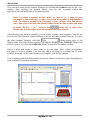
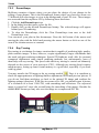
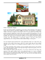
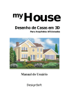
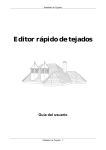
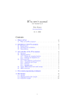
the best arrangement. Then using the 3D view and the photorealistic Raytracing
feature the end result could be a design like the one shown on the next page.
myHouse - 10
Introduction
Photorealistic 3D rendering of a myHouse design.
1.1
Inside myHouse
The myHouse product includes the folowing:
Menu and Icon-Driven Drawing Program: This software allows you to
design the house of your dreams quickly. You can execute the necessary commands either with a mouse or from the keyboard. Online Help is available when
needed.
Pre-Drawn Building Elements: The elements you use to create a design have
been pre-drawn by professionals and compiled in libraries. You pick an element from a library, set its parameters (such as size and color), and place it in your
design.
Registration Card: Fill out and send in this card to receive free technical
support, notice of upgrades, and other special offers.
Modeler Software: Use this functionality to create or modify your own
symbols and libraries.
Stair Designer: With the new Stair Designer it is very easy to design and place
stairs in your design You can use the various templates or start from scratch and
design your own custom stairs.
Roof Designer: The myHouse Roof Designer makes it very easy to create and
place a roof on your design. The Roof Designer automatically generates roofs or
allows you to manually create or edit roofs and view the results in 3D.
myHouse - 11
Introduction
Terrain Designer: You create the topography of the terrain by putting down
the corner points and the other defining points (put down by pushing Insert) and
defining their relative height to each other. This way you create a terrain for 3D
view.
User’s Manual: 9 chapters and two appendices to help you along the way.
myHouse - 12
Chapter
II
Installation
2 Installation
This chapter outlines the recommended system setup for installing myHouse. The
second section provides the few easy steps required to load the software.
2.1
System Requirements
The minimum suggested configuration of hardware and software for running
myHouse is the following:
-
IBM or IBM compatible PC with 486DX
-
1 GB of RAM (1GB or more suggested)
-
300MB of hard disk space (400MB or more suggested) Mouse or Windows
compatible pointing device Microsoft Windows 9x/ME/NT/2000/XP/Vista
20X CD-ROM drive
2.2
Installing the Software
Check the list of requirements in the previous section before you install myHouse. To
install myHouse:
1. To begin the installation simply insert the CD into you CD-ROM drive.
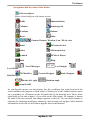
2. The Setup Program will start automatically if the Auto-Run function of your
CD-ROM has been enabled (Windows-Default). If not, select Start/Run and then
type:
D:SETUP (where D represents your CD-ROM drive.)
(If your CD-ROM drive is identified with another letter, type that letter instead.)
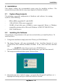
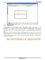
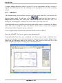
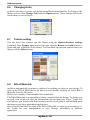
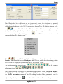
3. The setup screen shown below opens. Click on Next.
4. Check the target drive default setting (c:\program files\designsoft\ myHouse vn\ ).
Highlight the setting and type a different location if desired.
myHouse - 14
Installation
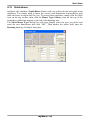
5. Select a typical, compact, or custom installation. A description of each is
provided. Most users should choose “typical.”
6. Select a program folder name. The default name is myHouse vn.
7. Check the settings summarized by the installation program. If acceptable, click the
Next button. Insert the remaining disks when prompted.
8. Once Setup is complete, click Finish.
Your myHouse is now installed. To access the program, go to Start / Programs /
myHouse for Windows / myHouse.
2.3
Software key authorization
In order to run this program, you must receive authorization from DesignSoft.
When you first run the program, a message box appears showing your initial
authorization status. If you do not receive authorization, you are normally limited to 31
sessions to try the program.
At the end of the trial period – but preferably as soon as possible – do the following:
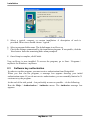
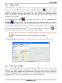
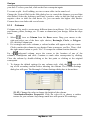
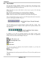
Run the Help / Authorization / Authorize menu. The Authorize message box
appears:
myHouse - 15
Installation
If you have received your program with a 16 digit Order number you can authorize
your program in 3 simple steps described in the dialog box above.
It may be that your firewall does not allow your program to connect to the Internet. In
this case you will get the following messages
If you are connected press OK. The following dialog appears:
Press Yes. Your Site Key will appear in a browser. Copy and Paste this into the
Authorization dialog of your program.
If you do not have an Order number, or it does not work for any reasons or you do
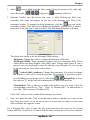
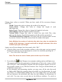
not have Internet connection, then click on the Other tab on the top of the dialog box.
The Other page of the Authorize message box appears:
myHouse - 16
Installation
This dialog shows your personal Site code, which identifies your computer.
Record and send your Site Code and your Order number to DesignSoft by email or
using the given web address. Always use Copy and Paste when you need to copy these
information from one field into another.
If you have received the program on CD, the Order number is provided with the CD. If
you receive the program as download it should be included in the email containing the
download link.
Note, that if you click on the email address above, your default email
program starts using an initial email template, that already includes both
the Order number and the Site key.
If you prefer, you can click on the http://www.designsoftware.com .com address and
select Registration on top of the screen, where you can enter the necessary information.
Whichever option you choose, make sure you give us your
Site Code
Order Number and
your email address
so that we can send you your authorization code (site key).
If you contact us by email or via the web, you will shortly receive an acknowledgement
of your transaction by email. If you haven’t received this acknowledgement very soon,
perhaps you mistyped your email address, so you should re-send the information.
Within a few working days, we will send you your site key by email.
When you receive your Site key, run the Authorize menu again, enter the Site key
into the Site key field, and press OK.
myHouse - 17
Installation
If you want to move your authorized program to another computer, use the commands
“Transfer using removable media” or “Transfer using Internet” from the Help /
Authorization menu. The default password of these commands is
ProgramProtection. For more information see the Help of the Authorization dialog
and check Transfer License.
myHouse - 18
Chapter
III
The Basics
3 The Basics
This chapter describes some fundamentals you need to start using myHouse for
Windows quickly and easily. These include:
Looking at the myHouse window
Understanding distances in myHouse
Working with Windows
Entering data
Handling files
Viewing designs
Using help
3.1
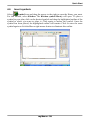
Looking at the myHouse Window
To open myHouse in Windows, click the Start button, select Programs, then myHouse
for Windows, then myHouse. You will then have access to the myHouse drawing
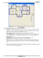
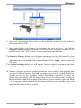
screen. There are four elements on this screen, as shown on the next page.
3.1.1
Drawing Area
This window is where you draw, edit, and view your designs. Tasks are
accomplished by a few clicks of the mouse and movement of the cursor. Note that to
enter elements, you have the option of clicking and holding down the left mouse button
as you drag the mouse. You may be familiar with this approach from working with
other Windows programs.
myHouse - 20
The Basics
3.1.2
Menu Bar
The menu bar contains nine options. Click on an option to see the drop-down menu
associated with it. For example, clicking on Draw opens a menu containing everything
you can insert into a design.
One way to move around myHouse quickly is to click (or drag) the mouse through a
series of menus. Menu commands followed by an arrow open sub-menus. Commands
followed by ellipses (...) open dialog boxes. Click the mouse through the menu series.
Continue until you reach the final menu item you want.
Note: that you can also pull down the menu associated with any option on
the menu bar by pressing ALT-key, where “key” is the underlined letter in
the name (such as F for File).
Note: The drawing area shows one floor, or level, at a time. When you
open a new file, the drawing area shows Floor-0, by default. The name of
this level appears in a tab at the bottom of the drawing area.
If you add additional levels, you will see more tabs on the bottom of the
drawing area. Click on the tabs to move between floors.
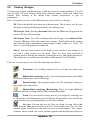
3.1.3
Toolbars
Another way to move around myHouse quickly is to click on the toolbar buttons. There
are two levels of buttons: those in the toolbar across the top of the screen, and those
running down the left side of the screen. The top-level buttons include those shown
below.
Note: To check the name of a tool, move the mouse over the button. A tool
myHouse - 21
The Basics
tip appears with the name of the button.
Select an object
Move selected objects with cursor arrows
Walls
Dimension lines
Columns
Drawing tools
W indows
Redraw
Doors
Slabs
Zoom to Extents, Window, Last, 2D Air view
Roofs
3D External view
Stairs
3D Internal view
Symbols
3D Movie Player
Rails
Help
Level Manager
Level height
Level Name
3D Modeller
Roof Designer
Rotate left, right
Terrain Designer
Stair Designer
Rotation angle
Snap On/Off
As you drag the mouse over the primary bar, the coordinate line at the bottom of the
screen indicates the purpose of each button. Clicking one of the toolbar buttons opens
up a secondary set of buttons on the left hand side of the drawing area. These relate
specifically to the task at hand - if you click on the Slab button, for example, a button
for each of the two possible slab shapes appears to the left. You use these buttons as
shortcuts for inserting, modifying, enhancing, and viewing your designs. More detailed
information on the role of each button appears later in this manual.
myHouse - 22
The Basics
3.1.4
Coordinate Line
The line directly under the drawing area is the coordinate line. Look in this line for data
about the positioning of design elements.
x and y: myHouse defines the position of the cursor on the screen through a
coordinate system (see “Manually Entering Coordinate Values” coming up
in this chapter). The y value defines the amount of movement up and down
relative to a fixed point, and the x value defines the amount of movement
sideways. Use these values when positioning design elements.
d (Length): Length data is provided only for walls, lines, etc.. After you click to
define the first endpoint of a wall, the distance the cursor travels from that
point is shown here.
Angle: If you are inserting a wall or lines, etc., its angle is indicated here.
Origin Placement: Absolute/Relativ Press F5 to toggle between absolute and
relative placement of the origin of the coordinate system. Absolute means
that the origin remains at the lower-left of the drawing area. Relative means that
the origin moves to the first endpoint of each new design element, as you anchor
it.
Messages: Information about the current action is displayed to the left on the
coordinate line.
3.1.5
Function keys
Use function keys or key combinations to change between units or states, or to perform
specific operations. The function keys are the following:
F1
Help.
F2
Automatic magnifier: an area of approximately one square meter around the
drawing pen or selection arrow will be magnified to the size of the whole design
window. Press F2 again to return to the original scale.
F3
Setting step distance: In the default setting, the software allows you to move
your cursor in millimeters. Press F3 to change into centimeters. Pressing F3
again returns the units of measurement to millimeters.
F4
Zeroing coordinates and relocating the relative coordinate system: The
coordinates can be seen at the bottom of the design window. To zero the
coordinates, press F4. The origin of the coordinate system will be relocated to
the cursor's current position, indicated by the appearance of a small red cross.
The elements are then re-matched. Most functions (e. g. drawing new walls) will
myHouse - 23
The Basics
allow for this option, treating the given point as a new origin when removing the
cursor. Thus, after selecting the starting point for a new wall, the second point
will be represented in the coordinate system relative to the first one. Pressing F4
to specify a new origin for the coordinate system.
Note: If the Snap function is on, pressing F4 also invokes a re-matching of
elements, readjusting the crosshairs to the element which is within the
range specified in the Snap adjustments.
Changing between the absolute and relative coordinate-system Press F5 to
switch between coordinate-systems. The origin within the absolute
coordinate-system is the upper left corner of the design window. It is not
advised to begin your project from the absolute zero point. At the beginning of a
new project, the software offers an area of 30.000 by 30.000 cm as the site to
start your project. You are able to create your project in an area extending
approximately 500 meters in both directions.
You can easily return to the absolute origin point by using the scroll bars.
Redraw screen
F5
F6
3.1.6
Key combinations
Key combinations
Shift, CtrlHolding down Shift or Ctrl during editing allows you to introduce
new elements at an orientation in increments of 45 degrees (0, 45, 90).
Space
When drawing a wall, pressing Space modifies its thickness.
Pressing Space also toggles between superimposed elements to assist in
selecting them.
The key combinations for all functions that can be accomplished with
shortcuts are listed next to the function names in the various menus.
File menu:
Ctrl+F3
Ctrl+F2
Ctrl+P
Alt+F4
Open
Save
Print
Exit
Open a project
Save a project
Print the contents of the active window
Close the program
Edit:
Alt+BkSp Undo
Shift+Alt+BkSp
Redo
Ctrl+X
Cut
Ctrl+C
Copy to clipboard
Ctrl+V
Paste from clipboard
Ctrl+Del
Delete
Ctrl+A
Select all
Ctrl+N
Select next
Ctrl+S
Deselect all
myHouse - 24
The Basics
View menu:
Ctrl+F
Foils...
Shift+F
Level foils
Ctrl+G
Grid on/off
Ctrl+W,E,L,D,Z,+,- Zoom options
myHouse - 25
The Basics
Options menu:
Ctrl+O
Orthogonal editing on/off
3.2
3.2.1
Understanding Distances in myHouse
The Cartesian Coordinate System
myHouse uses a Cartesian coordinate system to help you locate exact points while you
are drawing and to measure distances accurately. This means that the program defines
the position of the cursor relative to the origin point of an x,y axis. Touch the screen
with your finger. Think of that point as the origin, or center, of an imaginary x,y
axis. Any point above your finger has a positive y value; any point below your finger
has a negative y value; any point to the right of your finger has a positive x value; and
any point to the left of your finger has a negative x value.
When you begin a design, the origin of the coordinate system (0,0 point) is by default
placed at the lower left corner of a large drawing area (32000'x 32000' or
10000x10000m). By default, the drawing window displays only part of that area (130'x
80' or 40x25m, depending on screen resolution). You can use the scroll bars or the
Zoom function (outlined later in this chapter) to move around the drawing area.
If you press F5 for absolute placement of the origin, the origin moves to the lower- left
corner of the drawing area. In contrast, if you toggle back to relative placement by
pressing F5, the origin will move to the first endpoint of any element you insert.
You can also manually set the placement of the origin with the F4 key. Place the
cursor where you want the origin to be and press this function key.
How do you use the Cartesian coordinate system to help you design your home? With
the x,y axis, you can precisely indentify the position of any point in the drawing
window. As a result you can ensure that:
The endpoints or cornerpoints of two building elements coincide exactly. A building
element is drawn with the exact length and angle required. Design elements are
correctly placed relative to each other.
Another function in myHouse provided for aligning building elements is the
snap-to-grid. This grid is represented by light blue dots in the drawing window. You
can have the endpoints of building elements snap to the grid points when you draw
them. You can, of course, change the size of the grid. This function is explained in
more detail later in this manual.
myHouse - 26
The Basics
3.2.2
Manually Entering Coordinate Values
Besides clicking and moving the mouse to insert a building element, such as a wall, you
can manually enter specific coordinate values for that element. For example, let’s say
you have clicked the mouse to anchor one endpoint of a wall. Now, hit the “X” or “Y”
key on your keyboard.
Type a value for one or both coordinates and hit “Enter.” The wall is drawn to the
dimensions you chose. Hit “Enter” again to anchor that second endpoint. Moving the
mouse before you hit “Enter” the second time will change the coordinates of the second
endpoint.
Note: If you move the cursor after you anchor the first endpoint of the wall,
the x and y values of the cursor position will not be added to those you
type in the Coordinates box.
3.2.3
Using Zoom
Using the Zoom commands from the View menu, you can increase or decrease the
amount of space represented within the drawing manual. For example, if you choose
Zoom Out / Ctrl - , your plan will become smaller and you’ll see more of the drawing
area. You can continue to draw and modify your design in this zoomed view.
If you have a scroll wheel on your mouse (and it is in standard Windows mode), it can
be used to magnify or scale down some elements of your project.
3.3
Working With Windows
If you are familiar with other Windows programs, most of the commands under the
File, Edit, and Window menus in myHouse need little explanation. For help, see your
Windows documentation. Some myHouse-specific aspects to these commands are
noted in the following descriptions.
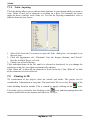
3.3.1
Common Windows Commands
From the File menu
New: Use this command to open a new, blank drawing window. Remember to save
any project you are closing if you want to.
Open: By default, the Open command looks for files in the Project subdirectory, as
defined in install:
(c:\myHouse\project)
myHouse files carry the extension .myh; this extension is selected by default in the
Open dialog box. To open files from earlier versions of myHouse, you’ll need to
change the “Files of type” in the Open dialog box.
Close: Use this command to close the project.
Save and Save As: By default, files are saved with an .myh extension. When saving
a new project for the first time, use Save As. When saving your work on a project as
myHouse - 27
The Basics
you go along, use Save.
Print: Use this command to set printing options and then print your 2D designs.
You can choose to print the entire drawing, or only what appears in the current
drawing area. You can also select from a wide range of scale options as well as
other options to enhance your printout.
Export: Use this function to save projects as .dxf extension files. You can then
import your plan into AutoCAD for plotting.
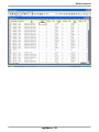
Bill of Materials: Use this command to open the automatic bill of materials
spreadsheet. A more detailed explanation of the Bill of Materials is covered later in
Chapter 6.
From the Edit menu
Undo: Use this command to erase work you have just performed. The Undo
command is unlimited so you can erase as many elements or commands as you
have performed in a work session, in reverse order.
Redo: This command will redo any work that was just undone. Like, Undo, this
command is unlimited.
Cut, Copy, Paste: Select a design element or elements, and then choose one of these
commands. Anything you select with the Cut command is copied to the clipboard.
If you then choose the Paste command, a rectangle appears on the screen. Move
the rectangle with the mouse and click to anchor. The cut material reappears.
Delete: Select a design element by clicking the Pointer icon and then clicking
on the element. Once that element is highlighted, use this command
to delete the element.
Select All: This command selects all the design elements in the drawing window
. You can now perform editing commands on these elements as a block.
Note: You can also select a group of design elements by clicking the
Pointer icon and clicking and dragging to create a selection box. All
elements completely within the box will be highlighted.
3.3.2
Using the Mouse
Using the mouse to perform the commands in myHouse is the fastest way to create
your design. Much like other Windows programs, use the mouse to move the
cursor in myHouse. Click and drag symbols to their new positions, click walls into
place, double click on elements to change their parameters, and click on the horizontal
and vertical scroll bars to move to other sections of your drawing area.
In the 3D viewer the left and right mouse button – or the scroll wheel - can be used to
zoom in or out of the project, while the left button is used to rotate the building.
Note: In most cases, the cursor in myHouse can be moved by moving the
mouse or by using the arrow keys on your keyboard.
myHouse - 28
The Basics
3.4
Entering Data
You can enter both alphanumeric (text and numbers) and numeric data with this
program. No restrictions have been placed on the alphanumeric characters you can use
when typing text. To enter ASCII characters (such as accent marks), press the
appropriate key or use the key combination of the character’s ASCII code.
The numeric data you enter is interpreted as either feet/inches (ft/in) or millimeters,
centimeters, or meters. Set your unit of measure with the Change Unit command from
the Options menu. For the English unit system (ft/in), the following rules apply.
1. Place a space between an integer and the following fraction. For example, 1
1/4.
2. Indicate the measurement unit as feet (‘) or inches (“). The default is inch.
3. Do not bother putting in 0” with a foot measurement. The program will do this for you
automatically. For example, 6 feet does not have to be written as 6’0”, it can be written
as 6’.
4. Except when working in 3D, convert numbers from decimals to fractions.
Sometimes the program will convert a decimal’s absolute value to fractional form,
with suitable approximation. At other times, you will see an error message indicating
that you entered a number in the wrong format.
To change a numeric value for a parameter, highlight the current entry and type the new
value. Hit “Enter” to lock in the change.
3.5
Handling Files
myHouse assigns the follwing extensions to files:
.MYH - All projects in myHouse
.DXF - This is a standard CAD file format. Save files in this format by
selecting Export from the File menu. These files can then be opened in a CAD
program for plotting of the designs.
.BMP, .JPEG - Bitmaps are the format for saving painted 3D views of your
design. Click on the Save icon to open the dialog box for saving one of these
views.
.AVI, FLV, SWF - You can generate a movie tour of your home.
.MOV - All movie files created. When you create a QuickTime movie, you are
asked to name it. You can access all of your .mov files by clicking on the Create
movie/Quick Time function.
.WRL, .WRZ - With the State of the Art 3D tools of myHouse you can create
virtual reality panoramic images that can be explored interactively both on your
PC and on the Internet. You can navigate within the 360° scene, jump to another
scene, zoom in and out in real time.
myHouse - 29
The Basics
3.6
Viewing Designs
Viewing your designs in different ways is half the reason for using myHouse. You will
want to show off your designs from many different angles, from both inside and
outside. Also, looking at the design from various perspectives is part of
critiquing it.
Here is a general overview of the different ways you can look at a design:
2D: This is the default view when the software opens. This is where you do your
floorplan creation and editing and where you add your text.
3D Exterior View: Selecting External View from the 3D menu will generate the
exterior 3D view of your design.
3D Camera View: For a 3D rendering inside the design, select Internal View
from the 3D menu. Click the camera into position. Doubleclick on the camera
and enter the proper parameters (camera angle, height, width, etc.). Click “3D
View” to have that perspective rendered.
Movie: You can create a movie of the inside or the outside of your design as if
you had a video camera in your hand. There are three steps involved in
creating movies; Placing the cameras, creating the movie, and playing the movie.
These steps are covered in more detail later in this manual. (See 3D menu)
There are several ways to view the 3D renderings in myHouse.
Wireframe: The building elements look as if they are made from
wire.
Hidden-line rendering: In this view, the background lines are hidden
to create a realistic wire view of the design.
Painted design: The program paints your 3D rendering so that you
see a solid, full-color picture.
Photorealistic rendering (Raytracing): There are some additional
functions used for viewing and for help in editing floorplans.
Zoom: You can zoom in on any part of your design by selecting one
of the options in the View menu or by clicking the Zoom toolbar icon. Use this for
greater accuracy in positioning objects or for easier editing.
Air view: You can also use Air View as a form of zoom. Select Air
View from the View menu or click on the Air View toolbar icon. The Air View
window opens, in which you can move or resize a zoom window. The design
elements shown inside the zoom window appear in the drawing area when you
myHouse - 30
The Basics
close the Air View window.
Layer: Choose Layer from the View menu to help you construct and
view a multilevel design. You use this function to help align levels or to view a
floorplan while hiding some of the design elements such as dimension lines or
slabs.
Rotate: Rotating is an option with both the 3D external and internal
views. Using this function will allow you to view the 3D rendering of your design
from any perspective. This may also be done using the scroll wheel of the
mouse, or by moving the mouse forward/back while holding down the right
button.
3.7
Using Help
You have several choices for online help in myHouse..
Double-click a design element. Information about the element appears in a dialog
box. Change the values as needed.
Check the default parameters for design elements. Select Default Values from the
Options menu.
Press F1 or select the Help Index from the Help menu. Here you can use keywords and
other searching aids to find a specific topic.
Contact Technical Support using one of the following options.
1. Visit us on the World Wide Web at: www.designwareinc.com or www
.designsoftware.com . You may find there already the answer to some problem if it
already came up at other customers.
Note: Before contacting Technical Support, be sure you have the version
number of the myHouse software from Help / About in the program.
2. Send an e-mail to Technical Support of www.designsoftware.com/techsup.php
myHouse - 31
Chapter
IV
Quick Start
4 Quick Start
This chapter takes you through the basic steps required to create your dream home. By
following along, you will create a floorplan with a furnished kitchen. When you are
through, your plan will be similar to the one shown below and you will be ready to start
creating designs on your own.
Let’s begin:
4.1
Draw a slab
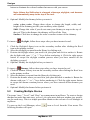
We will start with the floor of the house, called a slab in myHouse. Select Slab from
the Draw menu. Drag the mouse to the right and select Rectangle from the pop-up
menu. Or, click the Slab icon on the top toolbar, then the Rectangle slab icon on the
secondary toolbar that appears on the left.
Position the cursor, which should now be a set of crosshairs, in the upper- left hand
portion of your drawing area and click once. Then drag the crosshairs towards the
opposite corner of your drawing area and click again to lock in that corner. Your
drawing area should now have a rectangle in it. Make sure the rectangular slab is quite
large as we will be adding design elements to it.
If you are unsatisfied with the slab you have created, select Undo from the Edit menu
and start over.
Draw a rectangle slab
myHouse - 34
Quick Start
4.2
Draw exterior walls
Select
icon or Wall from the Draw menu. Drag the mouse to the right and select
Rectangle from the pop-up menu. Or, click the Wall icon, then the fourth icon down
on the secondary toolbar.
Place the cursor over the upper-left hand corner of the rectangular slab you just created
and click once. Drag the cursor to the opposite corner of the rectangle slab and click
again.
4.3
Draw interior walls
Select Wall from the Draw menu. Drag the mouse over and select Single from the
pop-up menu. Or, click the third icon down on the secondary toolbar.
Move the cursor to the inside edge of one of the exterior walls you already created.
Click to anchor the first endpoint of the wall, then move the cursor until you are
satisfied with the wall’s length. Click to anchor this second endpoint.
Note: If your walls are not being drawn at right angles to each other, select
Ortho from the Options menu.
Shift, Ctrl: Holding down Shift or Ctrl during editing allows you to
introduce new elements at an orientation in increments of 45 degrees (0,
45, 90).
Space: When drawing a wall, pressing Space modifies its thickness.
Pressing Space also toggles between superimposed elements to assist in
selecting them.
Continue drawing interior walls until your design looks like the one below.
myHouse - 35
Quick Start
4.4
Draw doors
Select Door from the Draw menu. The Door library will open on the
right-hand side of your drawing area. Click on Door in the Door library. Then, place
the cursor on a wall in your design and click. A rectangle appears, representing a
door. Move the cursor to slide the door along the wall and click again to anchor the
door.
Repeat these steps as desired to place doors throughout your plan. If you want to use
the same door style, it is not necessary to reselect it from the library. If you want to
choose a different door style, select it from the door library and place it following the
steps described above.
Note: To change the swing style of a door, click one of the secondary
toolbar icons on the left while the door is highlighted on your screen.
myHouse - 36
Quick Start
4.5
Draw windows
Windows are placed much the same way as doors in myHouse. Select
icon
or Window from the Draw menu. The Window library will open. Click on the
window you want to place in your plan. Then, place the cursor on one of the exterior
walls in your plan and click. A rectangle appears representing the window. Move the
cursor to slide the window along the wall and click to anchor the window where
desired.
Keep placing windows so that your design resembles the one below.
myHouse - 37
Quick Start
4.6
Insert symbols
Select
Symbol icon and drag the mouse to the right to open the library you want.
For this tutorial, select Kitchen. The Kitchen symbol library will open. To place a
symbol in your plan, click on the desired symbol and drag the highlighted outline of the
symbol to where you want to place it. Click again to anchor the symbol. Once the
symbol has been placed, the highlighted outline will remain. Click to enter the same
symbol again or click the Esc or right mouse button to eliminate this outline.
myHouse - 38
Quick Start
You can also open up the symbol libraries by clicking the Symbol icon on the top
toolbar, then clicking the desired library icon on the secondary toolbar that
appears on the left-hand side of the drawing area.
Note: To rotate a symbol, hit the “plus” or “minus” (+, -) keys on your
keyboard or the rotate left or right icon while the symbol is highlighted in
blue. To rotate a symbol that is already in your design, click the pointer
icon, then click and hold the mouse button down on the symbol you want
to rotate. Hit the ”+” or ”-” keys or the
rotate left or right icon.
Relase the mouse button after the symbol has been rotated.
After placing your kitchen symbols, you are ready to place other symbols. You do not
need to close the Kitchen symbols library to access the other symbol libraries. To open
the other symbol libraries, click the
down arrow next to the
library name. The other library choices will appear. Highlight the SABLON library and
click to open it. Or, click the SABLON library icon on the secondary toolbar.
Select a table and rotate it, then place it in your plan. Next, select an appliance
and place it in your kitchen. You can also add a recycling bin, ceiling fan, or other
symbols from any of the other libraries to complete your design project.
Your resulting plan should be similar to the one shown on the next page, depending on
what symbols you placed and where.
myHouse - 39
Quick Start
4.7
Add a roof
Select Roof from the Draw menu. Drag to the right and select Roof from the pop-up
menu. Or, click the Roof icon on the top toolbar and then the
icon down on the
secondary toolbar. The roof library will open. Select “Roof 1A” from the Roof
library. A rectangle appears, representing the roof. Position the rectangle over the
house and click the roof into place. Then, click the right mouse button to cancel the
highlighted roof outline
Designing individual roofs
. Let’s design a simple roof. Use the Automatic roof
designer
feature for this. After clicking on this icon draw the shape of the roof –
by closing in the polygon the roof designer automatically comes up. If you want to
design a roof having an identical shape with the building itself, it is practical to make
the software automatically generate it. You can initiate this by clicking the
and then left clicking at one of the (outer) walls of the building.
icon
Note: If you do not want to use the automatic generation feature, use the
icon whereby you can define the polygon for yourself
The Roof designer module appears, with the top view representation of the roof.
Roof Designer
4.8
Save your design
To save your myHouse plans, select Save As from the File menu. Give your plan a file
name (for example: Tutorial). Click “Save.” Your project is now saved as “Tutorial.”
To check this, select Open from the File menu. Your plan should be listed. Once your
design is given a file name, you can save it automatically while working on it by
pressing the “F2” key. It is a good idea to save your projects often.
myHouse - 40
Quick Start
4.9
View in 3D
One of the reasons for using myHouse is to view your plan in 3D. To view your plan in
3D from the outside, select External View from the 3D menu. Or, click the
3D-External View icon.
This is a painted rendering of the exterior of your design. Your 3D views will default as
painted views but sometimes you may want different types of renderings.
myHouse will also perform
“Wireframe” and
“Hidden-Line” renderings
simply by clicking the appropriate icon on the toolbar.
The icons of the 3D window may be removed (and put back) by right clicking on the
icon bar and choosing between the icons or by the menu opening up after clicking on
the
icon. The items marked with a small pipe are displayed in the icon row
To rotate your 3D view, click any one of the cameras in the upper-left hand corner of
the screen. The 3D picture can be rotated or moved around by these icons, or by the
mouse, including its scroll-wheel.
After viewing your design, you’ll want to return to the 2D view. To return to the 2D
view, click the
Return to 2D icon.
Now, let’s view the plan in 3D from the inside. Select Internal View from the 3D
menu. Or, click the
3D-Internal View icon. A camera outline appears with your
cursor, with its field of view indicated. Rotate the camera using the “+” and “-” keys or
the rotate left or right icon on your keyboard. Position the camera so that it is inside
the walls of the house in your plan. Imagine you are inside the building with the camera
yourself and are looking for a specific angle from which to show the view. Position the
camera to look at the table, for instance. When you have the desired position, click to
anchor the camera. Double-click on the camera and select the 3D view:
myHouse - 41
Quick Start
An Internal View Parameters window opens. This is where you would change the
camera parameters from the defaults. You can change the height at which the “picture”
is taken, as well as other camera parameters.
After viewing your design, return to 2D
to make any changes.
4.10 Add dimension lines
Most projects you create will need some type of dimensioning. myHouse lets you
dimension automatically or manually. Both options will be outlined here.
Automatic dimensions are used to dimension walls. Select
or Dimension Lines from the Draw menu. Drag your cursor to the right and select
Automatic then
Overall. Or, click the Dimensioning icon on the top toolbar, then
the second icon down on the secondary toolbar that appears on the left of the drawing
screen.
Bring your crosshairs to the drawing area and click once on the wall you want to
dimension. A blue line should appear on this wall. Next, click one endpoint of the
dimension line and drag a line parallel to, and longer than, the wall you just highlightd.
Once you have your line longer than the wall, click again to anchor the second
endpoint. The length of the wall will automatically be given as shown below.
Repeat this process for every exterior walls you want to dimension.
Manual dimensions are used to dimension the distance between any
two points in your plan. The bottom three icons on the secondary toolbar are for
manual dimensioning. Let’s say we want to find out the distance between the table and
the nearest wall. Click the Manual dimension
horizontal line icon and bring your
crosshairs to the drawing area. Click on the wall to anchor the first endpoint of the
dimension line. Drag your crosshairs over and click on the edge of the table. You will
then need to position the dimension line by moving your cursor left or right. When you
have the dimension line in the desired position, click to anchor it.
myHouse - 42
Quick Start
Continue adding dimension lines as needed. You can experiment with the vertical or
angled manual dimension lines by clicking on the appropriate icons on the secondary
toolbar.
4.11 Add text
Like dimensioning, most myHouse projects will need some kind of text to describe the
plan in further detail. To add text, select
Text from the Draw menu. A
Single Line Text dialog box will appear. Type in the desired text and click “OK.” The
dialog box will disappear. Position your cursor where you want the text.
Add additional text as needed to describe the individual rooms or symbols in the house.
Also, add text to include the date and address of the house, or any other pertinent
information so that it appears on any printouts.
Your completed plan should look somewhat similar to the one below.
Press the “Ctrl F2” key to save your project automatically.
Congratulations! You have just completed your first project using myHouse. Now
you’re ready to start your own home design or renovation from scratch. Simply select
New from the File menu and you’re ready to go. You can even start with one of the
house templates included in the program as described below.
myHouse - 43
Quick Start
4.12 QuickHouse
myHouse also contains a QuickHouse feature with over a dozen house and single room
templates. You simply need to insert the correct wall dimensions and myHouse will
draw the house or room shell for you. To access these templates, simply click the Wall
icon on the top toolbar, then click the House Type Library icon on the top of the
secondary toolbar that appears to the left of the drawing area.
The Select House Type dialog box will open. Simply select the type you desire and
enter the new dimensions and click “OK.” Then anchor the house shell onto the
Drawing Area by clicking it into place.
myHouse - 44
Chapter
V
Designs
5 Designs
This chapter outlines the steps for “drawing” building elements in your design. With
myHouse, inserting elements such as doors into a 2D floorplan is simple. All that’s
involved is a couple of clicks on menu items or icons, followed by a click or two in the
drawing area to place and anchor the building element.
Besides the insertion of building elements, another part of creating a myHouse
floorplan is modifying these elements - their placement, shape, rotation, height, color
and so on. You can modify these elements either before you insert them or later, after
they’ve been inserted, as you review your plan.
Remember that myHouse building elements include:
Structural elements such as walls, pillars, slabs, windows, doors, roofs, stairs, and rails.
Appliances, furnishings, and landscaping elements commonly found in and around
buildings and houses.
You can also draw 2D building elements with the Drawing Tools icon. Such custom
symbols act as placeholders in the floorplan, reminding you of a specific type of
element you plan to include. Because these custom elements will not appear in 3D,
their creation is covered in the next chapter. You will, however, be able to use the 3D
Modeler functionality of myHouse to create custom 3D symbols of your own that will
appear in both 2D and 3D. This creation is covered in a separate chapter later in this
manual.
5.1
Creating Building Elements
Each building element has default parameters. You can alter these parameters by
selecting
icon or Default Values from the Options menu, and dragging to the
right to select either Walls, Slabs, Columns, or Stairs, etc.
5.1.1
Using the Keyboard to Enter Elements
When you’re experimenting or just sketching plans quickly, you’ll probably draw
elements using the mouse. There’s nothing as fast and as easy as inserting a set of four
walls with a couple of clicks and a slide of the mouse.
If you’re serious about creating a floorplan absolutely accurately, though, you’ll need
to use a considerably greater level of care as you draw elements. For this accuracy, turn
to the keyboard.
myHouse - 46
Designs
For example, let’s use the keyboard to enter specific coordinates for the endpoints of a
wall. Position the crosshairs where you want the first endpoint to be and click with the
left key of the mouse or hit "Enter" This locks in the first endpoint. Next, hit “x” or “y”
on the keyboard.
Type 13’ in the “dx” box and hit “Enter.” Now, without moving your mouse, hit
“Enter” again to lock in the second endpoint 13’ away from the first endpoint.
You can experiment by entering different values in either the “dx” or “dy” boxes in the
Coordinates lines.
Note: Using negative values in the “dx” or “dy” numbers will draw the wall
to the left or down. Use Tab key to go into the next field.
Or, you can use the arrow keys on your keyboard to create walls. Position the
crosshairs where you want the first endpoint to be. Hold “Shift” down and press your
arrow key in the direction you want to go. You’ll notice the wall is created in 1’
increments. Release the “Shift” button and you’ll notice the wall is created in 1” or
1/16" increments when you press the arrow keys. Hit “Enter” when you have the wall
the length you desire.
Note: For creating walls down to the 1/16”, press the “F3” key after
anchoring the first endpoint. “F3” toggles between 1” and 1/16”
increments.
The keyboard is also used to control symbol rotation. Pressing the “+” or “-” keys
before the symbol has been anchored into place, rotates the symbol by 45 degrees.
Note: To rotate symbols in increments of 5 degrees, press the “Shift F3”
key or the rotation angle icon before rotating. “Shift F3” or click on the
texts acts as a toggle between 45 degrees and 5 degrees.
5.1.2
Slabs
If you are either starting a design or creating a ceiling for a single story building, slabs
are the place to be. Slabs serve as both floors and ceilings. Floors of upper levels are
the ceilings of the lower level. If you did not place a slab between two levels, you
would have a cathedral ceiling for the lower level.
Note: Slabs can also be used as shelves, counters, and beams for
ceilings. Simply modify the length, width, and vertical shift as needed.
In the list of steps below, you can modify the slab parameters before you create it. Or,
you can just draw the slab now and modify it later.
myHouse - 47
Designs
1. Select
icon or Slab from the Draw menu. Drag the mouse to the right and
select Rectangle,
Polygon or
Automatic slab icon.
2. Optional: Modify the slab before you enter it. After clicking the Slab icon,
secondary slab icons will appear on the left of the drawing area. This is the
secondary toolbar. To change the slabs parameters, click the
top icon on the
secondary toolbar. Click this icon to change the thickness, vertical shift, or surface
properties of the slab you’re about to draw. The following dialog box will open.
Slab dialog box
The dialog box shown is for the Rectangle Slab Settings.
Thickness: Change this value to change the thickness of the slab.
Width and Width: These parameters appear only for rectangular slabs. These
values define the initial lengths of the slab’s sides. Change these values if you’re
going to use your keyboard to enter the slab into your floorplan. If you’re going
to use your mouse, leave these values alone.
: Vertical Shift--Arbitrary: Change this parameter if you need to change
the distance a slab will be from the ground. For example, if you have a split level building in your design. If not, Select the
/
Bottom/Top or leave
this value as “0” as the slab will automatically be placed as the floor.
Visualization: This is where you define what surface type you want. Click the
corresponding color tile for “Top” , “Side” or “Bottom side” to add textures to
your slab. These textures will show in 3D.
Click “OK” when you have made all the changes you desire.
3. Now, let’s draw the slab. Click in the drawing window to anchor one corner of the
slab. Drag the cursor, or use the arrow keys, to create the size slab you desire and
click to anchor the opposite corner.
For a Polygon slab, click to enter the first point and move the cursor to the second
corner and click to anchor it. Continue with as many corners as you need to complete
myHouse - 48
Designs
your slab. To close your slab, click on the first cornerpoint again.
To create a split - level building, use two or more slabs in the same level.
Change the Vertical Shift in the Slab dialog box to control the distance you need that
slab shifted. Select the Arbitrary and Enter a positive value to shift the slab up and a
negative value to shift the slab down. Or, you can make the higher slab thicker.
Connect these two slabs with a set of stairs.
5.1.3
Columns
Columns can be used to create many different items in myHouse. Use Columns if you
need beams, pillars, footings, etc. To enter a column into your design, follow the steps
below.
1. Select
icon or Column from the Draw menu. Drag your mouse to the
right and select one of the three style choices, Rectangle, Circle, or Polygon.
Or, click the Column icon.
2. For rectangle and circle columns, a colored outline will appear with your cursor.
Click to anchor the column in your design. Enter as many as you like. Then, click
the right mouse button or press “Esc” to escape the column creation function.
For a
polygonal column, move the cursor to the location of one of the
column’s cornerpoints and click. Continue to mark other cornerpoints by clicking.
Close the column by double-clicking at the last point or clicking at the original
cornerpoint.
3. To change the default settings for any column style, click the
icon at the
top of the secondary toolbar before inserting the column. The Column Settings
dialog box will open. The Rectangle Column Settings dialog box is shown here.
Pillar settings
Z1, Z2: Change this value to change the height of the column.
Visualization/Surface Properties: Click the color tile to choose a surface
texture for your column. Any change made here will apear in 3D renderings.
myHouse - 49
Designs
5.1.4
Walls
Walls are created much the same way, whether they are the external walls of a building
or the walls of a room inside the building.
To create a wall:
1. Select Wall from the Draw menu and drag your mouse to the right to select the
style of wall you want to create. Or, click the
wall icon, then the corresponding
icon from the secondary toolbar that appears on the left.You can draw
a single
wall,
a rectangle of walls,
polygon of walls, or
curved walls.
2. Optional: Modify the wall before you enter it. After selecting the wall style you
want, click the Current Wall Parameters icon on the secondary toolbar to open the
Wall Settings dialog box.
Wall Settings
Thickness: Change this value to change the thickness of the wall.
Height1, Height2: Change this value to change the height of the wall.
Vertical Shift 1, Vertical Shift 2: Change this parameter to change the
distance the bottom of the wall is from the floor. Most of the time you should
leave this value as “0”.
Match: With this option checked, drawing a wall endpoint close to an
existing wall will cause it to snap to the existing wall.
Visualization: Click on the color tile corresponding to what side you want to
add surface color or textures. Choose the texture you want from the box that
opens and click “OK.” These textures will show in 3D.
Click “OK” when you have made all the changes you desire.
3. Now, let’s draw the wall(s). Click to anchor the first endpoint of the wall. To finish
the wall, follow the directions below for each wall type. A corresponding icon
for each type is on the secondary toolbar.
Single Wall: Move the mouse to set the wall’s length and click to anchor the
second endpoint. Pressing “Spacebar” before anchoring the second endpoint
will f l ip t he wall being drawn to t he other s i de of your crosshairs. By
default, single walls can only be drawn at 90 degree angles. To draw walls at any
myHouse - 50
Designs
other angle, select Ortho from the Options menu.
Rectangle: Drag and click to anchor the opposite corner of the set of four
walls.
Polygon: Move the mouse to the second endpoint of the first wall segment
and click to anchor it. That second endpoint now serves as the first end-point of
the second segment of wall. Move the mouse to create the second segment and click
to anchor the second endpoint of the second segment of wall. Continue in this
fashion. When you have all the desired walls, click the right mouse button to
escape. To draw segments at different angles, select Ortho from the Options
menu.
Curved: Move the mouse away from the first anchored point and click. A
“rubber line” is attached to the anchored points. Move the mouse to make the
curve longer and the arc greater or lesser. Click to anchor the curved wall. Here
you can press the rigth button of the mouse and can select the Radius
Determination menu. A dialog box appears and you can define the radius and
central angle of the curved wall.
To create walls using the keyboard, follow the instructions earlier in this chapter.
Note: Besides clicking and moving the mouse to insert a wall, you can
manually enter specific coordinate values for that element. For example,
let’s say you have clicked the mouse to anchor one endpoint of a wall.
Now, hit the “X” or “Y” key on your keyboard. The dialog box appears,
type a value for one or both coordinates and hit “Enter.” The dialog box
disappears and the wall is drawn to the dimensions you chose.
Walls c a n b e modified in many ways. The bottom
Secondary Wall Toolbar a r e the following:
Merge walls
Unmerge walls
Cut from wall
Build from lines or curves
myHouse - 51
four icons o n the
Designs
5.1.5
Doors, Windows
With doors, choose one from the Door library (each door in the library has a type ID
number). To enter a door, follow these steps:
1. Select Door from the Draw menu or click the
Door icon. The Door library will
open.
2. Select the door you want to insert into your design by clicking on it. Change the height
or width of the door and add a threshold if you want at the bottom of the Door library.
Hit “Enter” after you make a change to the door’s parameters. Click on the wall
where you want the door to be. Move the rectangle that appears with your mouse
until you are satisfied with the location of the door ( or press X or Y and define the
location of the door by typing the value) the and click to anchor it. The door swing
will be in blue. Using the
icons on the secondary toolbar, you can change
the swing of the door. Click on any of the icons described below to change the swing
or appearance of the door in your plan while it is blue. Once you have the
desired door appearance, click anywhere else in the drawing area to turn the door
swing black.
5.1.6
Stairs
Many stair styles are possible with myHouse. You can create a straight set of stairs,
which is the default, or stairs that are U or L shaped. With the help of the Stair
Designer, you can even create circular and other custom stair- cases.
Create stairs in the level from which they originate. To create a straight set of stairs,
follow the steps below.
1. Select Stairs from the Draw menu and drag to the right to select Stairs icon. Or,
click the
Stairs icon.
2. Select one of the stair icons:
Stairs icon-straight flights
Stair Designer icon-straight, winding and curved flights
3. If you select the
Stairs icon-straight flights:
Click the Current Stairs Parameters
open the Stair Settings dialog box.
icon on the secondary toolbar.This will
myHouse - 52
Designs
Stairs settings
Change these values as needed. When you have made all the necessary changes,
click “OK.”
Width: Change this value to change the width of the staircase.
Stairs Riser : Change this value to change the height of each
individual stair.
Stairs Tread: Change this value to change the length of each stair.
Stair Number: Enter the number of stairs you need.
Vertical Shift: Change this value to control the stair shift. This value
indicates the distance from the bottom stair to the floor of the current level.
Visualization/Surface Properties: Click this color tile to add a surface texture
to your set of stairs. Choose the texture from the window that opens.
Note: Multiply the number of stairs by the stair riser value to calculate the
height of the staircase. In most cases with a straight staircase, this value
should equal your wall height.
Again, once all your changes have been made, click “OK.”
4. Click the Stairs icon on the secondary toolbar to select the stairs you just created.
Position the staircase in your drawing area, rotate it as needed by pressing the “+”
or “-” keys, then click it into place.
Note: The arrow on a set of stairs points to the top of the stairs.
5. If you select the
Stair Designer icon-straight, winding and curved flights icon:
The program gives you the opportunity to design stairs. Click on the icon to call the
Stair Designer. After starting the program, the Stair Designer appears. However,
the program contains a very efficient automatic Stair Designer method which you
would use in most cases.
In the automatic stair-generating window, you may enter all the stair data such
as: flight width, flight type (straight, drawn or arched), etc. the dimensions for each
step. There is a multi-window dialog box for every flight where you can define
the stair balusters, the individual stair data, the stair landing, the dimensions of
stair rails. You may enter several data in the different windows. To switch to
myHouse - 53
Designs
different windows, click on the small tabs where their names are shown. (See the
Stair Designer manual)
5.1.7
Rails
Rails can be placed on stairs or anywhere else you might find them. To enter rails,
follow the steps below.
1. Select Rail from the Draw menu. Or, click the
Rail icon on the primary toolbar
or on the secondary toolbar of the Stairs.
2. Select a rail from the library that opens. You can modify the rail before you enter it
by changing the height and vertical shift in the library window. Hit “Enter” after
you make a change.
3. Click on the first endpoint for the rail, which is usually at one end of a set of stairs. A
“rubber line” follows the cursor as you move it to the other endpoint. Click
to anchor that second endpoint.
By default, you can create another rail. Click the right mouse button (or press “Esc”) to
escape the rail drawing process. The rail will appear as a heavy, colored line and will
automatically follow up and down the stairs.
5.1.8
Symbols
Symbols in myHouse are grouped into a lot of different libraries. You can also create
your own 3D symbols and custom libraries using the 3D Modeler.
To insert a symbol into your design, follow these steps:
1. Select Symbol from the Draw menu and drag your mouse to the right to select
one of the symbol libraries. Or, click the
Symbol icon on the primary toolbar.
The secondary toolbar will appear to the left of the drawing area. Click any
of these icons to open the corresponding symbol library.
2. The symbol library you chose opens in the Symbol Library dialog box, one
example is shown here. Simply scroll through the library to find the symbol you
want and click on it.
3. Optional: Modify the symbol before you enter it. In the dialog box, you can
change the symbol’s size, color (surface), and shift.
x-Size, y-Size, z-Size: The x size is the symbol’s width. The y size is the
symbol’s length. The z size is the symbol’s height. Change these values as
needed.
Propotional: Swich on/off
Vertical Shift: This is the distance the symbol will be placed off the floor. For
example, to place kitchen cabinets halfway up a wall, you should change
this value.
Also, be sure to change this value if you are placing one symbol on top of
another. For example, to place a lamp on a table, notice the height of the table
when you place it. Then set the vertical shift value for the lamp to be the
myHouse - 54
Designs
height (z-size) of the table.
Surface: Click here to change the color or surface texture of the symbol.
Line type: Click here to change the line style (style, thickness, color,) of the
symbol on the 2D floorplan.
4. Reselect the symbol once all the desired changes have been made. You’ll have a
colored outline of the symbol follow your cursor. Position the outline where you
want the symbol to be in your plan. Rotate it by pressing the “+” or “-” keys on your
keyboard. Click to anchor the symbol.
The colored outline will stay with the cursor after you place the symbol. Click the
right mouse button to get rid of this outline, or click the left mouse button to place this
same symbol again.
5. Optional: Select a different symbol from the same library or change libraries by
clicking the down arrow next to the library name at the top of the Symbol Library
dialog box.
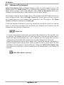
5.1.8.1 Photo Library
Choose the photo library by pressing the last icon of symbol libraries. A photo that you
place in myHouse's 3D rendering will be placed only as a plane that will be rotated
along with the building. Therefore you should place the photo into the proper position
in 2D, using the "+" or "-" keys on your keyboard.
You can also create your own photo symbols and add them to the library using the
Options/Default Value/Photo Symbol command. Use the New Library button to create
your own photo library. Then press the Browse button to select and the Add button to
add the .BMP file to the library. Using the Select 2D button, you can also add a 2D
symbol for your floor plan. Next, add a Description to the file using the Description…
button or (optionally) resize the picture with the Size button. Finally, you can delete
the selected symbol from your library with the Delete button.
Note: In order for the photo symbol background not to be visible in
the 3D painted pictures, it must be black. It the background is black, then
only the desired fore- ground part of the photo symbol will appear in the
3D painted pictures.
myHouse - 55
Designs
5.1.9
Roofs, Chimneys, Skylights, Dormers
Automatic Roof Designer icon
myHouse contains a number of pre-defined roofs for the buildings in your designs. You
insert roofs into your plan much the same way as you insert other symbols. Also,
custom roofs can be built using the Roof Designer.
To insert a Roof, follow these steps:
1. If neccesary, open the top level of your plan. The roof will automatically snap to the
top of the current level.
2. Select Roof from the Draw menu and click on Roof from the menu that opens when
you drag your mouse to the right. Or, click the Roof icon on the primary
toolbar then click the top icon on the secondary toolbar that appears to the
left of the drawing area. This will open the R o of Library dialog box.
3. Select the roof style you want from the library.
4. Optional: Modify the roof before you enter it. In the dialog box, you can change
the roof’s length, width, pitch, and surface properties.
x-size, y-size, z-size: The x size is the roof’s width. The y size is the roof’s
length, and the z size is the roof’s height. Change these values to change the size
of the roof.
Note: Changing the z size of a roof symbol changes the pitch of the roof.
Vert. Shift: Roofs will automatically snap to the top of the level you are on.
Change this value only if you want a non-standard placement of the roof.
Surface: Click here to change the color or surface texture of the roof.
5. Once all the desired changes have been made, position the roof in the design
and click to anchor it. Remember, you can rotate the roof like any other symbol.
The colored outline will remain until you click the right mouse button or press
“Esc.”
Note: Roofs are automatically sized to fit the main building in your plan.
Change the x, y, and z, values as needed before placing any non-standard
roof.
To insert a
Chimney, follow these steps after you have inserted a roof.
1. Click the Chimney Library icon on the secondary toolbar after clicking the Roof
icon.
2. Select the chimney style you want from the library box that opens.
3. Position the chimney in your plan and click to anchor it. Click your right mouse
myHouse - 56
Designs
button to eliminate the colored outline that moves with your cursor.
Note: Unless the Shift value is changed, chimneys, skylights, and dormers
will automatically snap to the top of the roof.
4. Optional: Modify the chimney before you enter it.
x-size, y-size, z-size: Change these values to change the length, width, and
height of the chimney just like you would any other symbol.
Shift: Change this value if you do not want your chimney to snap to the top of
the roof. This is the distance the chimney will be off the floor.
Surface: Click here to change the color or surface texture of the chimney.
To insert a
Skylight, follow these steps after you have inserted a roof.
1. Click the Skylight Library icon on the secondary toolbar after clicking the Roof
icon on the primary toolbar.
2. Select the skylight you want from the library by clicking on it.
3. Position the skylight where you need it in your plan and click to anchor it. Rotate
the skylight with your “+” or “-” keys before anchoring it. Click the right mouse
button to escape the skylight creation process when you have entered all the
skylights you need.
4. Optional: Modify the skylight before you insert it.
To insert a
Dormer, follow these steps after you have inserted a roof.
1. Click the Dormer Library icon on the secondary toolbar after clicking the Roof icon
on the primary toolbar.
2. Select the dormer you want from the library by clicking on it.
3. Position the dormer where you need it in your plan and click to anchor it. Rotate the
dormer with your “+” or “-” keys before anchoring it. Click the right mouse button
to escape the dormer creation process when you have entered all the dormers you
need.
4. Optional: Modify the dormer before you insert it.
5.2
Creating Multiple Stories
The terms “story,” “level,” and “floor” are synonymous in myHouse. To create a design
that has has more than one story, or level, you open more than one window in a project,
one for each story. This is a simple procedure thanks to the exclusive Level Manager in
myHouse.
To open up the Level Manager, select
following window will open.
icon or Level from the View menu. The
myHouse - 57
Designs
Level Manager
A small example floorplan is shown in the window.
Add level: Click on this button to add a new floor, or story, to a plan. Choose
whether you want to copy the current level or leave it empty and where you want
the new level to be. Click “OK” to add the new level.
Delete: Remove level Click on this button to delete the current level.
Level Height: This is the height of the current level, or story. Change this
value to the height of the tallest wall in the story if you have changed any of
the wall heights.
Headroom: The default value here is the default height of a wall.
Slab thickness: Level height= Headroom + Slab thickness
Name: You can name each individual level in myHouse. Changing the name here
will change the name of the level on the level tab at the bottom of the dialog
box.
Note: To switch levels in a multi-level design, click on the desired level tab
at the bottom of the Drawing Area.
myHouse - 58
Designs
5.2.1
Using Layering to Align Levels
As you begin to work with a new story, or level, in a building, one of your first
questions will be, “How do I align a new level with the one above or below?” Such
alignment is easy with the layering capability of myHouse.
Level foils settings
Make the new level the current one by clicking it’s level tab at the bottom of the
drawing area. Next, select Level Foils from the View menu. Select the level you wish
to view by clicking it, then click “Close.” All the walls in that level will appear in color
on the current level. You can now create your walls by tracing them over the colored
ones of the other level to ensure that your levels align themselves properly.
5.3
Modifying Building Elements
Common Windows editing commands are available in myHouse. Two common editing
procedures - select and move - are desrcibed here. In addition, specific information
about each building element is provided in this section.
Select: The first step in modifying elements is to select an element or
elements. Generally, when a building element is selected, it changes color. (A
colored line appears inside walls to show that they are selected.)
Select an object by clicking the Selection Tool
icon, then by clicking on that
element. You can select a group of elements by drawing a box around the group of
elements desired. Or, choose Select All from the Edit menu to select all the elements in
the design.
Note: To select an element that is on top of another element, click the
Selection Tool icon and click on the element. Then, press the Spacebar.
Pressing Spacebar toggles between overlapping elements.
As you perform an operation, a colored outline of the symbol (or a line, in the case of a
wall) indicates the effect of this operation. In other words, if you select a wall and move
one end of it by dragging the cursor, a colored line representing the wall moves with
the cursor. Only when you click to anchor the new position of the wall’s endpoint does
the wall itself move.
myHouse - 59
Designs
Move: Once you have selected an element, the easiest way to move it to a
new location is by dragging that element. Click and hold the mouse button down
while dragging the element. Once you have the element in the new desired
location, release the mouse button. If, while dragging, you cannot drag at an
angle, select Ortho from the Options menu.
You can also move objects using the button. When the objects are selected press the
button and use the cursor arrow keys to move them in 1” or 1cm steps (Shift f+ 1/16",
1mm). Hold down the Shift key to move the objects in 1’ or 1m steps.
5.3.1
Slabs
You can modify a slab in the following ways:
1. Move it: Select the slab, place the cursor anywhere on the slab, and drag it to the
new location.
2. Change its parameters: Double-click on the selected slab to open the Slab
5.3.2
Walls
You can modify a wall or set of walls in the following ways:
1. Move it: Select the wall. If you click and drag in the middle of a single wall, the entire
wall moves. If you click and drag on one end of a free-standing wall, only that end
moves and the other end stays anchored. The cursor will become a circle when you
can modify this way.
2. Change the shape: Select a wall, click on one of its endpoints or on a
cornerpoint where walls join, and drag the endpoint or cornerpoint to a new location.
You can turn a rectangular set of walls into a polygon in this fashion.
3. Change its parameters: Double-click on a selected wall to open the Wall Settings
dialog box. Make the desired changes and click “OK.”
4.
Adjust a wall junction: Click on the intersection of t he t wo walls t h at
a re n ot matched. T he walls a r e automatically redrawn as a single building
element.
Unmerge walls.
5.
Cut a wall: Select Edit Wall from the Edit menu and click Cut Wall in the
pop-up menu. Or, click the Wall icon, then the icon on the secondary toolbar that
controls this feature.
Click at the point in the wall where you want one edge of the cut. Move the cursor
to the other end of the cut and click. The wall will be redrawn with the cut shown.
6.
Turn a line into a wall: Click on the Wall icon to open the secondary wall
toolbar. Select the line and then click on the Build Walls From Lines or Curves
icon on the secondary toolbar.
myHouse - 60
Designs
5.3.3
Doors, Windows
You can modify a door in the following ways:
1. Move it: Select a door, click on it and drag it to a new location on the
same wall.
2. Change its parameters or type: Double-click on a selected door to open
the Door library. Choose a new door style or change its height and width.
Press “Enter” after you make your changes.
3. Change the swing, etc. : Select a door. Then, while it is selected, click
one of the icons on the secondary toolbar to change its swing, etc.
4. Add or delete a threshold, sill: Double-click on a selected door to open the
Door library. Click on the Threshold or Sill checkbox to add or delete a
threshold or sill in that door or windows.
5.3.4
Stairs
You can modify a set of stairs in the following ways. Be sure to double-check any
changes you make. You could make changes that result in the stairs either exceeding or
failing to reach the next level. Also, note that when you select a set of stairs, it is
marked by handles as well as a colored outline.
This section also contains instructions on creating a U or L shaped staircase.
1. Move it: Select the set of stairs, click on it, and drag the stairs to the new location.
2. Change its parameters: You can change the size of a staircase by dragging the
handles of a selected staircase. Or, double-click on the selected set of stairs. Change
the parameters as needed in the Stairs Setting dialog box that opens.
3. Add rails: For instructions on creating rails, refer to the section on Rails earlier in
this chapter.
4. Connect flights of stairs with a landing: To insert a landing in a set of stairs, you
need to think of the sets of stairs on either side of the landing as separate
segments.
Create a new set of stairs as described earlier in this chapter. Click on the Landing icon
on the secondary toolbar. A colored outline of the landing will appear. Position this
landing at the top of the stairs. Click to anchor it.
Insert another segment of stairs. The Vertical Shift value for this set should equal the
height of the first set of stairs plus the landing. The bottom of this set should be
attached to the landing.
You can create different stair shapes by putting together different shaped landings and
stair segments of various lengths. The following picture is a close up of an “L” shaped
staircase.
myHouse - 61
Designs
5.3.5
Rails
You can modify a rail in the following ways:
1. Move it: Select the rail, click on it, and drag it to a new location.
2. Change its length with the mouse: Click on one end of the rail and drag the cursor to
lengthen or shorten it.
3. Change its parameters: Double-click on a selected rail to open the Rail library.
Press “Enter” after making the necessary changes.
5.3.6
Symbols
You can modify a symbol in the following ways:
1. Move it: Select the symbol, click on it, and drag it to a new location.
2. Change its parameters: Double-click a selected symbol to open the Symbol library.
Change its parameters as needed and press “Enter” after you’ve made all the
necessary changes.
3. Turn it into a different symbol: Double-click a selected symbol to open the
symbol library. Select a new symbol from the library.
5.3.7
Roofs
You can modify a roof in the following ways:
1. Move it: Select the roof, click on it, and drag it to a new location.
2. Change its parameters: Double-click a selected roof to open the Roof library.
Press “Enter” after making the necessary changes.
3. Add elements: To add skylights, dormers, or chimneys, see the Roof section earlier
in this chapter.
5.3.8
Columns
You can modify a column in the following ways:
1. Move it: Select the column, click on it, and drag it to a new location.
2. Change its parameters: Double-click a selected column to open the Column Settings
dialog box. Press “Enter” after making the necessary changes.
3. Change shapes: The best way to change the shape of a column is to delete the
current one and create a new column of the desired shape.
Note: To rotate a symbol, roof, column, or set of stairs after they have
been anchored; Select the desired element and press the “+” or “-” keys
while holding the mouse button down.
myHouse - 62
Chapter
VI
Enhancements
6 Enhancements
This chapter describes various ways of enhancing your myHouse design. For example,
you can draw “primatives” to enhance your plan, or insert dimension lines to note
distances. Text can also be added to put notes right on the plan. Lastly, this chapter will
describe the automatic Bill of Materials.
6.1
Drawing Primatives
Primatives are used for many reasons in myHouse. You can draw a circle to represent a
symbol, draw a line to point out important aspects, measuring area, or add text to make
the plan easier to understand.
Note: Primatives will not be viewable in 3D. To draw custom symbols that
will be viewed in 3D, use the 3D Modeler as de scribed later in this manual.
To draw a primative, click the
Drawing Tools icon. The secondary toolbar will
open which allows you to choose what style primative you want to draw. The steps
involved in drawing each primative are outlined below.
Draw a line: In the drawing window, click to anchor one endpoint and
move the cursor to where you want the line to end. Click to anchor the second
endpoint.
Draw a polyline: Click to anchor the endpoint of the first segment, move the
cursor and click again to anchor the second endpoint. Move the cursor in a new
direction and click to anchor the next endpoint. Continue as long as you need to.
Click the right mouse button to escape this drawing process.
Draw a rectangle: Click to anchor one cornerpoint. Move the cursor
to the opposite cornerpoint and click to anchor that corner
Draw a circle based on center and radius: Click to anchor the center of the
circle. Move the cursor away from the center point and click to anchor the
circle.
Draw a circle based on 3 points: Click to select the first point, and again to
select the second. Move the cursor and define the size of your circle by clicking
in the third point.
Draw an arc based on center, radius, and angle: Click to anchor the center
of the circle. Now, click on a point along the circumference. This point will
serve as the endpoint for the arc. Then, move the cursor up or down to draw the
arc. Click when you have the length arc you desire.
Draw an arc based on 3 points: The arc is defined by three anchored points.
Click to anchor all three points.
myHouse - 64
Enhancements
Fill area
Text: Click the Insert Text icon. A Single Line Text dialog box appears.
Text settings
In the text field, enter the word(s) you want to add to your floorplan. Change
the default height of the text if you desire. Click “OK” when finished. Select the
text directin:
Click the point at which you want the text phrase to begin. Draw a line by
moving the cursor to the right away from the anchored point. Click again to
insert the text.
If your text is in the wrong place, select it and drag it to the new location. A
colored box will surround the text when it is selected.
Bitmap symbols: For additional flexibility, myHouse lets you insert
BMP, JPG, EMF, WMF files into your design. Sim- ply select Bitmap symbols
from the Draw menu and browse the files. Once you have located the file you
want, set the scale, density, width, and height and then place it in your design.
6.2
Drawing Dimension Lines
Dimension lines are used to show distances between identified points in your plan.
myHouse gives you many options for dimension lines. You can place them inside or
outside a floorplan, you can choose from a variety of styles, and you can have them
drawn manually or automatically.
To draw a dimension line, select Dimension Line from the Draw menu. Then, select
Automatic or Manual. If you select Automatic, the dimension line will change
automatically if you later change the length of a wall.
myHouse - 65
Enhancements
There are five options for Automatic and three options for Manual. They are
accessed by clicking the pop-up menu that appears. They are also accessable by
clicking the corresponding icon on the secondary toolbar after clicking the
Dimensioning icon.
Overall automatic - Drawing an exterior overall dimesion line:Use this
option to measure walls. Select the wall you want to dimension. Click to anchor
one endpoint of the dimension line and move the cursor to draw a line parallel
to, and at least as long as, the wall you selected. Click to anchor the second
endpoint. The dimension line will appear.
Detailed automatic - Drawing an exterior detailed dimesion
line: This option provides a detailed measurement of a wall, broken among
endpoints, windows, and doors. Select the wall and follow the directions for
Overall automatic.
Internal automatic - Drawing an interior dimesion line: Use this option
to make internal measurements such as the width of a wall or the internal
dimension of a room. Click the endpoints of the line across the space you want
to measure. The dimension line will appear.
Horizontal manual: Use this option to draw a horizontal dimension line.
Click one endpoint of the line, move the cursor to draw a line horizontally and
click to anchor the second endpoint. Move the cursor up or down and click to
position the dimen- sion line. The dimension line will appear.
Vertical manual: Use this option to draw a vertical dimension line. Click to
anchor one endpoint of the line, move the cursor to draw a line vertically and
click to anchor the second endpoint. Move the cursor left or right and click to
position the
dimension line. The dimension line will appear.
Angled manual: Use this option to draw an angled dimension line. Click to
anchor one endpoint of the line, move the cursor to draw a line and click to
anchor the second endpoint. Move the cursor left or right and click to position
the dimension line. The dimension line will appear.
Measureing areas
Note: Use the Manual dimension lines to dimension anything other than
the length of a wall. For wall lengths, use the Automatic dimension
lines.
myHouse - 66
Enhancements
6.3
Measuring Areas
To measure an area in myHouse, select Measure Area from the Draw menu or select
their icons.
Click to a colsed by walls area to be measured.
Click to anchor the corners of the area to be measured.
Now, as you move the crosshairs, a “rubber line” is attached. Click to anchor the next
corner of the area. Continue until you are back to the original corner. If you can only
draw the lines at 90 degree angles, select Ortho from the Options menu.
Once you close the area, the Single Line Text dialog box will appear with the size of
the area you have defined already entered. Click “OK.”
Settings of measured area
Insert the area size label the same way you would ordinary text. Click where you want
the text to be.
6.4
Modifying Dimension Lines
You can modify dimension lines in the following ways:
1. Move it: For automatic lines only, click and drag a selected dimension line to to a new
location. You will not change the measurement itself.
2. Change its length: For automatic lines only, increase or decrease the length of a
dimensioned wall. The dimension line adjusts to these changes.
3. Changes its parameters: You can also make other changes to all the new
dimension lines you will draw. Select Dimension Settings from the Options menu.
The Dimension Line dialog box will appear.Each option is described below.
Style: Select one choice from this list to represent the tick marks on the
dimension lines.
Text Position: Select one option from each group to represent where text will
appear in relation to the line.
Automatic Dimensioning: Select the point on the doors and windows that is to
myHouse - 67
Enhancements
be used to measure the distances between wall endpoints, doors, and windows.
This option applies to Detailed lines only.
Distance: Specifies the distance between the text and the dimension line.
Text Height: Specifies the height of the text.
Click “OK” after you have made all the desired changes. These changes will not be saved
when you exit myHouse.
6.5
Using Grids
myHouse uses a snap-to grid system in the drawing window to increase the speed with
which designs are drawn and improve the accuracy with which design elements are
placed. Elements can be snapped to a close gridpoint. To disable snap, select Snap
from the Options menu and click “Enable snap” in the Snap Settings dialog box so the
check mark dissappears. You can also change the distance with which design elements
will be snapped to a close gridpoint by increasing the number of Pixels. Select
Change Grid from the Options menu to open the Grid dialog box.
Grid Setup
Here is where you change the size of the grid or determine whether you want the grid to
be visible like a point or line in the level you’re working on, or on all levels. You can
also toggle between a visible and nonvisible grid by selecting Grid from the View
menu.
myHouse - 68
Enhancements
6.6
Changing Units
myHouse also lets you create your design using Metric measurements. To change to the
Metric system, select Change Unit from the Options menu. These changes will not be
saved when you exit myHouse.
Metric Settings
6.7
Texture setting
You can insert new textures into the library using the Options/Textures Settings
command. Press Texture type to select the type, then the Browse and Add buttons to
locate and add .a BMP file to the library. You can delete the selected symbol from your
library with the Delete button.
Texture settings
6.8
Bill of Materials
myHouse automatically generates a catolog of everything you place in your design. To
open up the Bill of Materials for the plan you are currently working on, select Bill of
Materials from the File menu.
Below is an example of an automatic bill of materials.
The Bill of Materials is in spreadsheet format compiled from the design. To change text
in a cell, click on the cell, enter the information you need and press “Enter.” Under File
and Options, you’ll notice that this inventory can be saved, printed, and modified much
the same way as other spreadsheet applications.
Select Export from the File menu in the Bill of Materials to export your inventory to a
file format for easy manipulation in your favorite spreadsheet or database
application.
myHouse - 69
Enhancements
myHouse - 70
Chapter
VII
Views
7 Views
Your myHouse design is created in the 2-dimensional view. There are several
commands in this 2D view that can help you draw and modify your plan. For example,
you can zoom in on part of the plan, or use the layering command.
Part of the usefullness of myHouse is in its 3D viewing capability. Your 2D plans are
transformed to 3D renderings with a couple of clicks of the mouse. Use these 3D views
to help you visualize and critique your plan. For example, you can create a 3D movie,
to simulate taking a video recording around the inside our outside of your design. You
will even be able to save and replay this movie over and over.
7.1
Viewing in 2D
To change the 2D view of your plan, select a command from the View menu. Each
command is described below:
7.1.1
Zoom
Zoom In: Increases the appearance of the design.
Zoom Out: Decreases the appearance of the design.
Zoom Window: Lets you select the portion of the design for which you want to
increase the appearance. Drag a box around the area of the design you want
to zoom into. When you click to enter the second cornerpoint, you will
automatically be zoomed in on the boxed in area. This option is also accessible
by clicking the Zoom Window icon.
Zoom to Extents: Increases or decreases the appearance of the design, to
the extents of your floorplan, by placing the whole floorplan in the drawing area.
Last Zoom: Redisplays the last view of your design.
Default Zoom: Redisplays the original view of the design.
Set Zoom Window: Lets you specify a zoom view to redisplay. The Zoom W
indow Setup dialog box will appear. Change the specified values to change the
size of the viewable screen. Click “OK” after making the changes.
Air View: Displays the entire plan in the Air View dialog box. The colored outline
will designate the drawing area. Drag the colored outline to change the display
in the drawing area. This option is also accessible by clicking the Air View icon.
Redraw: Redisplays your current view. Select this option periodically to
“refresh” your drawing area, especially after making some modifications to your
design. This option is also accessible by clicking the Redraw icon or by
pressing F6.
myHouse - 72
Views
7.1.2
Foils - Layering
The Folis dialog allows you to choose those elements in your design which you want to
view. Think of each set of elements as residing on a layer. For example, the layers
might be doors, symbols, roofs, slabs, etc. You use the Layering command to view or
hide the elements you choose.
1. Select Foils from the View menu to open the Foils dialog box. An example is on
the next page.
2. Click the appropriate tab: “Elements” lists the design elements, and “Levels”
lists the available floors, or levels.
3. Choose one of the following:
Click individual items in the list, until it is selected or deselected. As you change the
selections on the list, your plan is automatically redrawn.
Click “Show all” to show all the elements or levels in the list. Click “Hide all” to hide
all the elements or levels in the list.
7.2
Viewing in 3D
3D visualization of the project: from the outside and inside. The project can be
visualized in 3 dimensions at any point. The most basic 3D view is the 3D image of the
entire building from the outside. This is created by simply clicking on the
icon.
The inside view is created by first clicking on the
icon, and then putting down the
camera, doubleclick on the camera and select the 3D view.
myHouse - 73
Views
3D Parameters
3D Camera Setup
The 3D window has a different set of (upper row) icons, the wireframe or painted
image of the project can be seen below. You may change between the wireframe and
colored representations in the 3D/3D parameters menu of the 2D editing window or by
the
icons of the 3D window. The icons of the 3D window may be removed
(and put back) by right clicking on the icon bar and choosing between the icons or by
the menu opening up after clicking on the
pipe are displayed in the icon row
icon. The items marked with a small
The
icons (Alt+1 or Alt+2) enable you to choose between the external:
Examine Alt+1 and the camera Handycam Alt+2 views, while also determining which
set of icons are displayed by switching on the Navigation menu:
the rotating-moving arrow icons
or the camera
adjustment icons
.
The 3D picture can be rotated or moved around by these icons, or by the mouse,
including its scroll-wheel. The adjustment of 3D parameters can be done (partly) in
the 3D/3D parameters menu of the 2D editing window.Other parameters can be
adjusted by clicking on the
icon of the 3D window. For example, you may set
myHouse - 74
Views
the optical parameters of painted images, the line colors for wireframe pictures here.
The dialog has multiple sub-windows. Changing between
hidden line views is possible in Rendering mode by the
the colored and
icons.
3D Options
By
the icons you can change between the perspective and frontal views, these
icons are switched on by clicking on Projection modes in the right click menu. You
may resume to 2D editing by clicking on the
icon.
myHouse - 75
Views
7.2.1
Saving the 3D View
You can save wireframe and hidden line renderings in myHouse as .DXF, .BMP or
.JPEG files. You can save painted views as .BMP or .JPEG files. When you click the
Save icon, the Save dialog box appears, and you must specify a filename.
.WRL, .WRZ you can create virtual reality panoramic images that can be explored
interactively both on your PC and on the Internet. You can navigate within the 360°
scene, jump to another scene, zoom in and out in real time.
7.2.2
Printing the 3D View
You can print from any perspective or angle in the 3D views in myHouse. Once you
have the desired view, follow these steps to print:
1. Click the Print icon
Print image
2. Select the options you want in the Print dialog box that appears.
3. Click “OK.”
myHouse - 76
Views
7.2.3
DreamScape
MyHouse contains a feature where you can place the design of your dreams in the
setting of your dreams. This is the DreamScape feature where you can select from over
75 different full color images to view in the background of your 3D view. These images
are accessed from the myHouse CD by following these directions.
1. Click the Add DreamScape icon
2. In the dialog box that opens, select the file.
3. Double click on the desired DreamScape bitmap. The selected image will appear
behind your 3D rendering.
4. To clear the DreamScape, click the Clear DreamScape icon next to the Add
DreamScape icon.
You can move your plan in this dreamscape. Press the left button of the mouse and
moving the plan with the little hand pressing the mouse button or click on one of the
icon of the rotation arrows or cameras.
7.2.4
Ray Tracing
Ray tracing is a technique for image creation that is capable of producing high- quality,
photo-realistic images. It does, however, require significantly longer calculations than
the usual polygon rendering techniques. Special 3D hardware avail- able for personal
computers implements some simple rendering methods, but, unfortunately, none of
them help with ray tracing. The speed with which ray tracing is carried out ultimately
depends on the power of your processor (CPU). Although ray tracing doesn't require
much memory, setting up some virtual memory is a good idea, especially if you work
with big plans.
You may transfer the 3D image to the ray tracing module
. First, it is expedient to
check the appropriateness of lighting/shadow adjustments on a small preview picture. If
you do not find them satisfying, go back to the painted 3D image and readjust the
lighting settings (direction). If the preview seems to be OK, you should create a picture
of a resolution of at least 1000×700, with smoothing and reflections. The raytraced
image is created in 2 steps (the second being the smoothing of the image). Besides the
default BMP format you may also save the image as a compressed JPG file.
myHouse - 77
Views
7.2.4.1 Panoramic Images
In the ray tracing module of myHouse you can also create panoramic (360 degrees)
images and save them in QuickTime MOV file format. The advantage of panoramic
images is that once created, you can interact with it in a way similar to actually being
present using the QuickTime virtual reality viewer provided with myHouse. You can
look in any horizontal direction, look up or down (within a range determined by image
settings), and zoom in or out. Panoramic images are most useful with interior scenes
because one image holds all that you could see in any direction from the defined
viewing point. The disadvantage of panoramic images is that they need greater
(approximately twice as big) resolution than standard images to look good.
Go to the Options menu and check the “Create panoramic image” box. The resolu- tion
depends on the width of the image, while the vertical range that will be included
depends upon the height. We recommend setting the height to 50% to 80% of the
width.
To change panoramic image options, press the Settings button and use the Options
menu. Note that default vertical zoom angle and image compression quality can be set
after tracing and before saving.
After setting the options, press RayTrace. If you have checked the The image that
appears in the main window looks a bit unusual because it is only a technical
representation of the panoramic image. The final result is shown in a separate window.
Next, you may save the image into MOV file. Later, you can view the image with the
Show option in the File menu.
myHouse - 78
Views
7.2.4.2 3D MovieMaker
The 3D MovieMaker in myHouse lets you create a movie from a sequence of camera
shots. You can save this movie and replay it over and over as a way to walk through
your dream home before construction is complete.
Creating a movie is a simple, three step process, as explained below. First, you place
the cameras in 2D to take the picture frames, then create the movie (you’ll have many
options here depending on what type of movie you desire) and, finally, play the movie.
Placing the Cameras
1. Select Place Camera from the 3D menu. A colored outline of a camera will appear
indicating the field of view.
2. Place the camera in position to capture the first frame of the movie. Rotate the camera
using your “+” or “-” keys until it faces the direction that you want. Remember,
pressing “F3” will rotate the camera in increments of 5 degrees.
3. Click to anchor the camera view.
4. You will still have the colored outline of the camera attached to your cursor. Move and
rotate the camera into position to capture the next frame, and click to anchor it.
5. Choose one of the following approches:
a) Define the remaining shots manually by moving the camera, placing the shot, and
clicking the mouse until you have captured all the frames you want. Click the right
mouse button when you are done to escape the Place Camera function.
Note: The more shots you take and the closer together the shots are, the
more fluid your movie will seem. However, increasing the fluidity will
increase the length of time it takes to create the movie.
Choosing this approach, your design will look something like this:
b) Let myHouse enter a series of camera shots by selecting the second camera
placed and then double-clicking on it to open the Camera Setup dialog box.
Change the options in the dialog box and click “OK” when you are finished.
Camera Direction: Indicates the direction the camera is pointing.
Vetrical Angle: The camera angle in the vertical plane. To look downward, enter
a negative number. To look upward, enter a positive number.
Aperture Angle: Indicates how wide the view will be. The higher the
number, the wider the view.
Height: The height of the camera above the floor.
Steps from the Previous Camera: The number of frames automatically added
between the current frame and the previous one. The larger the n u m b er , the
more frames there will be.
Camera Index: The order in which the camera shots will be used in the
movie.
myHouse - 79
Views
Note: You can alter individual camera shots in option “a” by
double-clicking a selected camera to open the Camera Setup dialog box.
If you want to create QuickTime (.MOV) movie
You have to sign the Camera Gate too. Select the Place QT gate from 3D menu. Click two
QT cameras and then on a window or door to select the place of the “gate”. The gate is
the place where you can jump from one room into another. Instead of select- ing a door or
window as a gate you can also draw your own gate by drawing a line or a polygon
simply by clicking its edges and then doubleclicking at the last point.
If you select the gate and then right click or doubleclick on it you can change
the gate’s properties (Height, Vertical shift)
If you draw just a line, the Height would mean the height of a rectangular gate with
the width determined by the length of the line.
If you draw a polygon the gate will be placed horizontaly at the height
determined by the Vertical shift parameter.
Playing the Movie
1. Select Play Movie from the 3D menu. The Media Player will appear. Just below the
Media Player is the screen that will show the movie.
2. Click “Play” to run the movie.
myHouse - 80
Chapter
VIII
3D Modeler
8 3D Modeler
MyHouse includes a large number of predrawn symbols. For most designs and
floorplans, these should be sufficient. For plans that require that special table, bed,
fireplace, or any other symbol, you can create it from scratch using the 3D Modeler.
You’ll also be able to modify any of the symbols in the myHouse libraries.
8.1
The Views
3D MODELER
To properly assemble a symbol, you must look at it from three 2D vantage points as well
as in a 3D rendering. Below is the Modeler drawing screen with a symbol already
created.
The views are:
Y-Z View: The head-on view of the symbol. X-Z View: The side view of the symbol.
X-Y View: The aerial view looking down on the top of the symbol.
3D View: The 3D perspective drawing of the symbol.
In all the views, you see a line drawing without regard to the transparancy of the
various lines and solids in the drawing. Also, individually, none of the 2D views offers
any perspective with relation to the third dimension.
myHouse - 82
3D Modeler
8.2
The Toolbar
Like the main program, Modeler contains a toolbar above the drawing screen.
Each function is explained below. To see the name of any of the icons on the
toolbar, position the cursor over that icon.
Select: Provides an arrow with which to select icons or parts of the drawing
for modifying.
Cut: Cuts the selected object(s) to a special myHouse clipboard.
Copy: Copies the selected object(s) to a special myHouse clipboard.
Paste: Copies the contents of the clipboard to the Modeler drawing area.
The set of simple blue icons are used to create 2D elements that can be decorative,
but have only length and width. They are:
Line Polyline Polygon Triangle Rectangle
Circle
The 3D symbols are green symbols that have length, width, and height. Thes
e can be controlled to be a complete solid or open at the top and/or bottom. The
3D symbols are:
Brick PyramidCone Cylinder Sphere
Hemisphere Gear-wheel
In addition to the icons for drawing elements, the toolbar contains some
advanced buttons used to transform 2D objects into 3D solids. An explanation
of these four occurs later in this chapter. They are:
Solid of Revolution Axis
Prism object and Vector
Spiral Axis
Light source
The next two icons are functions that should be familiar to you from the
myHouse program. They are:
Redraw
Zoom Window
The remaining icon is used to generate a full-screen 3D view of the symbol you are
creating.
Total 3D
myHouse - 83
3D Modeler
8.3
The Menu
There is also a menu above the icons in Modeler. Below is an explanation of the
menu choices that are new. The rest should be familiar to you from the myHouse
program or are explained previously in this chapter.
From the File Menu:
Open from Library: Use this function to open an existing symbol from a myHouse
library into Modeler for custom modification.
Insert to Library: Use this function to insert the symbol created in Modeler into
myHouse. You will be prompted to choose which library you want to insert the symbol.
For best results, create a new library for all your custom symbols by enter- ing a new
file name when prompted. Then, give a description of the symbol and click “OK.”
The symbol will then be added to the library you created.
Delete from Library: Use this function to delete a symbol from one of the myHouse
libraries.
From the Options Menu:
Default Values: Each drawing element (brick, cone, line, etc.) is given a default
size and color. Use this function to change the default size or color of any of the
building elements for accuracy when creating your new symbol.
Note: Select a surface texture for your new symbol from the symbol library
in myHouse.
8.4
Helpful Hints
Don’t worry about where you start building your object. By default, the first object you
insert is in the approximate center of the drawing field, allowing you plenty of room to
build in any direction.
Rotate an element in the desired view with the “+” and “-” keys on your keyboard. The
element will rotate in increments of 5 degrees.
When you are done with your symbol and it has been inserted into a library, you can
modify its entire dimensions before placing it into your design, just like any other
predrawn myHouse symbol.
Whenever possible, modify an existing symbol. That way, some of the work will
already be done for you.
Resize an element by moving the cursor to the red or green corners until the cursor
becomes a two-headed arrow. Hold the left mouse button down and drag the cursor to
resize the element.
If elements overlap, you can select an element by clicking on it and pressing “Ctrl” and
“N” at the same time as necessary to select the appropriate element.
If you have multiple occurrences of the same object (such as table legs), create the first
one and use the Modeler copy and paste commands to replicate it. With this approach,
the table legs will be exactly the same size.
As you move the cursor between the three 2D views, you will see where the element is
myHouse - 84
3D Modeler
placed in the other views, including the 3D view. To make it easier to visualize the
placement, one corner of the object is green and the opposite corner is red. The green
corner corresponds to the same point in all three of the 2D views.
Here are some hints to help in assembling your own symbol.
When an element is selected, you can move it with the arrow keys on the keyboard as
well as the mouse. Use the arrow keys to move the element 1” at a time. Hold “Shift”
down to move the element in 1’ increments.
8.5
Creating a Symbol
This section is a tutorial which will take you step by step through the creation of a desk.
When you are done, the desk will look like this:
1. Start by creating the desktop. Select Default Values from the Options menu and drag
to the right to select Brick. The Brick Setup dialog box appears. Enter these
values and click “OK.”
X Size:
Y Size:
Z Size:
6’-0”
3’-0”
1”
You can also select a color for your desktop by clicking the color tile next to the word
“Surface.”
myHouse - 85
3D Modeler
2. Select the Brick icon and place the large rectangle in the center of the X-Y view so
that it looks like the picture below. To do this, you may need to rotate the rectangle
in the Y-Z view.
3. Next, create the legs of the desk. Select Default Values from the Options menu
and drag to the right to select Cylinder. Make the following changes to Cylinder
Setup dialog box.
Radius:
Height:
1”
30”
Leave the other values as they are and click “OK.”
4.
5.
Select the Cylinder icon and place the cylinder in the X-Z view below the
desktop. You will need to rotate the cylinder by pressing the “+” or “-” keys
on your keyboard so that it looks like the picture on the next page.
Once one leg has been placed, use the Copy and Paste command to create
the three other table legs and position them as they are shown below.
Or, repeat step 4.
myHouse - 86
3D Modeler
Note: For greater accurracy in placement of the table legs, you can zoom
in on the area.
6.Next, we will create some drawers for the desk. Select Default Values from the
Options menu and drag to the right to select Brick. The Brick Setup dialog box
will appear. Enter these values and click “OK.”
X Size:
Y Size:
Z Size:
1’-6”
2’-8”
2’-0”
7. Select the Brick icon and place the rectangle under the desktop in the X-Z view and
position it so the edges of the rectangle meet the edges of the desktop in the X-Y vie
w. The resulting desk should look like the picture on the next page.
myHouse - 87
3D Modeler
8. Save your new symbol. Select Save As from the File menu. Give the symbol a
filename and click “OK.”
9. Insert your desk to a new library for placement into your myHouse plan. Select
Insert to Library from the File menu. Modeler will ask if you want to modify the 2D
and 3D views. Click “NO” for now. You can experiment with this later.
The Insert to Library dialog box will appear prompting you for a file name. For best
results, enter a file name such as “Personal” or “New” or “Custom” or anything
other than one of the names of the current libraries. Click “Open” after entering the
file name.
The Symbol Settings dialog box will appear. Enter a symbol description and click
“OK.” The symbol is now in your new library in the myHouse program.
10. Now we will place your new symbol in a design. Open myHouse and open the plan
you need. Click the Symbols icon and then open any one of the symbol libraries by
clicking an icon on the secondary toolbar. That library will open. To open the
library you just created, click the down arrow next to the library name to bring up
the list of libraries and click the name of the library you just created to open that librar
y. Your custom symbol should be in that library ready for you to modify, rotate, and
place like any other myHouse symbol.
myHouse - 88
3D Modeler
8.6
Advanced Techniques
Solid of Revolution Axis and Prism Vector provide the tools needed to give a 2D
element depth. Use Prism Vector to give elements basic thickness. This could be very
handy when creating a deck with irregular sides. Solid of Revolution Axis gives
elements cylindrical thickness. Both features work in similar fashion.
For example, using the deck example, draw a 2D polygon in the X-Y view and select it
with a left mouse click. Select the Prism Vector icon. In the other two views, you will
see a small green box and a dashed line connected to the 2D polygon. The Prism
Vector icon has also changed to a Prism icon.
Control the amount of thickness to give the element by moving the green box with the
mouse or arrow keys and then click the Prism icon. Modeler will transform the 2D
element into one with three dimensions.
Prism icon
To create exotic figures with curves, use Solid of Revolution Axis. For example, start
by placing a 2D triangle into the X-Z view and select it with the left mouse button.
Select the Solid of Revolution Axis icon. A dashed line with green and red boxes
will appear and the Solid of Revolution Axis icon has changed to a Vase icon.
Anchor this dashed line with a single mouse click. Control the amount of thickness to
give the element with a single mouse click on either the red or green end of the line
and adjust with the mouse or keyboard arrows. Select the Solid of Revolution Axis
icon which now looks like a vase to transform the 2D element into a curve-based 3D
element.
Solid of Revolution Axis icons
myHouse - 89
Chapter
IX
Hints & FAQ’s
9 Hints & FAQ’s
9.1
Frequently Asked Questions
Walls:
Q: How do I add surface textures to a wall?
A: Double click on a selected wall. The Wall Settings window will appear. Click on the
color slide for the side you want to add the texture. Choose the texture you want and click
“OK” twice.
Q: As I’m drawing my wall, I notice the wall is on the wrong side of my crosshairs. How
do I flip it to the other side?
A: Pressing the Spacebar will flip the wall to the other side of your crosshairs.
Q: How do I draw walls at angles other than 90 degrees?
A: You can Disable or Enable the program's Ortho option by selecting Ortho from
Options or pressing Ctrl O. Ortho enforces the drawing of orthogonal walls, walls at 90
degrees to each other.
Q: I can’t seem to get my “Cut Wall” function to work. Why?
A: To cut a wall you need to position your crosshairs in between the two lines that make
up the wall and be at least 6” (or 10 cm) from a wall joint.
Q: Do I have to use the mouse to create walls?
A: No. Use the arrow keys on your keyboard to move the crosshairs 1” at a time and the
“Enter” button to anchor endpoints. Hold “Shift” down to move in 1’ incre- ments.
Q: How do I extend/shorten a wall without having to redraw it?
A: Click the Edit arrow, then position the cursor so it is on the end of the wall. The cursor
should become a circle. Click and drag to the new wall length.
Grid Points:
Q: How do I change the relative distance of the grid points?
A: Go to Change Grid under the Options menu and enter new values. Make sure you
click the “Redraw” icon after clicking “OK.”
Q: My grid points disappeared. What happened?
A: User turned grid points off or they are too close together to view in present zoom
mode. Zoom in or select Change Grid from the Options menu and make sure “vis- ible”
is checked. Also, click “Redraw” icon.
Symbols:
myHouse - 92
Hints & FAQ’s
Q: How do I rotate symbols in increments of less than 45 degrees?
A: Before placing the symbol, press the “F3” key. Then press the “+” or “-” keys to rotate
the symbol in 5 degree increments.
Q: How do I rotate a symbol once its been placed?
A: Select the symbol and hold the mouse button down on the symbol while press- ing
the “+” or “-” keys on your keyboard.
Q: How do I change the color of a symbol, or add a surface texture to it?
A: After selecting the symbol from its library, click the “Surface” button at the
bottom of the library. A “Change Properties” window will appear. Click on the color you
wish to change and choose a new color or texture. Click “OK”, then place the symbol
as you would normally.
Q: How do I delete a symbol?
A: Click the “Selection Tool” icon. Then, click once on the symbol you want to
delete so that it becomes red. Press “Delete” on your keyboard.
Q: How do I highlight/select a symbol that is on top of another one?
A: Click on the symbol you want to highlight/select. Press the Spacebar to toggle
between elements on top of each other.
Q: How do I edit a symbol once it has been placed in my design?
A: Click the “Selection Tool” icon, then double click on the item you want to edit. The
symbol library for that symbol will open. Make the desired changes and click “OK.”
Q: How do I place a symbol on top of another one? For example, a lamp on a table. A:
After selecting the lamp, change the “Vertical Shift” value to be the height (z- size) of
the table. Then position it over the table and click to anchor it.
Stairs:
Q: Can I create a sprial staircase and how do I do it?
A: To create a spiral staircase, use the Stair Designer as described in Appendix B,
section 2.3.
Q: How do I correctly install a landing for a split staircase?
A: Landings must be connected to two sets of stairs. Vertically shift the upper portion
of the stairs to the desired height. The landing will automatically adopt the shift of the set
of stairs.
myHouse - 93
Hints & FAQ’s
Dimension Lines:
Q: How do I insert an automatic dimension line?
A: First, use your crosshairs to select the wall you want to dimension. It will become
highlighted. Then, draw the dimension line parallel to and longer than the wall
you’ve selected. The dimension line will appear after entering the second point of the
dimension line.
Q: How do I change dimension line styles?
A: Select Dimension Settings from the Options menu. Or, click the Dimensioning icon
on the top toolbar. Then, click the top icon on the secondary toolbar that appears on
the left side of the Drawing Area.
Roofs:
Q: How do I fill in the gable ends of my roof with walls?
A: After the roof has been placed, go back and increase the height of the walls in your
plan to that of the top of the roof. The roof will automatically cut those walls.
Q: How do I make a specific roof that is not in the roof library?
A: To create a specific roof, use the Roof Designer as described in Appendix A.
Slabs:
Q: Do I have to draw the slab first?
A: No. You can add the slab at any time. It will automatically become the floor of the level
you’re working on unless you change its vertical shift.
Q: How do I add carpeting to my floors?
A: A separate slab needs to be created for each section of carpeting. After the slab has
been created, double click on it to open the Slab Settings window. Click the color tile
for “A side.” Choose the carpet texture you want and click “OK.”
Printing:
Q: Sometimes when I print, my plan is very small on the paper. What is causing
this?
A: Most likely, you have an outlying elelment in your plan that needs to be deleted. To
check this, select Zoom to Extents from the View menu. If your plan is smaller than the
Drawing Area, you need to scroll around and locate this outlying element and delete it.
Q: Does myHouse print to scale?
A: Yes. myHouse will print to any scale or will print as “Fit to Paper” and note the
scale used on the printout.
myHouse - 94
Hints & FAQ’s
Q: Can I print my 3D views?
A: Yes, myHouse allows you to print any 3D perspective rendered with the
software.
3D MovieMaker:
Q: The movies I generated are running too fast. Can I slow them down?
A: Yes. To do this, change the number of frames per second in the “Create Movie”
window to a lower number before clicking “Start.” “5” is a good number to use.
3D:
Q: How do I position my camera on the second floor for a 3D Internal View?
A: To position your camera on a floor other than the first, you’ll need to change the height
of the camera in the Internal View Parameters window, adding in the height of the floor(s)
below the one on which you want to place the camera.
Zoom:
Q: Can I view my whole design at one time even though it’s larger than the
Drawing Area?
A: Yes. Select Zoom to Extents from the View menu.
Snap:
Q: What is the Snap feature and why is it useful?
A: Enabling Snap will make walls and Slabs jump to the nearest gridpoint. This is
helpful if you’d like to line up the walls exactly on the edge of a slab.
9.2
Hints
1. The arrow keys on your keyboard can be used for wall creation. Hit “Enter” instead
of clicking your mouse button and press the arrow keys to move the crosshairs.
Holding “Shift” down while moving the crosshairs moves them in 1’ increments.
2. For best results, create slabs automatically last. Unless you change the vertical shift, it
will automatically fall to be the floor of the level you are on.
3. Instead of trying to drag a wall to a new position/length, it is recommended that you
delete that wall and recreate a new wall in the desired location using the arrow keys
as described above.
4. The “Ctrl + F2” key saves your design automatically. Save often. Note that
myHouse automatically saves your current project every 10 minutes if the Options/
Auto Save option is enabled. For important projects, it is wise to save the main
myHouse - 95
Hints & FAQ’s
phases of the project under different names (e.g., myproject1.myh, myproject2.myh
etc.) so you can return to them if necessary.
5. To line up multiple levels, go to View/Foils and click the “Levels” tab. Click the
Level you wish to view at the same time as the current level.
6. Placing slabs on the inside of your walls between levels will give you a more realistic
3D rendering.
7. For faster 3D renderings, go to View/Foils and hide some elements before
generating the 3D view.
8. Slabs can be resized and shifted to make other building elements like shelves, beams,
etc.
9. Pressing the “F3” key allows you to create walls down to the 1/16th on an inch.
Also, it allows you to rotate objects in increments of 5 degrees.
10. To see your whole plan on the screen, select View/Zoom to Extents.
11. Enabling “Snap” turns on the smart cursor for easier editing.
myHouse - 96
Index
Index
Index
values
27
create panoramic images
3D
78
ray tracing
creating symbols
-22D
78
3D modeler
85
73
-D-
-33D visualization
dimension line
73
automatic
manual
-Aalphanumeric (text and numbers) data
ASCII code
dimension lines
drawing
29
authorization
29
42
42
65
modifying
15
automatic roof designer
56
doors
36, 52
dormer
-B-
67
56
drawing area
draw
bill of materials
catalog
edit
69
20
20
dreamscape
-C-
3D
77
cartesian coordinate system
coordinate system
distances
26
editing wall
26
positioning
walls
26
change default parameters
default values
change units
chimney
46
29
49
common windows commands
edit menu
file menu
27
27
coordinate line
23
foil
manually
27
27
29
57
73
frequently asked questions
function keys
23
-Ggrids
grid setup
coordinate values
coordinate
64
-Ffloor
column setting
positioning
60
enhancing
file extensions
56
columns
-E-
-Hhelp
31
68
92
Index
help 31
Index
symbols
3D modeler
hints
84
62
modifying wall
95
60
mouse
hot keys
cursor
23, 24
28
positioning
-I-
28
scroll wheel
installation
14
introduction
28
movie maker
10
3D
-K-
79
-N-
key combinations
24
new level
foils
-L-
59
level foils settings
layer
73
level
57
numeric data
level manager
29
-P-
57
panoramic images
-M-
.MOV
measured area
67
3D
measured area settings
menu
3D modeler
67
78
78
ray tracing
photo library
84
78
55
primatives
menu bar
drawing primatives
using menus
21
64
print
modeler
3D
59
3D
82
76
prism vector
modifying columns
columns
3D modeler
89
62
modifying doors, windows
doors, windows
modifying elements
61
59
-QquickHouse
house type
44
modifying rails
rails
62
modifying roofs
roofs
62
modifying slab
slabs
60
modifying stairs
stairs
61
modifying symbols
-Rrails
54
ray tracing
3D
77
Creating photorealistic images
roof
56
roof designer
40
77
Index
Index
hidden-line
-S-
internal view
save
40
3D
painted
76
wireframe
40
viewing
skylight
56
2D
30
slab settings
3D
30
slabs
47
slabs
34
snap
68
30
hidden-line
layer
89
stair settings
symbols
38
settings
54
software
30
30
wireframe
30
viewing in 2D
72
viewing in 3D
73
views
system requirements
hardware
30
30
movie
raytrace
52
insert
41
camera
solid of revolution axis
stairs
41
41
save as
3D modeler
82
14
-W-
14
wall settings
-Ttext
41
build from lines or curves
43
texture
texture settings
texture type
69
69
merge walls
50
walls
50
walls
3D modeler
83
exterior
toolbars
interior
primary toolbar
21
secondary toolbar
using toolbars
21
windows
35
35
37, 52
21
-Zzoom
-U-
27
zooming in 2D
units
zoom
changing units
inch
50
unmerge walls
toolbar
cm
cut from wall
69
69
-Vview in 3D
69
72
50
50