1
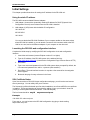
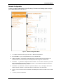
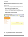
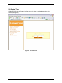
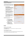
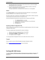
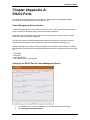
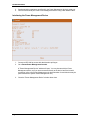
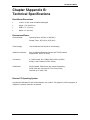
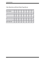
Master-IP DR-1000 User Manual Version 2.0.1 ConnectPRO D i g i ta l R e m o t e K V M S o l u t i o n s DR-1000 © ConnectPRO 20525 Paseo Del Prado Walnut, CA 91789 Phone (909) 444-9288 • Fax (909) 444-9289 Email: [email protected] Corporate Web Site: www.ConnectPRO.com Version 2.0.1 DR-1000 User Manual About this Document This document provides installation and operation instructions for ConnectPRO’s DR-1000. It is intended for system administrators and network managers, and assumes that readers have general understanding of networks, hardware and software. All information in this document is subject to change without prior notice. Copyright Copyright © 2005 ConnectPRO, a GemTek Technolgy company, USA DR-1000 is a registered trademark of ConnectPRO. All rights reserved. All other marks are trademarks or registered trademarks of their respective owners Page 2 DR-1000 User Manual DR-1000 User Guide.......................................................................................................................... 1 Chapter 1 : Introduction ...................................................................................................................... 5 Overview ...................................................................................................................................... 5 Key Features................................................................................................................................ 5 Terminology Used in This Guide ................................................................................................ 5 Chapter 2 : Installation........................................................................................................................ 6 Getting Started............................................................................................................................. 6 Back Panel Description ............................................................................................................... 8 Front Panel Description............................................................................................................... 9 Initial Settings............................................................................................................................... 9 Chapter 3 : Remote Operation......................................................................................................... 14 Remote Operational Flow .................................................................................................. 14 Operation through the Local Console................................................................................ 14 Getting Started........................................................................................................................... 14 Using the Toolbar....................................................................................................................... 14 Information Displayed in the Toolbar................................................................................. 15 Initial Settings at the Remote PC .............................................................................................. 15 Global Settings for Target Servers .................................................................................... 15 Individual Settings for Each Target Server........................................................................ 15 Connecting to a Target Server.................................................................................................. 15 Switching Between Target Servers ................................................................................... 16 Taking Over a Remote Session......................................................................................... 16 Synchronizing Mouse Pointers ................................................................................................. 16 Align..................................................................................................................................... 16 Calibrate.............................................................................................................................. 17 Manual Settings of the Mouse Pointers ............................................................................ 17 Advanced – Mouse Emulation........................................................................................... 17 Keyboard Sequences................................................................................................................ 18 Reset .......................................................................................................................................... 18 Soft Reset with ‘Ctrl-Alt-Del’............................................................................................... 18 Hard Reset............................................................................................................................... Power Management Console ............................................................................................ 18 Refresh....................................................................................................................................... 19 Settings....................................................................................................................................... 19 Colors .................................................................................................................................. 19 Users ................................................................................................................................... 19 Servers................................................................................................................................ 20 Video Adjustments.............................................................................................................. 20 Manual Video Adjustment.................................................................................................. 20 Tips and Hints for Manual Video Adjustment.................................................................... 21 Performance ....................................................................................................................... 21 Switch.................................................................................................................................. 22 Console ............................................................................................................................... 22 Verifying DR-1000 Version........................................................................................................ 22 Page 3 DR-1000 User Manual Chapter 4 Appendix A: RS232 Ports............................................................................................... 23 Power Management Device Interface............................................................................... 23 Chapter 5 Appendix B: Technical Specifications ............................................................................ 25 Chapter 6 Regulatory Information.................................................................................................... 27 Page 4 DR-1000 User Manual Chapter 1: Introduction Overview The ConnectPRO Remote DR product line provides the full power and capability of a local operator’s keyboard, video, and mouse interface – remotely. The DR-1000 is a hardware device typically installed in a rack alongside servers. It can interface with a server directly, or with a group of servers through analog KVM switches. By digitizing the KVM signals it allows anytime access to servers in all scenarios (BIOS, Pre-boot, blue-screen, etc.) regardless of their state, operating system, or server vendor. Key Features BIOS Level access Since the DR – series products provide hardware level access, they still provide remote console access outside of any operating system, even at the BIOS or command-line levels. Total Compatibility As the DR product does not require software to be installed on any target system (or client system for that matter), compatibility is ensured with any Windows, Linux, or Unix server operating systems. Inside the DR-1000 is also a database of over 100 KVM switches to ensure compatibility with any existing KVM switch you may have installed. High Security Built in IPSec (up to 3DES encryption), TCP/IP ports are configurable to match any Firewall scheme. Web-based Access Browser access to a target server, from any location via secured standard IP connection. Compatible with any Windows Internet Explorer version 5.0 and above. Terminology Used in This Guide Target Server - The computer/server that is accessed remotely via the DR-1000. Remote PC - The PC used to connect remotely to the DR-1000. DR-1000 Toolbar Menu - Toolbar Menu displayed at the Remote PC, facilitating control and adjustments of DR-1000 operations. Target Server Pointer - Mouse pointer of the Target Server. DR-1000 Pointer - Local mouse pointer on the Remote client PC. The Target Pointer should be aligned with the DR-1000 Pointer Remote Session - The process of accessing and controlling Target Servers connected to DR-1000 from a Remote PC. Page 5 DR-1000 User Manual Chapter 2: Installation Getting Started This chapter will walk you through the installation of your DR-1000 unit. Supplied with the DR-1000 unit Before you begin - ensure that you have all the necessary items listed below for proper installation: 1. DR-1000 – to - KVM cable with Mouse, Keyboard and Video connectors on one end and male HDB15 connector on the other end 2. One RS232 RJ45 cable to interface between DR-1000 and optional serial manageable network devices 3. Rack-mount Kit (for mounting the DR-1000 in the rack) Hardware Connections 1. Attach the all-in-one KVM (keyboard, mouse, video) cable to the DR-1000’s Video/Input KVM connectors on one side, and the corresponding KVM connectors on the opposite end of the cable to a target system / KVM switch. 2. For the Local operation with the KVM switch and Servers, connect a physical Keyboard, Mouse and Video display to DR-1000’s Local Console connectors. 3. Attach DR-1000 to your network using one of the two LAN interfaces on the DR-1000 back panel; See Initial Settings Note: The Ethernet connectors on the DR-1000 back panel are standard RJ-45 connectors of 10/100 Mbps. 4. (If connecting to a KVM switch) Populate the KVM switch with Target Servers that will be controlled by DR-1000. Page 6 DR-1000 User Manual Figure 1: DR-1000 hardware connection Page 7 DR-1000 User Manual Back Panel Description H F E A B LAN1 Serial 1 Monitor LAN2 Serial 2 I G KVM Local Console D C Figure 2: DR-1000 Back Panel A IEC Connector - For connecting a suitable power cord. B, C, D Local console KVM Connectors - Connections to physical Keyboard, Mouse and Video display for the DR-1000 Local Operation as a pass-through port to the connected KVM switch. E Video/Input KVM connectors - Keyboard, Mouse and Video connections for DR-1000 Remote Operation. These connectors should be connected to the KVM switches corresponding connectors. F, G RS232 - Connection to a Power Management unit / Network Devices. (For use with provided RJ-45 to DB-9 Serial Cable) H, I 10/100 Mbit Ethernet connections. (For connection to the LAN/WAN) Page 8 DR-1000 User Manual Front Panel Description B A C Go Local Remote Power Reset D Figure 3: DR-1000 Front Panel A Power LED Indicator - Turns ON when DR-1000 is powered on. B Remote LED Indicator - Turns ON when remote session is active. C Go Local Button - When pressed, DR-1000 immediately disconnects the Remote PC’s link to the Target PC, and the Local Mouse and Keyboard become operational. D Reset button – Press this button to restart DR-1000 unit (Note: This will also disconnect any remote users) Page 9 DR-1000 User Manual Initial Settings This chapter provides instructions for setting the IP address for the DR-1000 unit. Using the static IP address The DR-1000 has two available Ethernet Adapters: 1. LAN Adapter 1 boots with a dynamically obtained IP address if a DHCP (Dynamic Host Configuration Protocol) server exists where the DR-1000 is installed 2. LAN Adapter 2 (VPN) boots with the default IP configuration: 192.168.0.155 255.255.255.0 192.168.0.1 You can use the default DR-1000 IP address if your computer resides on the same subnet where DR-1000 is installed, or you can attach a crossover LAN connector cable to the DR1000 on one end, and to the Ethernet adapter of your computer on the other end. Launching the DR-1000 web configuration interface Complete the initial setup by modifying the DR-1000 configuration via its web configuration interface: 1. Launch the web browser (Internet Explorer version 5.0 or higher) 2. Type the IP address of the DR-1000 system in the address field (e.g. https://192.168.0.155/config) (Note that the Configuration Page must use Secure HTTP) 3. Press Enter 4. Type a user name and password for the DR-1000 system when prompted. By default, the user name and password are: admin – cpremote (case sensitive) 5. Press Enter. The web interface launches. It may take a few seconds for the navigation area to appear. 6. Bookmark the page for easy reference in the future. SSL Certificate Notes: Upon first connection to DR-1000’s https configuration web page, you will receive two browser security warnings. You can safely click yes to continue. The first warning will be eliminated upon first client installation, once ConnectPRO’s root certificate is installed. The second warning can be avoided by adding a line to your window’s ‘hosts’ file (usually at “\winnt\system32\drivers\etc\hosts”. Edit with Notepad.) The line format should be: any-IP any-name.ceo-ip.net Example: 192.168.0.155 main.ceo-ip.net From now on, you can browse to the DR-1000 configuration by typing or book-marking https://main.ceo-ip.net. Page 10 DR-1000 User Manual Network Configuration Consult your Network Administrator for the IP settings. Proceed to the following steps to configure your network parameters (See figure 1) Figure 1: Network Configuration Menu 1. To configure the Network settings you will click on “Network Configurations” 2. DEVICE NAME – Type in a designated device name for the DR-1000. 3. FIRST TCP PORT – Choose three consecuritve ports, and enter the first port of the series. For remote access from a secured LAN, the selected ports should be open for communication 4. ADAPTER 1 – By default this adapter has DHCP enabled. You can clear the checkbox if you would like to manually assign the network address information. This will disable the ability to obtain an IP address from a DHCP server on your LAN. 5. ADAPTER 2 – By default this unit is set to a private IP address. You can reconfigure this to use a different private IP address, or a public IP address to enable access from the outside. 6. Unless you are connected to the ConnectPRO Central Management Server, DO NOT click to enable CMS. 7. To finish, click “Save and Restart” Page 11 DR-1000 User Manual Consult your Network Administrator regarding the use of the DHCP. Note: Navigating between the main configuration menu’s will save the given parameters. To complete the operation on the DR-1000 machine, press “Save and Restart”. Firmware Upgrade Upgrading to the DR-1000’s latest firmware is periodically necessary to take advantage of new features as they are added. 1. Preparations: Obtain the updated Firmware version from ConnectPRO, and copy it into a local folder on the PC where the web configuration interface is launched. 2. On the DR-1000 web configuration interface, select the Firmware Upgrade option from the main menu on the left side. Browse to located the upgrade file (See figure 3) 3. After uploading the upgrade file the system will prompt you to start the upgrade procedure. Click the “Start Upgrade” button. 4. Upon the upgrade completion, the system will prompt you to return “Back” to the main menu. Press “Save and Restart” to complete the upgrade procedure. Figure 3: Firmware Upgrade NOTE: From time to time the upgrade procedure will fail. If this happens just re-upload the firmware and try again. Page 12 DR-1000 User Manual Set System Time On the DR-1000 web configuration interface select this option to set the date and time of the device. (See figure 4) Figure 4: Set system time Page 13 DR-1000 User Manual Chapter 3: Remote Operation This chapter will provide detailed explanations about Remote Operation and walk you through the various features and options provided by the DR-1000. As soon as a Remote PC is connected, the DR-1000 begins remote operation. Remote Operational Flow 1. The DR-1000 receives Mouse and Keyboard signals from the Remote PC. 2. DR-1000 transmits these signals to the KVM Mouse and Keyboard ports - as if physical devices were directly attached. 3. The resulting Video images are received by DR-1000, processed, compressed, filtered, and transmitted back to the Remote PC to reflect the activity done by that Remote PC. In remote operation the Remote LED on the DR-1000 will be lit and the three LEDs on the Local Console keyboard will flash to indicate that a user is connected remotely. Operation through the Local Console In cases where regular KVM functionality is required, the DR-1000 provides a transparent solution. Connecting local mouse, keyboard and video to the DR-1000’s Local Console connectors enables you to operate the KVM switch and the attached Servers / or just a server locally, as if these devices were directly connected to it. Getting Started, Remotely To commence Remote Operation and run Remote Sessions with Target Servers, you need to open an Internet Explorer window at a Remote PC and link to the DR-1000 unit. A Remote Session can be executed on a Microsoft Windows machine running Internet Explorer 5.0 and above. 1. Type the DR-1000’s IP address in the Internet Explorer Address Bar. For example: http://192.168.0.155 Enter. Note: This part of the Installation requires ActiveX controls to be downloaded to the Remote PC. This requires the user to be logged-on to the PC as a user with full administrative rights. 2. The DR-1000 screen is displayed. The Toolbar is displayed on the top/left side. 3. To start a remote session, click the Connect Button. 4. Type in the DR-1000’s default Username and Password: ‘admin’ and ‘cpremote’, respectively (both are case sensitive). The screen of the Target Server connected directly to DR-1000, or the Server currently selected on the KVM switch – will be displayed within the Internet Explorer frame. Using the Toolbar By operating the DR-1000 Toolbar Menu, you can control DR-1000 operations, as described hereafter and throughout this Guide. You can close the DR-1000 Toolbar whenever convenient: either by double-clicking the DR-1000 Tray Icon (left to the clock at the bottom right of the screen), or by pressing the F9 Function key. Page 14 DR-1000 User Manual The F9 and the Tray Icon double-clicking, operate as toggles - if the Toolbar Menu is currently displayed it will disappear, and if it is not displayed it will reappear. Information Displayed in the Toolbar Current Server – the Target Server currently active on a Remote Session with the Remote PC. RTT – Round-trip-time. The time it takes, (in milliseconds) for a packet to travel from the Remote PC to the DR-1000 and back. (RTT measurement is ICMP based, similar to the 'Ping'. Note that if Ping is blocked, the RTT will show a Timed Out value as well). Initial Settings at the Remote PC Except for settings performed via the DR-1000 web configuration interface, all other DR-1000 settings are performed at the Remote PC. This section outlines the sequence and elements that should be set for proper remote operation. References to detailed explanations are provided. Global Settings for Target Servers 1. Choose the KVM Switch brand and model through which the Target Servers are linked to DR-1000. (This configuration is accessed through the toolbar’s Settings / Switch menu detailed on p. 23) 2. Determine and apply Server names to Target Servers that are controlled by DR-1000 via the KVM switch. (This configuration is accessed through the Settings / Servers menu detailed on p. 21) When Switch and Servers are configured, you will be able to switch between Target Servers and perform other settings or remote operations for each individual Target Server. Individual Settings for Each Target Server 1. Switch to the Target Server you want to set. 2. Adjust the Video Image of the Target Server 3. Calibrate the Mouse speed characteristics of the Target Server Note: Video Adjustment and Mouse Pointer Synchronization, should be performed only once per Target Server, and are linked to each other (i.e. mouse pointers may not synchronize if the Video Adjustment was not performed for a certain Target Server). 4. Perform Steps 2 and 3 for each Target Server controlled by DR-1000 Connecting to a Target Server 1. Select the Connect Button. A Login box is displayed, where a Username and Password should be typed (both are case sensitive). 2. You may apply Bandwidth characteristics to the connection, by selecting “Low” or “High” (refer to “Settings“ for Colors and Performance settings). 3. “Low” will apply 16 colors, low bandwidth, high compression. 4. “High” will apply high colors, high bandwidth, low compression. Page 15 DR-1000 User Manual 5. The default Bandwidth characteristics (if nothing is selected), are those used in the last connection. 6. Press OK. The screen of the last Target Server controlled by DR-1000 will be displayed within the Internet Explorer frame. The Connect symbol will change to Disconnect. When a Secured connection is established, a Lock symbol is displayed over the Connect/Disconnect symbol. Switching Between Target Servers To switch from one Target Server to another: 1. In the Toolbar, go to Server. 2. Select a specific Server from the displayed list. 3. DR-1000 will switch to the selected server. Taking Over a Remote Session A user may start a Remote Session and cancel a session executed by another user. This operation is allowed only when the user’s privileges are equal or higher than the privileges of the user running the current session. An appropriate warning message is displayed to the user before the actual takeover is performed. Note: User privileges are determined in Settings>Users. Synchronizing Mouse Pointers When working at the Remote PC, two mouse pointers are displayed: (1) the Remote PC’s pointer; which is large and transparent and (2) the smaller one that represents the pointer of the Target Server. You’ll see the two pointers whenever your mouse pointer is inside the screen area of the Target Server. Each Server may have its own mouse characteristics (i.e. the speed at which the pointer moves), thus you will have to synchronize them. In order to synchronize both mouse pointers: 1. In Manual Settings, verify that the correct Operating System is selected (see below). For most operating systems this should be sufficient and the mouse pointers should be synchronized. 2. If the mouse pointers are not synchronized, execute the Calibrate function, or manually adjust the mouse acceleration listed under “Manual Settings” if the calibrate does not work. For the initial configuration it may take some tinkering or adjusting to find the right settings, however this should only need to be performed once per Target Server. Align In some cases, the Mouse Pointers may go out-of-sync. Misalignment might occur during or after a Logon sequence to the Target Server. To re-synchronize the Mouse pointers – select Align, or press Ctrl+M keys simultaneously. If the mouse acceleration seems accurate but it’s just not aligned – try the “Video” > “Auto Adjust” feature Page 16 DR-1000 User Manual Calibrate For Windows NT, Windows 9x/Me, or Windows 2000 Calibrate automatically discovers the mouse speed characteristics of the Target Server. At the end of this short process, the two pointers will be aligned, and DR-1000 will save the speed characteristics of the specific Target Server. Calibration is required only once per Target Server. If the Video Noise Level is not zero, calibration may not succeed. In this case, go to Video Adjustment and eliminate the noise, then return to perform Mouse Calibrate. For SCO Unix, Linux and SUN Solaris Select the Mouse Manual Settings as described below. Manual Settings of the Mouse Pointers Use Manual Settings to configure the Mouse speed characteristics of Target Servers manually. 1. 2. Go to Mouse>Manual Settings in the Toolbar. Select the Operating System running on the Target Server. Once selected, the system will present the same Acceleration and Threshold Sliders that are equivalent to the Mouse settings Sliders of the Target Servers Operating System. Note that the Calibration algorithm is dependent on the Operating System selected here. 3. 4. Set the Sliders to the same values as set in the Target Server’s Mouse Properties window, or select Default if Mouse Properties were never changed for the Target Server. Use Old Protocol – This option is available only for unsupported operating systems and SUN Solaris. Use this option only if you are sure of the custom acceleration algorithm you are using, or have been told to do so by customer support.. Advanced – Mouse Emulation By using the Advanced Mouse settings, you can forcefully set the type of mouse that you would like DR-1000 to emulate. It is recommended that you will not change the advanced settings unless you are experiencing erratic mouse behavior (the mouse is making random clicks and jumping arbitrarily around the screen). When setting the mouse emulation type, set it to match the mouse connected to the Local Console port on the DR-1000, e.g. If the local mouse is a 2 button mouse, but not from Microsoft, set the Mouse Emulation type to "Standard Mouse" and make sure the "Microsoft Mouse" box is unchecked. Max Rate option defines the maximum mouse report rate. Note that for Sun Solaris the default value is 20 in order to support older Sun versions. Switch Acceleration - In some KVM switch brands (for example G&D, Rittal), the switch accelerates the mouse on top of the acceleration provided by the operating system. If necessary, check this option to compensate (decelerate) switch acceleration and achieve full synchronization. Page 17 DR-1000 User Manual Keyboard Sequences You may define Keyboard Sequences that DR1000 will transmit directly to Target Servers, and will not be processed by the Remote PC itself. In the Toolbar select Keyboard>Add/Remove to update the list of operational Key Sequences, or Select a Key from the list to transmit it to the Target Server as if this Key Sequence was typed by you at the Target Server Keyboard. When Add/Remove is selected, a ‘Special Key’ window is displayed. You may add to the list a Predefined Key Sequence, Record a new key sequence, or Edit/Delete an existing one. To Record or Edit a Key Sequence, press Start Recording. Every key that you press until Stop Recording is pressed will be recorded to generate the desired Key Sequence. If, for example, you want to have an Alt+F4 function in your Keyboard list: 1. 2. 3. 4. 5. 6. Select the Record New. Label the Key Sequence. Press Start Recording. Press the Alt key, press and release the F4 key, release the Alt key. Click Stop Recording. Press Apply. The new Keyboard Sequence will appear in the Keyboard list. Reset Soft Reset with ‘Ctrl-Alt-Del’ Select Ctrl-Alt-Del to send this three Key sequence to the Target Server to initiate its Shutdown/Login process. Power Management Console The Power Management Console can be accessed when the Power Management Console is activated. Only users with Administrative privileges can access it. Page 18 DR-1000 User Manual When selected, the "Power Management Device" window opens, displaying the serial interface with the Power Management device. (Refer to “Power Management device Interface” for the activities that may be performed while interfacing a Power Management unit). Refresh Select Refresh or press Ctrl+R to refresh the Video image. Refresh may be needed when changing the Display attributes of a Target Server. Settings When selecting Settings, a pull down menu with the following options is displayed Colors Select Colors to set the color depth (16, 256 or High) for the connection between DR-1000 and the Remote PC. The color depth chosen determines the amount of color data DR-1000 delivers to the Remote PC. High Color will show more vibrant color, but may slow performance. 16 color will maximize the speed of DR-1000’s performance. Users Initially, DR-1000 comes with one default user - admin with the password cpremote. This user is provided administrative privileges, and cannot be deleted from the Users list. Select Users to Edit, Remove or Add DR-1000 users. To add a new user, do the following: 1. 2. 3. 4. In the toolbar, go to Settings>Users>Edit Users and press Add. Type in the new user name and password. Turn off the “Administrative Rights” checkbox, if so required. Press OK to save. User Privileges DR-1000 supports two levels of Users: with or without Administrative Privileges. User with administrative privileges has access to all facilities described in this Guide (with exception to the serial configuration through hyperterminal). User without administrative privileges will not have access to the following options: Mouse – Manual Settings>Advanced Reset – Hard Reset, Power Management Page 19 DR-1000 User Manual Settings – Users>Edit Users, Server, Video Adjustments, Switch Recording, Power Management Servers Use Server Settings to apply names to the Target Servers attached to the KVM ports. Note that Target Servers that are labeled “UNUSED” cannot be remotely accessed. Assign names to target servers that are linked to the KVM switch. 1. 2. 3. 4. 5. In the Toolbar, go to Settings>Servers. Press Select Server. A list of servers is displayed. Initially, the first server is called "Server1", and the others are named “UNUSED”. Click one of the Target Servers in the list, assign a new name and press Apply. Continue to assign names to all attached servers. Press OK. The new names are now indicated in the list of servers. Video Adjustments In most cases, Target Servers require video adjustments. This procedure is performed once for each Target Server and for each Windows Resolution. The auto video adjustment process is performed automatically by selecting Video>Auto Adjust. Note: During Auto Adjustment process, an indicator bar will show the tune-up progress. If that process is runs more then 3 times, which would indicate abnormal noise level, check the video cable and verify that no dynamic video application is running on the target server’s desktop. During Auto Adjustment process, the background freezes. Upon completion, the video will be tuned up properly It is recommended to open windows explorer in the background. In full-screen DOS mode, perform a manual video adjustment. All video adjustments are per Target Server Manual Video Adjustment The Video Adjustments configuration window has slider controls, by which you may adjust the sampled Server's picture for optimal results. When selecting Video Adjustment, a red frame is displayed around the Server's screen. This frame represents the screen area according to the Server's screen resolution. Adjustments should be performed inside and relative to this frame. You may choose to select manual video adjustment in case you want to fine-tune the video according to your needs (such as increasing the brightness level) Video Adjustment Sliders and Controls Page 20 DR-1000 User Manual Brightness - controls the brightness of the displayed image. Contrast - controls the contrast of the displayed image. Scale - defines the width of the captured image. Horizontal Offset - defines the starting position of each line on the displayed image. Vertical Offset - defines the vertical starting position of the displayed image. Phase - defines the point at which each pixel is sampled. Black level - controls black level clamping, i.e. the position at which the input signal is sampled for determining the black level of the displayed line. The brightness of each sampled pixel is relative to this Black Level value. Filter - set the Filter to the lowest level possible, provided that the Noise Level is kept as low as possible. Noise Level - represents the Video "noise" when a static screen is displayed. Tips and Hints for Manual Video Adjustment Video adjustments should be performed on a static screen. It is considered optimal when the video image is located correctly within the surrounding red frame, the colors of the captured image are satisfactory, and the Noise Level is minimal - preferably zero. 1. First, adjust the Horizontal Offset, the Vertical Offset and the Scale – so the captured video image is fully visible and adjusted to the surrounding red frame. Start by adjusting the Horizontal Offset to the left. Slowly click (don’t pull) the Horizontal slide with the Arrow keys until it overlaps the left side of the red frame. Perform the same for the Vertical Offset. Move the Scale until the right/bottom side is adjusted to the red frame. Then, try to achieve minimal Noise Level by fine-tuning the Scale. When Noise is minimal, adjust the Phase and the Filter – until the Noise Level is zero. You may adjust the Brightness and Contrast until the obtained colors are satisfactory. In most cases there is no need to change the original value of the Black Level. However, if Black Level adjustment is required, click the right arrow until the screen becomes corrupted, and then click four times the left arrow. Press Apply after each setting. At the end press OK to save. 2. 3. 4. 5. 6. How to use the adjustment sliders Click the slider of the control you want to change. The selected control becomes active. As you move the slider the displayed image will change. Use the mouse to move the slider for coarse adjustment, and click the arrow keys for fine-tuning. Performance Select Settings>Performance to configure the characteristics of the Link to the DR-1000 machine. Page 21 DR-1000 User Manual For optimal performance while working in-band (LAN connection), select Non-Adaptive High-Bandwidth and Low-Compression. For optimal performance while working out-of-band (Dialup connection), select NonAdaptive Low-Bandwidth and High-Compression. For improved performance, verify that the Colors selection is a 16 colors palette. Switch Select Settings>Switch to choose the KVM switch attached to DR-1000. You may change the selected KVM switch at run time without the need to reconnect. DR-1000 is shipped with no KVM switch selected (None is selected). When no Switch is selected, remote sessions can be performed with one Target Server only. Select the KVM Switch through which the target servers are connected to the DR-1000. 1. 2. 3. 4. Click Settings>Switch in the toolbar. In the Dialog box select the manufacturer of your KVM switch. Double-click the KVM model. Press OK to save. Importing a Switch Configuration File Switch Configuration files (provided by ConnectPRO) are updated regularly to allow for the support of additional KVM switches. To import an updated switch configuration file, perform the following: 1. 2. 3. 4. Obtain the new Switch Configuration file from ConnectPRO. Copy it into a local folder in the Remote PC. Type its path or “Browse …” to the file you want to import. To complete the task, click Import. You may import Switch Configuration Files at run time without the need to reconnect. Console Select this option to open the Power Management settings configuration window. Refer to Power management device interface for more information. Verifying DR-1000 Version To verify the Firmware, KME (Keyboard/Mouse Emulation firmware) and Switch Configuration File versions installed on your DR-1000, as well as ConnectPRO’s contact information - select the About Button. Page 22 DR-1000 User Manual Chapter 4Appendix A: RS232 Ports DR-1000 has two RS232 links, RJ45 connectors, for connecting serial manageable network devices such as Power Management units; Routers, etc) Power Management Device Interface A Power Management device provides the means to turn On or Off Target Servers connected to it. It has a number of individually (relay) controlled AC power receptacles. Depending on its characteristics, such a device may also allow you to monitor current, voltage, power, temperature, and other capabilities. DR-1000 can control most Power Management devices via its Serial Port. Setup and control is performed at the Remote PC, and is granted to users with administrative privileges only. DR-1000 is designed to control any Power Management device with a serial interface. Two Power Management devices that have been physically tested and verified to operate with DR-1000 to date are: • • • • WTI’s RPB+ WTI’s NPS BayTech's RPC22 APC's MasterSwitch, model AP9212 Setting Up the RS232 Port for Power Management Device 1. 2. From a Remote PC, connect to DR-1000 as a user with administrative privileges. Go to Settings>Power Management. Page 23 DR-1000 User Manual 3. 4. Set the serial link parameters as defined for the Power Management device's serial port. Link DR-1000's serial port to the Power Management device using a Null Modem cable. Interfacing the Power Management Device 1. 2. Connect to DR-1000 as a user with administrative privileges. Go to Reset>Power Management Console. A "Power Management Device" window will open. You may interact with the Power Management device, as if you were connected directly to the device itself via its serial connection (refer to the Power Management unit documentation for activities that may be performed with the specific Power Management unit). 3. Page 24 Close the "Power Management Device" window when done. DR-1000 User Manual Chapter 5Appendix B: Technical Specifications Rack Mount Dimensions • 2 Unit in 1U slot, clear front/back cables path • Height: 1.75" (44.45 mm) • Width: 6.7" (172 mm) • Depth: 9.1" (233 mm) Environment/Power Environmental: Operating Temp: 41F(5C) to 122F(50C) Storage Temp: -4F(-20C) to 122F (50C) Power Supply: 100-120/200-240 VAC 50-60 Hz Auto Sensing Network Connection: Dual 10/100 Base Ethernet Interface with TCP/IP protocol. Supports NAT and HTTP Proxy. Connectors: 2 * RJ45 Female, RJ11, DB25, DB9, KVM-in (2x PS/2, SVGA), Local Console (2x PS/2, SVGA) KVM Switch: PS/2 Keyboard, PS/2 Mouse (any mouse acceleration), SVGA Video any color scheme, True Color (24 bit), resolution up to 1024 x 768. Remote PC Operating System Any Microsoft Windows PC with Internet Explorer 5.0 or above. The support of 128 bit encryption is required if a secured connection is selected. Page 25 DR-1000 User Manual Video Resolution and Refresh Rates (Target Server) 56Hz 60Hz 66Hz 70Hz 72Hz VESA 640x480 VESA 800x600 x 85Hz x x x x x x x x VESA 820x464 x x x x VESA 1152x960 x x x VESA 1280x860 x VESA 1280x1024 x VESA 1600x1200 x Page 26 75Hz x VESA 720x400 VESA 1024x768 73Hz x x x x x x x DR-1000 User Manual Chapter 6 Regulatory Information Limited Warranty ConnectPRO , warrants to the original customer or the other end-user purchaser that this product is free from defects in materials or workmanship for a period of one year from the date of purchase. During the warranty period, and upon proof of purchase, the product will be repaired or replaced (with the same or similar model) at our option, without charge for either parts or labor. This warranty shall not apply if the product is modified, tampered with, misused, or subjected to abnormal working conditions (including, but not limited to lightning and water damage). Repair or replacement as provided under this warranty is the exclusive remedy of the purchaser. This warranty is in lieu of all other warranties, expressed or implied, including any implied warranty of merchantability or fitness for a particular use or purpose, and ConnectPRO shall in no event be liable to purchaser for indirect or consequential damages of any kind or character. Some states do not allow the exclusion or limitation of incidental or consequential damages or allow limitations on how long an implied warranty lasts, so the above limitations or exclusion may not apply to you. This warranty gives you specific legal rights, and you may also have other rights that vary from state to state. Declaration of Conformity This device is in compliance of the following standard specifications: • FCC Part 15, Subpart B, Class B (emission) • EN 55022 Class B (emissions) • EN 300 386 (immunity) Page 27