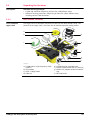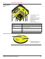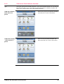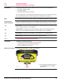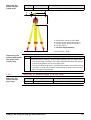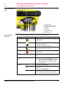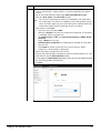
1
Leica iCON gps 60 User Manual Version 2.0 English Introduction Purchase Congratulations on the purchase of a Leica iCON gps 60 system. This manual contains important safety directions as well as instructions for setting up the product and operating it. Refer to "1 Safety Directions" for further information. Read carefully through the User Manual before you switch on the product. Product identification The type and serial number of your product are indicated on the type plate. Always refer to this information when you need to contact your agency or Leica Geosystems authorised service workshop. Trademarks • Windows is a registered trademark of Microsoft Corporation in the United States and other countries • CompactFlash and CF are trademarks of SanDisk Corporation • Bluetooth® is a registered trademark of Bluetooth SIG, Inc. All other trademarks are the property of their respective owners. Validity of this manual Available documentation This manual applies to the Leica iCON gps 60 SmartAntenna. Name Description/Format Leica iCON gps Provides an overview of the product together with tech- 60 Quick Guide nical data and safety directions. Intended as a quick reference field guide. Leica iCON gps All instructions required in order to operate the product 60 User Manual to a basic level are contained in the User Manual. Provides an overview of the product together with technical data and safety directions. Refer to the following resources for all Leica iCON gps 60 documentation/software: • the Leica USB documentation card • https://myworld.leica-geosystems.com myWorld@Leica Geosystems (https://myworld.leica-geosystems.com) offers a wide range of services, information and training material. With direct access to myWorld, you are able to access all relevant services whenever it is convenient for you, 24 hours a day, 7 days per week. This increases your efficiency and keeps you and your equipment instantly updated with the latest information from Leica Geosystems. Service Description myProducts Add all Leica Geosystems products that you and your company own. View detailed information on your products, buy additional options or Customer Care Packages (CCPs), update your products with the latest software and keep up-to-date with the latest documentation. myService View the service history of your products in Leica Geosystems Service Centres and detailed information on the services performed on your products. For your products that are currently in Leica Geosystems Service Centres view the current service status and the expected end date of service. iCON gps 60, Introduction 2 Service Description mySupport Create new support requests for your products that will be answered by your local Leica Geosystems Support Team. View the complete history of your Support and view detailed information on each request in case you want to refer to previous support requests. myTraining Enhance your product knowledge with the Leica Geosystems Campus - Information, Knowledge, Training. Study the latest online training material or download training material on your products. Keep upto-date with the latest News on your products and register for Seminars or Courses in your country. myTrustedSer- Offers increased productivity while at the same time providing vices maximum security. • myExchange With myExchange you can exchange any files/objects from your computer to any of your Leica Exchange Contacts. • mySecurity If your instrument is ever stolen, a locking mechanism is available to ensure that the instrument is disabled and can no longer be used. iCON gps 60, Introduction 3 Table of Contents In this manual Chapter 1 Safety Directions 1.1 1.2 1.3 1.4 1.5 1.6 1.7 2 2.3 2.4 System Components Unpacking the Container 2.2.1 Base Station Container 2.2.2 Rover Setup Container Instrument Components Compatible Field Controllers 2.4.1 Available Field Controller 2.4.2 Holder and Clamps for Field Controllers 2.4.3 iCON Series Field Software Overview Using the iCON gps 60 SmartAntenna 3.1 3.2 3.3 3.4 3.5 3.6 3.7 3.8 3.9 4 General Introduction Definition of Use Limits of Use Responsibilities Hazards of Use Electromagnetic Compatibility EMC FCC Statement, Applicable in U.S. Description of the System 2.1 2.2 3 Page Power Supply Batteries 3.2.1 Installing the Internal Battery 3.2.2 General Battery Handling Installing a SIM Card Slot-in-Device External Radios Using USB Memory Devices Installing Adapters Installation on a Machine Antenna Heights 3.9.1 Understanding Antenna Heights 3.9.2 The Mechanical Reference Plane, MRP 3.9.3 Measuring the Antenna Height for a Pillar Setup 3.9.4 Measuring the Antenna Height for a Tripod Setup 3.9.5 Measuring the Antenna Height for a Pole Setup Setups with Accessories 4.1 4.2 4.3 4.4 4.5 4.6 4.7 iCON gps 60, Table of Contents Real-Time Base Setup Local Base Station Setup with External GNSS Antenna Real-Time Base with Raw Data Logging Raw Data Logging Setup Real-Time Rover Setup Setup for Machine Use Establish Bluetooth Data Connection 7 7 8 8 8 9 12 13 15 15 18 18 21 22 23 23 24 26 27 27 28 28 28 29 30 30 31 32 33 34 34 34 35 37 38 39 39 40 42 43 44 45 46 4 5 iCON gps 60 SmartAntenna User Interface 5.1 5.2 5.3 6 Software Tools 6.1 6.2 6.3 6.4 6.5 6.6 6.7 7 Transport Storage Cleaning and Drying Technical Data 9.1 9.2 9.3 9.4 10 Overview Coordinate System Conversion Care and Transport 8.1 8.2 8.3 9 Base Setup 6.1.1 Base Setup Description 6.1.2 Manual Base Setup 6.1.3 Base Setup using BasePilot Rover Setup ORP and NMEA Output Raw Data Logging iCON Telematics Import, Export, or Delete Data Licensing Coordinate Systems 7.1 7.2 8 User Interface Description Main Menu Submenus 5.3.1 Navigation in Submenus 5.3.2 How to Change Settings and Edit Values 5.3.3 Available Sub Menus Technical Data iCON gps 60 SmartAntenna 9.1.1 Tracking Characteristics 9.1.2 Accuracy 9.1.3 General Technical Data of the Instrument Antennas Technical Data Pin Assignments and Sockets Conformity Declarations 9.4.1 iCON gps 60 9.4.2 GFU14, SATEL Satelline 3AS, GFU27, SATEL Satelline M3-TR1 9.4.3 GFU15, Pacific Crest PDL 9.4.4 TFR-300L 9.4.5 CCD7 - SATEL TA13 9.4.6 Sierra MC8795V Software Licence Agreement iCON gps 60, Table of Contents 47 47 48 51 51 51 53 58 58 58 58 64 65 68 69 70 74 75 76 76 77 80 80 80 80 82 82 82 83 84 87 89 90 90 91 92 93 94 95 97 5 Appendix A NMEA Message Formats Overview Symbols Used for Describing the NMEA Formats GGA - Global Positioning System Fix Data GGK - Real-Time Position with DOP GGQ - Real-Time Position with CQ GLL - Geographic Position Latitude/Longitude GNS - GNSS Fix Data GSA - GNSS DOP and Active Satellites GSV - GNSS Satellites in View HDT - Heading, True LLK - Leica Local Position and GDOP LLQ - Leica Local Position and Quality RMC - Recommended Minimum Specific GNSS Data VTG - Course Over Ground and Ground Speed ZDA - Time and Date 98 98 98 101 102 103 104 104 106 107 109 110 111 112 113 114 Appendix B ORP – Orientation and Position 115 Appendix C Glossary 118 118 119 120 121 A.1 A.2 A.3 A.4 A.5 A.6 A.7 A.8 A.9 A.10 A.11 A.12 A.13 A.14 A.15 C.1 C.2 C.3 C.4 iCON gps 60, Table of Contents C G N W 6 1 Safety Directions 1.1 General Introduction Description The following directions enable the person responsible for the product, and the person who actually uses the equipment, to anticipate and avoid operational hazards. The person responsible for the product must ensure that all users understand these directions and adhere to them. About Warning Messages Warning messages are an essential part of the safety concept of the instrument. They appear wherever hazards or hazardous situations can occur. Warning messages... • make the user alert about direct and indirect hazards concerning the use of the product. • contain general rules of behaviour. For the users‘ safety, all safety instructions and safety messages shall be strictly observed and followed! Therefore, the manual must always be available to all persons performing any tasks described herein. DANGER, WARNING, CAUTION and NOTICE are standardized signal words for identifying levels of hazards and risks related to personal injury and property damage. For your safety it is important to read and fully understand the table below with the different signal words and their definitions! Supplementary safety information symbols may be placed within a warning message as well as supplementary text. Type DANGER WARNING CAUTION NOTICE iCON gps 60, Safety Directions Description Indicates an imminently hazardous situation which, if not avoided, will result in death or serious injury. Indicates a potentially hazardous situation or an unintended use which, if not avoided, could result in death or serious injury. Indicates a potentially hazardous situation or an unintended use which, if not avoided, may result in minor or moderate injury. Indicates a potentially hazardous situation or an unintended use which, if not avoided, may result in appreciable material, financial and environmental damage. Important paragraphs which must be adhered to in practice as they enable the product to be used in a technically correct and efficient manner. 7 1.2 Definition of Use Intended use • • • • • • Computing with software. Carrying out measurement tasks using various GNSS measuring techniques. Recording GNSS and point related data. Remote control of product. Data communication with external appliances. Measuring raw data and computing coordinates using carrier phase and code signal from GNSS satellites. Reasonably forseeable misuse • • • • • Use of the product without instruction. Use outside of the intended use and limits. Disabling safety systems. Removal of hazard notices. Opening the product using tools, for example screwdriver, unless this is permitted for certain functions. Modification or conversion of the product. Use after misappropriation. Use of products with recognisable damages or defects. Use with accessories from other manufacturers without the prior explicit approval of Leica Geosystems. Inadequate safeguards at the working site. Controlling of machines, moving objects or similar monitoring application without additional control- and safety installations. • • • • • • 1.3 Limits of Use Environment Suitable for use in an atmosphere appropriate for permanent human habitation: not suitable for use in aggressive or explosive environments. DANGER Local safety authorities and safety experts must be contacted before working in hazardous areas, or close to electrical installations or similar situations by the person in charge of the product. 1.4 Responsibilities Manufacturer of the product Leica Geosystems AG, CH-9435 Heerbrugg, hereinafter referred to as Leica Geosystems, is responsible for supplying the product, including the user manual and original accessories, in a safe condition. Person responsible for the product The person responsible for the product has the following duties: • To understand the safety instructions on the product and the instructions in the user manual. • To ensure that it is used in accordance with the instructions. • To be familiar with local regulations relating to safety and accident prevention. • To inform Leica Geosystems immediately if the product and the application becomes unsafe. • To ensure that the national laws, regulations and conditions for the operation of e.g. radio transmitters or lasers are respected. iCON gps 60, Safety Directions 8 1.5 CAUTION DANGER WARNING WARNING CAUTION WARNING DANGER Hazards of Use Watch out for erroneous measurement results if the product has been dropped or has been misused, modified, stored for long periods or transported. Precautions: Periodically carry out test measurements and perform the field adjustments indicated in the user manual, particularly after the product has been subjected to abnormal use and before and after important measurements. Because of the risk of electrocution, it is dangerous to use poles and extensions in the vicinity of electrical installations such as power cables or electrical railways. Precautions: Keep at a safe distance from electrical installations. If it is essential to work in this environment, first contact the safety authorities responsible for the electrical installations and follow their instructions. During dynamic applications, for example stakeout procedures there is a danger of accidents occurring if the user does not pay attention to the environmental conditions around, for example obstacles, excavations or traffic. Precautions: The person responsible for the product must make all users fully aware of the existing dangers. Inadequate securing of the working site can lead to dangerous situations, for example in traffic, on building sites, and at industrial installations. Precautions: Always ensure that the working site is adequately secured. Adhere to the regulations governing safety and accident prevention and road traffic. If the accessories used with the product are not properly secured and the product is subjected to mechanical shock, for example blows or falling, the product may be damaged or people can sustain injury. Precautions: When setting-up the product, make sure that the accessories are correctly adapted, fitted, secured, and locked in position. Avoid subjecting the product to mechanical stress. If the product is used with accessories, for example masts, staffs, poles, you may increase the risk of being struck by lightning. Precautions: Do not use the product in a thunderstorm. If the product is used with accessories, for example on masts, staffs, poles, you may increase the risk of being struck by lightning. Danger from high voltages also exists near power lines. Lightning, voltage peaks, or the touching of power lines can cause damage, injury and death. iCON gps 60, Safety Directions 9 Precautions: • Do not use the product in a thunderstorm as you can increase the risk of being struck by lightning. • Be sure to remain at a safe distance from electrical installations. Do not use the product directly under or close to power lines. If it is essential to work in such an environment contact the safety authorities responsible for electrical installations and follow their instructions. • If the product has to be permanently mounted in an exposed location, it is advisable to provide a lightning conductor system. A suggestion on how to design a lightning conductor for the product is given below. Always follow the regulations in force in your country regarding grounding antennas and masts. These installations must be carried out by an authorised specialist. • To prevent damages due to indirect lightning strikes (voltage spikes) cables, for example for antenna, power source or modem should be protected with appropriate protection elements, like a lightning arrester. These installations must be carried out by an authorised specialist. • If there is a risk of a thunderstorm, or if the equipment is to remain unused and unattended for a long period, protect your product additionally by unplugging all systems components and disconnecting all connecting cables and supply cables, for example, instrument - antenna. Lightning conductors Suggestion for design of a lightning conductor for a GNSS system: 1) On non-metallic structures Protection by air terminals is recommended. An air terminal is a pointed solid or tubular rod of conducting material with proper mounting and connection to a conductor. The position of four air terminals can be uniformly distributed around the antenna at a distance equal to the height of the air terminal. The air terminal diameter should be 12 mm for copper or 15 mm for aluminium. The height of the air terminals should be 25 cm to 50 cm. All air terminals should be connected to the down conductors. The diameter of the air terminal should be kept to a minimum to reduce GNSS signal shading. 2) On metallic structures Protection is as described for non-metallic structures, but the air terminals can be connected directly to the conducting structure without the need for down conductors. Air terminal arrangement, plan view a b c GS_039 Grounding the instrument/antenna a) Antenna b) Support structure c) Air terminal a b c d e GS_040 iCON gps 60, Safety Directions a) b) c) d) e) Antenna Lightning conductor array Antenna/instrument connection Metallic mast Connection to earth 10 CAUTION WARNING WARNING WARNING WARNING During the transport, shipping or disposal of batteries it is possible for inappropriate mechanical influences to constitute a fire hazard. Precautions: Before shipping the product or disposing of it, discharge the batteries by running the product until they are flat. When transporting or shipping batteries, the person in charge of the product must ensure that the applicable national and international rules and regulations are observed. Before transportation or shipping contact your local passenger or freight transport company. High mechanical stress, high ambient temperatures or immersion into fluids can cause leakage, fire or explosions of the batteries. Precautions: Protect the batteries from mechanical influences and high ambient temperatures. Do not drop or immerse batteries into fluids. If battery terminals are short circuited e.g. by coming in contact with jewellery, keys, metalized paper or other metals, the battery can overheat and cause injury or fire, for example by storing or transporting in pockets. Precautions: Make sure that the battery terminals do not come into contact with metallic objects. Incorrect fastening of the external antenna to vehicles or transporters poses the risk of the equipment being broken by mechanical influence, vibration or airstream. This may result in accident and physical injury. Precautions: Attach the external antenna professionally. The external antenna must be secured additionally, for example by use of a safety cord. Ensure that the mounting device is correctly mounted and able to carry the weight of the external antenna (>1 kg) safely. If the product is improperly disposed of, the following can happen: • If polymer parts are burnt, poisonous gases are produced which may impair health. • If batteries are damaged or are heated strongly, they can explode and cause poisoning, burning, corrosion or environmental contamination. • By disposing of the product irresponsibly you may enable unauthorised persons to use it in contravention of the regulations, exposing themselves and third parties to the risk of severe injury and rendering the environment liable to contamination. Precautions: The product must not be disposed with household waste. Dispose of the product appropriately in accordance with the national regulations in force in your country. Always prevent access to the product by unauthorised personnel. Product-specific treatment and waste management information can be downloaded from the Leica Geosystems home page at http://www.leicageosystems.com/treatment or received from your Leica Geosystems dealer. WARNING Only Leica Geosystems authorised service workshops are entitled to repair these products. iCON gps 60, Safety Directions 11 1.6 Electromagnetic Compatibility EMC Description The term Electromagnetic Compatibility is taken to mean the capability of the product to function smoothly in an environment where electromagnetic radiation and electrostatic discharges are present, and without causing electromagnetic disturbances to other equipment. WARNING Electromagnetic radiation can cause disturbances in other equipment. Although the product meets the strict regulations and standards which are in force in this respect, Leica Geosystems cannot completely exclude the possibility that other equipment may be disturbed. CAUTION CAUTION CAUTION Radios or digital cellular phones WARNING There is a risk that disturbances may be caused in other equipment if the product is used with accessories from other manufacturers, for example field computers, personal computers or other electronic equipment, non-standard cables or external batteries. Precautions: Use only the equipment and accessories recommended by Leica Geosystems. When combined with the product, they meet the strict requirements stipulated by the guidelines and standards. When using computers or other electronic equipment, pay attention to the information about electromagnetic compatibility provided by the manufacturer. Disturbances caused by electromagnetic radiation can result in erroneous measurements. Although the product meets the strict regulations and standards which are in force in this respect, Leica Geosystems cannot completely exclude the possibility that the product may be disturbed by intense electromagnetic radiation, for example, near radio transmitters, two-way radios or diesel generators. Precautions: Check the plausibility of results obtained under these conditions. If the product is operated with connecting cables attached at only one of their two ends, for example external supply cables, interface cables, the permitted level of electromagnetic radiation may be exceeded and the correct functioning of other products may be impaired. Precautions: While the product is in use, connecting cables, for example product to external battery, product to computer, must be connected at both ends. Use of product with radio or digital cellular phone devices: Electromagnetic fields can cause disturbances in other equipment, in installations, in medical devices, for example pacemakers or hearing aids and in aircraft. It can also affect humans and animals. iCON gps 60, Safety Directions 12 Precautions: Although the product meets the strict regulations and standards which are in force in this respect, Leica Geosystems cannot completely exclude the possibility that other equipment can be disturbed or that humans or animals can be affected. • Do not operate the product with radio or digital cellular phone devices in the vicinity of filling stations or chemical installations, or in other areas where an explosion hazard exists. • Do not operate the product with radio or digital cellular phone devices near to medical equipment. • Do not operate the product with radio or digital cellular phone devices in aircraft. 1.7 FCC Statement, Applicable in U.S. The greyed paragraph below is only applicable for products without radio, digital cellular phone devices. WARNING WARNING This equipment has been tested and found to comply with the limits for a Class B digital device, pursuant to part 15 of the FCC rules. These limits are designed to provide reasonable protection against harmful interference in a residential installation. This equipment generates, uses and can radiate radio frequency energy and, if not installed and used in accordance with the instructions, may cause harmful interference to radio communications. However, there is no guarantee that interference will not occur in a particular installation. If this equipment does cause harmful interference to radio or television reception, which can be determined by turning the equipment off and on, the user is encouraged to try to correct the interference by one or more of the following measures: • Reorient or relocate the receiving antenna. • Increase the separation between the equipment and the receiver. • Connect the equipment into an outlet on a circuit different from that to which the receiver is connected. • Consult the dealer or an experienced radio/TV technician for help. Changes or modifications not expressly approved by Leica Geosystems for compliance could void the user's authority to operate the equipment. Labelling iCON gps 60 SmartAntenna Type: iCG60 S.No.: Art.No: 78199X Equip. No: 12345678 Power 12V nominal/0.5A max. Leica Geosystems AG CH-9435 Heerbrugg IC: Manufactured Made in Switzerland FCC-ID: RFD-iCG6X Bluetooth QD ID: B019161 Contains transmitter module: This device complies with part 15 of the FCC Rules. Operation is subject to the following two conditions: (1) This device may not cause harmful interference, and (2) this device must accept any interference received, including interference that may cause undesired operation. 003561_002 iCON gps 60, Safety Directions 13 Labelling internal battery GEB222 005043_001 Labelling CGA60 Type: CGA60 Art. No.: 805284 Power: 4.5 - 18V DC / 50mA max. Leica Geosystems AG CH-9435 Heerbrugg Made in Canada CGA60 NMCU12345678F 005690_001 iCON gps 60, Safety Directions S. No.: 12345678 Manufactured: 20XX HW Rev: X.XX P/N:01018920 14 2 Description of the System 2.1 System Components Description The Leica iCON gps 60 SmartAntenna together with dedicated accessories like the Field Controllers, the Leica CGA60 GNSS antenna, a machine computer, or an external radio offers you highest productivity and flexibility. For example, a Base Station configuration as well as Rover configuration is possible, but the system also can be used in a Machine configuration. Two example configurations are shown in the following paragraphs. Main components, Base Station configuration a b c d e f i g j h k l 007392_001 a) b) c) d) e) f) g) h) i) Radio antenna Satel Radio CCD7 iCON gps 60 SmartAntenna GAD108 Antenna arm GSZ4-1 Height hook GRT146 Carrier Tribrach Tripod CC60/CC61/CC65/CC66 Field Controller j) Battery for Field Controller k) GEB171 external battery l) GEV219 power cable Component Description iCON gps 60 SmartAntenna To calculate the position from the computed ranges to all visible GNSS (Global Navigation Satellite System) satellites. Field Controller Compatible controllers running iCON field software can be used to operate the iCON gps 60 SmartAntenna. Satel radio CCD7 For long-range data transmission. Radio antenna The use of an external radio antenna maximises radio coverage. Tripod, tribrach, carrier To setup the instrument as a Base Station. iCON gps 60, Description of the System 15 Main components, Rover configuration a g b c d e h i j f 007407_001 Instrument channels and satellite tracking a) b) c) d) e) f) g) h) i) j) Satel Radio CCD7 iCON gps 60 SmartAntenna GAD109 QN/TNC adapter Radio antenna Pole Pole clamp GEB221/GEB222 battery CC50/CC55 Field Controller Holder for Field Controller Battery for Field Controller Component Description iCON gps 60 SmartAntenna To calculate the position from the computed ranges to all visible GNSS (Global Navigation Satellite System) satellites. Field Controller Compatible controllers running iCON field software can be used to operate the iCON gps 60 SmartAntenna. Satel radio CCD7 For long-range data transmission. Radio antenna The use of an external radio antenna maximises radio coverage. Pole, pole clamp, holder for Field Controller To setup the instrument as a Rover. • • • • Up to 16 satellites in continuous tracking on L1, L2 and L5 (GPS). Up to 14 satellites in continuous tracking on L1 and L2 (GLONASS). Up to 14 satellites in continuous tracking on E1, E5a, E5b and Alt-BOC (Galileo). Four satellites when tracking SBAS (EGNOS, WAAS, MSAS, GAGAN). Depending on the satellite systems and signals configured, a maximum number of 120 channels is allocated. Once the first operational Galileo satellites are available, a software update will be required. The iCON gps 60 SmartAntenna is additionally designed to support BeiDou, however a future SW upgrade is required. iCON gps 60, Description of the System 16 Special features iCON gps 60 SmartAntenna iCON gps 60 SmartAntenna is equipped with several special features: • Wide supply voltage range of 9 V to 28 V • Voltage peak protection and reverse polarity protection • Can be used on a machine when being mounted inside the cabin • Can be used near the sea • Protection caps on connectors • Display and keys for status and configuration • Versatile connectivity including USB, Serial RS232, Ethernet and Bluetooth • USB host port for data transfer and firmware upgrade • Integrated high speed HSPA (3.5G) / GPRS (2G) modem for countries without 3G • Integrated radio options • Backwards compatibility: supports external GFU communication devices for cost effective upgrade from legacy Leica systems • Robust, compact plastic housing Special features CGA60 CGA60 antennas are equipped with several special features: • Can be used near the sea • Standard robust 5/8" Whitworth thread • Robust TNC connector • Future proof four constellation, triple frequency antenna element • Robust, compact plastic housing Commands for Remote Control The iCON gps 60 SmartAntenna can be communicated with via the MPI protocol on the serial port P1. Documentation for that communication protocol is available on request from the Leica Geosystems representative. iCON gps 60, Description of the System 17 2.2 Unpacking the Container Description Available delivery packages: • A hard-top container comprising all items for a GNSS Rover setup. • Different hard-top containers comprising all items for a Base Station setup, including various Field Controllers. 2.2.1 Base Station Container CTC1 Container upper shell The large-size CTC1 container comprises all items for the Base Station setup. The content of the upper shell is the same for all available container configuration. a b d c e f g h 003489_002 a) CGA60 Robust triple frequency GNSS antenna b) GFU modem c) GSZ4-1 Height hook d) Cable set iCON gps 60, Description of the System e) GHT36 Base for telescopic rod f) GHT58 Tripod bracket for GFU housing g) GAD34 Arm, adapter antenna to extension h) GRT146 Carrier 18 CTC1 container lower shell - iCON CC60/CC61/CC65/ CC66 Large-size CTC1 container configuration with iCON CC60/CC61/CC65/CC66 Field Controller. i a b j k c l d m e f g h 003490_002 a) b) c) d) e) f) g) Tribrach GEB221/GEB222 Battery Radio antennas AC-adapter for Field Controller GAD108 Antenna arm MS1 Industrial 1 GB USB memory stick Allen key iCON gps 60, Description of the System n h) QN/TNC adapter i) Manuals & USB documentation card j) Ball mount k) iCON gps 60 SmartAntenna l) Spare stylus for Field Controller m) Spare battery for Field Controller n) CC60/CC61/CC65/CC66 Field Controller 19 CTC1 container lower shell - iCON CC50/CC55 Large-size CTC1 container configuration with iCON CC50/CC55 Field Controller. i a b j k c l d m e f g n h 003491_002 a) b) c) d) e) f) g) Tribrach GEB221/GEB222 Battery Radio antennas AC-adapter for Field Controller GAD108 Antenna arm MS1 Industrial 1 GB USB memory stick Allen key iCON gps 60, Description of the System h) QN/TNC adapter i) Manuals & USB documentation card j) Ball mount k) iCON gps 60 SmartAntenna l) Spare stylus for Field Controller m) Spare battery for Field Controller n) CC50/CC55 Field Controller 20 2.2.2 Rover Setup Container CTC2 container iCON gps 60 SmartAntenna The small-size CTC2 container comprises the iCON gps 60 SmartAntenna and its accessories. The container can additionally hold a iCON CC50/CC55 Field Controller with accessories. h a b i c d j e f k l g 003494_002 a) b) c) d) e) f) GEB221/GEB222 Battery Spare battery for Field Controller* Spare stylus for Field Controller* CC50/CC55 Field Controller* QN/TNC adapter GAD108 Antenna arm g) h) i) j) k) l) Radio antenna AC-adapter for Field Controller* Cable set iCON gps 60 SmartAntenna Manuals & USB documentation card MS1 Industrial 1 GB USB memory stick * optional accessory iCON gps 60, Description of the System 21 2.3 Instrument Components iCON gps 60 SmartAntenna components a b c d e f g a) User interface, including ON/OFF button b) USB data port c) Antenna connector (QN) d) LEMO connector (serial) e) Whitworth thread, 5/8" f) Radio cover g) Battery holder h) Antenna connector (TNC) h 003554_002 CGA60 components Element Function USB 2.0 USB A data port, for data exchange, software updates. LEMO connector (8-pin, female) RS232 for connection of external power supply, data in/out or external radio. Antenna connector (TNC) For connection of an external GNSS antenna, for example CGA60 for reference setup and machine use case. Antenna connector (QN) For connection of an external radio antenna. a b c 005691_001 iCON gps 60, Description of the System a) Whitworth thread, 5/8" b) Mechanical reference plane c) TNC female connector 22 2.4 Compatible Field Controllers About the controllers 2.4.1 Available Field Controller CC50/CC55 upside a The iCON gps 60 SmartAntenna can be used as a standalone device or in combination with compatible controllers running iCON field software. c b d e 003509_002 CC50/CC55 rear side f h g i a) b) c) d) e) f) g) h) i) SD-card slot Status LEDs Screen Keyboard Power button Serial connector Mini-USB connector Docking connector Power connector a) b) c) d) e) Camera lens Hand strap clip Stylus Speaker Battery and SIM-card compartment a) b) c) d) e) f) Screen D-SUB 9 port USB host port for USB stick Keyboard Speaker Docking station contacts a b d e c b 003510_002 CC60/CC61/CC65/ CC66 upside d a e b c f 003495_002 CC60/CC61/CC65/ CC66 rear side a b c f g d e 003496_002 iCON gps 60, Description of the System a) b) c) d) e) SIM card slot Digital camera Battery compartment L Micro in, Audio out and LAN Power socket and USB host port for USB stick f) Battery compartment R g) Stylus 23 2.4.2 Holder and Clamps for Field Controllers Holder for iCON CC50/CC55 f g a b e c 003557_002 d Holder: a) Mounting pin b) Positioning pin c) Instrument holder d) Tightening screw iCON gps 60, Description of the System Clamp: e) Pole clamp f) Tightening screw g) Unlocking bolt 24 Holder for iCON CC60/CC61/CC65/ CC66 a b d c d e g e f 003536_002 Holder: a) Upper holder (fixed) b) Lower holder (extendable) c) Fixation screws (size adjustment) d) Fixation screws (angle adjustment) iCON gps 60, Description of the System Clamp: e) Pole clamp f) Unlocking bolt g) Tightening screw 25 2.4.3 iCON Series Field Software Overview The iCON site/iCON build Field Software is the recommended software on the compatible Field Controllers to run the iCON gps 60 SmartAntenna. Sole Base Station and Rover use is also possible with the on-board software. iCON site software main menu at a glance Refer to the iCON site software and documentation for further information. iCON build software - main menu at a glance Refer to the iCON build software and documentation for further information. iCON gps 60, Description of the System 26 3 Using the iCON gps 60 SmartAntenna 3.1 Power Supply General Use the batteries, chargers and accessories recommended by Leica Geosystems to ensure the correct functionality of the instrument. Internal and external power supply • The battery must be charged before using it for the first time. • For new batteries or batteries that have been stored for more than 3 month, one charge and discharge cycle is recommended. Power for the instrument can be supplied by the internal GEB221/GEB222 battery or externally. External power can be supplied by: • 9 V to 28 V DC power supply (machine or vehicle) via a converter cable supplied by Leica Geosystems. • GEB171 battery connected via a cable. • 110 V/240 V AC to 12 V DC power supply unit, supplied by Leica Geosystems. External power for the iCON gps 60 SmartAntenna can be supplied using the LEMO port. The iCON gps 60 SmartAntenna can use internal and external power supply in parallel. For permanent operations use Uninterruptible Power Supply units as a back-up in a main power failure. In general, all installation works - including the setting up of a permanent power supply - must be done by a dedicated installation specialist. Please contact the local selling unit or dealer for further information. iCON gps 60, Using the iCON gps 60 SmartAntenna 27 3.2 Batteries 3.2.1 Installing the Internal Battery Insert and remove the battery step-bystep 3 4 5 1 6 2 003555_003 Step 1. Description Ensure the instrument is placed on a stable surface. Push the slide fastener in the direction of the arrow with the open-lock symbol. 2. Pull out the battery holder. 3. Orientate the battery to match with the pictogram on the base of the holder! 4. Insert the battery into the holder. Check that the battery is locked in! 5. Push the holder with battery into the battery compartment. 6. Close the battery compartment by pushing the slide fastener in the direction of the arrow with the close-lock symbol. 3.2.2 General Battery Handling First-time use / Charging batteries • The battery must be charged prior to using it for the first time. • The permissible temperature range for charging is between 0°C to +40°C/ +32°F to +104°F. For optimal charging, we recommend charging the batteries at a low ambient temperature of +10°C to +20°C/+50°F to +68°F if possible. • It is normal for the battery to become warm during charging. Using the chargers recommended by Leica Geosystems, it is not possible to charge the battery if the temperature is too high. • For Li-Ion batteries, a single refreshing cycle is sufficient. We recommend carrying out a refreshing cycle when the battery capacity indicated on the charger or on a Leica Geosystems product deviates significantly from the actual battery capacity available. Operation / Discharging • The batteries can be operated from -20°C to +55°C/-4°F to +131°F. • Low operating temperatures reduce the capacity that can be drawn; high operating temperatures reduce the service life of the battery. iCON gps 60, Using the iCON gps 60 SmartAntenna 28 3.3 Installing a SIM Card • • • • Keep the card dry. Use it only within the specified temperature range. Do not bend the card. Protect the card from direct impacts. Failure to follow these instructions could result in data loss and/or permanent damage to the card. Insert and remove the SIM card stepby-step 3 4 5 1 6 2 003558_003 Step 1. Description Ensure the instrument is placed on a stable surface. Push the slide fastener in the direction of the arrow with the open-lock symbol. 2. Pull out the battery holder. 3. Orientate the SIM card as illustrated. 4. Insert the SIM card into the card slot and push it in until it locks in place. 5. Insert the battery holder. Check for proper seating! 6. Close the battery compartment by pushing the slide fastener in the direction of the arrow with the close-lock symbol. iCON gps 60, Using the iCON gps 60 SmartAntenna 29 3.4 Slot-in-Device Internal radios Following internal radios can be used with the instrument: Radio Device Satel TA13 CCD7 Intuicom 900SLR CCD8 Please contact the local selling unit or dealer for information about exchanging the internal radio. 3.5 External Radios External Radio Devices Following external radios can be used with the instrument using a cable connection: • Intuicom 1200DL, transceive • Pacific Crest PDL, receive • Pacific Crest ADL, transceive • Satelline 3AS, transceive • Satelline M3-TR1, transceive • TFR-300L, receive Pacific Crest radio modems Pacific Crest radio modems must be ordered directly from your local Pacific Crest Office or Representative. PDL receive only modems built into the Leica GFU radio housing with 12.5 or 25 kHz channel spacing within the following frequency bands are available: • 410 - 430 MHz • 450 - 470 MHz iCON gps 60, Using the iCON gps 60 SmartAntenna • 430 - 450 MHz • 223 - 235 MHz 30 3.6 Using USB Memory Devices Insert and remove a USB Memory device step-by-step 1 2 007394_001 Step 1. Detach the USB port cover. 2. Slide the USB Memory device firmly into the USB host port into position. Preconditions for using USB Memory devices Description Ensure the instrument is placed on a stable surface. Take care not to damage the USB Memory device when moving the iCON gps 60 SmartAntenna or when handling around the device. It’s recommended to close the USB port cover when no USB Memory device is used. • USB Memory devices must be formatted in the FAT or FAT32 format. • To import data from a USB Memory device to the iCON gps 60 SmartAntenna appropriate folders must be created on the USB device and the files placed in the correct folder. Refer to "6.6 Import, Export, or Delete Data" for further information. iCON gps 60, Using the iCON gps 60 SmartAntenna 31 3.7 Installing Adapters Installing a TNC adapter A TNC adapter can be plugged onto the QN connector to attach external radio antennas. Make sure the rubber cap of the QN adapter does not get squeezed inbetween the iCON gps 60 SmartAntenna housing and the TNC adapter! 003431_002 iCON gps 60, Using the iCON gps 60 SmartAntenna 32 3.8 iCON gps 60 SmartAntenna Installation location Installation on a Machine In general, all installation works must be done by a dedicated installation specialist. Please contact the local selling unit or dealer for further information. The installation information within this User Manual is indicated to increase the operators understanding of the system and its maintaining. Before installation: • Please observe the maximum vibration and ambient temperature values indicated in chapter "9 Technical Data". • Check that all parts needed are delivered. Refer to "2.2 Unpacking the Container" for further information. • It is strongly recommended that you bench test all components before commencing installation on the actual machine to make sure that all components are fully operational. The iCON gps 60 SmartAntenna must be installed in the machine cabin itself. For easy mounting the optional Machine Bracket CMB3 is recommended. The product must not be installed on the tool of the machine and/or on mechanical components that move the tool. Tools include for example bucket of excavator, blade of dozer, screed of paver. Mechanical parts include for example boom and stick of an excavator, hydraulic cylinder of a dozer or tow arm of an asphalt paver. Further, the instrument must not be installed near chassis, chain gear, wheels or on engine components connected to the engine itself. The cases stated are intended simply as examples. The instrument must not be installed on a mast as well. Installation of a CGA60 GNSS antenna For best results, it is recommended to mount the GNSS antenna in a way ensuring an unobstructed view of the sky. Installation of external radio A special bracket for proper mounting of the external GFU radio can be used. GFU bracket: MMB1250, GFU Bracket on Machine Installation of antennas for internal/external radios and modems • External antennas with a magnetic mount can be used and installed on the roof of the cabin. • This will increase the radio signal and therefore the reception of correction signals from a base station or when using a NTRIP solution. Cable installation • Ensure that the cables between iCON gps 60 SmartAntenna and CGA60 antenna in particular are installed so as to prevent them from becoming bent and stretched. • It is strongly recommended to use strain relief brackets. • Route the cable as directly as possible and avoid crossing cables. • Be sure not to tie the cables into “hot” hydraulic hoses. iCON gps 60, Using the iCON gps 60 SmartAntenna 33 3.9 Antenna Heights 3.9.1 Understanding Antenna Heights Description The height of the GNSS antenna above a point consists of three components: • the vertical height reading, • the vertical offset, • the vertical phase centre variations. For most operations, pre-configured standard settings in the instrument can be used. They automatically take the vertical phase centre variations into account. MRP The antenna accepts vertical height readings to the Mechanical Reference Plane, MRP. Vertical phase centre variations These are handled automatically in the standard antenna records. The antenna calibrations to determine the phase centre variations were executed by Geo++® GmbH. Pillar setup. For other than the GRT146 carrier, the dimensions must be determined and the vertical offset must be adapted. Tripod setup. For height measurement devices other than the height hook, the dimensions must be determined and the vertical offset must be adapted. Pole setup. For other than Leica poles, the dimensions must be determined. Mast setup. The dimensions of the mast must be determined. 3.9.2 The Mechanical Reference Plane, MRP Description The Mechanical Reference Plane: • is where the instrument heights are measured to. • is where the phase centre variations refer to. • varies for different instruments. MRP of the antenna The MRP for the antenna is shown in the diagram. 003497_002 a iCON gps 60, Using the iCON gps 60 SmartAntenna a) The mechanical reference plane is the underside of the threaded metal insert. 34 MRP of the antenna The MRP for the CGA60 antenna is shown in the diagram. a 005752_001 3.9.3 Measuring the antenna height pillar setup a) The mechanical reference plane is the underside of the threaded metal insert. Measuring the Antenna Height for a Pillar Setup Setup type Antenna name The required measurement Pillar the vertical height reading to the MRP. a iCON gps 60 SmartAntenna c b d a) b) c) d) No vertical offset. 003498_002 Description 1. Measure a height from the pillar benchmark to a surface on the carrier. 36.5 mm 109 mm Step 145.5 mm Determining the antenna height with the GRT146 carrier step-by-step Mechanical reference plane MRP Vertical phase centre offset for L1 Vertical phase centre offset for L2 Vertical Height Reading 005755_001 2. Use the appropriate measurement from the diagram above. Determine the height difference between the measured surface on the carrier and where the MRP of the antenna sits on the carrier. iCON gps 60, Using the iCON gps 60 SmartAntenna 35 Measuring the antenna height pillar setup Step Description 3. The vertical height reading = adding the values in step 1. and step 2. Setup type Antenna name The required measurement Pillar the vertical height reading to the MRP. CGA60 a c b d a) b) c) d) No vertical offset. 005753_001 Description 1. Measure a height from the pillar benchmark to a surface on the carrier. 2. Use the appropriate measurement from the diagram above. Determine the height difference between the measured surface on the carrier and where the MRP of the antenna sits on the carrier. 3. The vertical height reading = adding the values in step 1. and step 2. 36.5 mm 109 mm Step 145.5 mm Determining the antenna height with the GRT146 carrier step-by-step Mechanical reference plane MRP Vertical phase centre offset for L1 Vertical phase centre offset for L2 Vertical Height Reading 005755_001 iCON gps 60, Using the iCON gps 60 SmartAntenna 36 3.9.4 Measuring the antenna height tripod setup Measuring the Antenna Height for a Tripod Setup Setup Type Antenna type Tripod a The required measurement iCON gps 60 SmartAntenna the vertical height reading from the height hook. b c d e a) b) c) d) e) Vertical offset = 0.36 003499_002 Determining the antenna height with the height hook step-by-step Mechanical reference plane MRP Vertical phase centre offset for L1 Vertical phase centre offset for L2 Vertical offset Vertical Height Reading Step Description 1. The vertical height reading = vertical height reading from the height hook. • The vertical height reading is the height difference between the ground mark and the bottom end of the height hook. • The vertical offset of 0.36 m is automatically stored in the antenna setup record for a tripod setup and will automatically be taken into account. It does not need to be entered. iCON gps 60, Using the iCON gps 60 SmartAntenna 37 Measuring the antenna height tripod setup Setup Type Antenna type The required measurement Tripod the vertical height reading from the height hook. a CGA60 c b d e a) b) c) d) e) Vertical offset = 0.36 005754_001 Determining the antenna height with the height hook step-by-step Mechanical reference plane MRP Vertical phase centre offset for L1 Vertical phase centre offset for L2 Vertical offset Vertical Height Reading Step Description 1. The vertical height reading = vertical height reading from the height hook. • The vertical height reading is the height difference between the ground mark and the bottom end of the height hook. • The vertical offset of 0.36 m is automatically stored in the antenna setup record for a tripod setup and will automatically be taken into account. It does not need to be entered. 3.9.5 Measuring the antenna height pole setup Measuring the Antenna Height for a Pole Setup Setup Type Antenna type Pole The required measurement iCON gps 60 SmartAntenna vertical height reading of the pole. iCON gps 60, Using the iCON gps 60 SmartAntenna 38 4 Setups with Accessories In the following chapters example configurations are shown, covering the most common use cases. Further configurations are possible. Please contact the local selling unit or dealer for information regarding special use cases. iCON gps 60 SmartAntenna general description The iCON gps 60 SmartAntenna is equipped with an integrated HSDPA modem for network access, for example Ntrip. To work with a local base, a radio module can be installed manually if required. 4.1 Real-Time Base Setup Real-time reference setup with internal modem h i j a b c d e k l j f m g n o 003550_002 Real-time reference setup step-by-step Step Description 1. Setting Up the Equipment a) b) c) d) e) f) g) h) i) Radio antenna iCON gps 60 SmartAntenna GAD108 Antenna arm GSZ4-1 Height hook GRT146 Carrier Tribrach Tripod CC50/CC55 Field Controller Battery for CC50/CC55 Field Controller j) USB Memory device k) Mini-USB to USB cable l) CC60/CC61/CC65/CC66 Field Controller m) Battery for CC60/CC61/CC65/CC66 Field Controller n) GEB171 external battery o) GEV219 power cable • Set up the tripod, mount and level the tribrach onto the tripod. • Check that the tribrach is correctly centred over the marker. • Place and lock the carrier into the tribrach. • Screw the iCON gps 60 SmartAntenna onto the carrier. • Check that the tribrach is still correctly positioned and levelled. • Hang the external battery onto a tripod leg. • Take the GEV219. • Attach the 8 pin plug connector to the iCON gps 60 SmartAntenna. • Attach the 5 pin plug connector to the external battery. • Insert the battery into the field controller. • Turn on the antenna and the controller. 2. Perform a Base Station setup on the iCON gps 60 SmartAntenna or run the Reference Setup application of the iCON site software • Refer to "6.1 Base Setup" respectively the iCON site software manual for further information. iCON gps 60, Setups with Accessories 39 4.2 Local Base Station Setup with External GNSS Antenna Local Base Station setup with external GNSS antenna a m n o g h b p q i j c d c f e k o r l f s t 003912_002 a) b) c) d) e) f) g) Radio antenna GAD34 arm, 3 cm GEV120 antenna cable, 2.8 m, 2 x GAD32 telescopic rod GHT36 base for telescopic rod Tripod, 2 x CGA60 Robust triple frequency GNSS antenna h) GSZ4-1 Height hook i) GRT146 Carrier j) Tribrach Local Base Station setup with external GNSS antenna stepby-step k) iCON gps 60 SmartAntenna l) GAD109 QN/TNC adapter m) CC50/CC55 Field Controller n) Battery for CC50/CC55 Field Controller o) USB Memory device p) Mini-USB to USB cable q) CC60/CC61/CC65/CC66 Field Controller r) Battery for CC60/CC61/CC65/CC66 Field Controller s) GEB171 external battery t) GEV219 power cable Step Description 1. Setting Up the CGA60 and radio antenna: • Set up both tripods. • Mount and level the tribrach onto the tripod for the CGA60. • Check that the tribrach is correctly centred over the marker. • Place and lock the carrier into the tribrach. • Screw the CGA60 antenna onto the carrier. • Check that the tribrach is still correctly positioned and levelled. • Mount the GHT36 on the 2nd tripod. Attach the telescopic rod and the GAD34 arm. • Screw the radio antenna onto the GAD34 arm. 2. Setting Up the iCON gps 60 SmartAntenna: • Place the iCON gps 60 SmartAntenna e.g. in a container. • Attach the QN/TNC adapter to the QN port. • Connect the TNC cable to the QN/TNC adapter of the SmartAntenna and the GAD34 at the radio antenna. iCON gps 60, Setups with Accessories 40 Step Description • Connect a second TNC cable to the SmartAntenna and the CGA60 antenna. • Connect the iCON gps 60 SmartAntenna via the 8-pin socket to an external power source. • Use the GEV219 cable to connect the external battery GEB171 using the 5-pin socket. OR • Use the GEV71 cable to connect i.e. a car battery with the free wire ends. • Insert the battery into the field controller. • Turn on the antenna and the controller. 3. Perform a Base Station setup on the iCON gps 60 SmartAntenna or run the Reference Setup application of the iCON site software • Refer to "6.1 Base Setup" respectively the iCON site software manual for further information. Connecting the GEV71 cable to an external power source (i.e. car battery) needs expert knowledge. iCON gps 60, Setups with Accessories 41 4.3 Real-time reference setup for raw data logging Real-Time Base with Raw Data Logging h i j a b c d e k l j f m g n o 003550_002 Real-time reference setup for raw data logging step-bystep Step Description 1. Setting Up the Equipment a) b) c) d) e) f) g) h) i) Radio antenna iCON gps 60 SmartAntenna GAD108 Antenna arm GSZ4-1 Height hook GRT146 Carrier Tribrach Tripod CC50/CC55 Field Controller Battery for CC50/CC55 Field Controller j) USB Memory device k) Mini-USB to USB cable l) CC60/CC61/CC65/CC66 Field Controller m) Battery for CC60/CC61/CC65/CC66 Field Controller n) GEB171 external battery o) GEV219 power cable • Set up the tripod, mount and level the tribrach onto the tripod. • Check that the tribrach is correctly centred over the marker. • Place and lock the carrier into the tribrach. • Screw the iCON gps 60 SmartAntenna onto the carrier. • Check that the tribrach is still correctly positioned and levelled. • Hang the external batteries onto the tripod legs. • Take the GEV219 cable. • Attach the connector with the 8 pin plug to the iCON gps 60 SmartAntenna. • Attach the connector with the 5 pin plug to the external battery. • Turn on the antenna and the controller. 2. Configuring the Raw Data Logging • Refer to "6.4 Raw Data Logging". 3. Perform a Base Station setup on the iCON gps 60 SmartAntenna or run the Reference Setup application of the iCON site software • Refer to "6.1 Base Setup" respectively the iCON site software manual for further information. iCON gps 60, Setups with Accessories 42 4.4 Raw Data Logging Setup Raw data logging setup for postprocessing a b c d e f g 003551_002 Raw data logging setup step-by-step Step Description 1. Setting Up the Equipment a) b) c) d) e) f) g) iCON gps 60 SmartAntenna GSZ4-1 Height hook GRT146 Carrier Tribrach Tripod GEB171 external battery GEV219 power cable • Set up the tripod, mount and level the tribrach onto the tripod. • Check that the tribrach is correctly centred over the marker. • Place and lock the carrier into the tribrach. • Screw the iCON gps 60 SmartAntenna onto the carrier. • Check that the tribrach is still correctly positioned and levelled. If available: • Hang the external battery onto a tripod leg. • Take the GEV219. • Attach the connectors with the 8 pin plug to the iCON gps 60 SmartAntenna. • Attach the connector with the 5 pin plug to the external battery. • Turn on the antenna. Else: • Use internal battery of the antenna without battery cabling. 2. Configuring the Raw Data Logging • Refer to "6.4 Raw Data Logging". iCON gps 60, Setups with Accessories 43 4.5 Real-Time Rover Setup Use The equipment setup is used for real-time rover with extended periods of use in the field. Real-time rover setup with iCON CC60/CC61/CC65/ CC66 f a b c d g h i e j 003552_002 Real-time rover setup with CC50/CC55 a) b) c) d) e) f) g) iCON gps 60 SmartAntenna GAD109 QN/TNC adapter Radio antenna Pole Pole clamp GEB221/GEB222 battery CC60/CC61/CC65/CC66 Field Controller h) Holder for Field Controller i) Battery for Field Controller j) USB Memory device f a b c d g h i j k e 003553_002 Real-time rover setup step-by-step Step Description 1. Setting Up the Equipment a) b) c) d) e) f) g) h) i) j) k) iCON gps 60 SmartAntenna GAD109 QN/TNC adapter Radio antenna Pole Pole clamp GEB221/GEB222 battery CC50/CC55 Field Controller Holder for Field Controller Battery for Field Controller USB Memory device Mini-USB to USB cable • Insert the battery into the iCON gps 60 SmartAntenna. • Screw iCON gps 60 SmartAntenna onto the top of the telescopic pole. • Ensure that the compression lock is not clamped. iCON gps 60, Setups with Accessories 44 Step Description • Extend the telescopic pole and ensure that the snap-lock clicks into its position. The snap-lock ensures that there is no slipping of the telescopic pole. • Clamp the compression lock. The compression lock maintains straightness. • Fix the holder to the clamp with the tightening screw. Before tightening, ensure that the holder is at a comfortable working height and angle. This can be achieved by sliding the clamp along the pole and rotating the holder about the clamp. Tighten the tightening screw. • Insert the battery into the field controller. • Clip the field controller onto the holder and lock into position. • Turn on the antenna and the controller. 2. Run the data collection or stake-out application of the iCON Site software • Refer to the iCON site software manual for further information. 4.6 Setup for Machine use Setup for Machine Use a b e c f g h d i j 007393_001 a) Radio antenna CA12 b) CA11 Magnetic radio antenna mount c) CGA60 Robust triple frequency GNSS antenna d) CA16 Antenna cable, 10 m e) iCON gps 60 SmartAntenna f) g) h) i) GAD109 QN/TNC adapter Internal modem Machine Bracket CMB3 Cable for cradle 8Pin Lemo/open end, 7m j) Machine PC All necessary installation works must be done by a dedicated installation specialist. Please contact the local selling unit or dealer for further information. iCON gps 60, Setups with Accessories 45 4.7 Establish Bluetooth Data Connection Bluetooth connection setup Activate the internal Bluetooth module of the iCON gps 60 SmartAntenna. Refer to "Bluetooth Menu". Follow the instructions of the controller user manual about how to establish a Bluetooth connection. iCON gps 60, Setups with Accessories 46 5 iCON gps 60 SmartAntenna User Interface 5.1 User Interface Description User Interface overview 003502_001 User Interface elements a b c d a) b) c) d) e) f) g) e f g ON/OFF key Power and status LED Ambient light sensor Display ESC key Navigation keys ENTER key The instrument can be controlled via the user interface elements. Element Function Navigation keys 4-way navigation in the menus via left, right, up and down key. Enter key • To activate editing. • To accept changes. • To enter a menu or submenu. ESC key • To cancel operations. • To leave a menu or submenu. ON/OFF key Gives access to startup and shutdown: press for three seconds. Display Displays status information and software functions. Ambient light sensor Energy saving ambient light sensor. When the display Backlight is set to Auto, the Backlight intensity is automatically adjusted on the ambient light sensor input. Power LED off Instrument is switched off. continuously green • Normal operation mode. • No errors. • Battery level above 20%. continuously red • During start-up of the instrument. • For various errors occuring. The current status information is shown on the display. iCON gps 60, iCON gps 60 SmartAntenna User Interface 47 Use the and navigation keys to select a menu icon and to navigate within submenus. Use the key to enter a submenu and confirm settings. Use the level. key to discard settings, cancel operations and to go back one menu 5.2 Main Menu Description The Main Menu is the first screen displayed when the instrument is switched on. Main menu content The Main Menu features a matrix set of menu icons. The appearance of the menu icons depend upon the current instrument status and setup. b a e f c g d h i GPS60_003 Additional icon information a) b) c) d) e) f) g) h) i) Position icon Satellite icon Radio icon Modem icon Battery/Power icon Bluetooth icon iCON telematics/Port Summary icon Memory and logging icon Settings icon The menu icons on the display provide additional information related to basic instrument status. Icon Description Position Instrument has not obtained a position. • Navigated position has been obtained. • Error ≤ 10 m. • Float position has been obtained. • Error ≤ 0.5 m. • xRTK position has been obtained. • Error < 0.05 to 0.10 m. • High accuracy position has been obtained. • Error ≤ 0.05 m. iCON gps 60 SmartAntenna is operating as a base. BasePilot setup in progress. BasePilot setup failed. iCON gps 60, iCON gps 60 SmartAntenna User Interface 48 Icon Description Satellite No satellites tracked. Number of tracked satellites. Icon Description Radio Radio not in use. • Radio set to receive correction data in rover mode. • Active radio channel is displayed. • Waves flash when correction data is received. • Radio set to transmit correction data in base mode. • Active radio channel is displayed. • Waves flash when correction data is transmitted. Radio error. Icon Description Modem Modem not in use. Modem connected to a cell phone network. • Modem set to receive correction data in rover mode. • Waves flash when correction data is received. • Modem set to transmit correction data in base mode. • Waves flash when correction data is transmitted. Modem error. Icon Description Bluetooth Bluetooth OFF. Bluetooth ON. Bluetooth connection active. iCON gps 60, iCON gps 60 SmartAntenna User Interface 49 Icon Description Battery / Power Internal battery in use. Bars indicate the battery power level. Internal battery low. • External power is used. Internal battery is installed. • External power is used. Internal battery is not installed. External power is used, low voltage warning. Icon Description iCON Telematics iCON Telematics is not configured or is configured but idle. New firmware is available. View function enabled. Flashing arrows in the icon: Track function enabled. iCON Telematics error. Port Summary Port Summary: view the current status for the NMEA output and Remote (MPI). Icon Description Memory and logging Memory icon (internal memory). USB Memory device inserted. Raw data logging ongoing. Memory error (internal memory is full, needs attention). Icon Description Settings Settings icon. iCON gps 60, iCON gps 60 SmartAntenna User Interface 50 5.3 Submenus 5.3.1 Navigation in Submenus How to navigate in submenus • Use the and navigation keys to select a submenu entry. • To enter a submenu, highlight the menu entry of interest and press . • Use the and navigation keys to navigate through a submenu with multiple pages. Example of a submenu Locked Submenus 5.3.2 Small boxes at the bottom of a submenu page indicate the number of pages within the submenu, while a solid black box indicates the current page. Features that are not active due to a missing licence are marked with a lock symbol ( ). How to Change Settings and Edit Values How to change settings • Enter the desired submenu as described before, for example Antenna 1 settings. • The first editable value is automatically selected, indicated by a frame around the entry. • Use the and navigation keys, to select the desired option, for example Measure. • Press to enter the list of available options. • Use the and navigation keys to scroll through the list of options. • Press to confirm the selection, or • press to discard the setting and cancel the operation. iCON gps 60, iCON gps 60 SmartAntenna User Interface 51 Select and edit values • Enter the desired submenu as described before, for example Internal Radio (1) settings. • Use the and navigation keys, to select the desired option, for example Channel. • Press to enter the input field. • Use the and navigation keys, to change the value of a digit. • Use the and navigation keys to change to another digit. • Press to confirm the setting, or • press to discard the setting and cancel the operation. Enter numbers or text The user interface is equipped with a virtual keyboard for alphanumerical and numerical input. The virtual keyboard works similar to a mobile phone keyboard. Press repeatedly to toggle between the different characters. First select a submenu item, as shown in the example. • Press to edit a number/text field. • Use the navigation keys to select a key on the virtual keyboard. • Press (if necessary repeatedly) to select and enter a character or number. • Highlight and press the changes. to save Special keys Function A>a>123 Switches between upper/lower case characters and the numerical keyboard. Moves the position of the cursor. Deletes the character left of the cursor (backspace functionality). Stores the current content of the description field and ends input mode. iCON gps 60, iCON gps 60 SmartAntenna User Interface 52 5.3.3 Available Sub Menus Position Menu Informs about: • Position Quality: – Position Quality – Height Quality – GDOP: Geometric Dilution Of Precision. The smaller the number, the higher the possible precision. – Solution: Navigated, Float, Fixed (XRTK) or Fixed • Position Antenna: – The coordinate system used: WGS84, Via Network or any loaded coordinate system files. – Position Coordinates – Position Height • Antenna 1: – The active GNSS antenna – Height of the active antenna – Measurement mode of antenna height: Vertical or Height Hook • RTK Mode: – The active RTK Mode – BasePilot: Used or Not Used • Current Date & Time Configurable values (if external antenna is connected): • Antenna type • Antenna height • Measurement mode of Antenna height Satellite Menu Informs about: • Satellites Antenna1: – The number of tracked satellites and available satellites, if no position is given (no base correction data received). – The number of used satellites and available satellites, when position is available (with base correction data). – Cut-Off Angle: below this defined angle satellites will not be taken into account for calculations. • Reference Satellites: – The number of reference satellites, in rover mode only. Configurable value: • Cut-Off Angle Radio Menu Informs about: • Radio status information, including managing internal power supply for the radio • Connection details of the internal and / or external radio • Base station information Configurable values: • Radio channel • Internal power supply Yes/No, Radio On/Off • Protocol (for some radio types only) iCON gps 60, iCON gps 60 SmartAntenna User Interface 53 Modem Menu For an internal Satelline radio or an external GFU27 radio the frequency can be set manually, when radio firmware version 06.17.3.61 or higher is installed. Informs about: • Internal Modem: – Modem type and connection details – Managing internal power supply for the modem – RTK status – Base Station information Configurable values: • Internal power supply for the modem Yes/No • Modem connect/disconnect • Selected mobile internet service type Power Menu Informs about: • Battery level of internal and / or external battery Configurable values: • None Bluetooth Menu Informs about: • Bluetooth connection details and status Configurable value: • Activate/deactivate Bluetooth iCON Telematics and Port Summary Menu Informs about: • The status of iCON Telematics and its functions View, Track and Sync • Enable or disable the Share screen function, to allow a remote user to view the iCON gps 60 SmartAntenna screen • The different ports and their usage/status Configurable values: • Activate/deactivate Share screen Storage Menu Informs about: • Internal Memory: – Free/Used/Total Memory – Raw data logging active/inactive • USB Storage: – Free/Used/Total Memory, when a USB memory device is inserted Configurable values: • None Settings Menu Contains following submenus: • Tools • System Information • System Configuration • Service • Copyrights iCON gps 60, iCON gps 60 SmartAntenna User Interface 54 Settings Menu: Tools Functions Description Base Setup Execute a Base Station setup. Refer to "6.1 Base Setup" for further information. Rover Setup Execute a Rover setup. Refer to "6.2 Rover Setup" for further information. NMEA Output Attend the NMEA Output settings. Refer to "6.3 ORP and NMEA Output" for further information. The appropriate license must be installed to access the NMEA Output wizard. Raw Data Logging • Setup/Start Raw Data Logging. Refer to "6.4 Raw Data Logging" for further information. • View the Log file list. • Export Log files to a connected USB memory device. • Delete all Log files. iCON Telematics • View the current iCON Telematics Status. • iCON Sync Download: download data from the iCON telematics web page. • iCON Sync Upload: upload data to the iCON telematics web page. • iCON Telematics Firmware: search for and execute available instrument firmware updates from the iCON telematics web page. • Perform a iCON Telematics Setup. Refer to "6.5 iCON Telematics" for further information on the different functions. Import / Export / Delete • Import data from a connected USB memory device. • Export data to a connected USB memory device. • Delete data stored on the instrument. Available options to delete: Base point list, Antenna list, Welcome screen, Support logs, and Coordinate systems. Settings Menu: System Information Licenses • View active licenses. • Upload license file from a connected USB memory device. • Enter license key. • Delete all licenses stored on the instrument. Functions Description System Information • Instrument Type and Serial Number. • Active firmware version. • Information about the Measurement Engine, the Internal Radio, and the Internal GSM-Modem. iCON gps 60, iCON gps 60 SmartAntenna User Interface 55 Settings Menu: System Configuration Functions Description Upload Firmware Firmware file must be placed in a folder called system on a USB memory device. GNSS Settings • Configure GNSS tracking settings GPS L2C, GPS, GLONASS & Galileo. • To activate or deactivate xRTK. xRTK is a slightly less accurate RTK position type, typically 5 to 10 cm, automatically providing more availability for phase fixed positions with a reliability of 99%. Recommended when working in heavy canopy environments. For NMEA messages, positions measured with the xRTK mode are flagged as fixed. Coordinate systems To set the Coordinate system used. Choose from WGS84, Via Network or any loaded coordinate system files. Reset Options Reset options are available for the Memory, the External Port Configurations, the Instrument, and Almanac. The Almanac is a set of data that every GNSS satellite transmits, and it includes information about the state of the entire satellite constellation, and coarse data on every satellite's orbit. When the iCON gps 60 instrument has current almanac data in memory, it can acquire satellite signals and determine initial position more quickly. Settings Menu: Service Choose Language Change system language. Screen Settings • Set display Backlight options: – Auto: Ambient light sensor is used to automatically adjust screen backlight for best display. – Full: Screen backlight is set to full brightness. – Off: Backlight is turned off. • Set display Power Saver options: – Off: Screen backlight will not turn off. – 5 s, 30 s, 1 min., ...: Screen backlight remains on for the time period set following the last key press. Startup & Shutdown • When Start on Pulse to Port is set to On: The instrument will automatically start up after receiving a pulse signal on port P1. • When Start on Power to Port is set to On: The instrument will automatically start up when power is available on port P1. Date & Time Define Time Zone and Daylight Saving Time. Units & Formats • Set the Unit used for Distance. • Define Date and Time format. Upload ME Firmware Single ME files selectable to upgrade the ME (Measurement Engine). Ethernet Settings • Select the Internet device: Modem or Ethernet. • Switch Ethernet on/off. Functions Description Service Password protected - for Service & Support staff only. iCON gps 60, iCON gps 60 SmartAntenna User Interface 56 Settings Menu: Copyrights Functions Description Copyrights Includes Open Source Software License information. This software contains copyright-protected software that is licensed under various open source licenses. • Press Settings > Copyrights to view the copyright information and a link to download the source code and license text. And/Or • The according copyright statements and license texts are part of the documentation delivered with this product. If foreseen in the corresponding open source licence, you may obtain the source code, license texts and other related data on the open source centre website of Leica Geosystems, http://opensource.leica-geosystems.com. iCON gps 60, iCON gps 60 SmartAntenna User Interface 57 6 Software Tools 6.1 Base Setup 6.1.1 Base Setup Description Setup iCON gps 60 SmartAntenna as Base Station The iCON gps 60 SmartAntenna can be setup and used as Base Station. Measured Base Points can be recorded in the instrument and a Base Point list can be imported and used for future Base Setups. There are different options to setup the iCON gps 60 SmartAntenna as Base Station: • Manual Base Setup: – When no Base Setup has been performed and recorded before to the iCON gps 60 SmartAntenna and no Base Point List has been imported, it is necessary to perform a manual Base Setup. – Manual Base Setup is always possible, also with a imported Base Point List or a previously recorded Base Setup. • Base Setup using BasePilot: – iCON gps 60 SmartAntenna features a tool for automatic Base Setup called BasePilot. – BasePilot is enabled automatically when the iCON gps 60 SmartAntenna is powered up on an existing base point. BasePilot recognises that the instrument is in base mode, is over a known point and automatically loads the previously stored base configuration. Using the Base Point List The Base Point List comprises a list of known base points with all corresponding base system configuration data. It is used with the BasePilot functionality for fast automatic base configuration. No stored positions nearby The Base Point List can be exported, imported and deleted via the Import / Export / Delete submenu. Refer to "6.6 Import, Export, or Delete Data" for further information. If no base point in the Base Point List is close to the current instrument position an information message shows up: There are no existing Base Points nearby! If this information appears: • Confirm the message by pressing on Continue. • Use the Edit or Get here function to set up the base station. 6.1.2 Manual Base Setup Base Setup The instrument can be manually set up as a stand-alone base station without a controller. This can be done in three different ways using the Base Setup wizard: • Get here: Instrument determines position and uses current position as a new base point. • Edit: Manual input of coordinates to generate a new base point. • Find nearest: Searches through the Base Point List for a known base point within a radius of 20 m of the current instrument position. iCON gps 60, Software Tools The following step-by-step descriptions explain the different options in detail. 58 Get here step-bystep The Get here function determines the current coordinates of the instrument and uses this position as the base point. Step Description 1. According to your needs, setup the hardware needed at the desired base point position. Refer to "4 Setups with Accessories" for further information about hardware setup. 2. Access the wizard via Settings > Tools > Base Setup. 3. In the Position screen highlight Modify and press 4. Select Get here and press 5. In the Antenna screen select the active Antenna, the Height of the active antenna, and the Measure mode of antenna height. Select Continue and . to confirm. press to confirm. Refer to "3.9 Antenna Heights" for information about Antenna Heights. 6. When ready to determine the current position, select Continue and press to confirm. 7. The instrument measures the current position. Subsequently it searches the Base Point List for stored base points in the vicinity. 8. If there is already a point within a 40 m radius of the measured point stored in the instrument a message is displayed: • Select Overwrite to use the newly measured position, or • select Use existing to use the known point. – In case the existing point has been chosen, a second warning message is displayed where you can choose between Saved setup to use the saved Base point setup, including Antenna and Communication settings, or Current to use the currently loaded configuration. If no point is found within a 40 m radius of the measured position the instrument returns to the Position screen. 9. Back in the Position screen select Modify and Edit and press 10. In the Edit Position screen: • Select Pt. ID and press to confirm. to confirm. • Enter a Point ID and press to confirm. • If needed, position and height values can be changed. • When finished, select Continue and press to confirm. New Point ID, position and height values are stored and instrument returns to the Position screen. 11. Use the navigation key to proceed to the Communication setup screen, for example to establish a connection via radio. It is possible to use three communication devices running in parallel. • To configure the settings for Internal Radio continue with 12. • To configure the settings for External Radio P1 continue with 13. • To configure the settings for Internal Modem continue with 14. • Otherwise continue with 30. iCON gps 60, Software Tools 59 Step Description 12. For the Internal Radio select On, Off or Edit and press to confirm. When Edit was selected: • In the Internal Radio screen select the Channel and the Protocol. Please note that Protocol is only available for the internal Satel radio TA13. For an internal Satelline radio the frequency can be set manually, when radio firmware version 06.17.3.61 or higher is installed. • In the RTK Settings screen select the Corr.Format (Correction Format) and define the use for Time Slicing. • When finished, confirm in the Save Settings screen. 13. For the External Radio P1 select On, Off or Edit and press to confirm. When Edit was selected: • In the External Radio (1) screen select the Model: – For generic radio setting (Generic RS232), where no device is autodetected, select Baud rate and Flow contr.. – For external radios which are automatically detected, the Model is also selected automatically. In the External Radio (2) screen select the Channel and the Protocol. – For external radios which are not automatically detected, select the Model in the External Radio (1) screen and in the External Radio (2) screen select the Channel and the Protocol. For an external GFU27 radio the frequency can be set manually, when radio firmware version 06.17.3.61 or higher is installed. • In the RTK Settings screen select the Corr.Format (Correction Format) and define the use for Time Slicing. • When finished, confirm in the Save Settings screen. 14. For the Internal Modem select On, Off or Edit and press to confirm. When Edit was selected: • For the Internal Modem select NTRIP Source, NTRIP Base, or DialUp as Mode. • To configure the settings for NTRIP Source continue with 15. • To configure the settings for NTRIP Base continue with 20. • To configure the settings for DialUp continue with 27. 15. In the Int. Modem screen select NTRIP Source as Mode, enter PIN, APN (Access Point Name) and select Use/Don't use for the APN ID. When Use is selected: • Use the navigation key to proceed to the next step. • In the APN ID screen enter User ID and Password. 16. Use the navigation key to proceed to the next step. 17. In the Caster Settings screen select the Mode and enter Address, Port, Mnt.Pt. (mount point) and Password. 18. Use the navigation key to proceed to the next step. 19. In the Save Settings screen select the Correct. format (Correction Format). Use the navigation key to save the settings and enable the device. 20. In the Int. Modem screen select NTRIP Base as Mode, enter PIN, APN (Access Point Name) and select Use/Don't use for the APN ID. When Use is selected: • Use the navigation key to proceed to the next step. • In the APN ID screen enter User ID and Password. 21. Use the navigation key to proceed to the next step. iCON gps 60, Software Tools 60 Step Description 22. • In the DynDNS Settings (for Dynamic Domain Name System) screen select the Provider and enter Host, Username and Password. • When using a SIM card with a fixed IP set DynDNS to Off. The fixed IP functionality for a SIM card must explicitly be ordered at the network provider. 23. Use the navigation key to proceed to the next step. 24. In the NTRIP Settings screen enter Port number, Username and Password. The port number entered must be accessible from outside your local cell network. 25. Use the navigation key to proceed to the next step. 26. In the Save Settings screen select the Correct. format (Correction Format). Use the navigation key to save the settings and enable the device. 27. In the Int. Modem screen select DialUp as Mode, and enter PIN. 28. Use the navigation key to proceed to the next step. 29. In the Save Settings screen select the Correct. format (Correction Format). Use the navigation key to save the settings and enable the device. 30. Use the navigation key to proceed to the Antenna screen. The active Antenna, the Height of the active antenna, the Measure mode of antenna height and the Ref.Stn.ID (Reference Station Identification) might be changed again. 31. Use the navigation key to proceed to the final step. • To save and apply the new Base Station settings select Save and press to confirm. • To discard the new Base Station settings select Undo and press . To actually discard the settings confirm the following Warning by pressing on OK. Find nearest stepby-step The Find nearest function searches through the Base Point List for base points in the vicinity. Step Description 1. According your needs, setup the hardware needed at the desired base point position. Refer to "4 Setups with Accessories" for further information about hardware setup. 2. Access the wizard via Settings > Tools > Base Setup. 3. In the Position screen highlight Modify and press 4. Select Find nearest and press 5. The instrument searches for base points within a 20 m radius, which are stored in the Base Point List. The closest base point is selected automatically. 6. If a Base Point is found within a 20 m radius of the current position: • Select Saved setup to use the saved Base point setup, including Antenna and Communication settings, or • select Current to use the currently used Base point setup. . to confirm. • Press to confirm the selection. If no Base Point is found within a 20 m radius an according information message is displayed. In this case the Get here or Edit function is needed to setup a base station. iCON gps 60, Software Tools 61 Step Description 7. Back in the Position screen, re-check the selected base point information. 8. Use the navigation key to proceed to the Communication setup screen, for example to establish a connection via radio. It is possible to use three communication devices running in parallel. • To configure the settings for Internal Radio continue with 9. • To configure the settings for External Radio P1 continue with 10. • To configure the settings for Internal Modem continue with 11. • Otherwise continue with 27. 9. For the Internal Radio select On, Off or Edit and press to confirm. When Edit was selected: • In the Internal Radio screen select the Channel and the Protocol. Please note that Protocol is only available for the internal Satel radio TA13. For an internal Satelline radio the frequency can be set manually, when radio firmware version 06.17.3.61 or higher is installed. • In the RTK Settings screen select the Correct. format (Correction Format) and define the use for Time Slicing. • When finished, confirm in the Save Settings screen. 10. For the External Radio P1 select On, Off or Edit and press to confirm. When Edit was selected: • In the External Radio (1) screen select the Model: – For generic radio setting (Generic RS232), where no device is autodetected, select Baud rate and Flow contr.. – For external radios which are automatically detected, the Model is also selected automatically. In the External Radio (2) screen select the Channel and the Protocol. – For external radios which are not automatically detected, select the Model in the External Radio (1) screen and in the External Radio (2) screen select the Channel and the Protocol. For an external GFU27 radio the frequency can be set manually, when radio firmware version 06.17.3.61 or higher is installed. • In the RTK Settings screen select the Correct. format (Correction Format) and define the use for Time Slicing. • When finished, confirm in the Save Settings screen. 11. For the Internal Modem select On, Off or Edit and press to confirm. When Edit was selected: • For the Internal Modem select NTRIP Source, NTRIP Base, or DialUp as Mode. • To configure the settings for NTRIP Source continue with 12. • To configure the settings for NTRIP Base continue with 17. • To configure the settings for DialUp continue with 24. 12. In the Int. Modem screen select NTRIP Source as Mode, enter PIN, APN (Access Point Name) and select Use/Don't use for the APN ID. When Use is selected: • Use the navigation key to proceed to the next step. • In the APN ID screen enter User ID and Password. 13. Use the navigation key to proceed to the next step. 14. In the Caster Settings screen select the Mode and enter Address, Port, Mnt.Pt. (mount point) and Password. 15. Use the navigation key to proceed to the next step. iCON gps 60, Software Tools 62 Step Description 16. In the Save Settings screen select the Correct. format (Correction Format). Use the navigation key to save the settings and enable the device. 17. In the Int. Modem screen select NTRIP Base as Mode, enter PIN, APN (Access Point Name) and select Use/Don't use for the APN ID. When Use is selected: • Use the navigation key to proceed to the next step. • In the APN ID screen enter User ID and Password. 18. Use the navigation key to proceed to the next step. 19. • In the DynDNS Settings (for Dynamic Domain Name System) screen select the Provider and enter Host, Username and Password. • When using a SIM card with a fixed IP set DynDNS to Off. The fixed IP functionality for a SIM card must explicitly be ordered at the network provider. 20. Use the navigation key to proceed to the next step. 21. In the NTRIP Settings screen enter Port number, Username and Password. The port number entered must be accessible from outside your local cell network. 22. Use the navigation key to proceed to the next step. 23. In the Save Settings screen select the Correct. format (Correction Format). Use the navigation key to save the settings and enable the device. 24. In the Int. Modem screen select DialUp as Mode, and enter PIN. 25. Use the navigation key to proceed to the next step. 26. In the Save Settings screen select the Correct. format (Correction Format). Use the navigation key to save the settings and enable the device. 27. Use the navigation key to proceed to the Antenna 1 screen. The active Antenna, the Height of the active antenna, the Measure mode of antenna height and the Ref.Stn.ID (Reference Station Identification) might be changed. Refer to "3.9 Antenna Heights" for information about Antenna Heights. 28. Use the navigation key to proceed to the final step. • To save and apply the new Base Station settings select Save and press to confirm. • To discard the new Base Station settings select Undo and press . To actually discard the settings confirm the following Warning by pressing on OK. Edit step-by-step The Edit function can be used to enter a set of coordinates manually. Step Description 1. According your needs, setup the hardware needed at the desired base point position. Refer to "4 Setups with Accessories" for further information about hardware setup. 2. Access the wizard via Settings > Tools > Base Setup. 3. In the Position screen highlight Modify and press 4. Select Edit and press 5. In the Edit Position screen enter a Point ID, a set of coordinates and the . to confirm. height of the desired Base Station. Select Continue and press iCON gps 60, Software Tools to confirm. 63 Step Description 6. The instrument searches for base points in the vicinity, which are stored in the Base Point List. 7. If there is already a Base Point within a 40 m radius of the measured point stored in the instrument a message is displayed: • Select Overwrite to use the newly measured position, or • select Use existing to use the known point. – In case the existing point has been chosen, a second warning message is displayed where you can choose between Saved setup to use the saved Base point setup, including Antenna and Communication settings, or Current to use the currently used Base point setup. If no Base Point is found within a 40 m radius an according information message is displayed and the newly entered information is stored as Base Point. 6.1.3 Base Setup using BasePilot BasePilot setup BasePilot is a feature which configures and starts the iCON gps 60 SmartAntenna running as a Base when the instrument (antenna) is setup over a known base point. Predefined base configurations are automatically loaded. Step Description 1. According to your needs, setup the hardware needed over a known base point. Refer to "4 Setups with Accessories" for further information about hardware setup. 2. • If – • If – iCON gps 60 SmartAntenna is in Base mode: BasePilot starts up automatically. iCON gps 60 SmartAntenna is in Rover mode: Go to Settings > Tools > Base Setup and choose Find nearest. – Press to confirm. Refer to "6.1.2 Manual Base Setup" for further information. 3. 4. While BasePilot is setting up: The position icon After the BasePilot has been completed: The position icon The radio/modem now starts transmitting corrections! is displayed. is displayed. On RTK Mode page, in the Position submenu the line BasePilot shows: Successful. When using BasePilot, always check in the Position submenu that the iCON gps 60 SmartAntenna has selected the correct base point! Using the wrong base point can lead to an error of more than 20 m for a rover! iCON gps 60, Software Tools 64 6.2 Rover Setup Rover setup description The instrument can be manually set up as a stand-alone Rover without a controller, using the Rover Setup wizard. Step Description 1. Access the wizard via Settings > Tools > Rover Setup. 2. In the Communication screen press and select the communication device using the and navigation keys: • Int. Radio: Select this option to use the internal radio. A slot-in-radio must be inserted in its slot. Refer to "3.4 Slot-in-Device" for further information. • Ext. Radio P1: Select this option to use an external radio connected to Port P1. • Int. Modem: Select this option to use the internal modem. A SIM card must be inserted in the card slot. Refer to "3.3 Installing a SIM Card" for further information. 3. Press to confirm your selection and use the navigation key to proceed to the next step. The following step-by-step descriptions explain the different options in detail. Rover setup with internal radio stepby-step Step Description 1. Access the wizard via Settings > Tools > Rover Setup. 2. In the Communication screen select Int. Radio. 3. Use the navigation key to proceed to the next step. 4. In the Internal Radio screen select the Channel and the Protocol. Please note that Protocol is only available for the internal Satel radio TA13 and the external radio Satel GFU27. For an internal Satelline radio the frequency can be set manually, when radio firmware version 06.17.3.61 or higher is installed. 5. Use the navigation key to proceed to the next step. 6. In the RTK Settings screen select the Corr.Format (Correction Format), the Ref.Rec. (Reference Receiver), the Ref.Ant. (Reference Antenna) and the Accept Ref. (Accepted References). 7. Use the navigation key to proceed to the next step. 8. In the Antenna screen select the active Antenna, the Height of the active antenna, and the Measure mode of antenna height. Refer to "3.9 Antenna Heights" for information about Antenna Heights. 9. Use the navigation key to proceed to the final step. 10. In the Save Settings screen the signal waves will flash if the Channel and the Corr.Format are correctly set. 11. • Use the navigation key to save and apply the rover settings. • To discard the changes press pressing iCON gps 60, Software Tools and confirm the following Warning by on Continue. 65 Rover setup with external radio stepby-step Step Description 1. Access the wizard via Settings > Tools > Rover Setup. 2. In the Communication screen select Ext. Radio P1. 3. Use the navigation key to proceed to the next step. 4. In the External Radio (1) screen select the Model: • For generic radio setting (Generic RS232), where no device is autodetected, select Baud rate and Flow contr.. • For external radios which are automatically detected, the Model is also selected automatically. In the External Radio (2) screen select the Channel and the Protocol. • For external radios which are not automatically detected, select the Model in the External Radio (1) screen and in the External Radio (2) screen select the Channel and the Protocol. For an external GFU27 radio the frequency can be set manually, when radio firmware version 06.17.3.61 or higher is installed. 5. Use the navigation key to proceed to the next step. 6. In the RTK Settings screen select the Corr.Format (Correction Format), the Ref.Rec. (Reference Receiver), the Ref.Ant. (Reference Antenna) and the Accept Ref. (Accepted Reference ID). 7. Use the navigation key to proceed to the next step. 8. In the Antenna screen select the active Antenna, the Height of the active antenna, and the Measure mode of antenna height. Refer to "3.9 Antenna Heights" for information about Antenna Heights. 9. Use the navigation key to proceed to the final step. 10. In the Save Settings screen the signal waves will flash if the Channel and the Corr.Format are correctly set. 11. • Use the navigation key to save and apply the rover settings. • To discard the changes press pressing Rover setup with internal modem using NTRIP Client step-by-step and confirm the following Warning by on Continue. Step Description 1. Access the wizard via Settings > Tools > Rover Setup. 2. In the Communication screen select Int. Modem. 3. Use the navigation key to proceed to the next step. 4. In the Int. Modem screen select NTRIP Client as Mode, enter PIN, APN (Access Point Name) and select Use/Don't use for the APN ID. When Use is selected: • Use the navigation key to proceed to the next step. • In the APN ID screen enter User ID and Password. 5. Use the navigation key to proceed to the next step. 6. In the NTRIP Settings screen select the Address Mode, enter Address, Port number, User and Password. • Address mode WWW allows the entry of a web address. • Address mode IP allows the entry of an IP address. 7. Use the navigation key to proceed to the next step. iCON gps 60, Software Tools 66 Step Description 8. In the Mount Point screen select the Method. • If the Method Source Table is selected, then start the mount point search by selecting Start in the Search line. Once the source table has been downloaded, the desired mount point can be selected from the list available in the Mountpoint line. • If the Method Manual is selected, then it is possible to manually enter the mount point name. 9. Use the navigation key to proceed to the next step. 10. In the RTK Settings screen select the Corr.Format (Correction Format), the Network type, the Ref.Rec. (Reference Receiver), and the Ref.Ant. (Reference Antenna). 11. Use the navigation key to proceed to the next step. 12. In the Antenna screen select the active Antenna, the Height of the active antenna, and the Measure mode of antenna height. Refer to "3.9 Antenna Heights" for information about Antenna Heights. 13. Use the navigation key to proceed to the final step. 14. In the Save Settings screen the signal waves will flash if the Channel and the Corr.Format are correctly set. 15. • Use the navigation key to save and apply the rover settings. • To discard the changes press pressing Rover setup with internal modem using TCP Client step-by-step and confirm the following Warning by on Continue. Step Description 1. Access the wizard via Settings > Tools > Rover Setup. 2. In the Communication screen select Int. Modem. 3. Use the navigation key to proceed to the next step. 4. In the Int. Modem screen select TCP Client as Mode, enter PIN, APN (Access Point Name) and select Use/Don't use for the Provider ID. When Use is selected: • Use the navigation key to proceed to the next step. • In the APN ID screen enter the User ID and the Password. 5. Use the navigation key to proceed to the next step. 6. In the Server Settings screen select the Address Mode, enter Address and the Port number. • Address mode WWW allows the entry of a web address. • Address mode IP allows the entry of an IP address. 7. Use the navigation key to proceed to the next step. 8. In the RTK Settings screen select the Corr.Format (Correction Format), the Network type, the Ref.Rec. (Reference Receiver), and the Ref.Ant. (Reference Antenna). 9. Use the navigation key to proceed to the next step. 10. In the Antenna screen select the active Antenna, the Height of the active antenna, and the Measure mode of antenna height. Refer to "3.9 Antenna Heights" for information about Antenna Heights. 11. Use the navigation key to proceed to the final step. 12. In the Save Settings screen the signal waves will flash if the Channel and the Corr.Format are correctly set. iCON gps 60, Software Tools 67 Step Description 13. • Use the navigation key to save and apply the rover settings. • To discard the changes press pressing Rover setup with internal modem using DialUp stepby-step and confirm the following Warning by on Continue. Step Description 1. Access the wizard via Settings > Tools > Rover Setup. 2. In the Communication screen select Int. Modem. 3. Use the navigation key to proceed to the next step. 4. In the Int. Modem screen select DialUp as Mode, enter PIN and PUK. 5. Use the navigation key to proceed to the next step. 6. In the Dial-Up Settings screen enter the Ph. Number and select the Modem Prot., the Net Data Rate, and if the Connection should be transparent. 7. Use the navigation key to proceed to the next step. 8. In the RTK Settings screen select the Corr.Format (Correction Format), the Ref.Rec. (Reference Receiver), and the Ref.Ant. (Reference Antenna). 9. Use the navigation key to proceed to the next step. 10. In the Antenna screen select the active Antenna, the Height of the active antenna, and the Measure mode of antenna height. Refer to "3.9 Antenna Heights" for information about Antenna Heights. 11. Use the navigation key to proceed to the final step. 12. In the Save Settings screen the signal waves will flash if the Channel and the Corr.Format are correctly set. 13. • Use the navigation key to save and apply the rover settings. • To discard the changes press pressing and confirm the following Warning by on Continue. 6.3 ORP and NMEA Output NMEA Output description To transmit data using the NMEA standard protocol, the instrument must be configured accordingly. NMEA Output settings step-bystep The appropriate position rate licences must be installed to access all output rates. The NMEA interface must be assigned to one of the serial ports. Step Description 1. Access the wizard via Settings > Tools > NMEA Output. 2. In the NMEA Output screen select On, Off, or Edit for each NMEA interface. 3. When the NMEA Output settings have been done before, select On or Off to active/deactivate the output and press to confirm. Then press the setting and return to the Tools menu. 4. When the NMEA Output settings have not been done before, select Edit to start the NMEA Output wizard and confirm with iCON gps 60, Software Tools to save . 68 Step Description 5. Select P1 as Port for the NMEA output. For the Talker ID select between Auto or User. When User is selected set the User Talker ID additionally. Finally select Baud rate and Flow contr.. 6. Use the navigation key to proceed to the next step. 7. For ORP, select Off, Edit, or set a rate. When Edit is selected: set the Rate and the Coords (coordinate format) additionally. • The Height is set automatically according to the coordinate system used: for WGS84 it is Ellipsoidal, and Orthometric for Local Grid. Refer to "Appendix B ORP – Orientation and Position" for further information about ORP. For GGA, GGK, GGQ, and GLL select Off or set a rate. Refer to "Appendix A NMEA Message Formats" for information about the different NMEA message formats. 8. Use the navigation key to proceed to the next step. 9. For GNS, GSA, GSV, HDT, and LLK select Off or set a rate. Refer to "Appendix A NMEA Message Formats" for information about the different NMEA message formats. 10. Use the navigation key to proceed to the next step. 11. For LLQ, RMC, VTG, and ZDA select Off or set a rate. Refer to "Appendix A NMEA Message Formats" for information about the different NMEA message formats. 12. Use the navigation key to proceed to the final step. 13. • To save the changes select Save and confirm with • To discard the changes select Undo and confirm with ORP Output . . The ORP output differs from standard NMEA messages: • The ORP message is a Leica proprietary message and delivers position information of one or two antennas. Configurable values • Rate: Define the output rate. • Output: It is possible to stream one position. • Coords and Height: The available Height format depends on the selected Coordinate format. For local coordinates a "*.lok" file is required. ORP settings can be accessed via Settings > Tools > NMEA Output. Toggle to Edit for NMEA Out. ORP is available on the second page of the wizard. Refer to "Appendix B ORP – Orientation and Position" for further information about ORP. 6.4 Raw Data Logging Raw Data logging To log RINEX data the instrument must be configured for Raw Data logging. Access the settings via Settings > Tools > Raw Data Logging. iCON gps 60, Software Tools RINEX is used for post processing when high accurate coodinates are required. 69 6.5 iCON Telematics Description With a connection between the iCON gps 60 SmartAntenna and the iCON telematics web page, iCON Telematics offers: • View: Enables a remote user to access the iCON gps 60 SmartAntenna to view or control it. • Sync: To exchange data between the iCON gps 60 SmartAntenna and a remote web page. • Track: Enables a remote user to track the current position of the sensor. • Remote firmware upgrade: Allows new instrument firmware files to be downloaded and installed remotely. iCON Telematics first setup step-bystep To use this functionality an account is needed for the iCON telematics web page. The license is handled on the iCON gps 60 SmartAntenna. Ask your agency or your Leica Geosystems representative for information about licensing and how to get an account. An Internet connection on the iCON gps 60 SmartAntenna is needed, using a 3G modem. Refer to "3.3 Installing a SIM Card" for information about SIM card installation. To use the iCON Telematics functionality perform following setup works in the given order: Step Description 1. Establish an Internet connection on the iCON gps 60 SmartAntenna, following these steps: Refer to "3.3 Installing a SIM Card" for information about SIM card installation. • Access the wizard via Settings > Tools > iCON Telematics > iCON Telematics Setup. • In the Internet conn. screen, use the navigation key to proceed to the next step. • In the Int. Modem screen enter PIN and APN (Access Point Name) and select Use/Don't use for the APN ID. • When Use is selected: – Use the navigation key to proceed to the next step. – In the APN ID screen enter User ID and Password. • Use the navigation key to proceed to the next step. • Ensure that Server is set to icontelematics.com. 2. iCON gps 60, Software Tools • Select Start pairing ... and press to confirm. • The software starts connecting to the selected Web page. After a successful connection the pairing code is displayed. Be sure to leave this screen open or note down the code. In case of failure, check PIN and APN. Pair the iCON gps 60 SmartAntenna to the iCON telematics web page. This is only necessary for the first time the iCON gps 60 SmartAntenna is connected to the iCON telematics web page. 70 Step Description 3. On the remote computer: • Start a web-browser. Google Chrome is recommended for best performance. • Go to the iCON telematics web page: www.icontelematics.com. • Use your User name and Password to login. To use this functionality an account is needed for the iCON telematics web page. The license is handled on the iCON gps 60 SmartAntenna. Ask your agency or your Leica Geosystems representative for information about licensing and how to get an account. • Now create a new Unit: – Tap the + icon and select UNIT. – Select the Project, that the Unit should be assigned to. If no project is available, create a project first. – Set Vehicle type to GPS, and Type of equipment to GNSS SmartAntenna. – Enter a Name for the Unit. – Different Unit properties can optionally be entered to easily identify the unit. – Tap Create to create a Unit with the current settings. When successful, a confirmation is displayed. • Select the newly created Unit from the list. • To pair the iCON gps 60 SmartAntenna and the created (Web) Unit, tap and slide the key at Device Paired to Yes. • In the appearing Device Pairing window enter the pairing code displayed on the iCON gps 60 SmartAntenna. • Tap Pair. iCON gps 60, Software Tools 71 Step Description 4. On the iCON gps 60 SmartAntenna: • The screen with the pairing code should have been replaced by a confirmation that the instrument is paired with the server. The device is now paired/registered on the web page, and ready to connect. • Use the navigation key to proceed to the next step. • In the Telematics Project screen the selected Project is highlighted. If needed, select another project from the list. • Use the navigation key to proceed to the next step. • To allow to send the position of the paired iCON gps 60 SmartAntenna to the iCON telematics web page, set Track to Yes. Select the Interval as well in the Telematics Track screen. • Use the navigation key to proceed to the next step. • In the Save Settings screen use the navigation key to save the settings and exit the setup. The device is connected to the iCON telematics web page now and ready for View, Sync and Track. Information about the different functions can be found on the following paragraphs. iCON Telematics Status Use Settings > Tools > iCON Telematics > iCON Telematics Status to: • enable or disable the Share screen function, to allow a remote user to view the iCON gps 60 SmartAntenna screen, • view the status of iCON Telematics and its functions View, Track and Sync. iCON Sync Download 1) To download data from the iCON telematics web page to the iCON gps 60 SmartAntenna select Settings > Tools > iCON Telematics > iCON Sync Download. 2) Set Base Point List, Coord. Systems, Antenna List, and Licenses according to your needs. 3) Use the navigation key to proceed to the next step. 4) Select Start Download ... and press iCON Sync Upload to confirm. Base point list, system configuration, antenna list and licences are automatically available after import on the iCON gps 60 SmartAntenna. The imported coordinate systems can be selected under Settings > System Configuration > Coordinate systems as active coordinate system. When copying files onto the iCON telematics server via the web page, it is important that the files are copied to the following folders: Base point list must be stored in System, while Coordinate systems must be stored in CoordinateSystems/. 1) To upload data from the iCON gps 60 SmartAntenna to the iCON telematics web page select Settings > Tools > iCON Telematics > iCON Sync Upload. 2) Set Base Point List, System Config, Coord. Systems, Support Logs, and Raw Data Logs according to your needs. 3) Use the navigation key to proceed to the next step. 4) Select Start Upload ... and press to confirm. Uploaded data will be stored on the iCON telematics web page, inside the assigned project folder: • The base point list will be stored at System/iCG60-SN.bpl. • The system configuration will be stored at System/iCG60-SN.cfg. • Coordinate systems will be stored at CoordinateSystems/. iCON gps 60, Software Tools 72 • Support Logs will be stored at Logging/logs-iCG60-SN/ and deleted from the iCON gps 60 SmartAntenna after successful upload. • Raw Data Logs will be stored at Logging/RINEX-iCG60-SN-yyyyMMdd and be kept on the iCON gps 60 SmartAntenna after successful upload. SN stands for the Serial Number of the iCON gps 60 SmartAntenna, yyyyMMdd for the logging date. iCON Telematics Firmware 1) To download a firmware version from the iCON telematics web page and install it on the iCON gps 60 SmartAntenna select Settings > Tools > iCON Telematics > iCON Telematics Firmware. 2) The software searches for available firmware on the iCON telematics web page. 3) If successful, select the firmware version needed, select Start download ... and press to confirm. 4) When download is completed, select Install and press iCON Telematics settings step-bystep to start installation. Ensure a proper power supply as the iCON gps 60 SmartAntenna will restart after the firmware installation. If iCON Telematics is enabled, the icon on the Main Menu automatically informs when a new firmware is available. Download and installation of the new firmware can also be started from within the iCON Telematics sub-menu, entered from the Main Menu. Step Description 1. Access the wizard via Settings > Tools > iCON Telematics > iCON Telematics Setup. 2. In the Internet conn. screen, use the navigation key to proceed to the next step. 3. In the Int. Modem screen enter PIN and APN (Access Point Name) and select Use/Don't use for the APN ID. • When Use is selected: – Use the navigation key to proceed to the next step. – In the APN ID screen enter User ID and Password. 4. Use the navigation key to proceed to the next step. 5. Ensure that Server is set to icontelematics.com. 6. If required, select Pair again ... and press to confirm. After a successful connection, an appropriate message is displayed. Otherwise skip this step. 7. Use the navigation key to proceed to the next step. 8. In the Telematics Project screen select a Project from the list. System configuration, coordinate systems, support and raw data logfiles are stored within the selected project on the iCON telematics web page when using iCON Sync Upload. 9. Use the navigation key to proceed to the next step. 10. • To allow to send the position of the paired iCON gps 60 SmartAntenna to the iCON telematics web page, set Track to Yes. • Select the Interval. 11. Use the navigation key to proceed to the next step. 12. In the Save Settings screen use the navigation key to save the settings and exit the setup. iCON gps 60, Software Tools 73 6.6 Import, Export, or Delete Data Access the Import / Export / Delete function Select Settings > Tools > Import / Export / Delete to import or export data from/to a USB Memory device installed in the iCON gps 60 SmartAntennas USB port or to delete data from the instruments internal memory. Import data from USB Select Settings > Tools > Import / Export / Delete > Import from USB to import data from a USB Memory device installed in the iCON gps 60 SmartAntennas USB port. Import options Description Base point list imports a list of base points Antenna list imports a list of external antennas Welcome screen imports a customisable welcome screen, for example a company logo System configuration overwrites the current system configuration Coordinate systems imports coordinate system files Export data to USB Select Settings > Tools > Import / Export / Delete > Export to USB to export data to a USB Memory device installed in the iCON gps 60 SmartAntennas USB port. Export options Description Base point list exports a list of stored base points System configuration generates a backup of the current system configuration, for example to restore it in the future or to share settings to other instruments Support logs instrument related error messages are stored in the log file and can be exported Coordinate systems exports coordinate system files Delete data on the instrument To import data from a USB Memory device to the iCON gps 60 SmartAntenna appropriate folders must be created on the USB device and the files placed in the correct folder: for Coordinate Systems a folder called CoordinateSystems is needed, while files for Base Point list, Antenna list, Welcome Screen, and System Configuration need to be placed in a system folder. To export data to a USB Memory device no folders must be created on the device. The appropriate folders are automatically created by the software. Select Settings > Tools > Import / Export / Delete > Delete on instrument to delete data from the instruments internal memory. Delete options Description Base point list deletes the list of stored base points Antenna list resets the list of external antennas to default values Welcome screen deletes the customised welcome screen Support logs removes all entries from the Support Log File Coordinate systems removes all Coordinate systems stored on the instrument iCON gps 60, Software Tools 74 6.7 Licensing Licences In the Licensing menu active licenses can be viewed or deleted, licenses can be uploaded and a license key entered. Access the settings via Settings > Tools > Licenses. Licenses can be ordered at your local sales representative. The following options are available for iCON gps 60 SmartAntenna: • CSW501, RTK low Accuracy • CSW502, RTK high Accuracy • CSW503, Enables Base Station • CSW504, Position update 2 Hz • CSW505, Position update 10 Hz • CSW506, Position update 20 Hz • CSW507, RTK Baseline optional 2.5 km • CSW508, RTK unlimited Baseline • CSW509, RTK Network access • CSW510, GPS L2 Support • CSW511, GLONASS Support • CSW512, GPS L5 Support • CSW513, Galileo Support • CSW514, BeiDou Support • CSW515, Raw Data Logging • CSW516, NMEA streaming • CSW517, Open Interface • CSW591, iCON telematics 1 Year • CSW592, iCON telematics 2 Years • CSW593, iCON telematics 3 Years • CSW594, iCON telematics 1 Day • CSW518, Demo License iCON gps 60, Software Tools 75 7 Coordinate Systems 7.1 Overview Description GNSS measured points are always stored based on the global geocentric datum known as WGS 1984. Most surveys require coordinates in a local grid system. For example, based on a country’s official mapping datum or an arbitrary grid system used in a particular area such as a construction site. To convert the WGS 1984 coordinates into local coordinates a coordinate system must be created. Part of the coordinate system is the transformation used to convert coordinates from the WGS 1984 datum to the local datum. A coordinate system • allows the conversion from WGS 1984 geodetic or cartesian coordinates to local grid coordinates and back. • can be directly received from a reference network. • can be uploaded from a USB Memory device. • can be exported to a USB Memory device. Refer to "6.6 Import, Export, or Delete Data" for information about importing, exporting, or deleting coordinate systems. Default coordinate systems The default coordinate system is WGS 1984. It cannot be deleted. It is not possible to create a coordinate system called WGS 1984. Additional default coordinate systems may be available for certain countries. Active coordinate system The active coordinate system is the one selected under Settings > System Configuration > Coordinate systems. One coordinate system is always considered as the active coordinate system. Automatic coordinate system (RTCM transformation parameters) When Via Network is selected under Settings > System Configuration > Coordinate systems, the coordinate system is directly received from the reference network via RTCM correction data. Coordinate system components Reference networks do not always provide a coordinate system. This will depend on how the network provider has chosen to configure their data streams. The iCON gps 60 SmartAntenna supports the same coordinate system formats as other Leica iCON products including iCON 3D, iCON Office and the iCONstruct field software. Coordinate systems can be made up of up to three linked files: • .lok: Localisation file, contains all the needed parameters and settings, for example datum, map projection and local transformation. • .ccg: Correction grid (Country Specific Coordinate System model). Refer to "CSCS model (*.ccg)" for information about CSCS. • .grd: Geoid model. Refer to "Geoid model" for further information. iCON gps 60, Coordinate Systems 76 7.2 Coordinate System Conversion Convert legacy Leica to iCON format Converting legacy Leica coordinate system files into iCON format To use the coordinate system files from legacy Leica Machine Control systems as well as Leica Viva systems in the iCON gps 60, or vice versa, it is necessary to convert the coordinate system files to the iCON format. The following table compares the file types: Convert TRFSET.DAT to *.XML for iCON gps 60 Type Leica Redline, Viva, System1200 Leica iCON Localisation file TRFSET.DAT .LOK Correction grid .CSCS .CCG Geoid model .GEM .GRD How to convert a TRFSET.DAT Coordinate System to *.XML for use in the iCON gps 60 • The conversion from TRFSET.DAT to *.XML is done via the common exchange format Hexagon LandXML (“HEXML”). • A TRFSET.DAT file can contain more than one coordinate system, while a *.XML file can only contain one coordinate system. Therefore the conversion below must be done one time for each coordinate system. • Note that Geoids (.grd-file) and CSCS (.ccg-file) cannot be converted with this process. Please contact your local support representative for support in converting these files. 1. Import the TRFSET.DAT to Viva • Make sure that the TRFSET.DAT file is in the correct folder, for example C:\Users\XXXX\Documents\System Viva\CS Viva\CF Card\DBX. • From the Main Menu, go to 4 (User), 4 (Tools & other utilities), 1 (Transfer user objects). • Apply the settings shown, and tap OK. iCON gps 60, Coordinate Systems 77 2. Export a coordinate system to XML • From the Main Menu, go to 2 (Jobs & Data), 1 (New job) and give it a name. • From the tab Coord system choose the coordinate system that should be exported, and press Store. • Then from the Main Menu, go to 2 (Jobs & Data), 8 (Export & copy data), 4 (Export XML data). • Apply the settings shown, give the XML-file the name of the coordinate system, then tap Config... • Apply the settings shown, and tap OK. • Apply the settings shown, and tap OK. iCON gps 60, Coordinate Systems 78 3. Copy the XML-file to a USB Memory device • Locate the newly created XML-file in the folder C:\Users\XXXX\Documents\System Viva\CS Viva\CF Card\Data, and copy it to a USB Memory device (in a folder called CoordinateSystems). 4. Import the XML-file to the iCON gps 60 SmartAntenna • Attach the USB Memory device to the iCON gps 60 SmartAntennas USB port. • Start the iCON gps 60 SmartAntenna. • Select Settings > Tools > Import / Export / Delete > Import from USB. • Import the XML file from the USB Memory device to the iCON gps 60 SmartAntenna. iCON gps 60, Coordinate Systems 79 8 Care and Transport 8.1 Transport Transport in the field When transporting the equipment in the field, always make sure that you • either carry the product in its original transport container, • or carry the tripod with its legs splayed across your shoulder, keeping the attached product upright. Transport in a road vehicle Never carry the product loose in a road vehicle, as it can be affected by shock and vibration. Always carry the product in its transport container, original packaging or equivalent and secure it. Shipping When transporting the product by rail, air or sea, always use the complete original Leica Geosystems packaging, transport container and cardboard box, or its equivalent, to protect against shock and vibration. Shipping, transport of batteries When transporting or shipping batteries, the person in charge of the product must ensure that the applicable national and international rules and regulations are observed. Before transportation or shipping, contact your local passenger or freight transport company. 8.2 Storage Product Respect the temperature limits when storing the equipment, particularly in summer if the equipment is inside a vehicle. Refer to "Technical Data" for information about temperature limits. Li-Ion batteries • Refer to "Environmental specifications" for information about storage temperature range. • Remove batteries from the product and the charger before storing. • After storage recharge batteries before using. • Protect batteries from damp and wetness. Wet or damp batteries must be dried before storing or use. • A storage temperature range of 0°C to +30°C / +32°F to +86°F in a dry environment is recommended to minimize self-discharging of the battery. • At the recommended storage temperature range, batteries containing a 40% to 50% charge can be stored for up to one year. After this storage period the batteries must be recharged. 8.3 Cleaning and Drying Product and accessories • Use only a clean, soft, lint-free cloth for cleaning. If necessary, moisten the cloth with water or pure alcohol. Do not use other liquids; these may attack the polymer components. Damp products Dry the product, the transport container, the foam inserts and the accessories at a temperature not greater than 40°C/104°F and clean them. Do not repack until everything is dry. Always close the transport container when using in the field. iCON gps 60, Care and Transport 80 Cables and plugs Keep plugs clean and dry. Blow away any dirt lodged in the plugs of the connecting cables. Connectors with dust caps Wet connectors must be dry before attaching the dust cap. iCON gps 60, Care and Transport 81 9 Technical Data 9.1 Technical Data iCON gps 60 SmartAntenna 9.1.1 Tracking Characteristics Instrument technology SmartTrack Satellite reception Triple frequency Instrument channels and satellite tracking • • • • Up to 16 satellites in continuous tracking on L1, L2 and L5 (GPS). Up to 14 satellites in continuous tracking on L1 and L2 (GLONASS). Up to 14 satellites in continuous tracking on E1, E5a, E5b and Alt-BOC (Galileo). Four satellites when tracking SBAS (EGNOS, WAAS, MSAS, GAGAN). Supported codes and phases Depending on the satellite systems and signals configured, a maximum number of 120 channels is allocated. GPS Type L1 L2 L5 iCON gps 60 SmartAntenna Carrier phase, C/Acode Carrier phase, C code (L2C) and P2code Carrier phase, code GLONASS Type L1 L2 iCON gps 60 SmartAntenna Carrier phase, C/A-code Carrier phase, P2-code Type E1 E5a E5b Alt-BOC iCON gps 60 SmartAntenna Carrier phase, code Carrier phase, code Carrier phase, code Carrier phase, code Galileo Carrier phase and code measurements on L1, L2 and L5 (GPS) are fully independent with AS on or off. iCON gps 60, Technical Data 82 9.1.2 Accuracy Accuracy is dependent upon various factors including the number of satellites tracked, constellation geometry, observation time, ephemeris accuracy, ionospheric disturbance, multipath and resolved ambiguities. The following accuracies, given as root mean square, are based on measurements processed using LGO and on real-time measurements. The use of multiple GNSS systems can increase accuracy by up to 30% relative to GPS only. Differential code The baseline precision of a differential code solution for static and kinematic surveys is 25 cm. Differential phase in post-processing Static and rapid static Static Kinematic Horizontal Vertical Horizontal Vertical 5 mm + 0.5 ppm 10 mm + 0.5 ppm 10 mm + 1 ppm 20 mm + 1 ppm Static with long observations Static Differential phase in real-time Kinematic Horizontal Vertical Horizontal Vertical 3 mm + 0.1 ppm 3.5 mm + 0.4 ppm 10 mm + 1 ppm 20 mm + 1 ppm Type Horizontal Vertical Single Baseline (<30 km) 8 mm + 1 ppm 15 mm + 1 ppm Network RTK 8 mm + 0.5 ppm 15 mm + 0.5 ppm iCON gps 60, Technical Data 83 9.1.3 General Technical Data of the Instrument Dimensions The overall dimensions are given for the housing including the sockets. 130 mm 87 mm 197 mm 197 mm 007395_001 Weight Type Length [mm] Width [mm] Thickness [mm] iCON gps 60 SmartAntenna 197 197 130 Instrument weight without battery: Type Weight [kg]/[lbs] iCON gps 60 SmartAntenna 1.45/3.20 (including internal HSPA modem) Recording Power The internal modem is installed by default. Data (Leica GNSS raw data and RINEX data) can be recorded on the internal memory. Capacity [MB] Data capacity • 466 466 MB is typically sufficient for about GPS only (12 satellites) • 3600 h L1 + L2 + L5 data logging at 15 s rate • 14000 h L1 + L2 + L5 data logging at 60 s rate GPS + GLONASS (12/8 satellites) • 3100 h data logging at 15 s rate • 12300 h data logging at 60 s rate GPS + GLONASS + Galileo (12/8/10 satellites) • 1400 h data logging at 15 s rate • 5800 h data logging at 60 s rate Power consumption: External supply voltage: Internal battery Type: Voltage: Capacity: iCON gps 60, Technical Data iCON gps 60 SmartAntenna, radio excluded: 6 W typically, 500 mA Nominal 12 V DC ( , GEV71 car battery cable to a 12 V car battery), voltage range 9 V-28 V DC Li-Ion 7.4 V GEB221/GEB222: 4.4 Ah/6.0 Ah 84 Battery external Type: Voltage: Capacity: Operating times The given operating times are valid for • iCON gps 60 SmartAntenna: fully charged GEB221 battery. • room temperature. Operating times will be shorter when working in cold weather. NiMH 12 V GEB171: 9.0 Ah Equipment Type Electrical data Operating time Radio Digital cellular phone Static (iCON gps 60 SmartAntenna) - 6 h continuously Rover (iCON gps 60 SATELLINE M3-TR1, SmartAntenna) receive (CCD7) - 5 h continuously Rover (iCON gps 60 SmartAntenna) built-in HSPA Modem 4.75 h continuously Type iCON gps 60 SmartAntenna Voltage Nominal 12 V Current 6.0 W typically, 12 V @ 500 mA Frequency GPS L1 1575.42 MHz GPS L2 1227.60 MHz GPS L5 1176.45 MHz GLONASS L1 1602.5625 MHz - 1611.5 MHz GLONASS L2 1246.4375 MHz - 1254.3 MHz Galileo E1 1575.42 MHz Galileo E5a 1176.45 MHz Galileo E5b 1207.14 MHz Galileo Alt-BOC 1191.795 MHz BeiDou B1 1561.098 MHz BeiDou B2 1207.14 MHz BeiDou B3 1268.52 MHz WCDMA 900 Rx: 925 MHz - 960 MHz Tx: 880 MHz - 915 MHz WCDMA 800 Rx: 875 MHz - 885 MHz Tx: 830 MHz - 840 MHz WCDMA 850 Rx: 869 MHz - 894 MHz Tx: 824 MHz - 849 MHz WCDMA 1900 Rx: 1930 MHz - 1990 MHz Tx: 1850 MHz - 1910 MHz iCON gps 60, Technical Data 85 Type iCON gps 60 SmartAntenna WCDMA 2100 Rx: 2110 MHz - 2170 MHz Tx: 1920 MHz - 1980 MHz GSM 850 Rx: 869 MHz - 894 MHz Tx: 824 MHz - 849 MHz EGSM 900 Rx: 925 MHz - 960 MHz Tx: 880 MHz - 915 MHz GSM 1800 Rx: 1805 MHz - 1880 MHz Tx: 1710 MHz - 1785 MHz GSM 1900 Rx: 1930 MHz - 1990 MHz Tx: 1850 MHz - 1910 MHz Bluetooth 2400 MHz - 2483.5 MHz Gain Typically 27 dBi Noise Figure Typically < 2 dBi Environmental specifications For corresponding information for optional, internal radios refer to their specifications. Galileo Alt-BOC covers bandwidth of Galileo E5a and E5b. Temperature Type Operating temperature [°C] Storage temperature [°C] Instrument -40 to +60 -40 to +80 Internal GSM-Modem -25 to +60 -30 to +85 Battery internal -40 to +70 -20 to +55 Protection against water, dust and sand Type Protection Instrument IP67 (IEC 60529) Dust tight Waterproof to 1 m temporary immersion Humidity Type Protection Instrument Up to 100 % The effects of condensation are to be effectively counteracted by periodically drying out the instrument. Vibration/Shock Type iCON gps 60 SmartAntenna Vibration MIL-STD 810F, Figure 514.5C-3 Shock 40 g - 6 msec; compliance ISO 9022-31-06, No loss of lock to satellite signal when used on a pole set-up and submitted to pole bumps up to 150 mm iCON gps 60, Technical Data 86 Type iCON gps 60 SmartAntenna Drops Withstands 1.2 m drop onto hard surfaces Topple over Withstands Topple over from a 2 m pole onto hard surfaces 9.2 Antennas Technical Data Description and use The GNSS antenna is selected for use based upon the application. The table gives a description and the intended use of the antenna. Dimensions Type Description CGA60 GPS, GLONASS, Galileo, BeiDou Machine Control, RTK Base SmartRack+ antenna with built- Station, RTK Rover and Network in ground plane. RTK applications. Type CGA60 Height 62 mm Diameter 170 mm Connector TNC female Mounting 5/8" Whitworth Weight 0.4 kg Electrical data Use Type CGA60 Voltage 4.5 V to 18 V DC Current 35 mA typical Frequency GPS L1 1575.42 MHz GPS L2 1227.60 MHz GPS L5 1176.45 MHz GLONASS L1 1602.5625 - 1611.5 MHz GLONASS L2 1246.4375 - 1254.3 MHz Galileo E1 1575.42 MHz Galileo E5a 1176.45 MHz Galileo E5b 1207.14 MHz Galileo Alt-BOC 1191.795 MHz BeiDou B1 1561.098 MHz BeiDou B2 1207.14 MHz BeiDou B3 1268.52 MHz Gain (typically) 27 dBi Noise Figure (typically) < 2 dBi Galileo Alt-BOC covers bandwidth of Galileo E5a and E5b. iCON gps 60, Technical Data 87 Environmental specifications Temperature Type Operating temperature [°C] Storage temperature [°C] CGA60 -40 to +70 -55 to +85 Protection against water, dust and sand Type Protection CGA60 IP67 (IEC 60529) Dust tight Protected against water jets Waterproof to 1 m temporary immersion Humidity Type Protection CGA60 Up to 100 % The effects of condensation are to be effectively counteracted by periodically drying out the antenna. Vibration/Shock Cable length Type CGA60 Vibration 10 - 10000 Hz, ± 1.5 mm, 10 g 8 - 150 Hz, ± 15 mm, 15 g ISO9022-36-08 MIL-STD 810F – 514.5-Cat24 Shock 100 g, 2 ms Separation distance from instrument ... to antenna Optional cable lengths [m] iCON gps 60 CGA60 2.8, 5, 10 iCON gps 60, Technical Data 88 9.3 Pin Assignments and Sockets Expert knowledge required Modification or adaption on base of the pin assignments and socket descriptions need expert knowledge. WARNING Changes or modifications not expressly approved by Leica Geosystems for compliance could void the user's authority to operate the equipment. Port 1- Lemo 7 1 2 3 8 6 5 4 MP_26 ANT 1 2 Pin Name Function Direction 1 RTS RS232, Request To Send Out 2 CTS RS232, Clear To Send In 3 GND Ground - 4 RxD RS232, receive data In 5 TxD RS232, transmit data Out 6 ID Identification pin In 7 PWR in Power in, 9 to 28 V DC In 8 +12 V out 12 V DC power supply out Out Pin Description 1 Antenna signal and antenna power 2 Shield/Ground MP_25 USB 2.0 host connector 1 2 3 4 Type: USB-A receptacle Pin Name Description Direction 1 +5V +5V Power supply Out 2 D- Data signal negative In/Out 3 D+ Data signal positive In/Out 4 GND Power supply return and signals reference In Picture: Receptacle viewed from mating side. iCON gps 60, Technical Data 89 9.4 Conformity Declarations Conformity to national regulations For products which do not fall under R&TTE directive: 9.4.1 iCON gps 60 Conformity to national regulations • FCC Part 15, 22 and 24 (applicable in US) • Hereby, Leica Geosystems AG, declares that the product iCON gps 60 is in compliance with the essential requirements and other relevant provisions of Directive 1999/5/EC. The declaration of conformity can be consulted at http://www.leicageosystems.com/ce. Class 1 equipment according European Directive 1999/5/EC (R&TTE) can be placed on the market and be put into service without restrictions in any EEA member state. • The conformity for countries with other national regulations not covered by the FCC part 15, 22 and 24 or European directive 1999/5/EC has to be approved prior to use and operation. • Japanese Radio Law and Japanese Telecommunications Business Law Compliance. – This device is granted pursuant to the Japanese Radio Law and the Japanese Telecommunications Business Law. – This device should not be modified (otherwise the granted designation number will become invalid). Frequency band Output power Antenna Hereby, Leica Geosystems AG, declares that the product/s is/are in compliance with the essential requirements and other relevant provisions of the applicable European Directives. The declaration of conformity can be consulted at http://www.leica-geosystems.com/ce. • Japanese Radio Law and Japanese Telecommunications Business Law Compliance. – This device is granted pursuant to the Japanese Radio Law and the Japanese Telecommunications Business Law. – This device should not be modified (otherwise the granted designation number will become invalid). Type Frequency band [MHz] Bluetooth 2402 - 2480 Type Output power [mW] Bluetooth 2.5 Type Antenna Gain [dBi] Connector Frequency band [MHz] Bluetooth Integrated antenna - - 2402 - 2480 iCON gps 60, Technical Data 90 9.4.2 GFU14, SATEL Satelline 3AS, GFU27, SATEL Satelline M3-TR1 Conformity to national regulations • FCC Part 15 (applicable in US) • Hereby, Leica Geosystems AG, declares that the product GFU14, GFU27 is in compliance with the essential requirements and other relevant provisions of Directive 1999/5/EC and other applicable European Directives. The declaration of conformity can be consulted at http://www.leica-geosystems.com/ce. • This Class 2 equipment may be operated in: AT, BE, CY, CZ, DK, EE, FI, FR, DE, GR, HU, IE, IT, LV, LT, LU, MT, NL, PL, PT, SK, SI, ES, SE, GB, IS, LI, NO, CH, BG, RO and TR. Class 2 equipment according European Directive 1999/5/EC (R&TTE) for which following EEA Member States apply restrictions on the placing on the market or on the putting into service or require authorisation for use: • France • Italy • Norway (if used in the geographical area within a radius of 20km from the centre of Ny-Ålesund) • The conformity for countries with other national regulations not covered by the FCC part 15 or European directive 1999/5/EC has to be approved prior to use and operation. • Japanese Radio Law and Japanese Telecommunications Business Law Compliance. – This device is granted pursuant to the Japanese Radio Law and the Japanese Telecommunications Business Law. – This device should not be modified (otherwise the granted designation number will become invalid). Frequency band 403 MHz - 470 MHz Output power GFU14, GFU27: 0.5 W - 1.0 W Type Internal Antenna Specific Absorption Rate (SAR) GAT1 GAT2 Frequency band [MHz] 400 - 470 400 - 435 435 - 470 Type Internal Detachable /2 antenna Detachable /2 antenna Connector - TNC TNC The product meets the limits for the maximum permissible exposure of the guide-lines and standards which are force in this respect. The product must be used with the recommended antenna. A separation distance of at least 20 centimetres should be kept between the antenna and the body of the user or nearby person within the intended application. iCON gps 60, Technical Data 91 9.4.3 GFU15, Pacific Crest PDL Conformity to national regulations • FCC Part 15 (applicable in US) • Hereby, Leica Geosystems AG, declares that the product GFU15 is in compliance with the essential requirements and other relevant provisions of Directive 1999/5/EC and other applicable European Directives. The declaration of conformity can be consulted at http://www.leica-geosystems.com/ce. • This Class 2 equipment may be operated in: AT, BE, CY, CZ, DK, EE, FI, FR, DE, GR, HU, IE, IT, LV, LT, LU, MT, NL, PL, PT, SK, SI, ES, SE, GB, IS, LI, NO, CH, BG, RO and TR. Class 2 equipment according European Directive 1999/5/EC (R&TTE) for which following EEA Member States apply restrictions on the placing on the market or on the putting into service or require authorisation for use: • France • Italy • Norway (if used in the geographical area within a radius of 20km from the centre of Ny-Ålesund) • The conformity for countries with other national regulations not covered by the FCC part 15 or European directive 1999/5/EC has to be approved prior to use and operation. • Japanese Radio Law and Japanese Telecommunications Business Law Compliance. – This device is granted pursuant to the Japanese Radio Law and the Japanese Telecommunications Business Law. – This device should not be modified (otherwise the granted designation number will become invalid). Frequency band 403 MHz - 470 MHz Output power Receive only Antenna Specific Absorption Rate (SAR) Type Internal GAT1 GAT2 Frequency band [MHz] 400 - 470 400 - 435 435 - 470 Type Internal Detachable /2 antenna Detachable /2 antenna Connector - TNC TNC The product meets the limits for the maximum permissible exposure of the guide-lines and standards which are force in this respect. The product must be used with the recommended antenna. A separation distance of at least 20 centimetres should be kept between the antenna and the body of the user or nearby person within the intended application. iCON gps 60, Technical Data 92 9.4.4 TFR-300L Conformity to national regulations • FCC Part 15 (applicable in US) • Hereby, Leica Geosystems AG, declares that the product TFR-300L is in compliance with the essential requirements and other relevant provisions of Directive 1999/5/EC and other applicable European Directives. The declaration of conformity can be consulted at http://www.leica-geosystems.com/ce. • This Class 2 equipment may be operated in: AT, BE, CY, CZ, DK, EE, FI, FR, DE, GR, HU, IE, IT, LV, LT, LU, MT, NL, PL, PT, SK, SI, ES, SE, GB, IS, LI, NO, CH, BG, RO and TR. Class 2 equipment according European Directive 1999/5/EC (R&TTE) for which following EEA Member States apply restrictions on the placing on the market or on the putting into service or require authorisation for use: • France • Italy • Norway (if used in the geographical area within a radius of 20km from the centre of Ny-Ålesund) • The conformity for countries with other national regulations not covered by the FCC part 15 or European directive 1999/5/EC has to be approved prior to use and operation. • Japanese Radio Law and Japanese Telecommunications Business Law Compliance. – This device is granted pursuant to the Japanese Radio Law and the Japanese Telecommunications Business Law. – This device should not be modified (otherwise the granted designation number will become invalid). Frequency band 403 MHz - 470 MHz Output power Receive only Antenna Specific Absorption Rate (SAR) Type Internal GAT1 GAT2 Frequency band [MHz] 400 - 470 400 - 435 435 - 470 Type Internal Detachable /2 antenna Detachable /2 antenna Connector - TNC TNC The product meets the limits for the maximum permissible exposure of the guide-lines and standards which are force in this respect. The product must be used with the recommended antenna. A separation distance of at least 20 centimetres should be kept between the antenna and the body of the user or nearby person within the intended application. iCON gps 60, Technical Data 93 9.4.5 CCD7 - SATEL TA13 Conformity to national regulations • FCC Part 15 (applicable in US) • Hereby, Leica Geosystems AG, declares that the product CCD7 is in compliance with the essential requirements and other relevant provisions of Directive 1999/5/EC and other applicable European Directives. The declaration of conformity can be consulted at http://www.leica-geosystems.com/ce. • This Class 2 equipment may be operated in: AT, BE, CY, CZ, DK, EE, FI, FR, DE, GR, HU, IE, IT, LV, LT, LU, MT, NL, PL, PT, SK, SI, ES, SE, GB, IS, LI, NO, CH, BG, RO and TR. Class 2 equipment according European Directive 1999/5/EC (R&TTE) for which following EEA Member States apply restrictions on the placing on the market or on the putting into service or require authorisation for use: • France • Italy • Norway (if used in the geographical area within a radius of 20km from the centre of Ny-Ålesund) • The conformity for countries with other national regulations not covered by the FCC part 15 or European directive 1999/5/EC has to be approved prior to use and operation. • Japanese Radio Law and Japanese Telecommunications Business Law Compliance. – This device is granted pursuant to the Japanese Radio Law and the Japanese Telecommunications Business Law. – This device should not be modified (otherwise the granted designation number will become invalid). Frequency band 403 MHz - 470 MHz Output power 0.5 W - 1.0 W Antenna Type GAT1 Frequency band [MHz] 400 - 435 Specific Absorption Rate (SAR) GAT2 CA12 435 - 470 406 - 440 Type Detachable /2 antenna Detachable /2 antenna External stub antenna Connector TNC TNC TNC (CA11, Magnetic antenna mount) The product meets the limits for the maximum permissible exposure of the guide-lines and standards which are force in this respect. The product must be used with the recommended antenna. A separation distance of at least 20 centimetres should be kept between the antenna and the body of the user or nearby person within the intended application. iCON gps 60, Technical Data 94 9.4.6 Sierra MC8795V Conformity to national regulations • FCC Part 15 (applicable in US) • Hereby, Leica Geosystems AG, declares that the product Sierra MC8795V is in compliance with the essential requirements and other relevant provisions of Directive 1999/5/EC and other applicable European Directives. The declaration of conformity can be consulted at http://www.leica-geosystems.com/ce. Class 1 equipment according European Directive 1999/5/EC (R&TTE) can be placed on the market and be put into service without restrictions in any EEA member state. • The conformity for countries with other national regulations not covered by the FCC part 15 or European directive 1999/5/EC has to be approved prior to use and operation. • Japanese Radio Law and Japanese Telecommunications Business Law Compliance. – This device is granted pursuant to the Japanese Radio Law and the Japanese Telecommunications Business Law. – This device should not be modified (otherwise the granted designation number will become invalid). Frequency band WCDMA: GSM: WCDMA 900 Rx: 925 MHz - 960 MHz Tx: 880 MHz - 915 MHz WCDMA 800 Rx: 875 MHz - 885 MHz Tx: 830 MHz - 840 MHz WCDMA 850 Rx: 869 MHz - 894 MHz Tx: 824 MHz - 849 MHz WCDMA 1900 Rx: 1930 MHz - 1990 MHz Tx: 1850 MHz - 1910 MHz WCDMA 2100 Rx: 2110 MHz - 2170 MHz Tx: 1920 MHz - 1980 MHz GSM 850 Rx: 869 MHz - 894 MHz Tx: 824 MHz - 849 MHz EGSM 900 Rx: 925 MHz - 960 MHz Tx: 880 MHz - 915 MHz GSM 1800 Rx: 1805 MHz - 1880 MHz Tx: 1710 MHz - 1785 MHz GSM 1900 Rx: 1930 MHz - 1990 MHz Tx: 1850 MHz - 1910 MHz Output power GSM / EDGE, UMTS: 32 dBm Antenna • Internal antenna • Frequency band [MHz]: 824 - 960 / 1710 -2170 • Connector: none iCON gps 60, Technical Data 95 Specific Absorption Rate (SAR) The product meets the limits for the maximum permissible exposure of the guide-lines and standards which are force in this respect. The product must be used with the recommended antenna. A separation distance of at least 20 centimetres should be kept between the antenna and the body of the user or nearby person within the intended application. iCON gps 60, Technical Data 96 10 Software Licence Agreement Software Licence Agreement This product contains software that is preinstalled on the product, or that is supplied to you on a data carrier medium, or that can be downloaded by you online according to prior authorisation from Leica Geosystems. Such software is protected by copyright and other laws and its use is defined and regulated by the Leica Geosystems Software Licence Agreement, which covers aspects such as, but not limited to, Scope of the Licence, Warranty, Intellectual Property Rights, Limitation of Liability, Exclusion of other Assurances, Governing Law and Place of Jurisdiction. Please make sure, that at any time you fully comply with the terms and conditions of the Leica Geosystems Software Licence Agreement. Such agreement is provided together with all products and can also be referred to and downloaded at the Leica Geosystems home page at http://www.leicageosystems.com/swlicense or collected from your Leica Geosystems distributor. You must not install or use the software unless you have read and accepted the terms and conditions of the Leica Geosystems Software Licence Agreement. Installation or use of the software or any part thereof, is deemed to be an acceptance of all the terms and conditions of such Licence Agreement. If you do not agree to all or some of the terms of such Licence Agreement, you must not download, install or use the software and you must return the unused software together with its accompanying documentation and the purchase receipt to the distributor from whom you purchased the product within ten (10) days of purchase to obtain a full refund of the purchase price. Open source information The software on the product may contain copyright-protected software that is licensed under various open source licences. Copies of the corresponding licences • are provided together with the product (for example in the About panel of the software) • can be downloaded on http://opensource.leica-geosystems.com/icon If foreseen in the corresponding open source licence, you may obtain the corresponding source code and other related data on http://opensource.leicageosystems.com/icon. Contact [email protected] in case you need additional information. iCON gps 60, Software Licence Agreement 97 Appendix A NMEA Message Formats A.1 Overview Description National Marine Electronics Association is a standard for interfacing marine electronic devices. This chapter describes all NMEA-0183 messages which can be output by the instrument. Access Select Settings > Tools > NMEA Output. A Talker ID appears at the beginning of the header of each NMEA message. The Talker ID can be user defined or standard (based on the NMEA 3.0). The standard is normally GP for GPS but can be changed in Settings > Tools > NMEA Output. A.2 Symbols Used for Describing the NMEA Formats Description NMEA messages consist of various fields. The fields are: • • • • • Header Special format fields Numeric value fields Information fields Null fields Certain symbols are used as identifier for the field types. These symbols are described in this section. Header Symbol Field Description Example $ - Start of sentence $ --ccc Address • -- = alphanumeric characters identifying the talker Options: GN = Global Navigation Satellite System GNGGA GP = GPS only GPGGA GL = GLONASS GLGGA GA = Galileo GAGGA BD = BeiDou BDGGA • ccc = alphanumeric characters identifying the data type and string format of the successive fields. Usually the name of the message. iCON gps 60, NMEA Message Formats 98 Special format fields Symbol Field Description Example A Status • A = Yes, Data Valid, Warning Flag Clear V • V = No, Data Invalid, Warning Flag Set llll.ll Latitude • Degreesminutes.decimal 4724.538950 • Two fixed digits of degrees, two fixed digits of minutes and a variable number of digits for decimal fraction of minutes. • Leading zeros are always included for degrees and minutes to maintain fixed length. yyyyy.yy Longitude • Degreesminutes.decimal 00937.04678 5 • Three fixed digits of degrees, two fixed digits of minutes and a variable number of digits for decimal fraction of minutes. • Leading zeros are always included for degrees and minutes to maintain fixed length. eeeeee.eee Grid Easting At the most six fixed digits for metres and three fixed digits for decimal fractions of metres. 195233.507 nnnnnn.nnn Grid Northing At the most six fixed digits for metres and three fixed digits for decimal fractions of metres. 127223.793 hhmmss.ss • hoursminutesseconds.decimal 115744.00 Time • Two fixed digits of hours, two fixed digits of minutes, two fixed digits of seconds and a variable number of digits for decimal fraction of seconds. • Leading zeros are always included for hours, minutes and seconds to maintain fixed length. mmddyy Date • Monthdayyear - two fixed digits of month, two fixed digits of day, two fixed digits of year. 093003 • Leading zeros always included for month, day and year to maintain fixed length. No specific symbol Defined field • Some fields are specified to contain predefined constants, most often alpha characters. M • Such a field is indicated by the presence of one or more valid characters. Excluded from the list of valid characters are the following that are used to indicate other field types: A, a, c, x, hh, hhmmss.ss, llll.ll, yyyyy.yy. iCON gps 60, NMEA Message Formats 99 Numeric value fields Symbol Field Description Example x.x Variable numbers • Integer or floating numeric field 73.10 = 73.1 = 073.1 = 73 • Optional leading and trailing zeros. Decimal point and associated decimalfraction are optional if full resolution is not required. Information fields Null fields hh_ Fixed HEX field Fixed length HEX numbers 3F Symbol Field Description Example c--c Variable text Variable length valid character field A aa_ Fixed alpha field Fixed length field of upper case or lower N case alpha characters xx_ Fixed number field Fixed length field of numeric characters 1 Symbol Field Description Example No symbol Information Null fields do not contain any informaunavailable for tion. output ,, Fields are always separated by a comma. Before the Checksum field there is never a comma. When information for a field is not available, the position in the data string is empty. iCON gps 60, NMEA Message Formats 100 A.3 GGA - Global Positioning System Fix Data Syntax $--GGA,hhmmss.ss,llll.ll,a,yyyyy.yy,a,x,xx,x.x,x.x,M,x.x,M,x.x,xxxx*hh<CR><LF> Description of fields Field Description $--GGA Header including Talker ID hhmmss.ss UTC time of position llll.ll Latitude (WGS 1984) a Hemisphere, North or South yyyyy.yy Longitude (WGS 1984) a East or West x Position quality indicator 0 = Fix not available or invalid 1 = No real-time position, navigation fix 2 = Real-time position, ambiguities not fixed 3 = Valid fix for GNSSPrecise Positioning Service mode, for example WAAS 4 = Real-time position, ambiguities fixed Examples xx Number of satellites in use. For $GNGGA messages: The combined GPS, GLONASS, Galileo and BeiDou satellites used in the position. x.x HDOP x.x Altitude of position marker above/below mean sea level in metres. If no orthometric height is available the local ellipsoidal height will be exported. If the local ellipsoidal height is not available either, the WGS 1984 ellipsoidal height will be exported. M Units of altitude as fixed text M x.x Geoidal separation in metres. The Geoidal separation is the difference between the WGS 1984 earth ellipsoid surface and mean sea level. M Units of geoidal separation as fixed text M x.x Age of differential GNSS data, empty when DGPS not used xxxx Differential base station ID, 0000 to 1023 *hh Checksum <CR> Carriage Return <LF> Line Feed User-defined Talker ID = GN $GNGGA,113805.50,4724.5248541,N,00937.1063044,E,4,13,0.7,1171.281,M,703.398, M,0.26,0000*42 iCON gps 60, NMEA Message Formats 101 A.4 GGK - Real-Time Position with DOP Syntax $--GGK,hhmmss.ss,mmddyy,llll.ll,a,yyyyy.yy,a,x,xx,x.x,EHTx.x,M*hh<CR><LF> Description of fields Field Description $--GGK Header including Talker ID hhmmss.ss UTC time of position mmddyy UTC date llll.ll Latitude (WGS 1984) a Hemisphere, North or South yyyyy.yy Longitude (WGS 1984) a East or West x Position quality indicator 0 = Fix not available or invalid 1 = No real-time position, navigation fix 2 = Real-time position, ambiguities not fixed 3 = Real-time position, ambiguities fixed 5 = Real-time position, float Examples xx Number of satellites in use. For $GNGGK messages: The combined GPS, GLONASS, Galileo and BeiDou satellites used in the position. x.x GDOP EHT Ellipsoidal height x.x Altitude of position marker as local ellipsoidal height. If the local ellipsoidal height is not available, the WGS 1984 ellipsoidal height will be exported. M Units of altitude as fixed text M *hh Checksum <CR> Carriage Return <LF> Line Feed Standard Talker ID $GNGGK,113616.00,041006,4724.5248557,N,00937.1063064,E,3,12,1.7,EHT1171. 742,M*6D User-defined Talker ID = GN $GNGGK,113806.00,041006,4724.5248557,N,00937.1063064,E,3,13,1.4,EHT1171. 746,M*66 iCON gps 60, NMEA Message Formats 102 A.5 GGQ - Real-Time Position with CQ Syntax $--GGQ,hhmmss.ss,mmddyy,llll.ll,a,yyyyy.yy,a,x,xx,x.x,x.x,M*hh<CR><LF> Description of fields Field Description $--GGQ Header including talker ID hhmmss.ss UTC time of position mmddyy UTC date llll.ll Latitude (WGS 1984) a Hemisphere, North or South yyyyy.yy Longitude (WGS 1984) a East or West x Position quality indicator 0 = Fix not available or invalid 1 = No real-time position, navigation fix 2 = Real-time position, ambiguities not fixed 3 = Real-time position, ambiguities fixed 5 = Real-time position, float Examples xx Number of satellites in use. For $GNGGQ messages: The combined GPS, GLONASS, Galileo and BeiDou satellites used in the position. x.x Coordinate quality in metres x.x Altitude of position marker above/below mean sea level in metres. If no orthometric height is available the local ellipsoidal height will be exported. If the local ellipsoidal height is not available either, the WGS 1984 ellipsoidal height will be exported. M Units of altitude as fixed text M *hh Checksum <CR> Carriage Return <LF> Line Feed For NMEA v4.0: Standard Talker ID $GNGGQ,113615.50,041006,4724.5248556,N,00937.1063059,E,3,12,0.009,1171.2 81,M*22 $GPGGQ,113615.50,041006,,,,08,,*67 $GLGGQ,113615.50,041006,,,,04,,*77 User-defined Talker ID = GN $GNGGQ,113805.50,041006,4724.5248541,N,00937.1063044,E,3,13,0.010,1171.2 81,M*2E For NMEA v4.1: $GNGGQ,113615.50,041006,4724.5248556,N,00937.1063059,E,3,12,0.009,1171.2 81,M*22 Only the $GNGGQ is output when more than one GNSS is active. iCON gps 60, NMEA Message Formats 103 A.6 GLL - Geographic Position Latitude/Longitude Syntax $--GLL,llll.ll,a,yyyyy.yy,a,hhmmss.ss,A,a*hh<CR><LF> Description of fields Field Description $--GLL Header including talker ID llll.ll Latitude (WGS 1984) a Hemisphere, North or South yyyyy.yy Longitude (WGS 1984) a East or West hhmmss.ss UTC time of position A Status A = Data valid V = Data not valid a Mode indicator A = Autonomous mode D = Differential mode N = Data not valid *hh Checksum <CR> Carriage Return <LF> Line Feed The Mode indicator field supplements the Status field. The Status field is set to A for the Mode indicators A and D. The Status field is set to V for the Mode indicator N. Examples Standard Talker ID $GNGLL,4724.5248556,N,00937.1063059,E,113615.50,A,D*7B User-defined Talker ID = GN $GNGLL,4724.5248541,N,00937.1063044,E,113805.50,A,D*7E A.7 GNS - GNSS Fix Data Syntax $--GNS,hhmmss.ss,llll.ll,a,yyyyy.yy,a,c--c,xx,x.x,x.x,x.x,x.x,xxxx,h*hh<CR><LF> Description of fields Field Description $--GNS Header including talker ID hhmmss.ss UTC time of position llll.ll Latitude (WGS 1984) a Hemisphere, North or South yyyyy.yy Longitude (WGS 1984) a East or West c--c For NMEA v4.1 in use. Four character mode indicator for each GNSS constellation used in the position where the iCON gps 60, NMEA Message Formats 104 Field Description • • • • First character is for GPS Second character is for GLONASS Third character is for Galileo Fourth character is for BeiDou N = Satellite system not used in position fix or fix not valid P = Precise, for example no deliberate degradation such as SA A = Autonomous; navigation fix, no real-time fix D = Differential; real-time position, ambiguities not fixed R = Real-time kinematic; ambiguities fixed F = Float real-time kinematic xx Number of satellites in use. For $GNGGA messages: The combined GPS, GLONASS, Galileo and BeiDou satellites used in the position. x.x HDOP x.x Altitude of position marker above/below mean sea level in metres. If no orthometric height is available the local ellipsoidal height will be exported. If the local ellipsoidal height is not available either, the WGS 1984 ellipsoidal height will be exported. x.x Geoidal separation in metres x.x Age of differential data xxxx Differential base station ID, 0000 to 1023 h For NMEA v4.1. Navigation Status Indicator S = Safe C = Caution U = Unstable V = Navigation status not valid Examples *hh Checksum <CR> Carriage Return <LF> Line Feed For NMEA v4.0: Standard Talker ID $GNGNS,113616.00,4724.5248557,N,00937.1063064,E,RR,12,0.9,1171.279,703.398,0.76,0000*6C $GPGNS,113616.00,,,,,,08,,,,,*69 $GLGNS,113616.00,,,,,,04,,,,,*79 Only the $GNGNS is output when more than one GNSS is active. User-defined Talker ID = GN $GNGNS,113806.00,4724.5248547,N,00937.1063032,E,R,13,0.7,1171.283,703.398,0.76,0000*39 For NMEA v4.1: $GNGNS,113616.00,4724.5248557,N,00937.1063064,E,RR,12,0.9,1171.279,703.398,0.76,0000,V*6C Only the $GNGNS is output when more than one GNSS is active. iCON gps 60, NMEA Message Formats 105 A.8 GSA - GNSS DOP and Active Satellites Syntax $--GSA,a,x,xx,xx,xx,xx,xx,xx,xx,xx,xx,xx,xx,xx,x.x,x.x,x.x,h*hh<CR><LF> Description of fields Field Description $--GSA Header including talker ID a Mode M = Manual, forced to operate in 2D or 3D mode A = Automatic, allowed to change automatically between 2D and 3D x Mode 1 = Fix not available 2 = 2D 3 = 3D xx PRN numbers of the satellites used in the solution. For NMEA v4.0: This field is repeated 12 times. For NMEA v4.1: This field is repeated 16 times. A new GSA message is sent for each GNSS constellation tracked. For NMEA v4.0 and v4.1: GPS GLONASS 1 to 32 GPS satellites 33 to 64 SBAS satellites 65 to 99 Undefined 1 to 32 Undefined 33 to 64 SBAS satellites 65 to 99 GLONASS satellites For NMEA v4.1 also: Galileo BeiDou 1 to 36 Galileo satellites 37 to 64 Galileo SBAS 65 to 99 Undefined 1 to 37 BeiDou satellites 38 to 64 BeiDou SBAS 65 to 99 Undefined x.x PDOP x.x HDOP x.x VDOP h For NMEA v4.1. GNSS System ID 1 = GPS 2 = GLONASS 3 = Galileo 4 = BeiDou *hh Checksum <CR> Carriage Return <LF> Line Feed iCON gps 60, NMEA Message Formats 106 Examples For NMEA v4.0: Standard Talker ID $GNGSA,A,3,01,11,14,17,19,20,24,28,,,,,1.5,0.9,1.2*26 $GNGSA,A,3,65,66,67,81,,,,,,,,,1.5,0.9,1.2*29 User-defined Talker ID = GN $GNGSA,A,3,01,11,14,17,19,20,23,24,28,,,,65,66,67,81,,,,,,,,,1.2,0.7,1.0*27 For NMEA v4.1: $GNGSA,A,3,01,04,10,11,13,20,23,31,,,,,,,,,1.1,0.6,0.9,1*39 $GNGSA,A,3,66,67,68,7,6,77,81,82,83,,,,,,,,,1.1,0.6,0.9,2*3B $GNGSA,A,3,05,10,14,,,,,,,,,,,,,,1.1,0.6,0.9,4*3A A.9 GSV - GNSS Satellites in View Syntax $--GSV,x,x,xx,xx,xx,xxx,xx,.....,h*hh<CR><LF> Description of fields Field Description $--GSV Header including talker ID x Total number of messages, 1 to 9 x Message number, 1 to 9 xx Number of theoretically visible satellites according to the current almanac. xx PRN numbers of the satellites used in the solution. GPS GLONASS Galileo BeiDou 1 to 32 GPS satellites 33 to 64 SBAS satellites 65 to 99 Undefined 1 to 32 Undefined 33 to 64 SBAS satellites 65 to 99 GLONASS satellites 1 to 36 Galileo satellites 37 to 64 Galileo SBAS 65 to 99 Undefined 1 to 37 BeiDou satellites 38 to 64 BeiDou SBAS 65 to 99 Undefined xx Elevation in degrees, 90 maximum, empty when not tracking xxx Azimuth in degrees true north, 000 to 359, empty when not tracking xx Signal to Noise Ration C/No in dB, 00 to 99 of L1 signal, null field when not tracking. ... Repeat set PRN / Slot number, elevation, azimuth and SNR up to four times h For NMEA v4.1. Signal ID GPS iCON gps 60, NMEA Message Formats 0 All signals 1 L1 C/A 2 L1 P(Y) 3 L1M 107 Field Description GLONASS Galileo BeiDou *hh Checksum <CR> Carriage Return <LF> Line Feed 4 L2 P(Y) 5 L2C-M 6 L2C-L 7 L5-I 8 L5-Q 9-F Reserved 0 All signals 1 G1 C/A 2 G1 P 3 G2 C/A 4 GLONASS (M) G2 P 5-F Reserved 0 All signals 1 E5a 2 E5b 3 E5a+b 4 E6-A 5 E6-BC 6 L1-A 7 L1-BC 8-F Reserved 0 All signals 1-F Reserved Satellite information can require the transmission of multiple messages, specified by the total number of messages and the message number. The fields for the PRN / Slot number, Elevation, Azimuth and SNR form one set. A variable number of these sets are allowed up to a maximum of four sets per message. Examples For NMEA v4.0: Standard Talker ID $GPGSV,3,1,11,01,55,102,51,11,85,270,50,14,31,049,47,17,21,316,46*7A $GPGSV,3,2,11,19,31,172,48,20,51,249,50,22,00,061,,23,11,190,42*7E $GPGSV,3,3,11,24,11,292,43,25,08,114,,28,14,275,44,,,,*45 $GLGSV,2,1,06,65,16,055,42,66,64,025,48,67,46,262,42,68,01,245,*64 $GLGSV,2,2,06,81,52,197,47,83,07,335,,,,,,,,,*68 User-defined Talker ID = GN $GNGSV,3,1,10,01,55,100,51,11,86,263,50,14,31,049,47,17,22,316,46*65 $GNGSV,3,2,10,19,30,172,48,20,52,249,51,23,12,190,42,24,12,292,42*6C $GNGSV,3,3,10,25,09,114,,28,14,274,44,,,,,,,,*62 iCON gps 60, NMEA Message Formats 108 For NMEA v4.1: $GPGSV,3,1,10,01,27,152,45,04,40,303,50,10,16,281,44,11,03,158,,0*62 $GPGSV,3,2,10,13,51,215,50,17,27,250,,20,59,089,51,23,84,143,52,0*63 $GPGSV,3,3,10,31,19,041,41,32,21,089,44,,,,,,,,,0*6D $GLGSV,3,1,10,66,28,068,47,67,68,359,48,68,31,280,43,75,07,011,,0*75 $GLGSV,3,2,10,76,33,061,45,77,26,123,42,81,03,189,33,82,02,188,,0*7F $GLGSV,3,3,10,83,37,311,48,84,01,347,,,,,,,,,,0*75 $BDGSV,2,1,05,02,05,104,,05,18,122,40,07,18,037,,10,37,059,41,0*7F $BDGSV,2,2,05,14,60,076,46,,,,,,,,,,,,,0*41 A.10 HDT - Heading, True Syntax $--HDT,x.x,T*hh<CR><LF> Description of fields Field Description $--HDT Header including talker ID x.x Heading, degrees True T Fixed text T for true north *hh Checksum <CR> Carriage Return <LF> Line Feed Examples Standard Talker ID $GNHDT,11.4,T, 00*4B iCON gps 60, NMEA Message Formats 109 A.11 LLK - Leica Local Position and GDOP Syntax $--LLK,hhmmss.ss,mmddyy,eeeeee.eee,M,nnnnnn.nnn,M,x,xx,x.x,x.x,M*hh<CR><LF> Description of fields Field Description $--LLK Header including talker ID hhmmss.ss UTC time of position mmddyy UTC date eeeeee.eee Grid Easting in metres M Units of grid Easting as fixed text M nnnnnn.nnn Grid Northing in metres M Units of grid Northing as fixed text M x Position quality 0 = Fix not available or invalid 1 = No real-time position, navigation fix 2 = Real-time position, ambiguities not fixed 3 = Real-time position, ambiguities fixed 5 = Real-time position, float Examples xx Number of satellites in use. For $GNLLK messages: The combined GPS, GLONASS, Galileo and BeiDou satellites used in the position. x.x GDOP x.x Altitude of position marker above/below mean sea level in metres. If no orthometric height is available the local ellipsoidal height will be exported. M Units of altitude as fixed text M *hh Checksum <CR> Carriage Return <LF> Line Feed For NMEA v4.0: Standard Talker ID $GNLLK,113616.00,041006,764413.024,M,252946.774,M,3,12,1.7,1171.279,M*0F $GPLLK,113616.00,041006,,,,,,08,,,*57 $GLLLK,113616.00,041006,,,,,,04,,,*47 User-defined Talker ID = GN $GNLLK,113806.00,041006,764413.021,M,252946.772,M,3,13,1.4,1171.283,M*04 For NMEA v4.1: $GNLLK,113616.00,041006,764413.024,M,252946.774,M,3,12,1.7,1171.279,M*0F iCON gps 60, NMEA Message Formats 110 A.12 LLQ - Leica Local Position and Quality Syntax $--LLQ,hhmmss.ss,mmddyy,eeeeee.eee,M,nnnnnn.nnn,M,x,xx,x.x,x.x,M*hh<CR><LF> Description of fields Field Description $--LLQ Header including talker ID hhmmss.ss UTC time of position mmddyy UTC date eeeeee.eee Grid Easting in metres M Units of grid Easting as fixed text M nnnnnn.nnn Grid Northing in metres M Units of grid Northing as fixed text M x Position quality 0 = Fix not available or invalid 1 = No real-time position, navigation fix 2 = Real-time position, ambiguities not fixed 3 = Real-time position, ambiguities fixed 5 = Real-time position, float Examples xx Number of satellites in use. For $GNLLQ messages: The combined GPS, GLONASS, Galileo and BeiDou satellites used in the position. x.x Coordinate quality in metres x.x Altitude of position marker above/below mean sea level in metres. If no orthometric height is available the local ellipsoidal height will be exported. M Units of altitude as fixed text M *hh Checksum <CR> Carriage Return <LF> Line Feed For NMEA v4.0: Standard Talker ID $GNLLQ,113616.00,041006,764413.024,M,252946.774,M,3,12,0.010,1171.279,M* 12 $GPLLQ,113616.00,041006,,,,,,08,,,*4D $GLLLQ,113616.00,041006,,,,,,04,,,*5D User-defined Talker ID = GN $GNLLQ,113806.00,041006,764413.021,M,252946.772,M,3,13,0.010,1171.283,M* 1A For NMEA v4.1: $GNLLQ,113616.00,041006,764413.024,M,252946.774,M,3,12,0.010,1171.279,M* 12 iCON gps 60, NMEA Message Formats 111 A.13 RMC - Recommended Minimum Specific GNSS Data Syntax $--RMC,hhmmss.ss,A,llll.ll,a,yyyyy.yy,a,x.x,x.x,xxxxxx,x.x,a,a*hh<CR><LF> Description of fields Field Description $--RMC Header including talker ID hhmmss.ss UTC time of position fix A Status A = Data valid V = Navigation instrument warning llll.ll Latitude (WGS 1984) a Hemisphere, North or South yyyyy.yy Longitude (WGS 1984) a East or West x.x Speed over ground in knots x.x Course over ground in degrees xxxxxx Date: ddmmyy x.x Magnetic variation in degrees a East or West a*hh Mode Indicator A = Autonomous mode D = Differential mode N = Data not valid Examples <CR> Carriage Return <LF> Line Feed Standard Talker ID $GNRMC,113616.00,A,4724.5248557,N,00937.1063064,E,0.01,11.43,100406,11.4 3,E,D*1C User-defined Talker ID = GN $GNRMC,113806.00,A,4724.5248547,N,00937.1063032,E,0.00,287.73,100406,287 .73,E,D*10 iCON gps 60, NMEA Message Formats 112 A.14 VTG - Course Over Ground and Ground Speed Syntax $--VTG,x.x,T,x.x,M,x.x,N,x.x,K,a*hh<CR><LF> Description of fields Field Description $--VTG Header including talker ID x.x Course over ground in degrees true north, 0.0 to 359.9 T Fixed text T for true north x.x Course over ground in degrees magnetic North, 0.0 to 359.9 M Fixed text M for magnetic North x.x Speed over ground in knots N Fixed text N for knots x.x Speed over ground in km/h K Fixed text K for km/h a Mode Indicator A = Autonomous mode D = Differential mode N = Data not valid Examples *hh Checksum <CR> Carriage Return <LF> Line Feed Standard Talker ID $GNVTG,11.4285,T,11.4285,M,0.007,N,0.013,K,D*3D User-defined Talker ID = GN $GNVTG,287.7273,T,287.7273,M,0.002,N,0.004,K,D*3E iCON gps 60, NMEA Message Formats 113 A.15 ZDA - Time and Date Syntax $--ZDA,hhmmss.ss,xx,xx,xxxx,xx,xx*hh<CR><LF> Description of fields Field Description $--ZDA Header including talker ID hhmmss.ss UTC time xx UTC day, 01 to 31 xx UTC month, 01 to 12 xxxx UTC year xx Local zone description in hours, 00 to ±13 xx Local zone description in minutes, 00 to +59 *hh Checksum <CR> Carriage Return <LF> Line Feed Examples This message is given high priority and is output as soon as it is created. Latency is therefore reduced to a minimum. Standard Talker ID $GPZDA,091039.00,01,10,2003,-02,00*4B User-defined Talker ID = GN $GNZDA,113806.00,10,04,2006,02,00*76 iCON gps 60, NMEA Message Formats 114 Appendix B ORP – Orientation and Position Description This proprietary Leica message provides the current Position and Quality in either Geodetic or Grid coordinates for one or two antennas plus the resulting orientation. Access Description of fields Information regarding the second antenna is not applicable for the iCON gps 60 SmartAntenna. Select Settings > Tools > NMEA Output. Toggle to Edit for NMEA Out. ORP is available on the second page of the wizard Message type Format Description RESPONSE: $PLEIR, Header, message sent from instrument Position and Quality ORP, Message Identifier xxxx, ControlType1 x, Position Format2 The following block is available if Control Type = 1 or = 2 (Single or Dual GNSS) x, Solution Type Flag - 1st Antenna3 If Solution Type Flag - 1st Antenna = 0 (not computed yet) and = 4 (not used) hhmmss.ss, UTC time ddmmyy, UTC date xx, Latency4 [milliseconds] xx.xx, Quality Latitude/Northing [metres] xx.xx, Quality Longitude/Easting [metres] xx.xx, Quality Height [metres] xx.xx, GDOP – Value for first Antenna x, Number of Satellites used in Computation (GPS) x, Number of Satellites used in Computation (GG) If Position Format = 0 (Geodetic) the following block is present: llll.ll, Latitude (+: North -: South) yyyyy.yy, Longitude (+: East -: West) xxxx.xxxx, Altitude of position marker5 [metres] If Position Format = 1 (Grid) the following block is present: xxxx.xxxx, Grid Northing [metres] xxxx.xxxx, Grid Easting [metres] xxxx.xxxx, Altitude of position marker [metres] x, Height type6 iCON gps 60, ORP – Orientation and Position 115 Message type Format Description The following block is only available if Control Type = 2 (Dual GNSS) x, Solution Type Flag - 2nd antenna3 If Solution Type Flag - 2nd Antenna = 0 (not computed yet) and = 4 (not used) hhmmss.ss, UTC time ddmmyy, UTC date xx, Latency4 [milliseconds] xx.xx, Quality Latitude/Northing [metres] xx.xx, Quality Longitude/Easting [metres] xx.xx, Quality Height [metres] If Position Format = 0 (Geodetic) the following block is present: llll.ll, Latitude (+: North -: South) yyyyy.yy, Longitude (+: East -: West) xxxx.xxxx, Altitude of position marker5 [metres] If Position Format = 1 (Grid) the following block is present: xxxx.xxxx, Grid Northing [metres] xxxx.xxxx, Grid Easting [metres] xxxx.xxxx, Altitude of position marker [metres] x, Height type6 The following block is only available if Control Type = 3 hhmmss.ss, UTC time ddmmyy, UTC date xx, Latency4 [milliseconds] xxxx.xxxx, Orientation Angle7 [degrees], 0.0° to 359.9° xx.xx, Quality of calculated Orientation [degrees] *hh Checksum <CR> Carriage Return <LF> Line Feed 1 Control Type 1: Antenna1 Position Information 2: Antenna1 and Antenna2 Information 3: Antenna1 and Antenna2 Information + Orientation 2 Coordinate System 0: WGS Geodetic 1: Local Grid 3 Position 0: Computed Position not yet available 1: Differential code Position 2: Differential phase Position 3: Non-differential Position 4: Not used iCON gps 60, ORP – Orientation and Position 116 4 Latency given is defined as the difference in time between the UTC of the measurements used in the computation and the UTC of the first Message byte sent out the instrument port. 5 Ellipsoidal height is forced for Geodetic coordinates. Orthometric height is forced for Grid coordinates. 6 Height 0: Ellipsoidal height 1: Orthometric height 7 Orientation is only available if requested coordinate format is Local Grid. Example $PLEIR,ORP,3,1,2,084709.25,310713,50,0.006,0.005,0.016,1.847,5,7,5250781.241 ,546672.161,371.528,1,254,084709.25,310713,100,0.005,0.004,0.012,5250781.2 77,546671.390,371.497,1,084709.25,310713,100,272.683,0.592*23 iCON gps 60, ORP – Orientation and Position 117 Appendix C Glossary C.1 C Coordinate system elements The five elements which define a coordinate system are: • a transformation • a projection • an ellipsoid • a geoid model • a Country Specific Coordinate System model Z Z d Y X Y X a e b f c g h GS_042 i a) WGS 1984 cartesian: X, Y, Z b) WGS 1984 ellipsoid c) WGS 1984 geodetic: Latitude, longitude, ellipsoidal height d) 7 parameter transformation: dX, dY, dZ, rx, ry, rz, scale e) Local cartesian: X, Y, Z f) Local ellipsoid g) Local geodetic: Latitude, longitude, ellipsoidal height h) Local projection i) Local grid: Easting, Northing, orthometric height All these elements can be specified when creating a coordinate system. CSCS model (*.ccg) Description Country Specific Coordinate System models • are tables of correction values to convert coordinates directly from WGS 1984 to local grid without the need of transformation parameters. • take the distortions of the mapping system into account. • are an addition to an already defined coordinate system. Types of CSCS models The correction values of a CSCS model can be applied at different stages in the coordinate conversion process. Depending on this stage, a CSCS model works differently. Three types of CSCS models are supported. Their conversion process is as explained in iCON gps 60, Glossary 118 the following table. Any suitable geoid model can be combined with a geodetic CSCS model. Type Description Grid 1 Determination of preliminary grid coordinates by applying the specified transformation, ellipsoid and map projection. 2 Determination of the final local grid coordinates by applying a shift in Easting and Northing interpolated in the grid file of the CSCS model. Cartesian 1 Performing the specified transformation. 2 Determination of local cartesian coordinates by applying a 3D shift interpolated in the grid file of the CSCS model. 3 Determination of the final local grid coordinates by applying the specified local ellipsoid and map projection. Geodetic 1 Determination of local geodetic coordinates by applying a correction in latitude and longitude interpolated from the file of the CSCS model. 2 Determination of the final local grid coordinates by applying the local map projection. Using a geodetic CSCS model excludes the use of a transformation in a coordinate system. C.2 G Geoid model Description GPS operates on the WGS 1984 ellipsoid and all heights obtained by measuring baselines are ellipsoidal heights. Existing heights are usually orthometric heights, also called height above the geoid, height above mean sea level or levelled height. The mean sea level corresponds to a surface known as the geoid. The relation between ellipsoidal height and orthometric height is Orthometric Height = Ellipsoidal Height - Geoid Separation N P0 d1 d2 a b GS_043 a b WGS 1984 ellipsoid Geoid P0 Measured point d1 Ellipsoidal height d2 Geoid separation N, is negative when the geoid is below the ellipsoid N value and geoid model The geoid separation (N value) is the distance between the geoid and the reference ellipsoid. It can refer to the WGS 1984 or to the local ellipsoid. It is not a constant except over maybe small flat areas such as 5 km x 5 km. Therefore it is necessary to model the N value to obtain accurate orthometric heights. The modelled N values form a geoid model for an area. With a geoid model attached to a coordinate system, N iCON gps 60, Glossary 119 values for the measured points can be determined. Ellipsoidal heights can be converted to orthometric heights and back. Geoid models are an approximation of the N value. In terms of accuracy, they can vary considerably and global models in particular should be used with caution. If the accuracy of the geoid model is not known, it can be safer to use local control points with orthometric heights and apply a transformation to approximate the local geoid. Geoid field file The geoid separations in a geoid field file can be used in the field to change between ellipsoidal and orthometric heights. Creation: Export onto a USB Memory device or the internal memory of the instrument. *.grd Extension: C.3 N Ntrip Networked Transport of RTCM via Internet Protocol • is a protocol streaming real-time corrections over the Internet. • is a generic protocol based on the Hypertext Transfer Protocol HTTP/1.1. • is used to send differential correction data or other kinds of streaming data to stationary or mobile users over the Internet. This process allows simultaneous computer, laptop, PDA, or instrument connections to a broadcasting host. • supports wireless Internet access through mobile IP networks like digital cellular phones or modems. The Ntrip Server could be the GPS instrument itself. This setup means the GPS instrument is both the Ntrip Source generating the real-time data and also the NTRIP Server transferring this data to the Ntrip Caster. NTRiPClient NTRiPServer r te NTRiPCas rver InternetSe GS_044 Ntrip Caster iCON gps 60, Glossary Ntrip and its role in the Internet The Ntrip Caster • is an Internet server handling various data streams to and from the Ntrip Servers and Ntrip Clients. • checks the requests from Ntrip Clients and Ntrip Servers to see if they are registered to receive or provide real-time corrections. • decides whether there is streaming data to be sent or to be received. 120 Ntrip Client The Ntrip Client receives data streams. This setup could be, for example a real-time rover receiving real-time corrections. In order to receive real-time corrections, the Ntrip Client must first send • a user ID • a password • an identification name, the so-called Mountpoint, from which real-time corrections are to be received to the Ntrip Caster. Ntrip Server The Ntrip Server transfers data streams. In order to send real-time corrections, the Ntrip Server must first send • a password • an identification name, the so-called Mountpoint, where the real-time corrections come from to the Ntrip Caster. Before sending real-time corrections to the Ntrip Caster for the first time, a registration form must be completed. This form is available from the Ntrip Caster administration centre. Refer to the website of the Ntrip Caster administration centre. Ntrip Source The Ntrip Source generates data streams. This setup could be base sending out realtime corrections. Ntrip system components Ntrip consists of three system components: C.4 W WGS 1984 WGS 1984 is the global geocentric datum to which all GPS positioning information is referred to. iCON gps 60, Glossary • Ntrip Clients • Ntrip Servers • Ntrip Caster 121 793666-2.0.0en Original text Printed in Switzerland © 2014 Leica Geosystems AG, Heerbrugg, Switzerland Leica Geosystems AG Heinrich-Wild-Strasse CH-9435 Heerbrugg Switzerland Phone +41 71 727 31 31 www.leica-geosystems.com