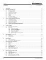
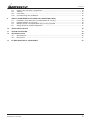
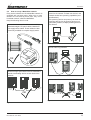
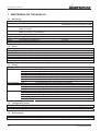
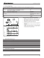
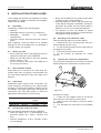
1
USERS MANUAL / GEBRUIKERSHANDLEIDING BETRIEBSANLEITUNG / MANUEL UTILISATEUR MANUAL DE UTILIZACION / INSTRUZIONI PER L’USO Mass GI 3.5 / 7.0 / 7.0 MultiTap Isolation transformer MASTERVOLT Snijdersbergweg 93, 1105 AN Amsterdam The Netherlands Tel.: +31-20-3422100 Fax.: +31-20-6971006 www.Mastervolt.com ENGLISH: NEDERLANDS: DEUTSCH: FRANÇAIS: CASTELLANO: ITALIANO: PAGE 1 PAGINA 25 SEITE 49 PAGINA 73 PÁGINA 97 PÁGINA 121 Copyright © 2009 Mastervolt, v 3.2 June 2009 OVERVIEW 1 OVERVIEW 4 3 100% uvp / ovp 75% 50% High temp 25% 5% Short circuit On 1 Stand by 2 On ISOLATION TRANSFORMER 16 1 2 3 4 5 6 6 5 Inside connection compartment: 7 AC input Line 8 AC input Neutral 9 Earth 10 Thermal fuse 20A-T 11 Fan 12 AC output Line 13 AC output Neutral 14 Protective Earth 15 MasterBus connectors 16 Identification labels (1 outside, 1 inside) 15 INPUT 7 L N OUTPUT L N 8 9 10 20AT Push to reset 11 2 12 13 Main switch LED On LEDs Load bar Failure LEDs Cable glands Grommet for MasterBus cabling 14 Figure 1: Overview Mass GI 3.5 June 2009 / Mass GI / EN OVERVIEW 18 17 19 20 17 Fans 18 MasterBus connectors 19 Input terminal Earth AC input Neutral AC input Line 20 Output terminal Protective Earth AC output Neutral AC output Line WARNING Never connect Earth (input) to Protective Earth (output)! Figure 2: Overview Mass GI 7.0/ 7.0 MultiTap EN / Mass GI / June 2009 3 CONTENTS CONTENTS v 3.2 June 2009 1 OVERVIEW 2 GENERAL INFORMATION 6 2.1 Product description ............................................................................................................................. 6 2.2 Use of this manual .............................................................................................................................. 6 2.3 Guarantee specifications .................................................................................................................... 6 2.4 Validity of this manual......................................................................................................................... 6 2.5 Quality................................................................................................................................................. 6 2.6 Liability ................................................................................................................................................ 6 2.7 Identification label ............................................................................................................................... 6 2.8 Changes to the Mass GI ..................................................................................................................... 6 3 SAFETY GUIDELINES AND MEASURES 7 3.1 Warnings and symbols ....................................................................................................................... 7 3.2 Use for intended purpose ................................................................................................................... 7 3.3 Organizational measures.................................................................................................................... 7 3.4 Maintenance & repair.......................................................................................................................... 7 3.5 General safety and installation precautions........................................................................................ 7 3.6 Warning regarding life support applications ....................................................................................... 7 4 HOW IT WORKS 8 4.1 MasterBus communication ................................................................................................................. 8 4.2 Protection............................................................................................................................................ 8 4.2.1 Overload protection ............................................................................................................... 8 4.2.2 Second overload protection................................................................................................... 8 4.2.3 Peak current limitation ........................................................................................................... 8 4.2.4 Short circuit protection........................................................................................................... 8 4.2.5 Thermal protection................................................................................................................. 8 4.2.6 MasterBus power supply protection ...................................................................................... 8 5 OPERATION 9 5.1 Resetting the Mass GI ........................................................................................................................ 9 5.2 Maintenance ....................................................................................................................................... 9 5.3 LED indicators .................................................................................................................................... 9 6 MASTERBUS 10 6.1 What is MasterBus?.......................................................................................................................... 10 6.2 How to set up a MasterBus network................................................................................................. 11 7 MASTERBUS ON THE MASS GI 12 7.1 Monitoring ......................................................................................................................................... 12 7.2 Alarm................................................................................................................................................. 12 7.3 History............................................................................................................................................... 12 7.4 Configuration general ....................................................................................................................... 12 7.5 Reset settings ................................................................................................................................... 12 7.6 Event Configuration .......................................................................................................................... 13 7.7 Mass GI Event Source List ............................................................................................................... 13 7.8 Mass GI Event Target List ................................................................................................................ 13 8 INSTALLATION STAND ALONE 14 8.1 Unpacking ......................................................................................................................................... 14 8.2 Before you start ................................................................................................................................ 14 8.3 Extra materials needed..................................................................................................................... 14 8.4 Cable sizes ....................................................................................................................................... 14 8.5 Choosing the location to install......................................................................................................... 14 8.6 Mounting of the cabinet to a wall ...................................................................................................... 14 4 June 2009 / Mass GI / EN 2 CONTENTS 8.7 8.8 8.9 8.10 Opening the connection compartment.............................................................................................. 14 Cabling.............................................................................................................................................. 15 Connection........................................................................................................................................ 15 Commissioning after installation....................................................................................................... 15 9 TWO TO FOUR MASS GI’S IN PARALLEL (ADDITIONAL INFO) 16 9.1 Installation of four Mass GI’s in parallel (Mass GI 3.5 only) ............................................................. 16 9.2 Parallel operation in one group......................................................................................................... 16 9.3 Multiple groups of (multple) Mass GI(s) running in parallel .............................................................. 16 9.4 Safety devices in parallel configuration ............................................................................................ 17 10 QUICK INSTALLATION 18 11 TROUBLE SHOOTING 19 12 TECHNICAL DATA 20 12.1 Specifications.................................................................................................................................... 20 12.2 Dimensions ....................................................................................................................................... 21 13 EC DECLARATION OF CONFORMITY EN / Mass GI / June 2009 23 5 GENERAL INFORMATION 2 GENERAL INFORMATION 2.1 Product description The Mass GI is an isolation transformer, based on switch mode technology, providing you with a separation between AC shore-power and the onboard AC electrical system. This prevents corrosion of your metal ship while grounding is still present. The input circuit of the Mass GI is equipped with a soft start circuit to eliminate high inrush currents, and an automatic circuit breaker (Mass GI 3.5) or internal fuse (Mass GI 7.0) to protect your system against electrical overload. 2.2 Use of this manual Copyright © 2009 Mastervolt. All rights reserved. Reproduction, transfer, distribution or storage of part or all of the contents in this document in any form without the prior written permission of Mastervolt is prohibited. This manual serves as a guideline for the safe and effective operation, maintenance, trouble shooting and configuration of the Mass GI. It is therefore obligatory that every person who works with the Mass GI is completely familiar with the contents of this manual, and that he/she carefully follows the instructions contained herein. Installation of, and work with the Mass GI, may be carried out only by qualified, authorised and trained personnel, consistent with the locally applicable standards and taking into consideration the safety guidelines and measures (chapter 3 of this manual). Keep this manual at a secure place! 2.3 Guarantee specifications Mastervolt guarantees that this unit has been built according to the legally applicable standards and specifications. Should work take place, which is not in accordance with the guidelines, instructions and specifications contained in this users manual, then damage may occur and/or the unit may not fulfil its specifications. All of these matters may mean that the guarantee becomes invalid. The guarantee is limited to the costs of repair and/or replacement of the product. Costs for installation labor or shipping of the defective parts are not covered by this guarantee. 2.4 Validity of this manual versions of the Mass GI delivered by Mastervolt, with part numbers: 88060705, 88000705 or 88000355. For other models see manuals available on www.mastervolt.com. 2.5 Quality During production and prior to delivery, all of our units are tested and inspected. The standard guarantee period is two years after date of purchase. 2.6 Liability Mastervolt can accept no liability for: • consequential damage due to Mass GI use; • possible errors in the manuals and the results thereof. 2.7 Identification label The identification label is located at the right-hand side of the Mass GI and in the connection compartment (see figure 1, 2). Important technical information required for service, maintenance & secondary delivery of parts can be derived from the identification label. Part no: 88000705 Type: Input: Isolation transformer Mass GI 100-240V AC 50-60Hz 3.2-7.0kW max 32A Output: 100-240V AC 50-60Hz Figure 3: Identification label CAUTION! Never remove the identification label. 2.8 Changes to the Mass GI Changes to the Mass GI may be carried out only after obtaining the written permission of Mastervolt. All of the specifications, provisions and instructions contained in this manual apply solely to standard 6 June 2009 / Mass GI / EN SAFETY GUIDELINES AND MEASURES 3 SAFETY GUIDELINES AND MEASURES WARNING! Before using the Mass GI, read and save these safety instructions. 3.1 Warnings and symbols Safety instructions and warnings are marked in this manual by the following pictograms: A procedure, circumstance, etc which deserves extra attention. CAUTION! Special data, restrictions and rules with regard to preventing damage. WARNING A WARNING refers to possible injury to the user or significant material damage to the GI if the user does not (carefully) follow the procedures. 3.2 Use for intended purpose 1 The Mass GI is constructed as per the applicable safety-technical guidelines. 2 Use the Mass GI only: • at the input connected to a dedicated double pole circuit breaker and earth leakage switch; • in a technical correct condition; • in a well-ventilated room, protected against rain, moist, dust and condensation; • observing the instructions in the users manual. WARNING Never use the Mass GI in situations where there is danger of gas or dust explosion or potentially flammable products! 3 Use of the Mass GI other than mentioned in point 2 is not considered to be consistent with the intended purpose. Mastervolt is not liable for any damage resulting from the above. 3.4 1 If the Mass GI is switched off during maintenance or repair activities, it should be secured against unexpected and unintentional switching on: • Remove the AC supply • Be sure that third parties cannot reverse the measures taken. 2 Use original spare parts only. 3.5 Organizational measures The user must always: • have access to this manual; • be familiar with the contents of this manual. This applies in particular to chapter 3. EN / Mass GI / June 2009 General safety and installation precautions • Install the Mass GI according to this manual. • Connections, wiring, grounding and other safety features must be executed according to the locally applicable regulations. • Use cables with an appropriate size. • Use the Mass GI in accordance with the specifications as stated in section 12.1. • Except for the connection compartment never open the housing as high voltages may be present inside! • When opening the connection compartment, disconnect the AC-input first. • Do not expose the Mass GI to rain, snow, spray, moisture, excessive pollution and condensing circumstances. To reduce risk of fire hazard, do not cover or obstruct the ventilation openings. Install the Mass GI in a well ventilated area to prevent overheating. • The Mass GI must be provided with an equipment-grounding to the AC-input ground terminal. • Check the wiring and connections at least once a year. Defects such as loose connections, burned cables etc. must be corrected immediately. • Do not touch the equipment when wet or if your hands are clammy. • Only allow changes in your electrical system to be carried out by qualified electricians. • In case of fire, use a fire extinguisher for electrical equipment. 3.6 3.3 Maintenance & repair Warning regarding applications life support The Mass GI products are not sold for applications in any medical equipment intended for use as a component of any life support system unless a specific written agreement pertaining to such intended use is executed between the manufacturer and Mastervolt. 7 HOW IT WORKS 4 HOW IT WORKS In order to prevent electrical corrosion of metal parts on your ship while maintaining the onboard earth, a separation between the AC shore power and the onboard AC power is necessary. As mentioned before, the Mass Isolating Transformer provides you with this separation. It is installed in between the AC shore power connection and the onboard AC loads. If 3.5 kW of shore power is not sufficient, more Mass GI’s can be connected in parallel to increase the power up to 14 kW maximum. With the Mass GI’s in parallel, power conversion will be divided between the units. See chapter 9 for more details. 4.1 MasterBus communication The Mass GI communicates via the MasterBus network. This network is used for remote control and remote (alarm) monitoring of the Mass GI, for configuration (in parallel) and for communication with other system devices. See chapters 6 and 7 for more information. 4.2 Protection The Mass GI is protected against overload, peak current, short circuit and high temperature. See section 5.1 for LED indications when a protection comes into effect. 4.2.1 Overload protection The Mass GI is equipped with an integrated fuse which limits the input current to 16A. This fuse will switch the Mass GI to Stand by in overload situations and trigger the MasterBus alarm. 5. Wait for at least two minutes and then reset the 20AT fuse by pushing the button inside the connection compartment, see figure 1 ref.10. 6. Close the connection compartment again. 7. Connect the Mass GI to the power sources. 8. Switch on the Mass GI. If the fuse trips again in short time, please contact your Mastervolt supplier for service. At the Mass GI 7.0 (MultiTap) the 20AT fuse is located inside the device. Therefore corrections can only be performed by qualified technicians. 4.2.3 Peak current limitation The Mass GI is automatically protected against a peak current during a short period. 4.2.4 Short circuit protection The Mass GI is protected against a short circuit situation by a fuse which trips when during 1 second short circuit conditions are met. In case of short circuit, the Mass GI switches to Standby, the short circuit LED illuminates and the MasterBus alarm is triggered. 4.2.5 Thermal protection The Mass GI is protected against high temperature by 3 integrated thermal fuses. If one of these fuses trips, the Mass GI will switch to Stand by, the high temperature LED illuminates and the MasterBus alarm is triggered. 4.2.6 MasterBus power supply protection The MasterBus power supply (internal aux power supply) is protected by means of a 1A fuse. 4.2.2 Second overload protection The Mass GI is protected by a 20AT fuse as well. This fuse switches off the Mass GI input, there will be no MasterBus alarm. To correct the situation at the Mass GI 3.5, proceed as follows: 1. Move the main switch of the Mass GI to the Standby position. 2. Disconnect the Mass GI from any power source. Disconnect all loads from the Mass GI. 3. Investigate the cause of failure of the thermal fuse like overload or short-circuits. 4. Refer to section 8.7 to open the connection compartment. 8 June 2009 / Mass GI / EN OPERATION 5 OPERATION The Mass GI can be activated by switching the main switch (figure 1, ref. 1) to the “ON” position. When no error is present, the green ON LED illuminates after this. The Mass GI will then generate an AC output voltage. Move the switch to the Standby position to switch off the Mass GI. In standby the Mass GI remains connected to the AC mains! 5.1 Maintenance No specific maintenance is required. If necessary, use a soft clean cloth to clean the Mass GI. Never use any liquids, acids and/or scourers. For reliable and optimum function examine your electrical installation on a regular base, at least once a year. Defects such as loose connections, burnt wiring etc. must be corrected immediately. Resetting the Mass GI When the Mass GI is in failure mode it can be reset in two ways: 1. By switching it Off and On again using the main switch (figure 1 ref. 1). 2. By using the MasterBus function Restart (section 7.1). f 100% e 75% d 50% c uvp / ovp High temp g h 25% b 5% Short circuit i on stand by a 5.2 5.3 LED indicators The operation of the Mass GI is displayed by means of front panel LEDs. See the table below for explanation. Illuminating LED a a (blinking) a+b a+b+c a+b+c+d a+b+c+d+e a+b+c+d+e +f (yellow) a+b+c+d+e +f (red) f (red) g Status On Waiting Normal Normal Normal Normal Normal Meaning Mass GI is switched on. Mass GI waits for parallel units to switch on. Current conversion: 5% of nominal current. Current conversion: 25% of nominal current. Current conversion: 50% of nominal current. Current conversion: 75% of nominal current. Current conversion: 100% of nominal current. Overload Current conversion: >100% of nominal current, Mass GI will be shut off soon due to overload. Mass GI has been shut off due to overload. Mass GI has been shut off due to too low or too high input voltage. Mass GI has been shut off due to a frequency error on the input. Mass GI has been shut off due to too high temperature. Mass GI has been shut off due to short circuit. Failure mode Failure mode g (blinking) Failure mode h Failure mode i Failure mode On ISOLATION TRANSFORMER Table: Front LEDs with function EN / Mass GI / June 2009 9 MASTERBUS 6 MASTERBUS All devices that are suitable for MasterBus are marked by the MasterBus symbol. which show full status information of your electrical system at a glance and a push of a button. All monitoring panels can be used for monitoring, control and configuration of all connected MasterBus devices. MasterBus is a fully decentralized data network for communication between the different Mastervolt system devices. It is a CAN-bus based communication network which has proven a reliable bus-system in automotive applications. MasterBus is used as power management system for all connected devices, such as the inverter, battery charger, generator and many more. This enables communication between the connected devices, for instance to start the generator when the batteries are low. New devices can be added to the existing network in a very easy way by just extending the network. With this the MasterBus network offers a high degree of flexibility for extended system configuration, not only today, but in the future as well! Mastervolt also offers several interfaces, making even non-MasterBus devices suitable to operate in the MasterBus network. For direct communication between the MasterBus network and a product which is not from Mastervolt, the Modbus interface is recommended. MasterBus reduces complexity of electrical systems by using UTP patch cables. All system components are simply chained together. The results are a reduction of material costs as only a few electrical cables are needed and less installation time. CAUTION: Never connect a nonMasterBus device to the MasterBus network directly! This will void warranty of all MasterBus devices connected. 6.1 What is MasterBus? For central monitoring and control of the connected devices Mastervolt offers a wide range of panels 10 The event configuration of the Mass GI as target and as source is described in chapter 7 of this manual. June 2009 / Mass GI / EN MASTERBUS 6.2 How to set up a MasterBus network Every device suitable for the MasterBus network is equipped with two data ports. When two or more devices are connected by these ports, they form a local data network, called the MasterBus. Keep the following rules in mind: Connections between the devices are made by standard straight UTP patch cables. Mastervolt can supply these cables. These cables are also commonly available at computer supply stores. The connected devices provide the electric power for the network. At least one device in the network should have powering capabilities (see specifications). One powering device can power up to three nonpowering devices. As all powering devices are galvanically isolated, multiple powering devices are allowed. OK 1-8 Figure 6 Do not make ring networks OK Figure 4 As with all high speed data networks, MasterBus needs a terminating device on both ends of the network. Figure 7 Do not make T-connections in the network. Terminating device Terminating device OK Figure 8 Figure 5 EN / Mass GI / June 2009 11 MASTERBUS ON THE MASS GI 7 MASTERBUS ON THE MASS GI 7.1 Monitoring Variable State Description Mass GI status Default - Shore fuse Set maximum shore fuse current (Mass GI 3.5 kW) Set maximum shore fuse current (Mass GI 7.0 kW/ 7.0 kW Multitap) Switching function (no front switch override) Voltage at input of the GI Current at input of the Mass GI Input power of the Mass GI Input frequency 16A Range OK,Standby,No shore,Waiting,Load high, Overload,Short circuit,Configuration fault 2A, 4A, 6A, 10A, 14A, 16A, Unlimited 32A 4A, 8A, 12A, 20A, 28A, 32A, Unlimited - 0-300 V 0-16 A 0-5.0 kW 35-70 Hz Shore fuse Restart Input voltage Input current Power Frequency 7.2 Alarm Variable Voltage high Voltage low Temperature high Short circuit Overload Frequency fail 7.3 History Category AC present AC not present Total Latest alarms 7.4 Description Period shore power has been present since latest shore power connection. Energy consumed since latest connection to shore power. Maximum input current since latest connection to shore power. Average input current during latest connection to shore power. Maximum input voltage since latest connection to shore power. Average input voltage during latest connection to shore power. Minimum input voltage since latest connection to shore power. Time elapsed when no shore power was available. Total operating time since first use of the Mass GI. Total energy consumed since first use of the Mass GI. Average total input current since first use of the Mass GI. Select an alarm to see the values of (maximum 9 alarms can be stored). Shows the present alarm if applicable. Input voltage at detection of the alarm shown. Output voltage at detection of the alarm shown. Output current at detection of the alarm shown. Description Set the Mass GI menu language. Any name with 12 characters max. Default English Mass GI Range See specifications Max 12 characters Reset settings Variable Reset settings 12 Variable Time Energy Max A Average A Max V Average V Min V Time Runtime Energy Average A Latest Alarm Input voltage Output voltage Output current Configuration general Variable Language Device name 7.5 Description Input voltage over 253V. Input voltage under 90V. The internal temperature is higher than 90°C/194°F, the Mass GI is in Failure mode. A too high current has been measured during a predetermined period of time. The load on the output is too high. The input frequency is out of range: below 45Hz or over 65Hz. Description This option allows resetting the Mass GI to default (factory) settings. June 2009 / Mass GI / EN MASTERBUS ON THE MASS GI 7.6 Event Configuration In Event configuration, changing variables of the Mass GI can be used to trigger other devices. Variable Description Default Range Event x Event by the Mass GI that should result in an action by Disabled See section 7.7 Event source source one of the other devices on the MasterBus network. list Nine events are available: x can be 1-9 Event x Select a connected MasterBus device that should take Select… Selectable targets are system target action due to a Mass GI event. dependent. Event x Action to be taken by the target device. Select… See command list in manual of command the selected device. Mass GI section 7.8. Event x Data is linked to the command. See also figure 9. Off Off, On, Copy, Copy Invert, data Toggle. Figure 9 shows the meaning of the event data. • Input is a pulse followed by a longer signal (1/0). • On changes the status to On at the first signal. • Off changes the status to Off at the first signal. • Copy lets the status follow the input. • • Copy Invert lets the status follow the opposite of the input. • Toggle changes the status at the first signal and back at the second signal. It is often used in combination with a pulse switch. Input Output On Off Copy Copy Invert Toggle Figure 9: Event data 7.7 Mass GI Event Source List Variable Load 5% Load 25% Load 50% Load 75% Load 100% Pre overload Fan on Failure mode 7.8 Description Mass GI load is 5% of maximum. Mass GI load is 25% of maximum. Mass GI load is 50% of maximum. Mass GI load is 75% of maximum. Mass GI load is 100% of maximum. Mass GI is going to be in overload if the actual situation lasts. The internal fan is switched on. Mass GI is in failure mode Mass GI Event Target List Variable Restart EN / Mass GI / June 2009 Description Restart the Mass GI Range 13 INSTALLATION STAND ALONE 8 INSTALLATION STAND ALONE In this chapter we describe the installation of a stand alone Mass GI. Chapter 9 describes the installation of Mass GI’s in parallel. 8.1 Unpacking The delivery consists of the following parts: • Mass GI • MasterBus cable (in connection compartment) • MasterBus terminator (in connection compartment) • This user’s manual. Save this manual at a secure place! After unpacking, check the Mass GI for possible damage. Do not use the Mass GI if it is damaged. If in doubt, contact your supplier. 8.2 Before you start • Be sure that the output of the supplying source is switched off during the entire installation. • Make sure the main switch is set to the Standby position. See fig 1, ref 1. • Do not connect the AC-output of the Mass GI to an incoming AC source. 8.3 • Never use the Mass GI at a location where there is danger of gas or dust explosions. • Mount the Mass GI in such a way that obstruction of the airflow through the ventilation openings is prevented. No objects must be located within a distance of 10 cm / 4 inch around the Mass GI. • For optimum air flow, the MASS GI should always be mounted vertically, this means with the cable glands facing downwards. 8.6 Mounting of the cabinet to a wall Take the following steps to mount the cabinet: 1. Determine the four mounting spots using the outline drawings (section 12.2). 2. Fix the mounting screws into the surface but do not tighten them entirely. 3. Place the housing over the screws. 4. Fix the housing by fastening the screws securely. 8.7 Opening the connection compartment The connection compartment must never be opened while the Mass GI is connected to a power source. 1 Extra materials needed Every Mass GI is mounted to the wall using four screws (with rings and plugs), recommended size m8. Use suiting materials to carry the weight of the Mass GI. 8.4 Cable sizes Undersized cables and/or loose connections can cause dangerous overheating of the cables and/or terminals. In order to limit transition resistance as far as possible, use proper cable sizes and tighten all connections well. See table below to select the appropriate cross section for the AC wiring: Model AC Current Mass GI 3.5 Mass GI 7.0 0-16 A 16-35 A 8.5 Step 1 2x Min. cross section 2.5 mm² 6.0 mm² AWG 13 8 Choosing the location to install Step 2 5 AWG Figure 10 See figure 10. Steps: 1. Loosen the two Phillips screws A and B that secure the front cover plate (1) for two turns. 2. Slide the front cover plate (1) from the cabinet (downwards). 3. The terminals and fuse button are accessible now. Obey the following stipulations during installation: • Install the Mass GI in a well-ventilated room protected against rain, vapour, moisture and dust. • Ambient temperature: 0-40°C, Humidity: 0-90% non condensing. 14 June 2009 / Mass GI / EN INSTALLATION STAND ALONE 8.8 WARNING Never connect Earth (input) to Protective Earth (output)! Cabling The wiring is connected inside the connection compartment. If necessary, the cabling can be fed from the top to the bottom side of the cabinet along the back of the cabinet. Always feed the wiring through the cable glands (fig.1 ref. 5) of the cabinet, and then connect the wiring to the terminals. Cut the wiring as shown in figure 11. Strip the conductors for 8 mm. The diameter of the outer isolation must be between 10 and 14 mm to fit in the cable glands correctly enabling strain relieve. For safe installation it is necessary to: • Connect both the earth (PE/GND) and the neutral (N) of the AC output of the Mass GI to the grounding point, fig. 16. This grounding point must be connected to the central ground connection of the ship, which is connected to the hull of the ship. • Integrate a Residual Current Device (RCD) in wiring of the AC output. Refer to local applicable regulations on these issues. 8.9 5 cm at least PE/GND green/yellow L/Phase brown N/neutral blue Europe 230V AC Single phase system 5 cm at least L/Phase black PE/GND green N/neutral white Connection Steps: 1. Connect the AC load to the AC output (fig.16). 2. Connect the incoming shore power via a circuit breaker to the AC input (fig.15). Phase line to L, Neutral to N, and Ground to PE/GND. 8.10 Commissioning after installation 1. Tighten all cable glands (fig. 1, ref. 5) to ensure the strain relief. 2. Check all wiring and connections. 3. Close the front cover plate of the connection compartment. Beware that the cabling does not obstruct the cooling fan (fig. 1, ref.11) and air flow. Now the Mass GI is ready for operation! USA 120 V AC Single phase system 5 cm at least L1/Phase black PE/GND green L2/Phase red USA 240 V AC Double phase system Figure 11: Wiring EN / Mass GI / June 2009 15 TWO TO FOUR MASS GI’S IN PARALLEL (ADDITIONAL INFO) 9 TWO TO FOUR MASS GI’S IN PARALLEL (ADDITIONAL INFO) For shore connections of more than 16A (32A), multiple Mass GIs can be used in parallel (maximum four Mass GI 3.5 or two Mass GI 7.0/ Mass GI 7.0 MultiTap). 3. Connect the incoming shore power to the AC input on your Mass GI’s. Phase line to L, Neutral to N, and Ground to PE (figure 17). 9.1 CAUTION! In parallel, all inputs must be connected to the same phase! Installation of four Mass GI’s in parallel (Mass GI 3.5 only) WARNING! Never connect the output(s) to any other power source! Extra materials needed for 4 Mass GI’s: 16 screws (with rings and plugs), size m8. Use suiting materials to carry the weight of the Mass GI. If you have more than four Mass GI’s to put in parallel, you need to install two groups, using manual setup. See figure 12 for installation. Steps: 1. Connect the MasterBus cable between the communication ports on the Mass GI’s. 2. Connect the AC load to the AC output on the units (figure 16). To achieve maximum performance all input and output wiring must be of equal length. For more than two Mass GI’s we recommend a star configuration like shown in figure 12. Input 2.5 mm2 Output 2.5 mm2 MasterBus Input from shore power 10 mm2 Output to loads 10 mm2 Mass GI 14 MV Easy On On MASTERVOLT Figure 12: Parallel connection of four Mass GI 3.5 in one group 9.2 Parallel operation in one group In one group all Mass GIs in the MasterBus network run in parallel. Parallel configuration is done automatically via MasterBus communication. When two, three or four units are detected in a MasterBus network, the system assumes that these operate in parallel. 9.3 Multiple groups of Mass GI(s) in parallel With more than four Mass GI’s in parallel you need more than one group. For example 8 Mass GI’s can be configured as two groups of four Mass GIs running in parallel. In this situation additional configuration of the system is required. Per group of GI’s one of the units needs to be assigned the status of Master. In “Configuration” > “Parallel” one should 16 select “Master”. After this action the required number of Mass GIs can be selected to run in parallel to the Master via selection in Product 1, Product 2, Product 3 and Product 4. Note Product 1 is the product that was selected as Master. Rename Mass GIs before configuring multiple groups of GIs. For example “Transformer 1” etc. If the automatic paralleling of Mass GI’s is not desirable, select “Master” on the units in parallel configuration and do not select additional products to run in parallel. This effectively creates single units that will not switch to parallel mode automatically. June 2009 / Mass GI / EN TWO TO FOUR MASS GI’S IN PARALLEL (ADDITIONAL INFO) 9.4 Safety devices in parallel configuration The figure below shows the recommended safety devices and their rates for parallel configuration. At the input only one circuit breaker is sufficient, given the fuse is rated according to the total input current. At the output, each Mass GI shall be provided with a circuit breaker and the common output must contain a residual current device suitable for the total output current. = Input = Output Thermal Magnetic = MasterBus 32A 1 Mass GI 3.5: 16 A 2 Mass GI 3.5: 32 A 3 Mass GI 3.5: 50 A 4 Mass GI 3.5: 63 A 32A 1 Mass GI 7.0: 32 A 2 Mass GI 7.0: 63 A Figure 13: Safety devices with paralleled Mass GI. EN / Mass GI / June 2009 17 QUICK INSTALLATION 10 QUICK INSTALLATION 1 This section provides a brief overview of a basic stand alone installation of the Mass GI. However; please review the entire manual for connection of additional features and to ensure best performance and years of trouble-free service. 2 The electrical system must be disconnected from any power source during the entire installation! 3 Mount the Mass GI to a vertical surface. Allow at least 10 cm / 4 inch space around the apparatus! 5 Connect the AC load to the Mass GI AC output. We recommend to connect both the AC output earth (PE) and the neutral (N) to the central grounding point which is connected to the hull of the ship, using a Residual Current Device (RCD) in the wiring of the AC output. Refer to local applicable regulations. RCD Mass GI 3.5 Mass GI 7.0/ 7.0 MultiTap RCD Figure 16 6 Use M8 or M10 screws. Figure 14 4 Open the connection compartment: • Loosen the two Philips screws that secure the front cover plate for two turns. • Slide the front cover plate from the cabinet. Step 1 2x Step 2 Figure 15 Connect the contra plug for incoming shore power via an external circuit breaker to the AC input terminal of the Mass GI. Phase line to L, Neutral to N, Ground to PE. Do NOT connect the ground wire (PE) of the shore power to the central grounding point (hull of the ship), neither to the PE connection of the output or to the Mass GI enclosure! Circuit breaker Figure 17 7 Close the connection compartment. Connect shore power to the Mass GI. Switch On the Mass GI. Check LED “On” and ensure that failure LEDs are Off. In case of failure, disconnect shore power and check Mass GI. Figure 18 18 June 2009 / Mass GI / EN TROUBLE SHOOTING 11 TROUBLE SHOOTING See section 5.3 for LED indicators. Problem Possible cause No output power, all LED Main switch is in position indicators are off. STAND BY. No shore power available on AC input. 20AT fuse has tripped. No output power, only the External RCD has tripped. On LED (figure 1, ref. 2) illuminates. No output power, Input voltage is/ was OVP/UVP LED is on. either too high or too low. No output power, OVP/UVP LED is blinking. No output power, High temp LED is on. Input frequency is/ was either too high or too low. Environmental temperature is too high. Fan is blocked. Too much load connected. No output power, Short circuit LED is on. Short circuit at the output. No output power, “100%” LED illuminates red. MasterView Easy panel connected to the GI, no communication. Parallel units are shut off due to overload while load is less than 3.5 (7.0) kW per unit. No MasterView display function. Overload. Slow or no MasterBus communication. Error in the MasterBus wiring. No terminating device placed at the ends of the network. MasterBus network is configured as a ring network. EN / Mass GI / June 2009 The Easy panel has been switched off or MasterBus is not working correctly. Installation fault. Display is switched off. Error in the wiring. No powering device available on the MasterBus. What to do? Switch ON the Mass GI. See chapter 5. Check the circuit breaker of the shore power (on the quay). Check the wiring of the shore power cable. Reset the fuse (see section 4.2.2). Mass GI is working normally. Check the external RCD at the AC output (if applied). Check the input voltage. Then reset the Mass GI by switching it Standby, On or by using Restart (MasterBus). Check the input frequency. Then reset the Mass GI (see section 5.2). Check temperature. Reduce load and let the Mass GI cool down. Then reset the GI (see section 5.2). Make sure the fan is not blocked by the wiring of the connection compartment. See section 8.7 to open the connection compartment. Reduce the connected load. Then reset the Mass GI (see section 5.2). Use an extra GI in parallel. Remove the short circuit. Then reset the Mass GI (see section 5.2). Reduce the connected load. Then reset the Mass GI (see section 5.2). Check MasterBus wiring, a terminator should be placed on both ends of the MasterBus network. Cable lengths and thickness must be of the same size for all units. See chapter 9. Switch on display, refer to display manual. Check the MasterBus cables. With shore power disconnected the Mass GI does not power the MasterBus network. At least one other connected MasterBus device should have powering capabilities. Check the MasterBus cables. MasterBus needs a terminating device on both ends of the network. Check if connected (see section 6.2). Ring networks are not allowed. Check the connections of the network (see section 6.2). 19 TECHNICAL DATA 12 TECHNICAL DATA 12.1 Specifications Model Article number: Nominal power: MASS GI 3.5 88000355 3500VA @ 230V MASS GI 7.0 88000705 7000VA @ 230V MASS GI 7.0 MultiTap 88060705 7000VA @ 230V/ 3500VA @ 120V Input Input voltage: 90-255V 90-255V 45..65Hz 16A cont 60 W rms 45..65Hz 32A cont 60 W rms 90-145VAC or 180255VAC 45..65Hz 32A cont 60 W rms 600 mA rms/ 11W 600 mA rms/ 11W 600 mA rms/ 11W 10mA 10mA 10mA Input frequency: Nominal input current: No load AC current consumption: Standby AC current consumption: DC current consumption, no MasterBus traffic: Earth leakage protection: Output Output voltage: Output frequency: Output current behavior: Efficiency (max): MasterBus powering capability Options Remote panel: Parallel operation: Environment Dimensions L x W x H: Not present inside, an external RCD is required Same as input voltage ± 5% Same as input frequency Fuse B characteristic >93% Yes, if shore power is present Same as input voltage ± 5% Same as input frequency Fuse B characteristic >93% Yes, if shore power is present Same as input frequency Fuse B characteristic >93% Yes, if shore power is present Optional, MasterView panel. Yes, up to four units can be paralleled. Optional, MasterView panel. Yes, up to two units can be paralleled. Optional, MasterView panel. Yes, up to two units can be paralleled. 371x261x145 mm / 371x261x232 mm / 371x261x232 mm / 14.6x10.3x5.7 inch 14.6x10.3x9.1 inch 14.6x10.3x9.1 inch 5.6 kg (12 lbs) 10 kg (22 lbs) 10 kg (22 lbs) Full specifications from 0°C/32°F to 40°C/104°F. Derating: 5%/°C (3%/°F) at ambient temperatures from 40°/104°F to 60°C/140°F. Shutdown at 90°C/194°F heat sink temperature. -20°C/-4°F to 60°C/104°F -20°C/-4°F to 60°C/104°F -20°C/-4°F to 60°C/104°F Approximate weight: Specified operation temperature: (will meet specified tolerances) Allowed operating temperature: (may not meet specified tolerances) Non operating Ambient temperature Ambient temperature temperature: (storage 40°C/-40°F to 40°C/-40°F to temperature) 100°C/212°F 100°C/212°F Relative humidity: Max 95% relative humidity, non condensing. Environment class: IP 21 IP 21 NOTE: specifications are subject to change without prior notice. 20 230V ± 5% Ambient temperature 40°C/-40°F to 100°C/212°F IP 21 June 2009 / Mass GI / EN TECHNICAL DATA 12.2 Dimensions 0,47 237 9,33 145 5,69 12 0,47 332 13,07 19 0,75 113 4,43 31 1,22 34 1,34 279 371 10,96 14,60 20 0,77 12 Figure 19: Dimensions in mm [inch] of Mass GI 3.5 EN / Mass GI / June 2009 21 TECHNICAL DATA Figure 20: Dimensions in mm [inch] of Mass GI 7.0 and Mass GI 7.0 MultiTap 22 June 2009 / Mass GI / EN EC DECLARATION OF CONFORMITY 13 EC DECLARATION OF CONFORMITY Manufacturer: Address: Mastervolt Snijdersbergweg 93 1105 AN Amsterdam The Netherlands Herewith declares that: Product: 88000355 88000705 88060705 Mass GI 3.5 Mass GI 7.0 Mass GI 7.0 MultiTap Is in conformity with the Low Voltage Directive 2006 / 95 / EC With standards: Recreational Craft Directive 94 / 25 / EEG With standard: EN 60950-1 : 2001 EN 61558-1 : 2005 EN 61558-2-4 : 1997 NEN-ISO 13297 : 2000 Electromagnetic Compatibility Directive 2004 / 108 / EC With standards: EN 61000-6-1 : 2007 EN 61000-6-2 : 2007 EN 61000-6-3 : 2007 EN 61000-6-4 : 2007 Amsterdam, P.F. Kenninck, C.E.O. MASTERVOLT EN / Mass GI / June 2009 23 Snijdersbergweg 93, 1105 AN Amsterdam, The Netherlands Tel : + 31-20-3422100 Fax : + 31-20-6971006 Email : [email protected]