1
Intelligent
Monitoring
Software
User Guide
Software Version 3.0 and above
RealShot Manager
© 2005 Sony Corporation
Copyright Notice
Copyright Notice
©2005 Sony Corporation. All rights reserved. This manual may not be reproduced, translated or
reduced to any machine readable form in whole or in part, without prior written approval from Sony
Corporation.
SONY CORPORATION PROVIDES NO WARRANTY WITH REGARD TO THIS MANUAL OR
INFORMATION CONTAINED HEREIN AND HEREBY EXPRESSLY DISCLAIMS ANY IMPLIED
WARRANTIES OF MERCHANTABILITY OR FITNESS FOR ANY PARTICULAR PURPOSE WITH
REGARD TO THIS MANUAL OR SUCH INFORMATION. IN NO EVENT SHALL SONY
CORPORATION BE LIABLE FOR ANY INCIDENTAL, CONSEQUENTIAL OR SPECIAL
DAMAGES, WHETHER BASED ON TORT, CONTRACT, OR OTHERWISE, ARISING OUT OF
OR IN CONNECTION WITH THIS MANUAL OR INFORMATION CONTAINED HEREIN OR THE
USE THEREOF.
Sony Corporation reserves the right to make any modification to this manual or the information contained
herein at any time without notice.
Trademarks
Microsoft, Windows and Windows NT are registered trademarks of Microsoft Corporation.
Intel and Pentium are registered trademarks of Intel Corporation.
Ethernet is a registered trademark of Xerox Corporation
All other brands and product names are trademarks or registered trademarks of their respective owners.
2
Table of Contents - Introduction
Table of Contents
Manual Overview .................................................................................................................5
TU
UT
Typographical Conventions ........................................................................................................... 5
TU
UT
Getting Started.....................................................................................................................6
Introduction ..........................................................................................................................6
RealShot Manager Basics ...................................................................................................7
RealShot Manager Prerequisites .........................................................................................7
TU
UT
TU
UT
TU
UT
TU
UT
PC Requirements .......................................................................................................................... 7
TU
UT
Software Installation ............................................................................................................8
TU
UT
Sony RealShot Manager Client ..................................................................................................... 8
Sony RealShot Manager Server .................................................................................................. 11
TU
UT
TU
UT
Troubleshooting the Client Installation ...............................................................................12
TU
UT
‘ODBC not set up during Initial Software Configuration’ .............................................................. 12
License Error ............................................................................................................................... 14
TU
UT
TU
UT
End User License Agreement ............................................................................................16
User Guide.........................................................................................................................19
Launching the Application ..................................................................................................19
TU
UT
TU
UT
TU
UT
Creating a Desktop Shortcut........................................................................................................ 20
Dealing with Licensing Issues...................................................................................................... 20
Contacting Sony .......................................................................................................................... 21
TU
UT
TU
UT
TU
UT
Navigating the User Interface ............................................................................................21
TU
UT
Resizing and Minimizing/Maximizing Windows ........................................................................... 21
Logging in to RealShot Manager ................................................................................................. 24
Using the Menus .......................................................................................................................... 24
Using the Toolbars....................................................................................................................... 25
Understanding the Status Bar...................................................................................................... 33
TU
UT
TU
UT
TU
UT
TU
UT
TU
UT
Monitoring ..........................................................................................................................34
TU
UT
Monitor Window Objects .............................................................................................................. 34
Creating a Monitoring Layout....................................................................................................... 35
Selecting a Monitoring Layout ..................................................................................................... 35
Selecting Display Items ............................................................................................................... 35
Freezing the Monitored Image ..................................................................................................... 37
Updating the Frame Rate ............................................................................................................ 37
Saving the Monitored Image ........................................................................................................ 38
Loading a saved image................................................................................................................ 38
Changing Cameras in the Monitoring Layout .............................................................................. 39
TU
UT
TU
UT
TU
UT
TU
UT
TU
UT
TU
UT
TU
UT
TU
UT
TU
UT
Controlling Cameras ..........................................................................................................43
TU
UT
Recording .................................................................................................................................... 48
Recording During Monitoring ....................................................................................................... 48
Scheduling Recordings ................................................................................................................ 49
TU
UT
TU
UT
TU
UT
Playback ............................................................................................................................64
TU
UT
Searching for Recordings ............................................................................................................ 64
Modifying the Search Window ..................................................................................................... 69
Browsing for Files ........................................................................................................................ 71
Cleaning Up Recordings .............................................................................................................. 71
Managing Archived Recordings ................................................................................................... 72
Previewing a Recording ............................................................................................................... 73
Exporting to an AVI File ............................................................................................................... 77
Monitoring Audio .......................................................................................................................... 79
Monitoring Alarms ........................................................................................................................ 80
TU
UT
TU
UT
TU
UT
TU
UT
TU
UT
TU
UT
TU
TU
UT
UT
TU
UT
Administrator Guide ...........................................................................................................81
TU
UT
3
Table of Contents - Introduction
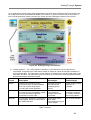
Configuring RealShot Manager..........................................................................................81
TU
UT
Types of Configuration................................................................................................................. 81
TU
UT
Scaling/Tuning a System ...................................................................................................82
Installing RealShot Manager Server ..................................................................................84
TU
UT
TU
UT
Linux Server................................................................................................................................. 84
Interfacing to an Archive .............................................................................................................. 87
TU
UT
TU
UT
General Settings ................................................................................................................91
TU
UT
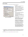
User Interface Settings (General Tab) ......................................................................................... 91
Modifying and Sharing Directories ............................................................................................... 93
Logging and Alarm Notification .................................................................................................... 94
Alarm Settings ............................................................................................................................. 95
User Log Settings ........................................................................................................................ 96
Joystick Settings .......................................................................................................................... 96
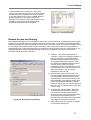
Remote Access and Sharing ....................................................................................................... 97
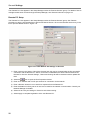
External Module Integration ......................................................................................................... 99
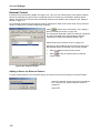
External Control ......................................................................................................................... 100
Layout Settings .......................................................................................................................... 102
External Application Integration ................................................................................................. 102
TU
UT
TU
UT
TU
UT
TU
UT
TU
UT
TU
UT
TU
UT
TU
UT
TU
UT
TU
UT
TU
UT
User Accounts .................................................................................................................105
TU
UT
Setting Permissions ................................................................................................................... 105
Adding/Removing Users ............................................................................................................ 107
Modifying User Details ............................................................................................................... 108
Managing User Groups.............................................................................................................. 109
Logging Off or Changing Accounts ............................................................................................ 110
TU
UT
TU
UT
TU
UT
TU
UT
TU
UT
Setup Manager ................................................................................................................111
TU
UT
Managing Devices ..................................................................................................................... 112
Understanding the Device/Group List ........................................................................................ 112
Managing Cameras ................................................................................................................... 115
Managing Storage Locations ..................................................................................................... 134
Managing Groups ...................................................................................................................... 138
Managing I/O Boxes .................................................................................................................. 141
Managing Audio Devices ........................................................................................................... 147
Importing and Exporting Device Configurations ........................................................................ 153
TU
UT
TU
UT
TU
UT
TU
UT
TU
UT
TU
UT
TU
UT
TU
UT
The Action Editor .............................................................................................................153
TU
UT
Editing Rules.............................................................................................................................. 154
Defining the Actions for a Rule .................................................................................................. 156
TU
UT
TU
UT
Housekeeping ..................................................................................................................160
TU
UT
Database Operations ................................................................................................................. 160
TU
UT
Layout Editor....................................................................................................................160
TU
UT
Layout Editor Tools .................................................................................................................... 160
Enabling the Layout Editor Toolbar ........................................................................................... 161
Creating a New Layout .............................................................................................................. 162
Selecting Layouts for Monitoring ............................................................................................... 170
Sharing Layouts ......................................................................................................................... 171
Planning a Monitor Layout ......................................................................................................... 173
TU
UT
TU
UT
TU
UT
TU
UT
TU
UT
TU
UT
Troubleshooting ...............................................................................................................185
TU
UT
Logging ...................................................................................................................................... 185
User Log Window ...................................................................................................................... 187
TU
UT
TU
UT
Error Messages ...............................................................................................................188
FAQ
...........................................................................................................................193
Glossary...........................................................................................................................194
Index
...........................................................................................................................197
TU
UT
TU
UT
TU
UT
TU
UT
4
Manual Overview - Introduction
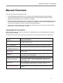
Manual Overview
This manual contains three individual guides:
•
The Getting Started guide will help you to install the Sony RealShot Manager software package.
•
The User Guide describes how to use RealShot Manager, it assumes that the software has been
installed and configured for the IP cameras in your system.
•
The Administrator Guide describes how to configure the cameras in your system and manage the users.
Many of the features described within this guide are only available to users with Administrator rights, if
you cannot use a feature you require. See your System Administrator.
•
The maximum number of frames per second for the image stream from a camera is written as 25 fps
based on PAL. In the case of NTSC, it is 30fps.
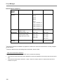
Typographical Conventions
Before you start using this manual, it is important to understand the terms and typographical conventions
used in the documentation.
The details of the various text formats that are used within this document are shown in the table below:
Format
Type of Information
Step 1.
Step-by-step procedures. You must follow these instructions to
complete a specific task.
1) Numbered List
•
Bulleted List (level 1)
°
Bulleted List (level 2)
A list of points referenced by numbers, often referring to a figure.
A list of points or values where the order is unimportant.
Special Bold
Items you must select such as menu options, command buttons or
items in a list.
Emphasis
Used to emphasise the importance of a point or for variable
expressions such as parameters.
T
T
T
T
CAPITALS
Names of keys on the keyboard, e.g. SHIFT, CTRL, ALT.
<Generic Description>
Text in angle brackets is a generic description of the item to be
substituted: <colour> could be replaced by any actual colour, e.g.
black, green, blue.
KEY + KEY
Future Developments
T
T
Key combinations for which the user must press and hold down
one key and then press another, e.g. CTRL+P, ALT+F4.
Features that are not yet implemented but are planned for a future
release.
5
Getting Started - Introduction
Getting Started
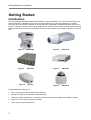
Introduction
The Sony RealShot Manager management software for video monitoring over a TCP/IP local area Ethernet
network (referred to hereafter as IP for Internet Protocol) allows you to manage multiple Sony cameras
across an Ethernet network. Examples of devices that can be managed by RealShot Manager are shown in
Figure 1 to Figure 6, however this is not an exhaustive list. These devices include cameras, audio monitoring
equipment and other boxes such as the SNT-V304 that converts signals from analogue cameras for network
use.
Figure 1
SNC-RZ30
Figure 2
SNC-VL10
Figure 3
SNT-V304
Figure 4
SNT-V501
Figure 6
SNC-DF40
Figure 5
SNC-P1
RealShot Manager allows you to:
•
Set up new cameras and manage existing cameras
•
Record the output of any individual camera manually
•
Create and modify schedules for monitoring recording/monitoring the signals from multiple cameras
•
Search for and review any previous recording
•
Set up sensor inputs and reactions
6
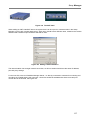
Getting Started - RealShot Manager Basics
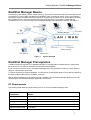
RealShot Manager Basics
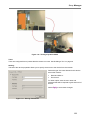
Cameras (e.g. SNC-RZ30), camera control units (e.g. SNT-V304), audio boxes and input/output devices are
connected to a Local or Wide Area Network (LAN/WAN); often via a network switch. One or more Network
File System (NFS) compatible server(s) can also be connected to the network to act as storage for the video
files recorded from the cameras and audio files from the audio boxes. The system is configured and
controlled from one or more PCs that run the RealShot Manager client application software. See Figure 7.
Figure 7
System Example
RealShot Manager Prerequisites
A software license is required to run RealShot Manager. If the application is started without a valid license
file in place then only reduced evaluation functionality will be available.
If you are using a previous version of RealShot Manager with a dongle, please contact your Sony dealer to
apply for a free software license file.
To ensure access to the network database, you will need up to date ODBC drivers. These will be installed by
the setup program (alternatively run MDAC_TYP.exe).
Both of these installations can be carried out after installation of the RealShot Manager application but are
required before the RealShot Manager application can be used.
PC Requirements
The following table details the requirements for a PC to run as a RealShot Manager client.
Component
Operating System
Option
Windows® 2000, 2003 Server or XP
P
P
®
Processor
Pentium 4 - Processor 2.4 GHz or higher is recommended
Memory
512 MB RAM minimum
Video card
Supporting 1024 x 768 at 16/24bit colour depth
Network Interface card
100 Mbit/s
P
P
7
Getting Started - Software Installation
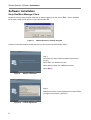
Software Installation
Sony RealShot Manager Client
Double-click on the setup program setup.exe or open the start menu and click on Run…. Enter <CDROM
Drive Letter>:\setup.exe as shown in Figure 8 and select OK.
T
T
Figure 8
T
T
Manual Execution of Setup Program
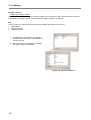
Follow the instructions below; please note that you will require local administrator rights:
Step 1:
Shut down any other windows programs that may be
running.
Select OK in the Welcome window.
Select Setup to begin the installation process.
Select Next >.
T
Figure 9
T
Setup Confirmation
Step 2:
Read the End User License agreement and select Yes if
you agree to be bound by the terms.
T
Figure 10
8
License Agreement
T
Getting Started - Software Installation
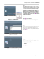
Step 3:
Select Browse and navigate to a folder in which to
install the software; the default location is typically:
C:\Program Files\Sony\Sony RealShot Manager
Note that the drive letter will depend on the
installation of the Operating System and that the
default path can be modified during installation, an
example of a modified path is shown in Figure 11.
If the directory does not exist, select OK to confirm
creation of the directory.
T
T
Step 4:
Select OK to save the path.
T
Figure 11
Installation Path
T
Select Next > to move to the next Setup screen.
T
T
Step 5:
Enter the name of the Program Folder where the
shortcut icon to RealShot Manager should be
installed. The default is: Sony RealShot Manager.
Select Next >.
T
Figure 12
T
Set Folder
Step 6:
Select the type of RealShot Manager you wish to
install from the following:
•
•
•
Standard (the default)
Controller
Viewer
Select Next >.
T
Figure 13
T
Select Installation Type
9
Getting Started - Software Installation
Step 7:
The English version of the RealShot Manager user
interface is installed by default, Select any additional
language(s) you require.
Select Next >.
T
Figure 14
T
Set UI Language
Step 8:
Select the language you require for the PDF of the
User and Administration guide.
Select Next >.
T
Figure 15
T
Set Guide Language
Note:
If you are upgrading from a recent version of
RealShot Manager or using the compact install file,
then you will see this warning message. The PDF
file for the User and Administrator guide will not be
updated on this occasion. You will need to obtain
the user guide separately from Sony.
Select OK to close the dialog and continue with the
setup procedure.
T
Figure 16
10
Guide Copy Error
T
Getting Started - Software Installation
Step 9:
Select Finish to complete the installation of
RealShot Manager.
T
T
Note: You will need to obtain a software license file
before using RealShot Manager.
Figure 17
End RealShot Manager Installation
Sony RealShot Manager Server
Installation of the Windows or Linux server-only RealShot Manager application is covered in ‘Installing
RealShot Manager Server’ on page 84.
Starting RealShot Manager
When the application is run for the first time, see User Guide section ‘Launching the Application’, there will
be no initial configuration, the following steps are needed to get a basic working configuration:
1) Register Cameras.
This is achieved using the Setup Manager; see the section entitled ’Setup Manager’ in the RealShot
Manager Administrator Guide. The following compatible Sony video network cameras (both PAL and NTSC
models) are supported:
•
SNC-RZ30 Video Network Pan-Tilt-Zoom Camera. See Figure 1.
•
SNC-VL10 Video Network Camera. See Figure 2.
•
SNT-V304 Video Network station. See Figure 4.
•
SNT-V501 Video Network station. See Figure 4.
•
SNT-V504 Video Network station
•
SNC-Z20 Video Network Zoom Camera.
•
SNC-CS3 Video Network Camera.
•
SNC-P1 Video Network Camera (for Motion JPEG or MPEG-4). See Figure 5.
•
SNC-DF40 Video Network Camera (for Motion JPEG or MPEG-4). See Figure 6.
Administrators: refer to the individual camera user guides for details on how to assign IP addresses.
1) Create a Screen Layout; see the section entitled ‘Layout Editor’ in the RealShot Manager
‘Administrator Guide’.
2) Assign Cameras to Monitor Windows. See section ‘Changing Cameras in the Monitoring Layout’ in the
RealShot Manager ‘User Guide’.
3) Create user accounts. See ‘Manage User Accounts’ in the RealShot Manager ‘Administrator Guide’
for details of how to create and manage user login details.
11
Getting Started - Troubleshooting the Client Installation
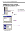
Troubleshooting the Client Installation
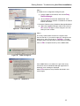
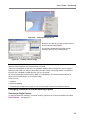
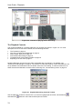
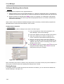
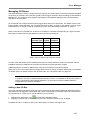
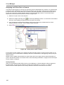
‘ODBC not set up during Initial Software Configuration’
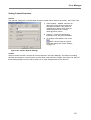
Before using the Sony RealShot Manager software a Microsoft Access
Data Source Name (DSN) must be created. To do so, perform the
Step 1:
Open the ODBC Data Sources
control panel applet.
Open the Control Panel and select
Administrative Tools/Data Sources
(ODBC).
T
T
following:
Figure 18
ODBC Data Source
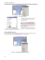
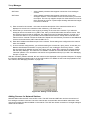
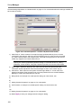
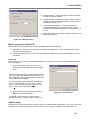
Step 2:
In the ODBC DSN Dialog Box select the System DSN tab
and click on Add....
T
Figure 19
T
Data Source Name
Step 3:
Select Microsoft Access Driver (*.mdb) from the list of data
source drivers and click on Finish.
T
Figure 20
12
Access Drivers
T
Getting Started - Troubleshooting the Client Installation
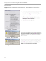
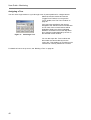
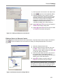
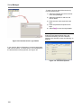
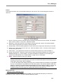
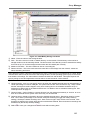
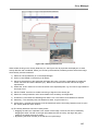
Step 4:
The Data Source configuration dialog will open.
1) Enter the Data Source Name; this must be Sony
RealShot Manager.
T
T
2) Click on Select to locate the database file. If the
RealShot Manager software is installed in the default
location this will be:
C:\Program Files\Sony\Sony RealShot Manager\Database
T
T
Figure 21
Link to the DB
3) Select the ‘RealShot Manager.mdb’ file and click on
OK. Click on OK again to save changes to the new
DSN you have created.
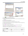
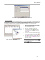
Step 5:
The newly created DSN is listed in the System Data
Sources List Box. If you need to make any changes to this
data source, select it and click on Configure… to make
changes. Refer to the Microsoft Access manual for details.
Click on OK to complete the set up of the ODBC DSN.
Figure 22
ODBC Configured
If the ODBC DSN is not created or is given the wrong
name then when the RealShot Manager application is
started an error message is displayed.
Select OK and perform the procedure described in this
section again.
Figure 23
ODBC Error
13
Getting Started - Troubleshooting the Client Installation
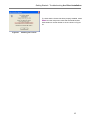
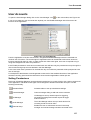
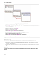
License Error
If RealShot Manager is started without a valid software license, the message shown in Figure 24 will be
displayed.
Figure 24
•
To resolve this, obtain a license file from Sony and place
it in the same directory as the RealShot Manager
executable. Select Retry to continue when you have
installed the license file.
•
If you do not have a license then you can run an
evaluation version of the program by selecting either
Evaluate or 30 Days Mode (either option subject to
restrictions as shown in Figure 24).
•
Select Exit to leave the application.
License Error
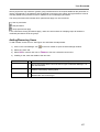
If the license file installed on this machine has expired then
you will see a message like this. Select OK to continue and
obtain a new license file. To run the RealShot Manager
application in evaluation mode, delete the old license file
from the machine.
Figure 25
Out of date License
If the license file on this machine is not valid for the current
version of software, then you will see a message like this.
Select OK to continue and obtain a new license file. To run
the RealShot Manager application in evaluation mode,
delete the invalid license file from the machine.
Figure 26
14
Invalid License
Getting Started - Troubleshooting the Client Installation
To check that the license has been properly installed, select
About from the Help menu check that the Serial Number
field contains a number similar to the one shown in Figure
27.
Figure 27
Checking the License
15
Getting Started - End User License Agreement
End User License Agreement
SONY Corporation End-User License Agreement
Sony RealShot Manager Application
THIS PRODUCT IS FOR PROFESSIONAL USE
IMPORTANT - READ BEFORE USING
END-USER LICENSE AGREEMENT
FOR SOFTWARE PROGRAM AND DOCUMENTATION
YOU SHOULD CAREFULLY READ THE FOLLOWING AGREEMENT BEFORE USING THE PROGRAM
AND THE ACCOMPANYING DOCUMENTATION. USING THE PROGRAM AND THE ACCOMPANYING
DOCUMENTATION INDICATES YOUR ACCEPTANCE OF THIS AGREEMENT. IF YOU DO NOT AGREE
WITH THIS AGREEMENT, YOU SHOULD NOT USE THE PROGRAM AND THE ACCOMPANYING
DOCUMENTATION.
GENERAL
SONY Corporation and its licensors furnish this program and the accompanying documentation and
licenses their use to you, all as provided in this Agreement.
LICENSE
Under this Agreement, Sony and its licensors grant you a limited license to use the program and the
accompanying documentation for the purposes outlined in that documentation, and not for resale or
any other purpose.
YOU AGREE NOT TO MODIFY OR DISASSEMBLE THE PROGRAM OR THE ACCOMPANYING
DOCUMENTATION, IN WHOLE OR IN PART, EXCEPT AS EXPRESSLY PROVIDED FOR IN THIS
AGREEMENT OR UPON SONY'S PRIOR WRITTEN APPROVAL. IN ADDITION, YOU AGREE NOT TO
TRANSFER, LICENSE OR DISCLOSE THE PROGRAM OR THE ACCOMPANYING DOCUMENTATION
IN WHOLE OR IN PART, TO ANY THIRD PARTY WITHOUT SONY'S PRIOR WRITTEN APPROVAL.
This license is effective until terminated. You may terminate it at any time by giving Sony written
notice to that effect. Sony and its licensors may terminate it if you fail to comply with this Agreement
by giving you like notice. Upon termination, you must destroy the program and the accompanying
documentation and all copies you have made of them. In addition, upon termination you will have no
recourse against Sony or its licensors for your inability to use the program or the accompanying
documentation.
EXCLUSIONS OF WARRANTIES
16
Getting Started - End User License Agreement
THE PROGRAM AND THE ACCOMPANYING DOCUMENTATION ARE FURNISHED TO YOU "AS IS"
WITHOUT WARRANTY OF ANY KIND. SONY AND ITS LICENSORS DO NOT WARRANT THAT THE
PROGRAM OR THE ACCOMPANYING DOCUMENTATION WILL MEET YOUR REQUIREMENTS OR
THAT THE OPERATION OF THE PROGRAM WILL BE UNINTERRUPTED OR ERROR FREE. SONY
AND ITS LICENSORS DISCLAIM AND EXCLUDE ALL WARRANTIES, EXPRESS OR IMPLIED, WITH
RESPECT TO THE PROGRAM AND THE ACCOMPANYING DOCUMENTATION, INCLUDING, BUT NOT
LIMITED TO, ANY AND ALL IMPLIED WARRANTIES OF MERCHANTABILITY, FITNESS FOR A
PARTICULAR PURPOSE AND/OR ANY WARRANTY WITH REGARD TO ANY CLAIM OF
INFRINGEMENT THAT MAY BE PROVIDED IN SECTION 2-312(3) OF THE UNIFORM COMMERCIAL
CODE AND/OR ANY OTHER COMPARABLE STATE STATUTE.
LIMITATION OF LIABILITY
THE PROGRAM AND THE ACCOMPANYING DOCUMENTATION ARE FURNISHED TO YOU FOR USE
AT YOUR OWN RISK. SONY AND ITS LICENSORS WILL NOT BE LIABLE, AND YOU WILL HAVE NO
REMEDY FOR DAMAGES FOR ANY CLAIM OF ANY KIND WHATSOEVER, CONCERNING YOUR USE
OF THE PROGRAM OR THE ACCOMPANYING DOCUMENTATION, REGARDLESS OF LEGAL
THEORY, AND WHETHER ARISING IN TORT OR CONTRACT. IN NO EVENT WILL SONY OR ITS
LICENSORS BE LIABLE TO YOU FOR ANY SPECIAL, INDIRECT, INCIDENTAL, OR CONSEQUENTIAL
DAMAGES OF ANY KIND, INCLUDING, BUT NOT LIMITED TO, COMPENSATION, REIMBURSEMENT
OR DAMAGES ON ACCOUNT OF THE LOSS OF PRESENT OR PROSPECTIVE PROFITS, LOSS OF
DATA, OR FOR ANY OTHER REASON WHATSOEVER FOR AND WITH RESPECT TO THE SOFTWARE
AND THE ACCOMPANYING DOCUMENTATION.
MISCELLANEOUS
Some jurisdictions may not allow exclusions or limitations of incidental or consequential damages,
or allow limitations on implied warranties, so the above exclusions and limitations may not apply to
you as written. However, in those instances, you agree that the above exclusions and limitations are
enforceable to the fullest extent permitted by the law of that jurisdiction and the governing law
referred to below. You acknowledge that as between you, Sony and its licensors, Sony and its
licensors own all right, title and interest, including but not limited to, all copyrights, trade secret and
other intellectual property, in and to the program and the accompanying documentation. You further
acknowledge that Sony's licensors are direct and intended third party beneficiaries of this
Agreement and may enforce it directly against you. If you are a governmental entity, your use,
duplication or disclosure of the program and the accompanying documentation are subject to the
restrictions set forth in subparagraphs (c)(1) and (c)(2) of the Commercial Computer Software clause
at FAR 52.227-19, and subparagraph (c)(i)(ii) of the Rights in Technical Data and Computer Software
clause at DOD FAR 252.227-7013 and any comparable federal, state or local law or regulation and, for
this purpose, the manufacturer is SONY Corporation located at the address referred to below. You
may not export the program and the accompanying documentation in violation of the export control
laws of relevant countries. This Agreement will be governed by the laws of the United States of
America and the State of New Jersey. If any part of this Agreement is held invalid or unenforceable,
the other parts will remain valid.
Should you have any questions concerning this Agreement please see the User Guide for contact
details.
YOU ACKNOWLEDGE THAT YOU HAVE READ THIS AGREEMENT, UNDERSTAND IT AND AGREE TO
BE BOUND BY IT. YOU FURTHER AGREE THAT IT IS THE COMPLETE AND EXCLUSIVE
STATEMENT OF AGREEMENT BETWEEN YOU AND SONY AND ITS LICENSORS CONCERNING THE
PROGRAM AND THE ACCOMPANYING DOCUMENTATION AND THAT IT SUPERSEDES ANY
17
Getting Started - End User License Agreement
DEMONSTRATION, ADVERTISEMENT, PROPOSAL OR PRIOR AGREEMENT, ORAL OR WRITTEN,
AND ANY OTHER COMMUNICATIONS BETWEEN YOU AND SONY OR BETWEEN YOU AND ANY
OTHER PARTY RELATING TO THE PROGRAM AND THE ACCOMPANYING DOCUMENTATION.
Save this Agreement for future reference.
© 2002, 2005 Sony Corporation
Sony All rights reserved. Reproduction in whole or in part without written permission is prohibited.
18
User Guide - Launching the Application
User Guide
Launching the Application
To start the RealShot Manager application, you can either:
1) Use the windows Start menu or
2) Double click on the desktop shortcut.
From the windows Start menu,
select:
1) Programs
2) Sony RealShot Manager
3) RealShot Manager
Figure 28
Use of the Start Menu
If a shortcut like the one shown in Figure 29 exists on your desktop, you can double click on it to
launch the RealShot Manager application.
Figure 29
Desktop Shortcut
19
User Guide - Launching the Application
Creating a Desktop Shortcut
If you do not have a desktop shortcut for RealShot Manager, follow the procedure below to create
one:
Step 1:
Open the Start menu for RealShot
Manager as if to launch the
application but right-click on the
‘RealShot Manager’ menu entry to
open the pop-up menu.
Step 2:
Select ‘Create Shortcut’ to add a
shortcut to the Start menu. By default
this shortcut is named ‘RealShot
Manager (2)’.
Figure 30
RealShot Manager Menu Items
Step 3:
Select the shortcut ‘RealShot
Manager (2)’ with the left mouse
button and drag to the desktop.
Step 4:
You can add the version number to
the end of the name as shown in the
example in Figure 31.Right-click on
the new desktop icon and select
Rename. Delete the ‘(2)’ and add the
version number to the end of the
name.
Select Return to save your changes
to the name.
Figure 31
Renaming the Shortcut
Dealing with Licensing Issues
As the RealShot Manager application starts, it will look for the presence of a license file. If the
RealShot Manager application does not detect a license file required to run the software, the
message shown in Figure 24 will appear.
20
User Guide - Navigating the User Interface
Contacting Sony
If you have any questions regarding licensing of RealShot Manager, please contact your local Sony
dealer.
Navigating the User Interface
The RealShot Manager user interface is an example of a Graphical User Interface (GUI), where
practicable the individual windows support standard Microsoft Windows behaviour.
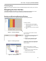
Resizing and Minimizing/Maximizing Windows
The windows opened during use of RealShot Manager can be arranged as follows:
To resize a window:
1) Place the cursor over an edge or
corner of the window until the dragarrow appears.
2) Drag the window to the new required
size.
Figure 32
Resizing a Window
You can also vary the width of columns
within a window:
1) Place the cursor over the join between
two columns until the drag-arrow
appears.
2) Drag the column boundary until the
column is the required new width.
Figure 33
Resizing a Column
To auto-size a column to its contents, left
double-click on the join to the right of the
column heading.
Within a window made up of multiple
panes, you can adjust the area occupied by
each pane:
1) Place the cursor over the edge of the
pane you wish to resize.
2) Drag out to the required width.
Figure 34
Resizing a Pane
21
User Guide - Navigating the User Interface
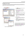
Each of the application windows has the
standard windows controls for manipulation
of windows:
1) Minimize
2) Restore Down
Figure 35
Window Management - 1
3) Close
However, in the secondary windows, the
minimize function is disabled. Only the
whole application can be put into the
background to be accessed via a button on
the Windows Start Bar.
If you restore down a window, you can
return it to its original size by selecting
maximize.
1) Minimize
Figure 36
Window Management - 2
2) Maximize
3) Close
Selecting a Colour
The colour palette allows you to select a colour from the basic range or to define your own custom
colours. See Figure 37:
Figure 37 The Colour Palette
1) You can select any colour from the 'Basic Colours:' by clicking on the colour required and then
OK.
2) If you wish to define a custom colour, drag the colour selector until the colour you require is
visible in the 'Colour/Solid' box.
3) You can refine the shade of the selected colour by dragging the arrow up and/or down to
make the shade lighter or darker.
4) An alternative is to type in the RGB values for the colour directly into the boxes provided.
5) Select Add to Custom Colours to register the new colour.
22
User Guide - Navigating the User Interface
6) Select OK to exit the ‘Colour’ dialog and save your changes. Select Cancel to exit without
saving.
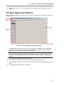
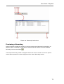
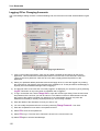
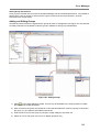
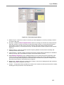
The Main Application Window
When the RealShot Manager application is first launched, the default layout is displayed, as shown
by Figure 38:
Figure 38
The Default Main Application Window
1) The Main Toolbar. Some of the functions of this toolbar are protected by access rights and
may therefore not be available. The View and Help menus. These are clearly visible and
ready for use. If this is not the case then press Shift+F11.
Note: Shift+F11 only works when NOT in Full Screen Mode. If in Full Screen Mode, first
leave this mode (Shift+Enter) and then press Shift+F11. If you do not have rights to leave
Full Screen mode then Shift+Enter will have no effect. In this case login as a different user
(Ctrl+L).
2) The Toolbars for individual areas of functionality.
3) The Layout Editor Toolbar. This provides tools for creating monitor layouts.
4) The Status Bar. This gives a summary of the current activities of the application and recent
errors.
5) The Central area of the window. This is empty.
23
User Guide - Navigating the User Interface
Note: You can also use the Full Screen
button on the main toolbar to toggle
between the normal view and full-screen. However, with default permissions you can
only go from window to full-screen, not back again. To return from full screen requires
additional privileges, see your System Administrator to ask for help or login as a
different user with the appropriate privileges (Ctrl+L).
To be able to use many of the features of RealShot Manager, you will have to ask your
System Administrator to create one or more user accounts.
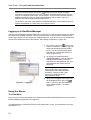
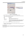
Logging in to RealShot Manager
The first time the RealShot Manager application is launched, no user accounts exist and by default
all functions are available. However, as soon as the first user account has been created you will
need to log in before you can use all your assigned functions. If you do not log in you will still have
access to the default functions of the software. See ‘Setting Permissions’ on page 105.
on the main
1) Click on the ‘Login’ icon
toolbar or select Ctrl + L. Enter your user
name and password and select OK to
log in. If you do not have these details
then see your system administrator to
obtain a new account.
2) To change your password select
Change Password…, this will open the
change password dialog. Enter your
user name and old password, then your
new password and confirm the new
password.
You may be prompted to enter a password
when you first log in if the System
Administrator has made passwords
mandatory. See the section ‘User
Accounts’ on page 105 of the
Administrator’s Guide.
Figure 39
Logging In
3) When you are logged in the ‘Login’ icon
.
will be displayed as an open lock
Note: If you select the open padlock or
Ctrl+L whilist logged in, you will be
logged out.
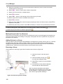
Using the Menus
The View Menu
The View menu controls the display of the windows and toolbars associated with the functions of the
RealShot Manager application. See Figure 40.
To toggle between normal and full-screen mode, select Shift + Enter. To show/hide the menu bar,
select Shift + F11.
24
User Guide - Navigating the User Interface
The Show Toolbar Title when Docked option has a toggle action and determines whether toolbars
are displayed with or without their title bars when docked. See ‘Docking’ on page 26.
The display of the individual toolbars and the Status
Bar is controlled via a toggle action. Select the
toolbar name to mark it with a ‘9’ and make it
visible; select the same toolbar again to remove it
from the main window.
The visibility of each of the toolbars can also be
controlled from the Main toolbar of the RealShot
Manager application. See ’The Main Toolbar’ on
page 26.
The Playback and Comment toolbars each have two
display options; Small and Long. These options
allow you to choose between two layouts for the
toolbar.
Select Show Playback Toolbar/Small to display the
Playback toolbar in the ‘small’ format. Select Show
Playback Toolbar/Long to display the Playback
toolbar in the ‘long’ format.
The Long option makes the toolbar full width within
the window and so minimises its vertical height.
Figure 40
The View Menu
The Small option arranges the controls within the
minimum square area; this can be useful if many
toolbars are required to be visible at the same time.
The Comment toolbar format can be selected in the
same way.
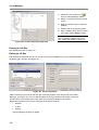
The Help Menu
The Help menu provides version information for the RealShot Manager application.
Select Help/About RealShot Manager… to display version and configuration information as shown
in Figure 27 on page 15.
Select OK to close the ‘About Sony RealShot Manager’ dialog.
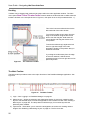
Using the Toolbars
Much of the functionality available through RealShot Manager is available through specific toolbars
that can be arranged on the screen as you wish.
25
User Guide - Navigating the User Interface
Docking
Toolbars can be dragged and positioned anywhere within the main application window. The View
menu option Show Toolbar Title when Docked controls whether the blue title bar is visible when the
toolbar is docked. In the example shown in Figure 41, this option is set to off (not marked with a ‘9’).
This is the Comment toolbar docked to the
left-hand side of the main window.
To move the toolbar, drag it away from the
edge of the window using the left mouse
button over the drag bar. Hold down the
mouse button and drag the window to its
new position.
To dock the toolbar drag it against the left
hand or right hand edge of the main
application window in the position that you
would like it docked.
If you drag the toolbar away from the edge
of the main window, it will become a
separate window in its own right and can be
placed anywhere.
Figure 41
The Comment Toolbar
The Main Toolbar
The Main toolbar provides access to the major functions of the RealShot Manager application. See
Figure 42.
Figure 42
The Main Toolbar
1) Login – See ‘Logging in to RealShot Manager’ on page 24.
2) Select Layout – Allows the selection and subsequent display of previously created monitor
layouts. The selected layout controls the appearance of the monitor window. See ‘Creating a
New Layout’ on page 162. The drop-down list will be empty if no monitor layouts have
previously been created.
3) Layout tools - These allow you to control the arrangement of monitors for viewing camera
images. See ‘Selecting a Monitoring Layout’ on page 35. The five icons are:
26
User Guide - Navigating the User Interface
• Open Layout
• Toggle Auto Layout Change
• Load Default Layout
• Load Previous Layout
• Load Next Layout
4) Schedule Editor - Allows you to setup and modify daily and weekly schedules of events for
each camera. These events can include monitoring, recording and purging of previously
recorded files. See ‘The Schedule Editor’ on page 49.
5) Search Recordings - Provides a browse facility to locate recordings for viewing. See
‘Searching for Recordings’ on page 64.
6) Setup Manager - Allows a user with administrator rights to add and modify cameras, I/O Boxes,
Audio Devices, Device Groups and Remote Servers. See ‘Setup Manager’ on page 111.
7) Action Editor – Allows you to configure the actions to be triggered if a sensor input is activated,
e.g. if a door sensor detects that a door has been opened. See The Action Editor on page 153.
8) User Manager - Allows a user with administrator rights to add and modify user accounts and
permissions. See ‘’ on page 102 for further details.
9) General Settings - Allows a user with administrator rights to modify application-wide settings
such as directories for recorded files, log file settings and the default monitoring setup. See
‘General Settings’ on page 91.
Camera Properties – This icon is disabled until a camera is selected in the monitoring window. See ‘
27
User Guide - Navigating the User Interface
10) Setting Camera Properties’ on page 121.
11) Toggle <Toolbar> Controls. These enable the display or hiding of function-specific toolbars.
You can also show/hide the toolbars using the View menu options.
1) Toggle Recorder Toolbar
2) Toggle Playback Toolbar
3) Toggle Audio Toolbar
4) Toggle Pan & Tilt Toolbar
5) Toggle Preset Toolbar
6) Toggle Tours Toolbar
7) Toggle Output Control Toolbar
Figure 43
The Toolbar Controls
8) Toggle Comment Toolbar
9) Toggle Layout Editor Toolbar
10) Toggle Custom Toolbar
Depress the button to display the related
toolbar.
12) Logging Controls – To view and setup logs, use the Logging Window, Logging Control, Alarm
Window and User Log Window icons. See ‘Logging’ on page 185. Modifying some of the
logging settings requires administrator rights.
These windows present information to the user
on the status and progress of events in
RealShot Manager, see ‘Troubleshooting’ on
page 185.
1) Logging Window
2) Logging Control
3) Alarm Window
Figure 44
Logging Controls
4) User Window
13) Full Screen – This icon toggles between normal mode and full-screen mode. In full-screen
mode the main application window is expanded to fill the screen; the Title Bar, Menu Bar and
Status bar are removed to make as much space as possible for the monitor windows and the
toolbars.
Note: The icons labelled 14) and 15 in Figure 42 are not part of the Main toolbar but part of the
Custom Toolbar (see below). The two toolbars may be docked so that they appear as one.
The Custom Toolbar
A Custom Toolbar may be placed adjacent to the Main Toolbar (see Figure 42) containing icons to
activate further applications. This Custom toolbar may also be separate from the Main toolbar and
appear anywhere within the Main Window.The links shown as 15) and 16) are included as part of
the RealShot Manager application but others may be added, see ‘External Application Integration’
on page 102 of the Admistrator’s Guide:
28
User Guide - Navigating the User Interface
1) EZPlugger - Exports the RealShot Manager device configuration to EZPlugger, a separate
software application built around a group of Wizards designed to assist you in the
configuration, firmware update and validation of Sony Digital Surveillance products prior to
and during the installation process. Sony’s IP Monitoring Cameras connect directly to the
network while the Video Network Station ( or gateway) allows use of existing analogue
cameras in an IP network environment. EZPlugger provides a step by step approach to
building device configurations, downloading firmware updates and setting device parameters.
Note: EZPlugger is a separate application to RealShot Manager and requires a separate
installation and registration procedure.
2) Email Notification – Enables the sending of e-mails to notify specified users when an alarm is
triggered. For details of how to configure alarms for e-mail notification, see ‘Alarm Notification
Integration’ on page 104.
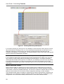
The Schedule Editor Toolbar
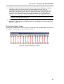
Selecting the Schedule Editor button from the main toolbar opens the schedule editor. The toolbar for
the schedule editor provides you with the following functions:
Figure 45
The Schedule Editor Toolbar
29
User Guide - Navigating the User Interface
1) View as List – switches the window from the weekly calendar to the activities list.
2) View as Week – switches the window from the activities list to the weekly calendar.
3) Toggle Form – Displays/Hides the activities form.
4) New Schedule – Clears the schedule of recordings for the currently selected camera or
group.
5) Apply Schedule – Saves changes to the recording schedule for the current camera or group.
6) Copy Schedule – Copies an entire schedule for a camera or camera group into a schedule
paste buffer. In the case of copying from a group the resultant schedule is the combination of
all events for all cameras in the group.
7) Paste Schedule – Pastes the contents of the schedule paste buffer. The pasted schedule can
be applied to a single camera or a camera group. Select the destination camera or group
prior to pasting the schedule.
8) Insert Date/Time Item – Allows you to schedule a single activity, i.e. is only enabled in the List
View.
9) Insert Recurrent Item – Allows you to schedule a recurrent activity. This button is active in
both the Week View and the List View.
10) Insert Date/Time Motion Detection Job Item – Allows you to schedule an event to monitor for
movement as configured for the selected camera in the Setup Manager.
11) Insert Recurrent Motion Detection Job Item – Allows you to schedule a recurrent event to
monitor for movement as configured for the selected camera in the Setup Manager.
12) Insert Date/Time Cleanup Job Item – Allows you to purge recordings from a particular camera
or group at a particular time and date.
13) Insert Recurrent Cleanup Job Item – Allows you to schedule a job to purge recordings from a
particular camera or group regularly.
The following items are only visible and therefore available if a license for the separate retail
module has been loaded:
14) New Retail Item – Adds a date/time event to activate the retail module if configured.
(Configuration of the retail module requires a license file with the retail module enabled and the
retail module checkbox in the ‘General Settings’ to be checked.)
15) Add Recurrent Retail Item - Adds a regular event to activate the retail module if configured.
16) Remove Item – Removes the activity currently selected from the schedule.
The use of these functions is described in ‘Scheduling Recordings’ on page 49.
30
User Guide - Navigating the User Interface
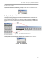
The Recorder Toolbar
The Recorder Toolbar, see Figure 46, allows you to start and stop manual recordings and to take
snapshots. For further details, see ‘Recording’ on page 48.
Figure 46
The Recorder Toolbar
The Playback Toolbar
The Playback Toolbar provides functions to control the playback of previously recorded files. See
‘Searching for Recordings’ on page 64.
Once the toolbar is open, see Figure 47, you can use the ‘Toggle Toolbar Size’ button
to move
between the short and long versions of the controls. Choose the format that fits your current screen
layout.
Figure 47
The Playback Toolbar Versions
The Audio Toolbar
The audio toolbar allows you to select the source of audio that is monitored and turn the audio
monitoring on and off (audio muting). See ‘Monitoring Audio’ on page 79.
Figure 48
The Audio Toolbar
31
User Guide - Navigating the User Interface
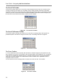
The Pan & Tilt Toolbar
The Pan &Tilt toolbar allows you to control the camera angle and zoom level of a camera you are
currently monitoring. See Figure 49. For details of how to setup camera control see ‘Controlling
Cameras’ on page 43.You must have been assigned the appropriate rights to manipulate the chosen
camera. If you do not, then these controls will remain disabled. If the camera does not support pan,
tilt and zoom functions then these buttons will also remain disabled.
Figure 49
The Pan & Tilt Toolbar
The Pan & Tilt Presets Toolbar
The ‘Preset’ toolbar, see Figure 50, allows you to use and set camera presets. Each preset is a
predefined position view that can be given a name. See ‘Controlling Cameras’ on page 43.
Figure 50
The Presets Toolbar
The Tours Toolbar
A ‘Tour’ is made up of a list of presets, with a duration to hold the image for each preset in the list
and a duration to move from one position to the next after holding. See ‘Building a Tour‘ on page 46.
Tours are only available for cameras with Pan, Tilt and/or Zoom functions, see ‘Camera Settings
dependent on Camera Model’ in the Administrator Guide for details of the capabilities of each
supported model of camera.
You can build a tour from existing presets or specify new ones from the ‘Tours’ builder.
Figure 51
32
The Tours Toolbar
User Guide - Navigating the User Interface
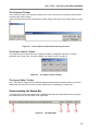
The Comment Toolbar
The ‘Comment’ toolbar, see Figure 52, allows you to enter comments for a particular camera whilst
monitoring the camera output.
These comments can be later read using the Search facility. See ‘Searching for Recordings’ on page
64.
Figure 52
The Comment Toolbar (short and long versions)
The Output Control Toolbar
The ‘Output Control’ toolbar allows you change the states of configured outputs for a camera
selected in the monitor view. For further details, see ‘Output control’ on page 47
Figure 53
The Output Control Toolbar
The Layout Editor Toolbar
The ‘Layout Editor’ toolbar allows a RealShot Manager administrator to design monitor layouts and
assign cameras and actions to each monitor window. See ‘Housekeeping’ on page 160.
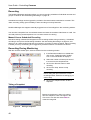
Understanding the Status Bar
The Status bar is found at the bottom of the RealShot Manager main application window and gives
information about the current status of the application.
Figure 54
The Status Bar
33
User Guide - Monitoring
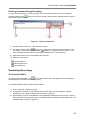
1) General application status, defaults to ‘Ready’ when the application is not busy. If there is a
problem with the application then a warning message will appear in this area. Errors will be
accompanied by an icon . See the example shown in Figure 54.
2) User currently logged in, defaults to ‘No User’ if not logged in.
3) Current Date
4) Current Time
Monitoring
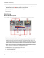
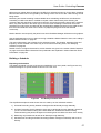
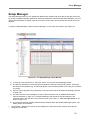
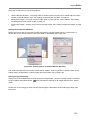
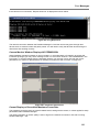
Monitor Window Objects
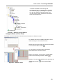
When creating a Monitor Window layout a number of different objects can be added to layout.
Figure 55 Monitor Window Objects
1) Camera Monitor Windows – Used to display images from cameras, playback previously
recorded video clips and capture snapshots.
2) Hotspot Camera Monitor Window – Used to display a duplicate image from one of the other
camera monitor windows. The hotspot monitor window would generally be larger than the
other camera monitor windows and is used to see any image in more detail. Click on any
camera monitor window (1) and the picture is also displayed in the hotspot monitor. In a dual
screen configuration, the hot-spot monitor can be configured to be a full-screen image on the
second monitor, see ‘General Settings’ on page 91 in the Administrator’s guide for details.
3) Image Object – JPEG, BMP and EYE (wavelet) image files may be displayed on the layout.
These objects are created using a graphic editing application and then loaded into the layout.
Image objects may be made active by assigning an action to them.
The following actions can be configured for an image object:
• Switch the camera displayed in a monitor.
•
Switch to a different layout.
•
Send a command using external control.
When an action is assigned to an image object, clicking on that object will execute the action.
34
User Guide - Monitoring
4) Background Image – JPEG, BMP and EYE image files may be displayed on the background
of the Monitor Window. These images can be tiled, centred or stretched to fill the whole
window.
5) Background Colour – the colour of the background can be configured (the default colour is
grey).
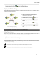
Creating a Monitoring Layout
When RealShot Manager is first started after installation, no monitor layouts are defined. A RealShot
Manager administrator can create a monitor layout for your installation using the Layout Editor. See
‘Creating a New Layout’ on page 162.
Layouts show camera images and graphics arranged in a defined way. For example, if you are
monitoring offices across Europe, you may find it convenient to arrange small monitors or graphics of
each camera over a map of Europe and have one large ‘hot-spot’ monitor for viewing the image from
a selected camera.
Selecting a Monitoring Layout
To select between previously designed monitor layouts, you can use any of the following methods:
1) Use the drop-down list from the main
toolbar and select the layout from the
list.
Figure 56
Select Layout
2) Select
from the main toolbar and
choose the layout from the list. Select
OK to go to the selected layout.
Note: A RealShot Manager administrator can
create a default layout; see ‘
Enabling the Layout Editor Toolbar’ on page
162. To return to the default layout select
from the main toolbar.
Figure 57
Layout List
3) Select the ‘Toggle Auto Layout Change’ icon
through a predefined list of prepared layouts.
to enable or disable automatic cycling
Note: A RealShot Manager administrator can create a list of layouts to be displayed in order, see
‘Layout Settings’ on page 102 of the Administrator’s Guide.
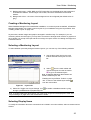
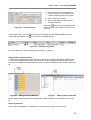
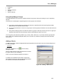
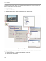
Selecting Display Items
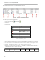
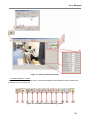
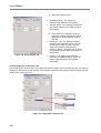
To modify the information about the connection that is visible in a monitor window, select a camera monitor
window.
35
User Guide - Monitoring
•
•
•
•
Select the View from the right-click pop-up menu.
From the sub-menu, enable the information that you would like to be visible in the monitor window. Each
of these menu items has a toggle action, items marked with a ‘9’ are visible. The mapping between the
menu items and the displayed information is shown in Figure 58. However, you would not normally see
all of the example information at the same time. For example, the status ‘NO CONNECTION’ and the
bandwidth 64kbps are mutually exclusive because the bandwidth will only be displayed for a valid
connection.
The motion detection are markings are only visible when one of the motion detection configurations has
been activated during a scheduled motion detection event.
If NO CAMERA is displayed in the Monitor Window, use either the Select Camera… or Select Multiple
Cameras… option to allocate one or more cameras for monitoring.
Figure 58
Selecting Display Items
Note:
The frames per second (fps) value shown labelled as ‘4’ in Figure 58 is not a fixed, continuous value
but an average value taken over a time interval.
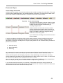
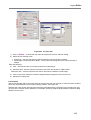
Scaling the Monitored Image
To change the scaling of the image in a monitor window, right-click on a monitor and select one of
the scaling options from the pop-up menu.
The scaling options are as follows:
•
Scale To Window
•
Smart Scale
•
Keep Aspect
•
Smooth Scaling
The effect of each of these options is described
in section ‘Monitor Window Object Scaling’ on
page 178 of the Administrator Guide.
Figure 59
36
Scaling Camera Images
User Guide - Monitoring
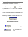
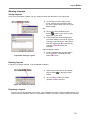
Freezing the Monitored Image
You can freeze the image in a monitor window to take a longer look at one frame:
To freeze the image in a monitor window as a
still, right click on a monitor and select Freeze
from the pop-up menu. A ‘9’ will appear
against the Freeze menu item.
This menu item has a toggle action, to return to
normal monitoring select Freeze again to clear
the ‘9’.
Figure 60
Freezing a Camera Image
Whilst the freeze is active, the image in the
monitor is frozen (still) and ‘Freeze’ is
displayed in the monitor.
Note: This does not save the still image to
disk. If you wish to take a snapshot of a
camera image. See ‘Saving the Monitored
Image’ on page 38.
Figure 61
Camera image with ‘Freeze’
Updating the Frame Rate
To vary the displayed frame rate of the image in a monitor window, right click on a monitor and select
Update Speed from the pop-up menu.
Select the new speed required from the list.
The actual display frame rate from a camera
will depend on:
•
The processing speed of the RealShot
Manager PC
•
How many other cameras are being
monitored
•
The frame rate set at the camera
See also ‘Monitor Window Update Speed’ on
page 184 of the Administrator Guide as this
affects the perceived frame rate for the user.
Figure 62
Changing the Frame Rate
37
User Guide - Monitoring
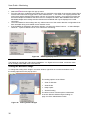
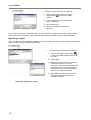
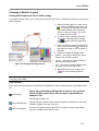
Saving the Monitored Image
You can save the current image from the monitor window to a file as a single-frame snapshot. Rightclick in the monitor window and select Save Frame As… from the pop-up menu, see Figure 63.
The captured image may appear upside-down or rotated to the left or right even if you have set the
camera mounting angle correctly in the camera properties. This is due to the fact that the camera
rotation is not taking into account when snapshots are captured.
Figure 63
Saving a Single Frame
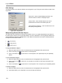
Use the browse window to navigate to the
directory where you wish to save the image
and enter a file name in the ‘File name:’ box.
Select the format in which to save the image
from the ‘Save as type:’ drop-down menu.
The list of types available depends on the type
of the camera.
Select Save to create and save the image file.
Figure 64
Creating a Snapshot File
Note: All camera snapshots can be saved in their original (native) format as long as RSM does not
have to perform any action on the file. There is one exeception to this rule: For a camera capable of
generating MPEG4 video, only the images passed as I frames within the MPEG4 stream can be
saved frame-accurately. The MPEG4 format, like the .eye (VL-10) format, can be read by RSM but
not interpolated.
All camera snapshots can be saved in BMP or re-encoded as JPG format if RSM has to perform an
action on the original image. Actions can be: Rotation; Dynamic Masking or Composing an image
from an I and (one or more) P-frames for a MPEG4 camera.
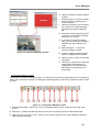
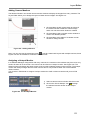
Loading a saved image
To load a saved image from a file to one of the monitor windows, right-click in the monitor window
and select Open Image From File…, see Figure 65.
38
User Guide - Monitoring
Figure 65
Loading a Snapshot File
Browse to find the file you wish to load, select it
from the list and select Open1..
P
P
The image is loaded into the target monitor
window in place of any existing image.
Figure 66
Loading a Saved Image
1.
All camera snapshots can be saved in their original (native) format as long as RealShot Manager
does not have to perform any further actions on the file.
P
P
There is one exeception to this rule: For a MPEG4 capable camer, images can only be saved in
MPEG4 format if the user wants to accurately save the I frame in an image stream. The MPEG4
format is only ‘readable’ by RSM, like the .eye (VL-10) format.
All camera snapshots can be saved in .BMP or re-encoded as .JPG format where RSM has to
perform some further action on the original image.
Actions can be:
1. Rotation
2. Dynamic Masking
3. Composing an image from a group of one I and (several) P-frames for a MPEG4 camera.
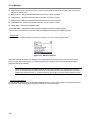
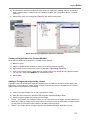
Changing Cameras in the Monitoring Layout
Selecting a Single Camera
To select a camera for viewing in a monitor window, right-click on a monitor and select the option
Select Camera…, see Figure 67.
39
User Guide - Monitoring
Figure 67
Select Single Camera
Select the camera you wish to monitor and
select OK to update the contents of the
monitor window.
Note: If the message
appears in the monitor window then the
RealShot Manager application is unable to set
up communication with the selected camera.
Check the status of the camera with your
System Administrator.
Administrators see also ‘Assigning a Single
Camera to a Camera Monitor’ on page 176.
Figure 68
Selecting Camera to Monitor
Selecting Multiple Cameras
You can use a single monitor to cycle through the outputs from several cameras. Right click on a
monitor and select the option Select Multiple Cameras…, see Figure 69.
Figure 69
40
Selecting Multiple Cameras to Monitor
User Guide - Monitoring
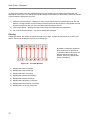
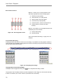
Build a list of cameras to share the monitor.
See Figure 70:
1) Select a camera or cameras. You can
select a block of cameras by using
SHIFT+LEFT MOUSE CLICK and a
discontinuous group of cameras by
using CTRL + LEFT MOUSE CLICK.
2) Add the selected camera(s) to the
monitor list by clicking on the button
marked
Figure 70
Multiple Camera Selector
.
Repeat steps 1) and 2) to build a list of the
cameras to be monitored.
You can now sort the active list so that the monitor cycles through the cameras in a specified order.
1) Select a camera and use the
button to move it to its desired position in the list.
2) Select a camera and use the
button to move it to its desired position in the list. Repeat steps
3) and 4) as necessary for all other listed cameras.
3) The image from each of the cameras selected will be displayed in turn in the monitor. To allocate
a duration to the display of each camera, select each camera from the right-hand list in turn and
enter the required duration in milliseconds in the box marked ‘Display Duration’.
4) To remove a camera from the list, select the unwanted camera from the active list and click on
the
button.
5) To save your changes select OK. The monitor window will scan through the listed cameras
displaying the output of each one for the specified duration.
6) To exit without saving your changes, select Cancel.
Administrators: see also ‘Assigning Multiple Cameras to a Camera Monitor’ on page 176.
41
User Guide - Monitoring
Assigning a Tour
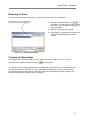
You can use a single monitor to cycle through a tour of preset positions for a single camera.
Select the monitor window and use the
‘Toggle Tours Toolbar’ icon to open the
‘Tours’ toolbar, see ‘The Tours Toolbar’ on
page 32.
Figure 71
Selecting a Tour
If any tours are specified for the camera
assigned to the selected monitor window then
one or more of the numeric buttons will be
highlighted. Select one of the highlighted
buttons or a named tour from the drop-down
list to view the images defined by the tour in
the selected monitor window.
You can also open the ‘Tours’ toolbar and
then select the camera directly from the
combo box. This enables you to build tours for
cameras not currently selected in a monitor.
For details of how to set up a tour, see ‘Building a Tour’ on page 46.
42
User Guide - Controlling Cameras
Controlling Cameras
Select the camera to be controlled in the monitoring window.
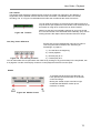
Using Pan/Tilt and Zoom (PTZ)
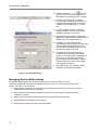
For a camera that is capable of PTZ functionality (e.g. the SNC-RZ30), you can use the ‘Pan& Tilt’
toolbar (see Figure 72) to control the camera image or you can use the mouse to go to a point in the
image or zoom to a defined area.
Control with the Pan & Tilt Toolbar
To open/close the Pan & Tilt toolbar, click
from the ‘View’ menu.
, on the main toolbar or select Pan & Tilt Toolbar
Summary of Controls:
•
The controls labelled 5 and 9 are for zooming the camera image in and out. See Figure 72.
•
Button 13 provides digital zoom and partial pan & tilt functionality for cameras that do not have
pan & tilt units and during playback of pre-recorded files.
Controls 2, 4, 10 & 12 allow a combination of the pan & tilt movements so allowing you to move the
camera’s field of view diagonally.
The remaining buttons allow you to pan the camera i.e. move it in the horizontal plane and tilt the
camera i.e. move it in the vertical plane.
1) The camera to be controlled is
identified by name in this box. You can
also click in this box to select a
different camera from the resulting
‘Select Camera’ window.
2) Pan left and tilt up
3) Tilt up
4) Pan right & tilt up
5) Zoom in
6) Pan left
7) Pan & tilt centre
8) Pan right
9) Zoom out
10) Pan left & tilt down
11) Tilt down
12) Pan right & tilt down
Figure 72
The ‘Pan & Tilt’ Toolbar
13) Toggle digital zoom
14) Wide Angle zoom
15) Telephoto zoom
43
User Guide - Controlling Cameras
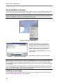
PTZ Using the Mouse
You can perform PTZ operations using the mouse on the image in a monitor window. This operation
matches the facilities provided by the Web browser utility available with the SNC-RZ30 camera.
1) PTZ to centre point
Select Ctrl + left-mouse click on a single point. The camera will reposition itself to centre the image
on the point that you have selected, see Figure 73.
Figure 73
PTZ to Centre Point
2) PTZ to a defined area
Select Ctrl + left-click with the mouse and drag the red box out to the area you wish to view, see
Figure 74. When you release the mouse, the camera will reposition itself to show the image within
the red box at the full size of the window.
Figure 74
PTZ to Area
3) Zooming in and Out
You can use CTRL+ Mouse Wheel to zoom in and out if you have a mouse with a scroll wheel.
44
User Guide - Controlling Cameras
Using a Joystick
If a Joystick such as the Microsoft Sidewinder has been configured as a control device, you can also
use this to control the camera PTZ settings. The exact configuration will depend on the model of
joystick used. See ‘General Settings’ on page 91 of the Administrator’s guide.
Using Camera Presets
Open/close the Pan & Tilt Presets toolbar, click
on the main toolbar. If a monitor window is
selected with an assigned camera then this camera is selected from the drop-down box. You can
also select the camera directly from the ‘Pan & Tilt Presets’ combo box.
Alternatively, select Preset Toolbar from the ‘View’ menu. You can control the camera to move to
any previously defined preset:
Figure 75
Selecting a Preset
Using Camera Presets
1) If you know the number of the preset you want to use, you can move the camera directly to
the saved position by clicking on the preset number, see Figure 75.
2) Only presets against which a camera position has been saved will be active, i.e. not greyed
out. If you need help identifying the preset you require, hover over the button and a tool-tip will
appear with the name of the preset.
3) You can open the presets list, select the ‘Customise Presets…’ icon
.
4) Alternatively, pull down the name list to display the available presets by name. Select an entry
from the list to move the camera to that position.
Select a camera from the drop-down list. To check a preset, use the arrow key to move the camera
to the selected preset - (9).
45
User Guide - Controlling Cameras
Creating a Preset
To create a new preset:
1) Select the ‘Customise Presets…’ icon
Figure 75.
to open the ‘Pan & Tilt Presets’ window as shown in
2) Move the camera to focus on the required view using the ‘Pan& Tilt’ controls (10).
3) Select a preset position from the numbered list. If the name field is empty enter the name
required for the new preset - (6).
4) To save the current camera position to the preset select ’+’.
Modifying an existing Preset
1) Move the camera to the selected preset position and select the arrow key (9), see Figure 75.
2) To modify the view, move the camera or zoom in/out using the ‘Pan& Tilt’ controls.
3) To update the name associated with the preset, edit the Name field.
4) To delete the position settings associated with the preset, select ‘-‘.
When you have finished creating or modifying the preset, select Close to remove this window and
save your changes. Note that you can select the camera image to save as a preset using the mouse
control facilities described in the section ‘PTZ Using the Mouse’ on page 44.
If you are controlling the SNC-Z20 it is only possible to modify existing presets, you cannot add new
presets or delete presets. See the SNC-Z20 User Guide for details of how to access the camera
presets for addition and/or deletion through the Camera Administrator application.
Building a Tour
You can use the presets previously specified as in ‘PTZ Using the Mouse’ on page 44 to build a
‘Tour’. The camera will move in turn to each of the preset PTZ positions in the tour and will hold that
position for the duration given.
1) Open the ‘Tours’ window by ensuring that the ‘Tours’ toolbar is visible and selecting the
‘Customise Tours…’ icon.
2) Select a camera from the drop-down list.
3) If starting a new tour, select ‘+’ and enter a tour name. To remove a tour, select the tour from the
list and select ‘-‘.
4) Move the camera to the required position either by using the controls, the mouse or the dropdown list of presets.
5) Preview the selected tour by selecting the right arrow.
6) Select ‘+’ in the Positions area and enter a name for the position. Set the duration to stay on this
image and the duration to take in moving to the next image.
7) To move the camera to the next or last position, use the right and left arrows.
8) To change the order of the presets in the list select one and then use the up and down arrows.
9) To remove a position select ‘-‘. To remove a tour select ‘-‘ from the ‘Tour Settings’ area.
10) Select OK to save your changes to the tours.
11) Select Cancel to exit without saving your changes.
46
User Guide - Controlling Cameras
Figure 76
Building a Preset ‘Tour’
Output control
Camera control outputs can be used to control devices such as electronic door locks or lights. To
trigger these outputs manually use the ‘Output Control’ toolbar having selected the associated
camera in the monitor window. For details of the connection and the signal levels see the manual
that accompanies the camera.
To show or hide the output control tools, click on the ‘Toggle Output Control Toolbar’ icon
main toolbar.
Figure 77
on the
Output Control Toolbar
For details of how to configure the camera outputs so that they can be triggered, administrators
should see the section ‘Assigning an I/O Box Pin to a Camera’ on page 144.
47
User Guide - Controlling Cameras
Recording
The RealShot Manager application allows you set up recording schedules of individual cameras and
groups of cameras. See ‘Scheduling Recordings’ on page 49.
Scheduled recordings can be triggered by activation of external sensors attached to cameras. This
‘alarm recording’ facility gives the ability to start recording on Activity Detection.
RealShot Manager also supports manually-triggered one-off recordings from the monitoring window.
You can take a snapshot from a monitored camera and store the resultant video frame as a still. You
can load previously saved snapshots in to a monitor window for viewing.
Manual Versus Scheduled Recording
Manual recording is started and stopped from the recording toolbar during monitoring. Scheduled
recording is set up from the Recording Schedule. See ‘Scheduling Recordings’ on page 49, and
allows you to create regular timed slots for monitoring, recording or alarm recording. Alarm recording
is where you set up a recording to be triggered by an external sensor connected to a camera.
Recording During Monitoring
With the recorder toolbar open, select a camera from the monitoring window.
1) If the Recorder toolbar is not visible then
click on the ‘Toggle Recorder Toolbar’
icon on the main toolbar to display it.
2) Select the number of frames per second
to record from the drop-down list.
3) Click on the ‘Record’ button to start
recording.
4) Click on the ‘Stop’ button to stop
recording.
Figure 78
Manual Recording
If you have not selected a monitor window
then a dialog will open with all the current
recordings listed. Select the recording(s) you
wish to stop.
5) Click on the snapshot button to take a
snapshot.
Taking a Snapshot
Browse to the directory where you wish to
save the snapshot, enter a file name in the
‘File name:’ box and then select Save to
create the image file.
Figure 79
48
Saving a Snapshot
User Guide - Controlling Cameras
Entering Comments During Recording
To enter comments during a manual recording use the comment toolbar, this can be opened or
closed by selecting the
button from the main toolbar. See Figure 80. Select this button again to
remove the comment toolbar.
Figure 80
Entering Comments
1) Comment area – Enter your comments here as text.
2) The Apply Comment button
allows you to register the comment and save it with a link to
clears the comment field in its entirety; if you
the camera. The Cancel Comment button
wish to delete just a few letters or words then the Delete key on your keyboard.
3) Shows the camera name to help identify the video file.
4) Marks the comment as:
High Importance
Normal Importance
Low Importance
Scheduling Recordings
The Schedule Editor
To open the Schedule Editor, click
on the main toolbar, which will display the current schedule
as illustrated by the example shown in Figure 81.
The Schedule Editor window is split into three panes:
1) A list of cameras, sorted into groups.
2) A Calendar of activities for the selected camera. (This view can be changed to a simple
activities list. See ‘Using the Week and List Views’ on page 51).
3) Event Details. For each event added to the schedule/list, selecting the event opens a form for
filling in details of the required activity. For details of the Recording Schedule toolbar, see ‘The
Schedule Editor Toolbar’ on page 29.
49
User Guide - Controlling Cameras
Note: By default every camera has an empty schedule. An existing schedule can be cleared to
create a new one. See ‘Clearing the Schedule’ on page 60.
Figure 81
The Schedule Editor Window
Selecting Cameras or Groups of Cameras
Grouping Cameras
To create a common schedule for a group of
cameras, select the group from the list in the
Schedule Editor. All the cameras in the group
are highlighted.
Any scheduled events you create in the
schedule or list view while the group is selected
will now be applied to all the cameras in the
group.
Administrators see ‘Managing Groups’ on page
134 for details of how to create a group of
cameras and other devices.
Note that groups can be nested i.e. there can be
sub-groups within a group. You can select a
group at any level.
Figure 82
50
Selecting a Group
User Guide - Controlling Cameras
To create a schedule of monitoring and
recording activities for a single camera, expand
the ‘Cameras’ group by selecting the + sign next
to it and then select the required camera. You
can also select a single camera from the lowest
level of the ‘Groups’ tree.
Figure 83
Selecting a single Camera
Using the Week and List Views
The ‘Week’ and ‘List’ views show the same event information in different formats.
The ‘Week’ view shows a weekly calendar of colourcoded bookings for the selected camera.
Switch to the ‘List’ view using the ‘View As List’ button
on the Schedule Editor toolbar
.
The ‘List’ view is a summary of all the actions
associated with the selected camera.
Return to the ‘Week’ view using the ‘View as Week’
button on the Recording Schedule toolbar
.
Display or hide the event details form by selecting the
Figure 84
Schedule Views
‘Toggle Form’ button
toolbar.
on the Schedule Editor
51
User Guide - Controlling Cameras
Each scheduled event is shown as a single entry in the ‘List’ View:
Figure 85
Example Schedule Event Entries
From left-to-right the columns are as follows:
1) Type of event: Recurring
or Date/Time
.
2) Event Name
3) Type of Event
Icon
Activity
Monitoring
Normal Recording
Alarm Recording (Note: Motion
Detection can raise an alarm to
trigger recording).
Pre/Post Alarm Recording
Retail Mode Recording
Cleanup Job
Table 1: Event Activity Icons
4) Start – Start time for recurring events is hh:mm:ss and for date/time events dd mmm yyyy hh:mm:ss.
5) End – End time for recurring events is hh:mm:ss and for date/time events dd mmm yyyy hh:mm:ss.
6) Duration – The duration of the activity in hours, minutes, seconds or hh:mm:ss.
7) Weekdays – A mask of seven codes to specify on which days of the week the activity takes place. ‘_’
is equivalent to not active on that day of the week.
Position 1
Position 2
Position 3
Position 4
Position 5
Position 6
Position 7
M= Monday
T = Tuesday
W= Wednesday
T= Thursday
F=Friday
S=Saturday
S=Sunday
52
User Guide - Controlling Cameras
Events and Types
Colour-Coding and Priorities
Activities within the weekly view of the schedule are colour coded according to the chart below. The range
of event types available depends on the RealShot Manager configuration. For example, the ‘Retail’ event
type is only available if RealShot Manager is configured to work with a Retail module.
Figure 86
Event Colour-Coding
The type of event or activity is chosen using the check
boxes within the camera activity form. You can select
multiple activities to happen simultaneously by
checking multiple boxes.
External sensors such as motion-sensors, contactclosures for doors and windows and the I/O pins of a
BarioNet audio device may be connected to the Sony
range of surveillance cameras to trigger recording
based on an alarm being raised.
Figure 87
Event Types
If you select Alarm recording, the Pre-Alarm check box
is also enabled.
If activities overlap then the highest priority activity takes precedence. Alarm recording can be used to
increase the quality of the image when an alarm occurs during normal recording. Assuming that the
parameters for the alarm recording are for a higher quality picture than the normal recording, the effective
priorities are as follows:
1) Alarm Recording
2) Normal Recording
3) Monitoring
As an example, if you want to record at 10 frames per second (fps) as Normal Recording, for the whole
day and increase the frame rate to 25 fps only when there is an active alarm as Alarm Recording:
Set the monitoring frame rate for display purposes to 10 fps (Monitoring). This will result in retrieving
monitor images from the camera at 10 fps when there is no alarm. When there is an alarm, the frames will
be retrieved at the highest of the overlapping frame rates i.e. 25fps.
Note: You can also set the frame rate independently for recordings to be different to the monitored frame
rate. For example, you may wish to monitor a camera at 20fps but only record 5fps.
If you set the Normal Record activity to a resolution of 320x288 and the Monitor activity resolution to
720x576 the image retrieved from the camera will be 720x576. So the maximum values for the frame rate
and resolution from all current activities are always used.
53
User Guide - Controlling Cameras
Retail Events
RealShot Manager can be integrated with an external retail module for gathering data on customer
movements. If the retail module has been enabled it will be possible to add retail events to the timed
schedule to gather retail data. These events are colour-coded according to the scheme shown in
Figure 86. For details of how to configure the retail module, see the section ‘External Module
Integration‘ on page 99.
Retail events are a special case and must be added using the dedicated toolbar buttons see Figure
88.
1) Add timed Retail event.
2) Add recurring Retail event.
Figure 88
Retail Event Buttons
Cleanup Events
Cleanup events purge stored recordings associated with the selected camera(s):
Cleanup events are added using
the toolbar buttons:
1) Add timed Cleanup event.
2) Add recurring Cleanup
event.
Figure 89
Cleanup Event Buttons
The recordings held by the
selected cameras are purged
according to the cleanup job
parameters.
Highlight the Cleanup job in the list
or week view to set or modify the
parameters. See Figure 90.
54
User Guide - Controlling Cameras
Start/End Time and Duration Specify the period over which the
cleanup will happen.
Note: Please ensure that the Start
and End times are different i.e. that
the resultant Duration of the
cleanup event is not zero.
Manual/Normal/Alarm - check the
types of recordings to be be
purged
Cleanup files older than –
minimum age in days of the
recordings to be purged
Figure 90
Date/Time Cleanup Parameters
Note: The ‘Weekdays’ check boxes are used to specify
which days of the week the purge is to take place. See
Figure 91. The Cleanup Job will start at the allocated ’Start
Time’ and is not repeated.
Cleanup All Files - when this is
checked, all files found of the
specified type(s) will be deleted
regardless of the age and capacity
settings.
Cleanup options
Delete – Files meeting the cleanup
criteria are deleted permanently.
Archive – Files are moved to the
associated archive system and
may be recovered at a later date.
Check remaining disk capacity –
enables or disables checking the
disk capacity of the storage
‘If capacity is less than’ - when the
capacity is lower than a certain
percentage or specified number of
MBytes, you can modify the
minimum file age. Use the dropdown list to choose between a
percentage or MByte threshold.
Use the ‘Then clean up files older
than:’ box to enter the modified
minimum file age.
55
User Guide - Controlling Cameras
Figure 91
Inserting a Recurring Cleanup Job
In a recurrent cleanup job, see Figure 91, the ‘Weekdays’ check boxes are used to specify on which
days of the week the cleanup job is to run. The remaining event parameters are the same as for a
Date/Time cleanup job, see Figure 90. The Cleanup job starts at the allocated start time and
completes automatically. It is not repeated. The notional duration is only to warn other users that this
period is reserved for housekeeping activities.
One example of the consequences of the fact that cleanup events are edge-triggered is as follows:
If you schedule a cleanup job to last from 00:00:00 until 23:59:59 it will only trigger once, and once
only, at 00:00, it has the same effect as scheduling from 00:00 till 00:01. You cannot schedule a
cleanup job that will allow cleanup jobs to run all the time by scheduling one event every day lasting
from 00:00:00 till 23:59:59 (i.e no gap in the schedule). The result of this attempt to set ’24 hour
scheduling of cleanup jobs’ will be that a cleanup job will be run once only each day at the start time
of the event.
Motion Detection Events
Motion Detection (MD) is a different kind of activity detection and is implemented in a similar way
using I/O ‘pins’. However, Activity Detection (AD) is performed by the camera and Motion Detection
is processed in software by RealShot Manager. This results in a difference between MD and AD pins.
MD pins can be switched on and off with a certain configuration following a certain schedule.
The scheduling facility makes it possible to change the area where motion detection is performed at
different times. The schedule is created by selecting different motion detection configurations, each
configuration has an associated camera preset and one or more motion detection areas.
56
User Guide - Controlling Cameras
MD events can trigger alarm recordings if the MD pin is selected as input pin for the alarm recording.
MD schedule items can be recognised by their orange colour with an icon like a little running human
being inside.
Monitoring and normal recording is also available when scheduling an MD event, this allows the
scheduling of a MD event that is modified to request a lower frame-rate by also selecting the
monitoring tab and specifying a lower frame rate (fps), this saves processing power and is useful as
MD is very CPU intensive. The same logic is true for normal recording but the lower frame-rate
specified in this tab is also recorded with the resulting MD metadata and stored in the CAM file and
thus the motion detection areas can be shown on playback (the green boxes that indicate
movement).
Motion detection events specify the period over which RealShot Manager will detect moving objects.
Use the dedicated menu icons to add a recurring or date/time Motion Detection event, see ‘Adding a
Motion Detection Event’ on page 59.
This event will appear in the schedule for the selected camera. The duration, start/stop times and
frequency can be modified in the same way as for an Alarm Recording event, see ‘Modifying
Activities’ on page 60.
Details of how to configure the areas for motion detection are given in the section ‘Motion Detection’
on page 123 and the Motion Detection Event parameters are explained in ‘Motion Detection Event
Parameters’ on page 63.
Building a Schedule
Explaining the Schedule
The Weekly Schedule is a view of the events scheduled to occur every week, see Figure 92. Only
events that happen on specific dates are shown in the List view.
Figure 92
The Weekly Schedule View
The simplified example schedule shown above is made up of four individual activities:
1) A Normal Recording activity between midnight and 9:00 Monday through Saturday.
2) An Alarm Recording Activity between 12:00 and 14:00 Monday through Saturday. Note that
you do not know without looking at the associated form whether the camera is being
monitored during this period, background monitoring does not affect the colour of the activity.
3) Monitoring only between18.00 and 20.45 Monday through Saturday.
4) Simultaneous recording and Alarm Recording between midnight on Saturday and 20.45 on
Sunday.
57
User Guide - Controlling Cameras
The schedule grid is graduated in periods of 15 minutes. Activities can be manipulated by dragging
the start or end of the event to a new time. You can also adjust the start and end time by modifying
the form on the bottom-right of the screen if you want to start recording at any time interval that does
not fall on a 15-minute boundary.
The event type is illustrated within each activity by the same icons as shown in Table 1.
Adding Recurring Activities
The following steps describe the example of adding a scheduled Monitoring activity see Figure 93:
1) Select a camera or group of cameras for which you wish to create a new scheduled event.
2) Click on the ‘Insert Recurrent Item’ icon
on the Recording Schedule toolbar to insert the new
activity into the Week View. This will not reset the values in the form so the new activity will start
out as a copy of the previously edited one.
3) Select the days of the week on which the activity is to take place using the weekday check boxes.
See Figure 93 (1).
4) Enter an event name
5) Enter a Daily Start Time and End Time or Duration.
6) Select the required combination of activity types using the check boxes; in this case Monitoring
only is selected. See Figure 93 (2).
7) Select the required quality parameters for the monitor image. See Figure 93 (3). For further
details of the parameters see ‘Recording image quality’ on page 61.
Figure 93
Details of a Monitoring Event
Adding Timed Activity
Select a camera or group of cameras and click on the
open the related schedule in the list view.
58
button on the Schedule Editor toolbar to
User Guide - Controlling Cameras
1) Enter the details of the required event
into the form as for a recurrent item but
instead of setting the days of the week:
2) Enter a name for the event.
3) Set the ‘Start Date’ and Time and the
‘End Date’ and Time.
Figure 94
A Timed Activity
Select the
button from the Schedule Editor
toolbar to insert these details as an item in the
event list.
The resultant entry in the list will have a duration calculated from the Start and End and will be
marked with the calendar icon
to show that it is a date/time event.
Figure 95
Timed Activity Details
For further details see ‘Using the Week and List Views ’ on page 51.
Adding a Motion Detection Event
To add a recurring Motion Detection (MD) Event, select the ‘Insert Recurrent Motion Detection Item’
icon from the Schedule Editor toolbar, see Figure 96. To add a date/time Motion Detection Event,
select the ‘Insert Date/Time Motion Detection Item’ icon from the Schedule Editor toolbar, see Figure
97.
Figure 96
Adding Recurring MD Item
Figure 97
Adding Date/Time MD Item
Motion Detection Event parameters are explained in ‘Motion Detection Event Parameters’ on page
63.
Removing Activities
The procedure for deleting a scheduled event is the same from either of the two views:
59
User Guide - Controlling Cameras
Select the event you wish to remove and then select
, or press the <DEL> key.
Clearing the Schedule
To completely clear the schedule associated with the selected camera or camera group, click on the
‘New Schedule’ button on the Recording Schedule toolbar
.
You will be asked to confirm this action with the message ‘Are you sure you want to start with an
empty schedule for the selected camera(s)?’. Answer Yes to clear the schedule and No to leave the
schedule intact.
Modifying Activities
To modify an activity, select the entry in either the Week View or List View and make the changes
required in the activity form.
To save the changes, select the icon
on the Recording Schedule toolbar.
If you make changes to the schedule and try to select another camera or leave the Recording
Schedule window, you will be prompted with the following message:
Figure 98
Schedule Change Confirmation Dialog
Select Yes to save your modifications, No to abandon them and Cancel to continue editing this
camera’s schedule.
You can relocate activities within the same day
of the weekly calendar view by dragging the
whole activity to the new required time.
Figure 99
Moving an Event
To trim an event in the weekly calendar view,
you can drag the start or end of the activity to a
new time.
Figure 100 Trimming an Event
60
User Guide - Controlling Cameras
Monitoring Activity Parameters
Monitor Image Quality
The parameters for a monitoring activity all relate to the quality of the image to be displayed.
Ensure that the ‘Monitoring’ check box is
enabled.
For a description of the values allowed in each
field. See the Administrator’s guide section ‘
Figure 101 Monitoring Parameters
Setting Camera Properties’ on page 121.
Normal Recording Parameters
Recording image quality
The parameters for a normal recording activity all relate to the quality of the image to be recorded.
Ensure the ‘Normal Recording’ check box is
selected.
For a description of the values allowed in each
field. See the Administrator’s guide section ‘
Figure 102 Recording Parameters
Setting Camera Properties’ on page 121.
Alarm Recording Parameters
Alarms can be triggered based on changes in the state of camera input pins Note that the tabs for
entering Alarm and Pin details only appear when the ‘Alarm Recording’ check box has been enabled:
Alarm Image Quality
The parameters for an alarm recording activity all relate to the quality of the image to be recorded.
Alarms are triggered when a camera sensor is activated. See the Administrator’s guide section
‘Adding Pin Details’ on page 143.
Ensure the ‘Alarm Recording’ check box is
selected.
For a description of the values allowed in each
field. See ‘
Figure 103 Alarm Parameters
Setting Camera Properties’ on page 121.
61
User Guide - Controlling Cameras
In typical use, the quality of the image required from an alarm recording should be better than that
required during a normal recording. This is to ensure that the images collected following an alarm
are clear enough to identify the cause of the alarm.
Selecting Camera Pins
Each input pin from a camera can be selected to trigger an alarm recording or monitoring. Selecting
multiple pins results in ‘OR’ functionality. The alarm recording is triggered if any of the selected pins
changes state.
Enable the check box beside the input
pins that should trigger the alarm
recording or monitoring activity.
Figure 104 Input Selection
Pre and Post Alarm Parameters
The pre-alarm and post-alarm parameters for an alarm recording activity relate to the duration of the
recording to be triggered by an alarm.
Ensure the ‘Alarm Recording’ and ‘Pre-Alarm’ check boxes are both selected.
Figure 105 Pre and Post Alarm Parameters
•
The pre-alarm frames per second (‘Frames/second’) allows you to capture the images recorded
during the moments immediately before an alarm. See Figure 105.
•
The ‘Pre Duration’ is the period of time prior to an alarm for which images should always be
cached. These cached images will have the quality and fps setting of the associated alarm
recording.
•
When an alarm occurs these images are saved to a file with the fps specified in this tab.
•
When an alarm has occurred, the time for which recording is maintained after the alarm is set in
‘Duration field’.
•
If ‘Post Alarm’ is selected then the recording stops n seconds (Duration) after the alarm
condition is cleared; this means that the total duration recorded is duration of alarm + Duration.
•
If Fixed Duration is selected then recording continues for the period specified by the Duration
field regardless of whether the alarm is cleared during this time.
The diagram shown in Figure 106 illustrates the relationships between the different time parameters:
62
User Guide - Controlling Cameras
1) ‘Pre Duration’ – Images are cached for
this duration regardless of whether an
alarm is activated. They are saved when
an alarm is activated.
2) ‘Alarm Duration’ – The alarm signal is
active for this period.
3) (Post Alarm) ‘Duration’ – If the Duration
field is set with Post Alarm selected then
recording continues for this number of
seconds after the alarm is cleared.
4) Alarm recording starts at the point the
alarm is raised.
Figure 106 Alarm Timings
5) If Fixed Duration is selected then
recording continues for the number of
seconds in the Duration field regardless of
whether the alarm is cleared during this
time.
To trigger an output, select the output from those available (highlighted), in the range A-H. For
instructions on how to set up the camera outputs; see ‘Assigning an I/O Box Pin to a Camera’ on
page 144.
Motion Detection Event Parameters
Configuration
The configuration drop-down list on the ‘Motion Detection’ tab, see Figure 107, allows you to specify
the area of interest for motion detection over the specified period. Details of how to configure the
areas for motion detection are given in the section ‘Motion Detection’ on page 123.
Figure 107 Motion Detection Event Parameters
Inputs
From the Inputs tab you can select the motion detection pin to trigger the alarm recording associated
with the detection of motion in the configured area. Details of how to configure the areas for motion
detection are given in the section ‘Motion Detection’ on page 123.
Normally you will select the pin associated with the camera in whose schedule this alarm recording
event appears. However, if the Motion Detection IO-Box has been configured to allow selection of
another camera’s pin it may be possible to start a recording from a different camera. You may wish
to do this if the first camera is monitoring an entrance but a second camera is monitoring something
valuable such as a painting in the room.
63
User Guide - Playback
Figure 108 Selecting a Motion Detection Input
Copying and Pasting Schedules
To use a schedule set up for one camera/group for a second camera/group, use Copy and Paste on
the Recording Schedule toolbar to duplicate the schedule. See ‘Selecting Cameras or Groups of
Cameras’ on page 50.
1) With the first camera/group selected, click on the ‘Copy Schedule’ icon
2) With the second camera/group selected, click on the ‘Paste Schedule’ icon
.
.
Playback
You can load any previous recording into a monitor window and play it back to review the images
captured.
Searching for Recordings
To search for a previously recorded file to view, select the ‘Search Recording’ button from the main
toolbar or the ‘Search…’ button from the Playback toolbar. Both of these are represented by the
.
image of a pair of binoculars
64
User Guide - Playback
Selecting the Camera(s)
Figure 109 Search Recording - List View
1) To perform a search based on the camera that sourced the recording, select the camera from
the camera list. You can add cameras individually to the search by holding down the ‘Shift’ or
‘Ctrl’ key whilst selecting the additional cameras with the left mouse button.
2) To refine the search based on a date/time period use the calendar facilities provided on the
Search Toolbar. See ‘Searching Based on Date/Time’ on page 65.
3) The recordings selected are displayed in one of two views; the Recording List and the
Recording Timeline. Figure 109 shows the results as a Recording List. See ‘Using the
Timeline View’ on page 67. You can double-click on an entry in either view to open the
associated video file in the current playback monitor.
4) Any Comments associated with the recordings are listed separately below the files. See ‘The
Comment Toolbar’ on page 33.
5) The file can also be represented by picture stamps. See ‘Picture Stamps’ on page 69.
The search results do not automatically refresh if new recordings are being created, select the
‘Refresh Recordings’ icon
from the ‘Search Recording’ toolbar to update the file list.
Searching Based on Date/Time
Using the calendar controls on the ‘Search Recording’ toolbar you can zoom in and out to focus on a
particular period in time and you can scan forward or backward in time for related recordings.
65
User Guide - Playback
Zooming the Timeframe In and Out
to focus in on a smaller timeframe. For
Use
example:
Year : 2003 to
Month : February 2003 to
Week : Week 6 February 2003 (from 1st Jan) to
P
P
Day : Wednesday 12th Feb 2003 to
P
Figure 110 Zooming
P
Time : 12 Feb 2003 13.31
Fine Time: 12 Feb 2003 13.31:19 (including
seconds).
The above example is based on a European
date format of dd/mm/yy; i.e. dd: date,
mm: month, yy: year. The date format may vary
from those described above if the local date/time
format is different, e.g. the American date format
is mm/dd/yy and the Japanese date format is
yy/mm/dd.
Use
to widen the focus again to increase the
range of recordings displayed.
Specifying the Date/Time Range
If the date you require is not recent then you can
use the full calendar to find it. Click anywhere in
the date box to open the calendar.
Select the date and/or time you require and
select OK.
To select the next time interval select
To select the previous time interval select
The interval forward or backward is the same as
that displayed i.e. by one month if a month is
displayed.
Figure 111 Using the Calendar
66
The range of recordings selected will be
displayed in the list or on the timeline.
User Guide - Playback
To select the next time interval select
. The
interval advanced is the same as that displayed
e.g. by one week if a week is displayed.
Figure 112 Moving in Time
To select the previous time interval select
.
The interval retarded is the same as the level
displayed e.g. by one hour if a time is displayed
to the nearest hour.
Using the Timeline View
You can toggle between the list and timeline views in the Search Recording window by selecting the
and
icons on the ‘Search Recording’ toolbar, see Figure 113.
Recorded events on the timeline are colour-coded in the same way as scheduled recordings in the
Recording Schedule. See ‘Colour-Coding and Priorities’ on page 53.
You can double-click on any recorded event to open the video file in the currently selected monitor
window.
Recordings are automatically purged according to the criteria entered in the Cleanup tab of the
General Settings. See ‘Alarm Settings‘ on page 95.
In either view, the Comment window will show all comments associated with visible recordings.
67
User Guide - Playback
Figure 113 Search Recording Views
If a large number of cameras are selected, the timeline view may become crowded. Focus your
search on a small number of cameras to improve readability. For instructions on how to select and
deselect cameras see ‘Selecting the Camera(s)’ on page 65.
The red line (walker) represents the current time, see Figure 114. When you zoom in its position will
be used as the current time around which to center the zoom. If you are viewing a week and you
.
drag the walker to Monday you will zoom in to this day when pressing
Left double-clicking on the header bar performs a zoom in and right. Right double-clicking performs a
zoom out.
The walker gives you an indication of where you are in the timeline, e.g. when you are in a week
view and the current time is 10:00 on Monday, the walker will be positioned toward the left. If you
zoom in, the Monday will be shown in detail and the walker will stay at 10:00, which results in it
jumping to the far right.
68
User Guide - Playback
Figure 114 Zooming in on the Timeline
Modifying the Search Window
Picture Stamps
For each file recorded, the RealShot Manager application generates one or more picture stamps to represent
the file in a storyboard view.
Figure 115 Storyboard
69
User Guide - Playback
An area of the Search Recording window displays the storyboard of picture stamps associated with the
selected file. See Figure 115. Use the three picture stamp control buttons on the toolbar to select the number
of picture stamps displayed in this area.
1) ‘Maximum Picture Stamps’ – Displays as many picture stamps from the selected file as will fit in the
window. If a large number of picture stamps are associated with this file then the storyboard area will
provide scroll bars so that you can move backward and forward in the list.
2) ‘One Picture Stamp’ – Displays the first picture stamp associated with the selected file.
3) ‘Do not show Picture Stamps’ – No picture stamps are displayed.
Filtering
Following a search, the number of results returned may be high. The filter buttons allow you to refine your
search. The list can be filtered on priority or recording type:
By default no filters are applied so
all of the buttons are pressed-in.
To activate a filter and remove the
affected entries from the list or
timeline, click on the appropriate
button to deselect it.
Figure 116 The Filter Buttons
1) Display/Hide video recordings
2) Display/Hide audio recordings
3) Display/Hide alarm recordings.
4) Display/Hide scheduled recordings
5) Display/Hide manual recordings
6) Display/Hide High priority comments.
7) Display/Hide Normal priority comments.
8) Display/Hide Low priority comments.
70
User Guide - Playback
Browsing for Files
You can select recordings to play back by accessing the video files using the Browser.
from
1) Select the ‘Open Recording’ icon
the toolbar. This will open a browse window
from which you can locate the video file you
wish to play back.
2) Select the video file to be opened.
3) Select Open. The video file is opened in the
currently selected playback window for
viewing.
Figure 117 The Browse Window
Cleaning Up Recordings
Recordings can be deleted manually from the ‘Search Recording’ window. Select one or more
recordings from a search results list and then
from the toolbar.
As a further insurance against disks becoming full individual purge events can be scheduled for files
recorded from particular cameras. You can create regular schedule jobs to perform automatic file
purging and set ageing criteria for files. Recordings are then automatically purged according to the
cleanup schedule. See ‘Cleanup Events’ on page 54.
71
User Guide - Playback
1) Select the ‘Cleanup…’ icon
. This will
open a window in which you can set the
parameters for cleaning up old recordings.
2) To restrict the cleanup to only those
cameras and/or audio devices selected in
the Search Recording window, select the
‘Cleanup selected device(s) only’ check
box.
3) To purge all disks based on remaining
capacity enable the ‘Cleanup when disk
capacity is less than:’ check-box.
4) Select either a percentage or MegaBytes
(MB) from the right-hand drop-down list and
enter a number in the left-hand box.
5) In addition, you can purge old files
automatically. Enter a number of days in the
‘Cleanup all recordings older than:’ box.
This will delete recordings even when the
checkbox in 3) above is not set.
6) To Delete all recordings matching the
criteria permanently, select the ‘Delete’
option. If your RSM system is interfaced to
an archive you can select the ‘Archive’
option instead. Files meeting the cleanup
criteria will be sent to the archive system
and can later be restored.
7) Select OK to save your settings. Select
Cancel to exit without saving them.
Figure 118 Cleanup Settings
Managing Archived Recordings
Recordings that have been sent to an archive system can be recovered at any time.
Select a recording from the search results and use one of the icons on the archive section of the
toolbar, see Figure 119, as follows:
1) Select ‘Restore Recording’ to mark this item for retrieval from the archive. A local copy will be
created that can be used for previewing.
2) Select ‘Unrestore Recording’ to delete the local copy of an archived recording previously
created by a restore.
3) Select ‘Archive Job List’ to view a list of the currently active archive activities.
4) Select Refresh to update the archive job list.
5) Select Close to remove the archive job list window.
72
User Guide - Playback
Figure 119 Restoring from Archive
Previewing a Recording
Perform a search to locate the recording you wish to preview (see ‘Searching for Recordings’ on
page 64), select a recording from the search results list and then select the ‘Preview Selected
Recording’ icon from the toolbar
.
The ‘Playback Recording’ toolbar is displayed and the first frame of the file is cued in the preview
window that is opened in the bottom right pane of the ‘Search Recording’ window.
73
User Guide - Playback
Figure 120 Controls for playing back a Recording
The Playback Controls
The controls available for controlling playback of a recording are shown in Figure 121. For a full
description of how to use these controls, see the following sections:
•
•
•
•
•
•
The Timeline on page 75
Cue, Play, Pause & ReverseShuttle on page 75
Fast Forward, Reverse on page 76
Previous/Next Recording on page 76
Timelapse Mode Versus Normal Mode on page 76
Exporting to an AVI File on page 77.
RealShot Manager can play back the audio associated with a recording if it is available, see
‘Searching for Recordings’ on page 64. The creation of audio files requires correct associations to be
set up between and audio device and a camera at the time of recording. To hear the audio from an
audio device associated with a camera when monitoring ‘live’, see ‘Monitoring Audio’ on page 79.
Figure 121 Playback Recording Controls Toolbar
Use the playback controls to view the file. If you wish to highlight part of the file, use the Mark In
and Mark Out
74
buttons to set a start and end point of interest.
User Guide - Playback
The Timeline
The timeline area displays the date and time at which the image was captured. It also displays a
single letter code to indicate if the file was the result of an alarm, a scheduled event or a manual
recording. The ‘A’ in Figure 122 indicates that this file was recorded as the result of an alarm.
You can drag the red line to move through the video quickly but it
may be hard to spot a particular event as the scroll movement is not
as smooth as using other controls such as ‘Slow Forward’.
Figure 122 Timeline
Notice how the time in this display changes as you move the red
line. The last number in this time field will occasionally ‘jump’ due to
missing frames if the capture frame rate was lower than 25 fps.
Cue, Play, Pause & Reverse
Ensure that you have selected the video file you want to
view using the search facilities; see ‘Searching for
Recordings’ on page 64.
1) Cue the file to the beginning.
2) Pause playback
3) Reverse play at x1.
Figure 123 Cue and Play Controls
4) Forward play at x1.
You can also select the cue point within the video file by clicking on any picture stamp in the storyboard, see
0 on page 69. Use the cue and play controls to control playback of the file from this point.
Shuttle
To navigate quickly through the video file you
have opened, left click and hold on the shuttle
control and drag it.
Moving the shuttle control to the left or right
accelerates the REW/FF further up to a
maximum of 1000%.
Figure 124 Shuttle Control
75
User Guide - Playback
Fast Forward, Reverse
Buttons 1-6 allow you to control playback of the
video file at speeds other than the play speed.
1) ‘Rewind’ (x-5 play speed)
2) ‘Slow Reverse’ (x-0.2 play speed)
3) ‘Slow Forward’ (x0.2 play speed)
4) ‘Fast Forward’ (x5 play speed)
5) ‘Frame Reverse’ (moves one frame back)
6) ‘Frame Advance’ (moves one frame
forward).
Buttons 7 and 8 allow you to navigate between files
recorded by the same camera.
Figure 125 Non Playspeed Control
7) ‘Previous Recording’
8) ‘Next Recording’
See ‘Previous/Next Recording’ on page 76 for an
example.
Previous/Next Recording
Following a search that returns more than one recording, it is possible to use the playback toolbar to
move forwards and backwards opening files from the list of recordings using the Previous Recording
and Next Recording toolbar buttons:
Figure 126 Navigating Recordings
Timelapse Mode Versus Normal Mode
Timelapse mode is toggled on/off by using
on the ‘Playback Recording’ Toolbar.
The purpose of the Timelapse mode is to make the playback of the images in a file smooth and easy
to follow. This allows you to check a file for a particular event more easily.
76
User Guide - Playback
Timelapse mode imposes a fixed frame-rate on the replayed images. If the images were recorded at
a low frame-rate, e.g. 1 frame every three seconds then the Timelapse mode replay frame-rate will
be higher and so easier to see.
Tip: To see Timelapse mode obviously in action, make a recording with a very low frame-rate (e.g.
Interval = 5000 ms or 0.2 fps), i.e. ensure that the recording lasts at least 15-30 minutes .
Play the file back with Normal play and you will see very little activity. Next, play the file back in
Timelapse mode. The images should play back very smoothly and it will be easy to check the
content.
Select View > Date/Time in the monitor from the right-click pop-up menu to see the actual time of
recording for a playback.
In 'Normal mode' the fixed frame-rate is set to 10 images per second. This number is chosen, so that
the human eye can easily track each image. If a higher frame-rate were chosen, e.g. 25 images per
second then the eye cannot easily distinguish each individual frame.
Worked Example:
As an example, if you have recorded a file at 1 image every 3 seconds and then you play the file
back using Normal Play you will see the image at 30x the normal speed. If you replay with Slow
Forward, you will see 2 images per second, i.e. 6x normal speed. Fast-Forward is 5x Normal play
speed, so in this case, 50 images per second and thus 150x the capture speed. For other speeds,
the shuttle slider can again be used. Timelapse mode with its fixed 10 images per second will give
the smoothest and easiest playback to follow.
Exporting to an AVI File
To export a recorded file to the ‘AVI’ format, use the following procedure:
1) Select the ‘Export to AVI File’
icon from the ‘Search Recordings’ toolbar.
2) Set the image parameters for the AVI file to be created.
3) Click on Settings… to modify the codec setup
4) Select OK to save the codec settings. The actual settings displayed will depend on the codec
used and may appear rather different to those shown in Figure 127.
5) Use Browse… to select the output file.
6) Select Save to confirm the output file.
7) Select the ‘Show all available codecs’ check-box to provide your widest choice of codecs.
8) Select Yes in the warning dialog to confirm the codec request.
9) Select Export to start the conversion.
10) Watch the progress bar to monitor the conversion.
11) Select Close when the conversion has completed.
77
User Guide - Playback
Figure 127 Exporting to an AVI File
Deleting Comments
You can remove comments using the ‘Search Recording’ window toolbar. Select a comment from the
list available and then
78
.
User Guide - Playback
Monitoring Audio
The audio toolbar allows you to control the monitoring of the audio. The audio toolbar controls are as
follows
1) The ‘Link Audio to Camera’ button allows you to make a link between an audio device and the
camera selected in a monitor window. When this button is disabled, the drop down list allows you
to select the source of the audio you wish to monitor from the list of available audio sources.
2) The ‘Toggle Audio’ mutes the audio, when enabled, regardless of whether there is an active
audio link.
Figure 128 Audio Toolbar Controls
When the camera/audio linking button is depressed, only audio sources that have been associated
with a camera can be monitored. This association is created in the Setup manager, see ‘Managing
Audio Devices’ on page 147. To monitor the audio, an audio decoder must be installed. An audio
decoder is available to be installed from the installation disc if required, but not installed by default. If
you are unsure about this, consult your administrator.
79
User Guide - Playback
Monitoring Alarms
The Alarm Monitoring icon on the main toolbar allows you to monitor alarm inputs either within the
main application window or from a separate alarm window:
Figure 129 The Alarm Monitoring Window
1) Open the alarm window by selecting the Alarm Window icon from the main toolbar.
2) To undock the alarm window as part of the main window, drag it by the title bar away from the
edge of the main window and it will become detached to form a separate window. To dock it
again, reverse the procedure.
Alarms are configured through the Setup Manager, see ‘Managing I/O Boxes’ on page 141 and the
General Settings window, see ‘Alarm Settings’ on page 95.
80
Configuring RealShot Manager
Administrator Guide
Configuring RealShot Manager
Types of Configuration
Cameras can be shared between different RealShot Manager PC's that are connected to each other via an
Ethernet network. This sharing functionality is known as ‘Multi PC’ and can be used to establish complex
configurations, for example:
•
Server-Client
•
Remote Monitoring
•
Combinations of Server-Client and Remote Monitoring
Server – Client
The user monitors cameras and sets up schedules from the RealShot Manager the client PC. Any video
recorded manually or as a result of a scheduled recording is typically stored on the server PC (although it
may be stored in the Client PC if a valid storage location has been defined and mapped on the Client).
Client and Server can coexist on the same PC or a separate server PC can be installed with no GUI client
application, see Figure 130. This configuration is useful if the video recorded by the cameras needs to be
accessible from more than one place. For example, different security offices are responsible for surveillance
at different times during the week.
Figure 130 Server-Client Multi-PC Configuration
Remote Monitoring
An operator can monitor cameras and view previous recordings at either the Remote Monitoring PC or the
Local Recording and Monitoring PC. See Figure 131. This configuration is useful if multiple sites are
monitored from a central location during off-peak hours. For example if a local council security department is
responsible for security at all leisure facilities in a town during the night.
81
Scaling/Tuning a System
Complex Multiple-PC Configurations
Combinations of Server-Client relationships and Remote Monitoring configurations can be used to design a
complex and flexible security solution. The administrative tools described in this guide support the setup and
modification of your RealShot Manager solution so that it continues to support your needs even if they
change throughout the life of your organisation.
T
Figure 131 Remote Monitoring Multi-PC Configuration
Scaling/Tuning a System
When designing or modifying a RealShot Manager monitoring system, there are many possible
configurations. The process of scaling/tuning the system is that of deciding how to distribute the required
cameras, set up the network infrastructure and how to connect the servers and the client PCs to achieve
optimal monitoring, recording and playback. See Figure 132.
The video from the cameras is stored either on PC disks or, more commonly, on specialised Network
Attached Storage devices. These are not PCs but are units with large hard disks that can be used for storing
data.
The network bandwidth at the Network Attached Storage must be sufficient for streaming all the video from
the attached cameras. The network can be sub-divided to distribute cameras and storage so that video can
be streamed without reducing the resolution/quality/frequency of the images beyond acceptable levels.
Use of the alarm recording and monitoring facilities of RealShot Manager can also help to optimise the use of
network bandwidth, giving additional clarity and smoothness of movement to images when it is really needed.
Each of the main factors affecting network performance is described below:
1) Network Bandwidth. See the table below:
Circuit Type
Bandwidth
Analogue (telephone circuit via modem)
28.8Kbps
ISDN
64-128Kbps
ADSL
128Kbps-15Mbs (2Mb practically in the U.K)
10BaseT
10Mbps
100BaseT
100Mbps
ATM
155Mbps
Gigabit
1000Mbps
Table 2: Circuit Details
82
Scaling/Tuning a System
CCTV applications typically share network applications with other office applications and must therefore not
be configured to use all the available bandwidth of the network. In general, networks only achieve 50% of
their nominal speed when heavily used and any system should be designed to take this into account.
Figure 132 Scaling/Tuning Considerations
2) ‘Coding Algorithm’ – The coding algorithm selected for video describes how the video data is
compressed. Compressing the video allows transfer of images at a lower bit rate than ‘baseband’ or
uncompressed video. The compression format makes a lot of difference to the perceived quality of the
video when decoded. The table below gives a summary of the commonly used compression formats
and their advantages and disadvantages:
Format
Description
Advantages
Disadvantages
MPEG
Motion Pictures Experts Group –
produced a range of video standards
than can combine single frame
encoding with motion prediction.
Accurate code and
decode with few
artefacts (picture
errors).
Codec circuitry usually
expensive in
hardware.
JPEG
Joint Pictures Experts Group –
produced a range of standards, initially
for single frame still images but
enhanced for motion video.
Achieves good
compression for
images without fast
movement.
Compression rate not
as efficient as MPEG
for images containing
fast-moving objects.
Wavelet
A proprietary standard for compressing
video signals. Similar to some parts of
the MPEG standard.
Gives better results
than JPEG
compression for typical
CCTV images.
Not an open standard.
Table 3: Formats
83
Installing RealShot Manager Server
3) ‘Resolution’ – This is defined by the number of pixels in a single image ‘Common Intermediate Format’
or CIF is usually used as a baseline:
Resolution:
QCIF
CIF
4CIF
Pixels:
180 * 144 (CIF/2)
360 * 288
750 * 576 (CIF*2)
Size of JPEG compressed
image at ‘50% quality.
3KB
10 KB
40KB
Table 4: Resolutions
4) ‘Quality’ – The parameters used during encoding for JPEG and MPEG compression have a large
impact on the subjective ‘quality’ of the images produced. The size of compressed images can be
reduced at the cost of clarity. Quality is expressed as a percentage and the highest achievable quality
for any image using optimised encoding parameters is designated as ‘100%’.
As an example, for JPEG compressed files at CIF resolution, the size of an image file varies according to
the following table:
‘Quality’ (%)
File Size (KB)
10
4
50
10
100
50
Table 5: Quality of Picture
5) Frequency – The higher the frequency of images in a sequence of video, the smoother the movement.
Bandwidth can be saved if the frequency in frames per second (fps) is reduced.
Installing RealShot Manager Server
Linux Server
The INSTALL procedure for RSMServer for linux version 3.0 broadly follows the steps described in
‘Installation’ on page 85. This procedure is only an example as RSMServer for linux can be used with many
types of linux installation. These notes provide general guidance on how RSMServer can be installed. The
details may vary slightly from system to system, but most linux servers will be capable of running RSMServer.
Platform
The RSMServer zip file contains two executables called "RSMServer" and "RSMServer.static". RSMServer
is a dynamically linked executable that depends on the following libraries:
•
libpthread.so.0
•
libstdc++.so.3
•
libm.so.6
•
libgcc_s.so.1
•
libc.so.6
•
/lib/ld-linux.so.2
If you cannot install or obtain these libraries for your linux installation then you can use RSMServer.static.
This is a statically linked executable that includes all the libraries it needs within the executable file.
Upgrading
To upgrade an existing installation of RSMServer replace the executable file RSMServer" or
"RSMServer.static" with the newer version.
84
Installing RealShot Manager Server
Please check the "README" and "INSTALL" files for notes for any extra steps that may be required for
particular versions of RSMServer.
When upgrading to release 2.0.1.1 from an earlier release, please delete the file "storagelocation.db" from
the RSMServer working directory. It will be created again the next time RSMServer is run.
Installation
The following steps should be performed to install RSMServer:
1)
Make a working directory for RSMServer. RSMServer will look here for its license file and save
databases of devices and storage locations here.Typical locations might be /usr/local/RSMServer or
/opt/RSMServer.
2) Unzip the RSMServer zip file to a temporary directory.
3) Copy the RSMServer (or RSMServer.static) executable file to a suitable directory. This could be the
RSMServer working directory or it could be a system binary directory such as /usr/local/bin or /opt/bin.
4) After obtaining a RSMServer license, copy the license file "License.lic" to the RSMServer working
directory.
5) Prepare and share directory for the storage location. This is where recordings will be stored.
Running RSMServer
RSMServer can be run as any user. Some considerations are
•
The user account from which you are running RSMServer must have write permission to the RSMServer
working directory and the storage location directory.
•
It is usually best not to run programs as the "root" user unless absolutely necessary.
If required, RSMServer can be run as a specific user by explicitly changing its file ownership and setting the
‘setuid’ bit, or by using another package (such as "super") to execute it with the privileges of another user.
RSMServer should be run from the working directory. A typical interactive usage might be as follows:
•
cd /usr/local/RSMServer
•
./RSMServer -n server1 -p 8080 -sl /recordings
There are more command line examples in the README file that accompanies the installation software.
85
Installing RealShot Manager Server
Stopping RSMServer
If RSMServer is run interactively, then press control-C to interrupt it and exit cleanly. If RSMServer is running
in the background, send it a TERM signal by using the kill command, for example
•
kill pid
(where pid is the id of the RSMServer process)
or
•
killall RSMServer
Setting up a shared Storage Location
In order for a RSM client on a MS windows machine to browse and playback the recordings made by
RSMServer the directory used by the storage location must be shared on the network. The name of the
share should be the same as the name of the storage location. The RSMServer storage location is named
"Default".
On linux this can be achieved by using the samba package to make the directory available to MS windows
machines on the network. The samba configuration file "smb.conf" should be edited as follows.
1) In the global section add the line security = share
2) Add a share definition as follows, using the same directory that the storage location uses for the "path"
setting:
[Default]
comment
path
= RSMServer storage location
= /recordings
writable = yes
browseable = yes
guest ok = yes
guest only = yes
It may be necessary to restart samba after making these changes. This is achieved by running a command
such as /etc/init.d/samba restart.
Starting RSMServer automatically when Linux starts
Linux installations typically use a system of scripts (often in /etc/init.d) and symbolic links (often in /etc/rc?.d,
where ? is a number or letter) to decide which applications to start or stop when the system boots up, shuts
down or changes state (runlevel).
The example script "rsmserver.init" shows how RSMServer can be integrated into the boot up system. To
use the script you should perform the following steps:
1)
Edit the script so that the five variable settings reflect your RSMServer installation.
2)
Make sure the script refers to RSMServer or RSMServer.static as appropriate for your installation.
3) Copy the script to /etc/init.d
4) Make appropriate symbolic links for starting and stopping RSMServer for the system runlevels that
you are using:
For example
/etc/rc2.d/S99rsmserver.init -> ../init.d/rsmserver.init
(The details may vary for different linux systems.)
86
Installing RealShot Manager Server
Logging RSMServer Messages
RSMServer generates output messages on its standard output and standard error output. These are
normally displayed on the console from which RSMServer was started.
If RSMServer is started automatically then it may be useful to redirect these messages to a file. Many linux
systems include a utility called "logger" that allows application output to be sent to the linux logging system
("syslog").
If required, RSMServer output can be directed into a separate log file by configuring /etc/syslog.conf.
Usually this will also mean that the log file is automatically monitored by the system to make sure it does not
get too large. This behaviour can be modified by configuring ‘logrotate’.
Configuring the Server Remotely from a Client
You can configure the devices and device/storage mappings for the server remotely using the RSM windows
client interface, see ‘Remote PC Setup’ on page 98.
Interfacing to an Archive
Windows
In a Windows (Win32) environment the archive interface module is
automatically loaded during the installation of RSM Standard or RSM Server.However, you will still need to
configure the ftp service, see ‘FTP Setup’ on page 89.
Linux
The Archive interface module ArchivingORB for Linux can be installed on most Linux platforms. It is not
designed for a particular version or distribution of Linux.
These installation instructions provide general guidance on how to install the RSM ArchivingORB module.
The details may vary from system to system, but most Linux systems should be capable of running
ArchivingORB.
Dependencies
The linuxArchivingORB.zip file contains two executables called "ArchivingORB" and "ArchivingORB.static".
ArchivingORB is a dynamically linked executable that depends on the following libraries:
libpthread.so.0
libstdc++.so.3
libm.so.6
libgcc_s.so.1
libc.so.6
/lib/ld-linux.so.2
These are standard system libraries that are available on most Linux installations. If these libraries are not
present and you cannot install or obtain them libraries for your Linux installation, then you can use
ArchivingORB.static. This is a statically linked executable that includes all the libraries requied within the
executable file.
87
Installing RealShot Manager Server
Upgrading
To upgrade an existing installation of RSM Archiving ORB to a newer version, simply replace the executable
file "ArchivingORB" or "ArchivingORB.static" with the newer version.
However, please check the "README" and "INSTALL" files for specific notes on any extra steps that may be
required for that particular version of ArchivingORB.
Installation
The following steps should be performed to install ArchivingORB.
1)
Make a working directory for ArchivingORB. ArchivingORB will look in this directory for its
configuration file. Typical locations might be /usr/local/ArchivingORB or /opt/ArchivingORB.
2) Unzip the linuxArchivingORB.zip file to a temporary directory.
3) Copy the ArchivingORB (or ArchivingORB.static) executable file to a suitable directory. This can be
either the ArchivingORB working directory or it a system binary directory such as /usr/local/bin or
/opt/bin.
4) Copy the "ORB_Config.xml.example" template configuration file to the working directory. Modify the
file to reflect your configuration and rename it to ORB_Config.xml.
5) Set up the FTP service, see ‘FTP Setup’ on page 89 for details.
Running ArchivingORB
Manual Start
U
ArchivingORB can be run from any user account. You should, however, consider the following:
•
The user account must have write access to the ArchivingORB working directory and the archiving subdirectory within the RSMServer working directory
•
It is usually best not to run programs as the "root" user unless absolutely necessary
•
If required, ArchivingORB can be run as a specific user by explicitly changing its file ownership and
setting the ‘setuid’ bit, or by using another package (such as "super") to execute it with the privileges
from another user account.
•
ArchivingORB should be run from the working directory and has the following command line arguments:
o
ArchivingORB [-v[v][v]] [-c <ConfigFile>]
o
[-f <ActionFolder> <ProcessingFolder> <ProcessedFolder> <HistoryFolder>]
o
[-ph <PetaServe_Hostname>] [-pf <PetaServe_Folder>]
o
[-hn <Local_Ftp_Hostname>] [-hu <Local_Ftp_Username>]
o
[-hp <Local_Ftp_Password>] [-hf <Local_Ftp_Folder>]
o
o
•
88
Default configuration file: ORB_Config.xml
A typical interactive usage would be as follows:
o
cd /usr/local/ArchivingORB
o
./ArchivingORB -c ORB_Config.xml
Installing RealShot Manager Server
Note: For further command line examples, please see the README file that accompanies your RSMServer
application software.
Starting ArchivingORB automatically when Linux starts
Many Linux installations use a system of scripts (often in /etc/init.d) and symbolic links (often in ‘/etc/rc?’.d,
where ? is a number or letter) to set which applications to start or stop when the system boots up, shuts
down or changes state (runlevel).
U
The example script "rsmorb.init" shows how ArchivingORB can be integrated into the boot up system. To use
the script you should perform the following steps:
•
Edit the script so that the five variable settings reflect your ArchivingORB installation.
•
Make sure the script refers to ArchivingORB or ArchivingORB.static as appropriate for your installation.
•
Copy the script to /etc/init.d
•
Make appropriate symbolic links for starting and stopping ArchivingOR for the system runlevels that you
are using.
For example
/etc/rc2.d/S99rsmorb.init -> ../init.d/rsmorb.init1
P
P
1
These details may vary for different Linux systems.
P
P
Stopping ArchivingORB
If ArchivingORB is run interactively, then press control-C to interrupt it and exit cleanly.
If ArchivingORB is running in the background, send it a TERM signal by using the kill command, for example
kill pid
(where pid is the id of the ArchivingORB process)
or
killall ArchivingORB
Logging ArchivingORB Messages
ArchivingORB generates output messages on its standard output and standard error output. These are
normally displayed on the console from which ArchivingORB was started.
If ArchivingORB is started automatically then it may be useful to redirect these messages to a file. Many
Linux systems include a utility called "logger" that allows application output to be sent to the Linux logging
system ("syslog"). If required, the output from ArchivingORB can be directed into a separate log file by
configuring /etc/syslog.conf.
Usually this will also mean that the log file is automatically monitored by the system to make sure it does not
get too large. The monitoring and log management can be modified by configuring logrotate.
FTP Setup
Windows
For Windows 2000/XP, IIS (Internet Information Service) provides the FTP service. Please install IIS before
preceding any further. (IIS is installed from Add/Remove Programs in Control Panel)
89
Installing RealShot Manager Server
The setup steps are basically the same as for Linux, see ‘Linux’ on page 90. The main difference is that the
Path Separator changes from '/' to '\'.
•
Set up the ftp root to point to the Default storage location: "C:\Program\Files\Sony\Sony RealShot
Manager\Recordings
•
If you have more than one storage location, please add the remaining recording directories to a virtual
directory under ftp root in the IIS configuration - see Figure 133.
Figure 133 Creating a Virtual Directory
•
For example, if you have 2 storage locations: C:\RSMSL1 and D:\SL2RSM. With recordings stored
under ‘C:\RSMSL1\Door - 1\’, ‘C:\RSMSL1\Window – 5’ and ‘D:\SL2RSM\2ndFloor – 6’.
•
After creating the virtual directory in IIS, PetaServe will be able to retrieve recordings from the following
locations:
o
ftp://<ip_address>/Door - 1/
o
ftp://<ip_address>/Window - 5/
o
ftp://<ip_address>/2ndFloor - 6/
Linux
In order to allow the Sony PetaServe/HNF application to migrate files to a tape library or restore files from the
tape library, it's necessary to set up a FTP service on the server hosting the RSMServer/ArchivingORB.
There are many FTP Daemons available for Linux. So the configuration may vary for different FTP software.
The following common points are important:
•
If you have only one storage location on one machine, the simplest way to complete the setup is make a
new user account in the system and set it's home directory to the root of storage location.
•
If you have more than one storage location, you could set the ftp user's home directory to the main
storage location, and map those directories on other storage locations to the ftp user's home directory. In
the following example:-
90
General Settings
•
•
A user has 2 storage locations: /mnt/rsm_sl1/ and /mnt2/rsm_sl2, with some recordings stored in each
of the directories
o
/mnt/rsm_sl1/Door - 1/
o
/mnt/rsm_sl1/Window - 5/
o
/mnt2/rsm_sl2/2ndFloor - 6/
Set the ftp user's home directory to /mnt/rsm_sl1/ by using the command "chfn -h /mnt/rsm_sl1/ <user>";
and the map the directories using commands of the following format:
o
•
"2ndFloor - 6" "ln -s /mnt2/rsm_sl2/2ndFloor\ -\ 6 /mnt/rsm_sl1/2ndFloor\ -\ 6".
In this way, PetaServe can retrieve recordings from:
o
ftp://<ip_address>/Door - 1/
o
ftp://<ip_address>/Window - 5/
o
ftp://<ip_address>/2ndFloor - 6/
General Settings
Select the general settings icon
on the Main toolbar to open the General Settings tabulated window.
The tab labelled ‘External Control’ is only visible if enabled in the ‘Modules’ tab. See External Module
Integration on page 99. Each of the tabs is described in more detail in the following sections:
User Interface Settings (General Tab)
The General tab allows you to modify the setup for the User Interface. Note that the tabs can vary from those
shown in Figure 134 depending on settings in the ‘Modules’ tab.
91
General Settings
Figure 134 General Settings
Open the General Settings dialog by selecting the toolbar icon shown in Figure 134.
1) User Interface Language:
Select the language to use for RealShot Manager dialogs, tool tips, message boxes and drop-down menus in
the field.
2) Monitor Update Speed:
Set the image update characteristics in the area:
•
The ‘Process Control Interval’ determines how frequently the camera monitor windows should be
updated with new images.
•
The ‘Idle Display Interval’ determines how often the camera monitor windows should be updated when
the main monitor window is not selected as the active window.
3) Recordings
Select a recording format for files from the options ‘Tagged MetaData’ and ‘Compatibility Mode’. The use of
Dynamic Masks limits the functionality available through RealShot Manager if ‘Compatibility Mode’ is
selected. No recordings can be made whilst using the dynamic masks. To record whilst using dynamic
masks, use the ‘Tagged MetaData’ option.
4) Use the second monitor as full-screen Hot-Spot monitor
If you are running in dual screen mode (set up through your windows display settings) then you can send the
hot-spot monitor image to full-screen on the second monitor. Enable the check-box to do this.
5) Select OK to save your changes.
92
General Settings
Modifying and Sharing Directories
The RealShot Manager application uses four default folders for storing certain types of data created or used
by the application. An example of the default path to these folders is c:\Program Files\Sony\Sony RealShot
Manager\.
Enter or browse for the path where the following
information will be stored:
1) ‘Snapshot’ – single frame images (snapshots)
captured from cameras are stored in this folder.
2) ‘Data’ – image files used in the background of a
monitor window layout are stored in this folder.
Note that if you change the Directory in the ‘Data:’
path then any images stored in the old ‘Data’
directory that are used in your layouts will no longer
be shown in the layout. Please reselect any affected
images in the Layout Editor, see ‘Adding a
Foreground Image to the Layout’ on page 177.
3) ‘Logging’ – the directory in which error log files
are stored.
4) ‘Audio’ – audio files that are to be streamed out
to an external audio device such as the SNC-P1
camera are stored here.
Figure 135 Directory Settings
5) Select OK to save your changes to these settings
or Cancel to exit without saving.
When you select ‘…’ to browse for a directory, the dialog
shown in Figure 136 is displayed. You can navigate to
the directory required by using the explorer-style tree or
you can create a new folder at any level by using the
‘Make New Folder’ button.
Figure 136 Browse Directory Dialog
93
General Settings
Logging and Alarm Notification
The Logging tab allows you to modify the settings associated with error and alarm notification. See Figure
137.
Figure 137 Logging Settings
1) ‘File Logging’:
•
‘File Name’: Provide a file name for logging of error and system status information.
•
’File Size’: Set the maximum size in KB of the log file before it is closed and a new one opened.
•
’Maximum Files’: Enter the maximum number of log files to be retained on the system. When this
maximum is reached the oldest is deleted.
2) ‘Sound’
•
•
Enter or browse for the path of sound files (*.wav files) that will be used to notify the user when
messages are generated. The Sounds for the following categories of message can be set separately:
o
Error
o
Warning
o
Info
o
Debug
Increasing
Importance
The ‘Minimum Interval’ is the time delay in milliseconds between message sounds being played in the
event that multiple events are logged at the same time.
3) Select OK to save your changes or Cancel to exit without saving them.
94
General Settings
Alarm Settings
The Alarm tab allows you to modify how alarms are reported. See Figure 138.
1) File Logging:
•
‘File Name’ – Provide a file name for the
logging of alarm messages.
•
‘File Size’ – This is the maximum size in
KB of the alarm message log file before it
is closed and a new one is opened.
•
‘Max Files’ - Enter the maximum number of
alarm message log files to be retained on
the system. When this maximum is
reached the oldest is deleted.
2) Sound:
•
‘Alarm Sound’- Browse to or enter the
name of a .wav file for the sound you wish
to accompany an alarm.
•
‘Minimal Interval’- This is the delay
between alarm sounds being played in the
event that multiple alarms are generated at
the same time.
3) These check boxes control the actions that
Figure 138 Alarm Settings
result from an alarm:
•
‘Popup Alarm History Window’- With this
enabled, a pop-up window containing a
history of recent alarms is displayed
whenever an alarm is generated.
•
‘Highlight Alarm In Status Bar’- With this
enabled, the alarm is highlighted and
represented by an icon in the Status Bar.
•
‘Show Red Border In Camera Monitor’With this enabled, the monitor window of
the camera with which the alarm is
associated is edged with a red border.
•
‘Select Associated Camera in Hotspot
Monitor’- With this enabled, the hot spot
monitor is automatically switched to show
the camera with which the alarm is
associated. If this check-box is enabled
then the ‘Display Duration:’ can be set.
4) ‘Display Duration:’ - The minimum display duration for an alarm is specified here in milliseconds. If
multiple alarms follow in quick succession, the changes to the display resulting from the check box
selections could be missed. This setting ensures that each one is held for sufficient time to be
noticed.
5) Select OK to save your changes and Cancel to exit without saving them.
95
General Settings
User Log Settings
User events such as logging in and out are recorded in a dedicated log file. The User tab of the General
Settings allows you to set the parameters for logging user events, see Figure 139.
1) ‘File Name’: Provide a file name for the
logging of error and system status information
on users.
2) ‘File Size’: Set the maximum size in KB of the
log file before it is closed and a new one
opened.
3) ‘Maximum Files’: Enter the maximum number
of log files to be retained on the system. When
this maximum is reached, the oldest is
deleted.
Figure 139 User Logging Settings
Joystick Settings
The ‘Joystick’ tab of the General Settings allows you to configure a Joystick device to control the PTZ
functions of a camera.
1) Select a Joystick type from the dropdown list.
2) Enable the connection to the Joystick by
checking the box and select Connect to
establish communications
3) The current setup for the joystick should
appear in the function list.
4) Select ‘Properties…’ to open a model
specific dialog with details of the Joystick
features.
5) Select ‘Calibrate…’ to run a sequence of
calibration tests to ensure that the range
of movement of the joystick covers the
whole range of camera control.
6) Select OK to save the joystick settings or
Cancel to exit without saving the setup.
Figure 140 Joystick Settings
96
General Settings
In the example shown in Figure 141, The Z-Axis
controls of the joystick control the zoom in/out speed
and the buttons are mapped to set the zoom speed
to one of 3 presets: Slow, Fast or Variable. With the
Variable speed zoom, the speed of the zoom
depends on the position of the joystick handle. Push
forwards to increase the zoom speed and pull
backwards to decrease the zoom speed.
Figure 141 Joystick Example
Remote Access and Sharing
Each RealShot Manager PC can manage any camera that is connected to an accessible part of the network.
However, to avoid duplication of recordings and reduce network traffic, it is possible to nominate individual
RealShot Manager PCs as responsible for a specific group of cameras. Other PCs can then remotely access
the live images from these cameras and prior recordings. This is particularly useful if a local operation is
unmanned at night, monitoring and access to recordings can be performed off-site at a central location. The
settings illustrated in Figure 142 enable sharing of resources managed by the host PC and access to
resources already shared on other PCs.
1) ‘Sharing’ – The ‘Enable sharing on this
computer:’ check box controls the visibility of
this host PC and its managed devices to
RealShot Manager clients on the network1.
The ‘Enable sharing this computer’ checkbox allows other RealShot Manager PCs to
use this host as a link in a camera
management chain. Clear this check-box to
prevent sharing of any connected camera to
either the host PC or any of the PCs
registered on the host PC.
P
P
2) Enter the host name into the ‘Name:’ box,
this name will be displayed when the client
has successfully connected to the remote
camera and the camera list as shown in the
Setup Manager is retrieved for the first time
by the client RealShot Manager computer.
Enter the TCP/IP port for communication into
the ‘Port:’ box. The default value for this port
number is ‘80’.
3) To enable this security feature: Select the
‘Enable Digest authentication’ check-box1
and enter the username and password
required for secure access at the HAPI level
to the resources managed by this PC.
Sessions from Client PCs must supply these
login details to access the resources.
P
Figure 142 Remote Access Settings
P
4) Select OK to save your changes or Cancel
to exit without saving them.
97
General Settings
The ‘Remote PCs’ list appears in the Setup Manager under the ‘Remote Servers’ group. For details of how to
manage remote server access through the Setup Manager, see ‘Remote Cameras‘ on page 118.
Remote PC Setup
The ‘Remote PCs’ list appears in the Setup Manager under the ‘Remote Servers’ group. See ‘Remote
Cameras‘ on page 118 for details how to add a new Remote Server. Click on the Remote Server entry in the
list to open the details shown in Figure 143.
Figure 143 Initial Remote PC Settings on Host PC
1) Enter a name in the ‘Name:’ field of the ‘General’ tab, this may be changed after the first successful
connection with the Remote PC. After a connection is established, the share name entered at the
Remote PC into the ‘General Settings’, ‘Remote & Sharing’ tab will be read and used to update this
field.
2) Select the
icon to open the Port Properties window.
3) Enter an IP Address and TCP/IP port number for connection via the network.
4) Enter a Receive timeout in ms to wait for a response from the Remote PC.
5) Enter the details of a Proxy server is one is to be used for the network communication. Consult your
Network Manager for details.
6) Select OK to save your settings or Cancel to exit without saving.
7) Select Apply to complete registration of the new Remote PC.
98
General Settings
When the communication with the Remote Server
has been established you can make changes to the
server configuration (depending on network
permissions).
Add cameras and other devices to the Remote server
sub-tree in the same way as for adding local devices
to the main tree.
Figure 144 Remote Server Entries
Adding an Individual Mapped Camera
A mapped camera is served by another PC on the network and is referenced using its server’s IP address
To map, view or use remote cameras from the remote client PC - Add the host PCs for the shared cameras
to the ‘Remote PCs’ list of the Setup Manager, see ‘Remote Cameras’ on page 118.
External Module Integration
There are currently two options for external module integration:
•
•
A Retail module for customer tracking
An External Camera Control module for sending data to network devices.
In a retail environment, the RealShot Manager application can be used with an external retail module to
analyse customer behaviour. The External Control module allows configurations where cameras managed
by one PC can be remotely controlled from another PC on the same network.
1) ‘Enable Retail Module’ - Select the
check box to enable communication with
the retail module on this PC. This checkbox is only available if a suitable retail
software module has been installed on
the PC.
2) ‘Enable External Control’ - Select the
check box to activate the external control
facilities of RealShot Manager. A new
tab ‘External Control’ is added to the
‘General Settings’ dialog when this
check-box is selected1.
P
P
3) Select OK to save your changes or
Cancel to exit without saving them.
1
Note that the cameras and related control
strings must be set up in the ‘External Control’
tab. See ‘External Control’ on page 100.
PT
TP
Figure 145 Modules
99
General Settings
External Control
If External Control has been enabled. See Figure 145. Then you can send RS-232 control data to external
devices by selecting any camera with a configured device for monitoring in the Monitor Window. Before
adding control devices, ensure that the associated cameras have already been configured. See ‘Adding a
Device’ on page 113.
As an example, External Control might be used for switching an audio mixer to hear audio from a particular
camera. Configure the cameras and devices as follows:
Select
to add a new Control Device, see ‘Adding a
Device for External Control’ on page 100.
The camera list displayed is the list of cameras configured
to send control data to the selected device. Edit the
camera list to contain the required cameras. See ‘
Editing a Device for External Control’ on page 101.
Specify the Control Data to be sent when the image from
the selected camera is selected in the monitor window.
•
Select
•
Select
to open an existing device to edit the
control details.
delete a Camera from the list.
Figure 146 External Control
Adding a Device for External Control
For each external device to be controlled, specify the camera and the control string to be sent as follows:
Select the external control type from the drop-down
box. Currently only ‘Generic External Control’ is
supported.
Select OK.
100
General Settings
1) Enter the name of the device in the ‘Name’ field.
2) Select
to open the ‘Port Properties’ dialog.
3) Select the COM port to be used for RS-232
communication with the device and the use the
Baudrate, Data bits, Parity and Stop bits dropdown lists to specify the RS-232 settings
required to control the device. See the setup or
installation manual for the device to be
controlled for details of the values required.
4) Select Apply then OK to save the port details or
Cancel to exit without saving them.
5) Select Apply then OK to save the device details
or Cancel to exit without saving them.
Figure 147 Adding an External Control Device
Editing a Device for External Control
Select an External Control device from the ‘Control Device:’ drop down list as shown in Figure 146 and then
select
to open the details of the control device for editing, the dialog displayed will be as shown in
Figure 148.
1) Select the ‘External Control’ tab.
2) Select a Camera from the ‘Cameral’ list or use
the Add… button to select one or more new
cameras from the ‘Select Camera’ list. Select OK
to close the ‘Select Camera’ list.
3) Enter the control data to be sent to the device in
the ‘Control String:’ field. See the setup or
installation manual associated with the device for
details of the control data required.
4) Select OK to add the camera to the list or
Cancel to exit without saving the details.
Note: The ‘External Control Properties’ dialog has two
tabs, ‘General’ and ‘External Control’. The ‘General’
tab allows you to set the name and COM port details
for control by the external device. See Figure 147.
Figure 148 External Control for Single Device
101
General Settings
Layout Settings
You can cycle through a list of layouts in the monitor window. To create the list, select the ‘Layout’ tab from
the General Settings, see Figure 149.
Use the
icon to add layouts to the list, specifying the duration for which each one is displayed in
milliseconds. To edit the duration for a listed layout, select the layout in the list and then open the details with
icon.
the
To remove a layout from the list use the
(
)arrows.
icon. To change the display order, use the up (
To activate the auto change, select the ‘Toggle Auto Layout Change’ icon
‘The Main Toolbar’ on page 26.
) and down
from the main toolbar, see
Figure 149 Building an Auto Change List of Layouts
External Application Integration
You can add a customised toolbar to the main window to include icons that start other applications external
to RealShot Manager, in fact this is the mechanism used to interface with EZPlugger and the EMail
notification module.
Select the ‘Custom Toolbar’ tab from the General Settings, see Figure 150.
102
General Settings
Figure 150 Building a Custom Toolbar
1) Use the
icon to add an application to the list.
2) Specify the display name to be used for the application.
3) Browse to the target executable using the browse button or enter the executable path directly into the
‘Target’ field.
4) If browsing, select the executable and…
5) Select Open to confirm the selection of the executable.
6) Add any command line parameters to be supplied to the application on startup.
7) Supply the path and file name of an image or browse to an image file to be used as the application icon.
8) If browsing, select the image file and…
9) Click on Open to confirm the selection of the icon.
10) Select OK to confirm addition of this application to the list or Cancel to exit without saving.
11) Check that your newly added application appears in the list.
12) Select OK to confirm all changes to the application list or Cancel to exit without saving.
To edit the details for an existing target application, select the application name from the list and then open
icon.
the details with the
To remove a layout from the list use the
(
)arrows.
icon. To change the display order, use the up (
) and down
To enable the custom toolbar, select the
Main Toolbar’ on page 26.
‘Toggle Custom Toolbar’ icon from the main toolbar, see ‘The
103
General Settings
An example of a customised toolbar containing only icons for EZPlugger and EMail notification is shown in
Figure 151. The appearance of the icons in the toolbar may be different to this example.
Figure 151 Example Customised Toolbar
EZPlugger
When the EZPlugger icon is selected from the custom toolbar as shown in Figure 151, the current device
configuration is exported as a .xml file so that it can be imported into EZPlugger.
If EZPlugger is not installed correctly on the same PC, you
may see the error message shown in Figure 152.
Note:
Figure 152 EZPlugger not configured
When installed correctly, the EZPlugger executable should
be resident at the same level in the directory structure as the
RealShot Manager executable e.g. if RealShot Manager.exe
is to be found in the directory ‘C:\Program Files\SONY\Sony
RealShot Manager’, then the EZPlugger executable should
be installed in ‘C:\Program Files\SONY\EZPlugger’.
Please see the sections entitled ‘Configuration Device List’ and ‘Real Shot Manager Integration’ in the IP
Monitoring Configuration Tool (EZPlugger) User Guide (DC963501374) for further details.
Alarm Notification Integration
RealShot Manager can notify selected users of alarms generated. When RealShot Manager detects that an
alarm has been triggered, this module sends out an e-mail with the following information:
•
Type of alarm detected
•
Camera/IOBox
•
Input pin number/Activity Detection pin
•
The camera image at the instant of the alarm1
P
P
1
A current limitation of this module is that for about 10 seconds after it is started, no image is attached to
generated e-mails.
P
P
For instructions on how to set up the routing of the e-mails to the correct user(s), please see the ‘EMail
Notification Module’ User Guide.
104
User Accounts
User Accounts
To open the User Manager dialog click on the ‘User Manager’ icon
on the main toolbar, see Figure 153.
If you do not create any user accounts then anybody can use RealShot Manager with full access to all
functions of the application.
Figure 153 The User Manager
From the registration of the first user account, unregistered RealShot Manager users are restricted to a
minimum set of functions. The access rights of registered users can be tailored to allow them access to
functions required for their job roles. In order to gain their full access rights, each user is required to log in
using their assigned user name and password.
If the ‘Enable permissions’ check-box is marked each user will have only the permissions set up through the
user accounts and group accounts defined in the User Manager.
If the ‘Users must enter a password’ is checked then any user without a password will be prompted to enter
one on first login.
For example an administrator would be granted access to all of the available functions of the application
whereas a security guard would be restricted to those functions applicable to his/her job role.
Setting Permissions
Each user of RealShot Manager can be assigned permissions (or access rights) to use various components
of the application. Individual access rights can be assigned to enabled User and/or Groups to use the
following functionality:
Schedule Editor
Schedule editor to set up scheduled recordings.
Camera Manager
Camera manager dialog to add and remove cameras.
I/O Manager
I/O Manager to set up camera inputs for triggering
scheduled recordings and camera outputs to trigger
external sensors.
Audio Manager
The Audio Manager allows set up of audio devices for
recording sound as well as video.
Remote Setup
Enables the user to add remote servers in the setup
manager and monitor/manage cameras connected to the
105
User Accounts
remote servers.
Action Editor
Rule Manager for setting up actions to be performed at
changes to the inputs specified through the I/O Manager
User Manager
User manager to set up and modify user accounts.
General Settings
General Settings dialog.
Camera Properties
Camera properties dialog.
Manual Recording
Recorder toolbar.
Search and Playback
Player toolbar and the Search Recording toolbar.
Camera Pan & Tilt Control
Pan and Tilt toolbar.
Camera Pan & Tilt Presets
Preset toolbar.
Output Control
Output Control toolbar to trigger camera outputs.
Add Comments
Add Comments toolbar.
Layout Editor
Layout editor to create and edit monitor window layouts.
Logging Control
Exit Application
Monitor Functions
Logging dialog.
Determines whether or not the user can exit from the
application.
Modification of settings associated with camera monitors
in the main monitoring window.
Select Camera in Monitor
Use of the menu to change the camera being viewed in a
camera monitor window.
External Control
Enables the user to configure and activate outputs to
control external devices.
Custom Toolbar
Enables the user to access the custom toolbar.
Archiving
Enables the user to use the attached archiving system (if
available) for archiving and retrieval of video/audio files.
The ‘User Manager’ allows permissions to be applied at three levels:
1) Default Permissions
–
applied when no users are logged in.
2) User Permissions
–
applied to individual users.
3) Group Permissions
–
applied to groups of users.
New users added to a group acquire, by default, the permissions of the user group(s). However, permissions
assigned to an individual user take precedence over the group permissions, so users can have their
permissions set differently to those of the user group(s) they belong to. If any specific user permissions are
set then these override the group permissions completely rather than adding to them. For example, a
106
User Accounts
security supervisor may inherit the ‘guards’ group permissions but if he requires additional the permission to
use the ‘I/O Manager’ to be added to his/her personal account then the ‘guards’ group permissions must be
manually added to his personal account in addition to the ‘I/O Manager’ permission.
The users permissions list indicates which permissions apply to a user as follows:
- Has no permission
- Has permission
- Group permissions apply
In the case where Group permissions apply, users who are members of multiple groups will inherit the
combined permissions of all the groups.
Adding/Removing Users
To add or delete a user account. See Figure 154 and follow the steps below:
1) Click on the ‘User Manager’ icon
on the main toolbar to open the User Manager window.
2) Select the ‘Users’ tab.
3) Select Add to create a new user; or Remove to remove a selected user account.
4) If adding a user, enter the details of the new user:
•
‘Full Name’
-
The full name of the user, used for information only.
•
‘User Name’
-
This is the name that the user must use to logon to RealShot Manager, it is
not case sensitive.
•
‘Password’
-
The password the user must use to logon, it is case sensitive. The password
must be confirmed by entering twice.
•
‘Enabled’
-
This check box enables or disables the user account. If the user account is
disabled the user cannot log in.
107
User Accounts
Add group memberships as part of the
process of adding a new user.The groups
must already have been created. See
Managing User Groups’ on page 109.
1) To add the selected user to a user
group, select Add… this will open the
‘Select User Group’ dialog.
2) Select one or more user groups and
confirm using OK. You can select
multiple groups by holding shift or
control and clicking the left mouse
button.
3) The user groups that the selected
user is assigned to are listed.
4) The permissions for the user are
updated to include the permissions
inherited from the group.
Set the individual permissions for the user;
refer to ‘Setting Permissions’ on page 105
for more details.
Figure 154 Adding and Modifying User Accounts
Modifying User Details
Select a user in the ‘User Manager’. See Figure 154.To modify other user details, select the user from the
users list and make the required changes.
108
User Accounts
Managing User Groups
User groups enable you to assign access rights to groups and then to assign users to those groups. This
simplifies the task of setting permissions as they only need to be set once for a group and then users can be
added to the group to obtain the permissions of the group.
1) Select
on the main toolbar to open the
User Manager dialog.
2) Select the ‘Groups’ tab of the dialog.
3) Select Add to create a new group, see
below. Select Remove to remove a
selected group.
4) If adding a new group, enter a unique name
for the group.
5) Select Add to open the ‘Select User’ dialog.
6) Select one or more users from the dialog.
You can select multiple users by holding
shift or control and clicking the left mouse
button.
7) Confirm with OK.
8) The users that have been assigned to this
user group are displayed in the ‘Users in
group’ list.
9) Enable the Group Permissions check
boxes to set the permissions for the group,
refer to ‘Setting Permissions’ on page 105
for more details.
To modify group settings at any time double-click
with the left mouse button on the group in the list,
or select the group and click on Details…, then
make the required changes as outlined in steps 4
and 8 above. Users can be deleted from the
group with Remove if necessary.
Figure 155 Adding a User Group
109
User Accounts
Logging Off or Changing Accounts
The ‘User Manager’ dialog contains a ‘General Settings’ tab; the functions on this tab are described in Figure
156.
Figure 156 Changing Login Sessions
1) Click on the ‘Enable Permissions’ check box to enable or disable all permissions for the whole
application. This overrides the individual permissions set for the user in the Users tab. Select the
‘Users must enter a password’ check-box to force users to apply password protection to the
application.
2) Select your preferred default permissions that should apply when no users are logged in by marking
the ‘Permissions’ check-boxes of the facilities to be available to all. These permissions would apply to
anybody who uses RealShot Manager without logging in.
3) The full user name of the user who is currently logged in is displayed; you can also log off by selecting
Log Off. This button is only active when a registered user is logged in.
4) To log in as another user, select Change User to open the normal logon dialog. Enter the user name
and password of the account you wish to switch to. This feature is useful for administrators who are
also users of the system in another role. Switching to an administrator account only when the
additional functionality is actually required protects you from making mistakes.
5) Enter the details of the alternative account you wish to use.
6) You can modify the password for the account by selecting Change Password... from here.
7) Enter the old password once and the new password twice.
8) Select OK to save the new password.
9) Select OK to log in. The new user’s full name is shown in the ‘Current User’ box.
10) Select OK again to exit the User Manager.
110
Setup Manager
Setup Manager
The Setup Manager allows you to register the details of the cameras and other devices that are to be used
by the Sony RealShot Manager application. When the application is first launched after installation you must
use the Setup Manager to register cameras, I/O boxes, audio boxes, device groups and remote servers as
required.
To open the Setup Manager, select the ‘Setup Manager’ icon from the main toolbar, see Figure 157.
Figure 157 The Setup Manager Home Window
1) To view the ‘Overview Window’, select the ‘Home’ icon from the Setup Manager toolbar.
2) The Devices are listed in a tree with top-level partitions: Cameras, IO Boxes and Audio. All devices
are shown in their partition e.g. all Cameras appear in the Cameras partition even if they are members
of a Group.
3) Devices can be grouped using a hierarchy of ‘Groups’ that is built as described in ‘Managing Groups’
on page 138.
4) For users with the correct privileges, access to Remote Servers can be added as described in
‘Remote Cameras’ on page 118. Cameras attached to the remote servers also appear in the
‘Cameras’ list but with the name of the server as part of the path, e.g. ‘Manhattan1@RSMServer’ as
shown in Figure 157.
5) The ‘Overview Window’ displays statistics about activities within the RealShot Manager system. The
details shown are as follows:
•
Local System – Displays a summary of the configuration, status and recent activities of all devices
configured on this host.
111
Setup Manager
•
•
•
•
•
Cameras - Describes the configuration and recent activities of configured cameras.
IO Boxes - Describes the configuration and recent activities of configured I/O boxes.
Audio - Describes the configuration and recent activities of configured audio boxes.
Logging – Displays recent logging messages describing activity or connection problems.
Alarm – Displays recent triggering of configured alarm inputs.
Managing Devices
Figure 158 The Setup Manager Toolbar
Select the icons listed to perform the described actions:
1) Display the Overview window with statistics
of activity within the system, see Figure
157.
4) File Operation tools:
- Import (load) camera settings into the
camera database from a file.
2) Filter the Device/Group/Server List, if any
section of the list is not shown check that
the filter button is selected.
- Export (save) camera settings from the
camera database to a file.
Display Camera Section
Display IO Section
Display Audio Section
Note: The following icons will appear on the
toolbar if a storage location or IO pin is
selected in the device tree:
Display Storage Locations Section
Display Groups Section
Assign Camera(s) to a Device
Remove Camera assignment(s)
Display Remote Servers Section
3) Device Management tools:
Add a device
Remove a Device
Edit details of a Device
Understanding the Device/Group List
The device list initially has 5 categories but no entries when the application is first started after installation. If
devices and groups are registered in an organised way, the effort required to populate and maintain the list is
minimised.
The categories are:
•
Cameras
112
Setup Manager
•
•
•
•
•
IO Boxes
Audio
Storage Locations
Groups
Remote Servers
Using Setup Manger Groups
The Setup Manager can be used to organise devices into groups. Groups are simply a way of organising
devices.
The three main advantages to organising devices into groups are as follows:
1) If you have a system with many servers and cameras, organising them into logical groups makes
administration of scheduled events easier.
2) You can set permissions for users or user groups to access groups of devices to ensure that access is
controlled.
3) Proxy Server settings (which are often the same for groups of devices) can be set once for a group of
cameras, this saves time over having to set them individually for each one in turn.
You may group your devices by location e.g. country, office, street, etc; or you may choose to group them
into in other ways. RealShot Manager allows you to choose any method of grouping devices that makes
sense to you.
Adding a Device
To add a new device, select the appropriate top-level partition from the device tree in the left-hand pane of
the Setup Manager.
Overview
U
Select the ‘Add Device’ icon
Manager toolbar.
from the Setup
Use the ‘Select a device type’ drop-down box to select
the type of device you are adding.
Enter a name and network details for the device.
For details of the additional information required by
each specific device type see the appropriate sections
for Cameras, IO Boxes and Audio Boxes.
Figure 159 Adding a New Device
113
Setup Manager
Setting and Modifying Device Details
Overview
You can modify the properties for any registered device:
U
1) Select the device group from the Setup Manager e.g. ‘Cameras’. Expand the group (+) and select an
individual device from the right-hand list. The device properties are displayed below the right-hand list.
2) Edit the properties as required select Apply to save your changes. For a description of the specific
details to be entered for each device type see the appropriate sections on Cameras, IO Boxes and
Audio Boxes individually.
When a device has been added to RealShot Manager it will be necessary to edit the device properties as
described below to define the exact behaviour of the camera.
Common Device Properties
TCP/IP Settings
The TCP/IP and Proxy Server settings are the same for all device types:
U
1) From the General tab of the device properties in the
Setup Manager, open the Port settings.
2) Enter the IP Address for and port number for the device.
3)
Enter the modified time to wait for a response to a
TCP/IP connection request before reporting an error.
4) With the ‘Use a proxy server for this port’ check-box
enabled, you can enter new proxy server details into the
‘Address:’ and ‘Port:’ boxes if connecting to the camera
through a proxy server.
5) Enter Apply to save your changes, enter OK to save your
changes and exit the dialog, select Cancel to exit the
dialog without saving any changes.
Figure 160 TCP/IP Settings
Note: If the same proxy server is used for many devices then it is quicker to enter proxy server details for a
whole group of devices rather than repeating the setting for each camera.
Deleting Devices
If Cameras, IO Boxes or Audio Devices are removed from the network, you can remove their details from
RealShot Manager. See Figure 161.
114
Setup Manager
1) Select one or more cameras to delete in
either of the list panes in the Setup
Manager. Holding down the Shift key
and left-mouse click to select a block of
Devices or hold down the Ctrl key and
left-mouse click to select multiple
Devices individually.
2) Click on the
Figure 161 Delete Device
‘Delete’ icon.
3) A confirmation box is displayed asking
you to confirm the deletion, select Yes to
complete the delete operation. The
dialog is closed and the selected
Devices are removed from the list.
Select No to cancel the operation and
close the dialog without altering the list
of Devices.
Managing Cameras
To add cameras to RealShot Manager for monitoring and/or recording, use the Setup Manager as described
below:
Local Cameras
Recordings from a ‘local’ camera are stored on this host PC. There is typically a limit of 32 local cameras for
each RealShot Manager client PC, however the actual limit depends on the license limitations. To add a local
camera, follow the procedure below:
1) Select the ‘Cameras’ partition in the Setup Manager device list; this will activate the Add, Remove and
Edit buttons on the Setup Manager toolbar, see Figure 158.
2) Select the ‘Add’ icon . If you have selected the wrong partition, ‘Camera’ will not be selected in
the ‘Select a device category:’ drop-down box. Select ‘Camera’ from this list if necessary, see Figure
162.
3) Select a type of camera or network device from the combo-box, there are a limited number of types of
camera to choose from; currently the RealShot Manager software supports direct connection to the
following:
Device
Description
SNC-RZ30/SNC-RZ30/2
−
camera with remote control of pan, tilt and zoom (PTZ).
SNC- VL10
−
camera with fixed pan and tilt and remote control of digital zoom.
SNC-Z20
−
camera with zoom facility.
SNC-CS3
−
similar to the SNC-VL10
SNC-P1
−
camera with audio monitoring facility, MPEG4.
SNC-DF40
−
Mini dome camera, MPEG4.
SNT-V304
−
video processor that allows connection of up to 4 analogue cameras
(any make/model). The box provides 4 analogue inputs and supports
communications via the network for each of the four cameras.
115
Setup Manager
SNT-V501
−
video network processor that supports connection of one analogue
camera.
SNT-V504
−
video network processor that supports connection of up to four
analogue cameras. Local cameras can be connected to any one of the
four inputs. The unit only supports output of a video stream from one of
the 4 cameras at a time or a quad output showing reduced size images
from all four cameras.
4) Enter a name for the camera – this name should be descriptive of the cameras location as it is
displayed on screen in the camera monitor window e.g. Car Park Level 4.
5) Ensure that you choose the correct type by checking on the case of the camera. If you select an
analogue camera converter box e.g SNT-V304, then you should also select the camera source from
the extra drop-down list that is displayed. See ‘Adding Sources for Network Stations’ on page 116. If
you select the SNC-VL10 you will also need to select the Source from a drop-down list in this case
select one from: Internal or External1-External6. Repeat the ‘Add Camera’ procedure to add additional
sources connected via the SNT-V304 OR SNC-VL10.
6) Enter the IP address and Ethernet port for the camera. These settings are configured on the camera
when it is installed.
7) In some network configurations, you will be accessing the camera via a proxy server, check with your
Network Administrator for details. If a proxy server is in use, enable the ‘Use Proxy Server…’ check
box and enter the IP address and port of the proxy server. Select OK to register the camera settings
with the Setup Manager. The camera is now visible in camera list. The new camera is added to the
‘Cameras’ partition. You can add the camera into an organisational Group if you wish. See ‘Managing
Groups’ on page 138.
With the ‘Cameras’ partition selected, the new camera is also displayed in the right-hand list pane. To display
the camera’s detailed properties select it in this right-hand list. For details of how to set the properties for the
new camera, see ‘Managing Cameras’ on page 115.
Figure 162 Adding a Local Camera
Adding Sources for Network Stations
Network stations like the SNT-V304 act like a hub. The SNT-V304 and SNT-504 can have a maximum of
four analogue cameras connected. Once the cameras are connected the network station takes their video
outputs and makes the video available on the network. The SNT-501 allows connection of a single analogue
camera to the network.
116
Setup Manager
Figure 163 The SNT-V304
When adding an SNT-V304/SNT-504 to the system there can be up to four camera entries in the Setup
Manager, one for each camera attached to it. Each entry should have a different name, related to the camera
attached and a different input should be selected for each.
Figure 164 Adding a Network Station
The network station has a single network connection; so all four entries should have the same IP address,
port and proxy settings.
For the host PC to act as a RealShot Manager Server, i.e. directly connected to cameras for monitoring and
recording, the ‘Enable sharing this computer:’ check-box should be enabled and a share name and port
number should be entered, see Figure 142.
117
Setup Manager
Remote Cameras
A Remote Camera is one that is managed by another PC on the network. In order to add a remote camera
you must first add its host PC to the ‘Remote Servers’ list in the Setup Manager.
To add a remote camera, follow the procedure below:
1) Ensure that the ‘Remote Servers’ partition is visible by ensuring the appropriate filter is selected from
the Setup Manager toolbar.
2) Select the ‘Remote Servers’ partition from the list in the left-hand pane of the Setup Manager; this will
activate the Add, Remove and Edit buttons on the Setup Manager toolbar, see Figure 158.
. If you have selected the wrong partition, ‘Remote PC’ will not be selected
3) Select the ‘Add’ icon in the ‘Select a device category:’ drop-down box. Select ‘Remote Server’ from this list if necessary,
Figure 165.
4) Select ‘Remote PC Interrogator’ from the ‘Select a device type’ drop-down list
5) Enter a name for the Server in the ‘Name:’ field.
6) Enter the IP address and Ethernet port for the Server.
7) In some network configurations, you will be accessing that area of the Network via a proxy server,
check with your Network Administrator for details. If a proxy server is in use, enable the ‘Use Proxy
Server…’ check box and enter the IP address and port of the proxy server.
8) Select OK to register the Remote Server settings with the Setup Manager. The camera is now visible
in camera list.
9) The new PC is added to the ‘Remote Servers’ partition. Any devices managed by that server can be
expanded as a sub-tree. Each device also appears within its own device partition, e.g. a Camera will
appear in the ‘Cameras’ list with path <camera name>@<server name>
118
Setup Manager
Figure 165 Adding a Remote Server
With the ‘Remote Server’ partition selected, the new server is also displayed in the right-hand list pane. To
display the camera’s detailed properties select it in this right-hand list. For details of how to set the properties
for the new server, i.e. just the TCP/IP properties see ‘TCP/IP Settings’ on page 114.
119
Setup Manager
To set the account that will be used to log
into the remote server:
1) Select the Remote Server from the list
in the Setup Manager.
2) Select the Remote PC tab from the
device details.
3) Enter the user name required for the
login.
4) Enter the password required for the
login.
5) Select Apply to save the login details.
These login details must match the ones
entered on the Remote Server PC in the
‘Remote and Sharing’ tab of the General
Settings, see ‘Remote Access and Sharing’ on
page 97.
Figure 166 Remote Server Login Details
If you open the Device Properties of a camera associated
with a remote server, a ‘remote server’ icon is displayed in
the affected tabs of the properties, see Figure 167.
Figure 167 Remote Properties
120
Setup Manager
Setting Camera Properties
General
The ‘General’ settings for a camera detail the type of model and its network connectivity. See Figure 168:
1) Camera Name – editable, make this as
descriptive of the camera location and
purpose as possible. If the camera is
managed by a remote server then the
name will be shown as <camera
name>@<server name>.
2) Category – These are displayed for
information only, they are not editable.
3) To modify the Port details, click on the
button, this will open the TCP/IP
Properties dialog, see TCP/IP Settings
on page 114.
Figure 168 Camera General Settings
Camera
Select a camera and then ‘Camera’ tab of the properties in the Setup Manager. The fields in this dialog
describe the settings for communication with the camera and retrieval of images. See Figure 169. Many of
these settings depend on the model of camera or on other settings within the tab. Refer to ‘
121
Setup Manager
Camera Settings dependent on Camera Model’ on page 131 for more details about the settings available for
each model of camera.
Figure 169 Camera Properties – Camera Tab (Varies with model)
1) Video Source - Select ‘Internal’ to accept the image generated directly from a camera
connected to the network, select one of the ‘External inputs’ for video sources connected
to a video network station with multiple inputs. This field will be greyed-out if the camera
model only supports one internal video source.
Note: The Video Source field is only available in Setup Manager, it cannot be set by
opening the camera properties by double clicking on a monitor window or, having
selected a monitor window, using the Camera Properties icon from the main toolbar.
2) Mount Angle - Select the angle (0º, 90º, 180º, 270º) at which the camera has been
mounted to enable adjustment of the returned image so that it is the correct way up.
3) User Name - Each camera in the system will have login details, i.e. a user name and
password assigned. Enter the same user name and password here to enable RealShot
Manager to control and administer the camera.
4) Binary Mode, an example of a model specific setting via check-boxes, see ‘
5)
6)
7) Setting Camera Properties’ on page 121 for a description.
8) Old Firmware, an example of a model specific setting via check-boxes, see ‘
9)
10)
11) Setting Camera Properties’ on page 121 for a description.
12) Select Apply to save your settings without exiting the dialog.
122
Setup Manager
Picture
The Picture tab allows you to set the default settings for the camera. The current settings are shown for
reference.
Figure 170 Picture Settings
1) Interval - Enter the minimum interval between requesting new pictures from the camera. For example
40ms = 25 fps, 100ms = 10 fps, 0ms = Maximum speed.
H
H
2) Resolution - Select the resolution of the image to be returned by the camera. The values available
here are those supported by the model of camera selected.
3) Image Quality - Enter the quality (between 0% and 100%) of the image to be returned by the camera.
4) Colour Level - Enter the amount of colour (0% - black and white to 100% - full colour) of the image to
be returned by the camera.
5) Video Codec – (only applicable to the SNC-P1 and SNC-DF40) Select from JPEG or MPEG-4.1
P
P
6) Image Transfer Mode - Select the mode by which images are transferred between the camera and
RealShot Manager, e.g. ‘Stream Mode’. The options available here depend on the camera type
selected in the General tab, see ‘Transfer Mode’ on page 132 for a description.
H
H
7) Apply – Select this button to save your changes.
1
Note: The SNC-P1 and the SNC-DF40 support JPEG or MPEG4 image streams. The RealShot
Manager administrator can decide which to use (but the whole RSM system should always use the
same video codec, either JPEG or MPEG4).
P
P
In line with the RSM system design philosophy, each camera should be accessed by a single RSM
PC only, so this setting is only made once for the whole system. The decision between JPEG and
MPEG 4 is based on the trade-off between bandwidth and picture quality per SNC-P1 camera. It is
possible to have some SNC-P1's set for JPEG streaming and some others for MPEG4. Each
individual camera can only support one VideoCodec format at the same time.
Motion Detection
Setting an area for detecting motion
For each camera one or more ‘Motion Detection Masks’ can be configured that specify an area to be
monitored for motion. Open the Camera Properties window by either:
U
123
Setup Manager
•
•
Double-clicking on a monitor window that is showing an image where a mask is required.
Selecting a Camera in the ‘Cameras’ list or Group in the Setup Manager.
Select the ‘Motion Detection’ tab.
Select the ‘No Motion Detect during PTZ movement’ check-box to avoid false detection during pan, tilt or
zoom.
Masks are set up and modified as follows:
1)
Select ‘Add’ to set up one or more new areas of interest. Alternatively, select an existing area and
then ‘Edit’ to open the details for modifying.
2) Use the Motion Detection toolbar to create you areas of interest, see Figure 172.
3) Area Mode: Set to ‘Include’ to detect motion within the marked areas or to ‘Exclude’ to detection
motion outside of (all of) the marked areas.
4) Configuration Name: Type a name for the configuration, this will be used to schedule alarm events
based on motion detected in these areas, the name must be unique for each camera.
5) Display Color: Using the Colour selector, see Selecting a Colour on page 22, choose the Colour to fill
the Motion Detection mask in the case of detected motion.
6) Preset Name: Select the preset that belongs to configuration, the camera will be moved to this preset
when configuration becomes active, i.e motion is detected in the specified region(s).
7) Threshold: The sensitivity level (1-100) is used to determine if there is motion between frames (used
by the motion detection processor).
8) Select ‘Expert Mode’ to allow you to modify further parameters describing the Motion Detetion
behaviour.
9) Modify the ‘advanced’ parameters as required, see Figure 172.
10) Select OK to exit the Motion Detection window saving your changes or Cancel to exit without saving.
11) Your new configuration will appear in the list if saved.
12) Select Apply to confirm the listed configurations.
13) Select ‘Edit’ to open the configuration again if you wish to modify it.
14) Select ‘Delete’ to remove the selected configuration.
15) Select OK to leave the Device Details saving your changes and Cancel to exit without saving.
As a result of adding a Motion Detection configuration, a motion detection pin will be added
automatically to the Motion Detection I-O Box. It is not possible to add pins to this special I-O box
manually. See section Activity Detection on page 144 for further details.
124
Setup Manager
Figure 171 Motion Detection Overview
The Motion Detection Toolbar
The Motion Detection toolbar allows you to create and manipulate motion detection masks. Details of the
toolbar are shown in Figure 172.
U
Figure 172 The Motion Detection Masking Toolbar
125
Setup Manager
1) Move Motion Detection Mask – Allows you to drag a rectangular area to create a mask and move the
mask around.
2) Edit Points – Enables the ‘add and remove points’ tools for creating a more complex mask shape.
3) Add Point (Ctrl + left-click on line) – Allows you to add an edit point to the mask, splitting the selected
side at the specified point.
4) Remove Point (Ctrl + left-click on point) – Allows you to delete an edit point from the mask, reducing its
number of sides by one.
5) Bring to Front – Brings the selected mask to the front of a stack of masks.
6) Send to Back - Sends the selected mask to the back of a stack of masks.
7) Bring Forward - Brings the selected mask forward one in a stack of masks.
8) Send Backward - Sends the selected mask back one in a stack of masks.
9) Delete Mask – Deletes the selected Mask.
10) Refresh Image – Refreshes the still image as it appears with all masks applied.
11) Preview – Shows the live camera image with the Motion Detection Masks applied.
12) Expert Mode – Allows you to modify a number of ‘advanced’ parameters for this confinguration:
•
•
Previous Frame : The number of previous frames (1-60) to look back (used by the motion detection
processor)
Candidate Frame : The number of candidate frames (1-60) to look back (used by the motion detection
processor)
Block Size : The size of the blocks (1-16) used to determine motion (used by the motion detection
processor)
Max Object Size : The maximum size of an object that will count as an alarm, the object size is
expressed as a percentage of the image size (1-100).
Min Object Size : The minimum size of an object that will count as an alarm, the object size is
expressed as a percentage of the image size (1-100).
Min Object For Alarm : The minimum number of objects (0-100) that must be detected before raising
alarm.
•
•
•
•
Dynamic Masking
Setting a Dynamic Mask
For each camera one or more ‘Dynamic Masks’ can be configured that will cover a static object in-shot
regardless of the PTZ actions of the camera. Masks are set and modified as follows:
U
126
Setup Manager
1) Open the Camera Properties window
by either:
•
•
Double-clicking on a monitor window
that is showing an image where a
mask is required.
Selecting a Camera in the ‘Cameras’
list or Group in the Setup Manager.
And select the ‘Dynamic Masking’
tab.
2) Select the ‘Freeze image during PTZ
movement’ to avoid picture breakup
during pan, tilt or zoom.
3) If you select an existing masking
entry, you can modify its parameters
otherwise you are creating a new
mask.
4) Select Configure… to open the
‘Dynamic Masking’ window.
Figure 173 Dynamic Masking Overview
5) Create or modify the mask using the
dynamic masking toolbar facilities
6) Select ‘Preview’ to see how the mask
will appear.
7) Use the pan, tilt and zoom controls to
check that the mask tracks your
masked object correctly. NB: Only
applicable for cameras with PTZ
functionality.
The Dynamic Masking Toolbar
U
The toolbar for dynamic masking,see Figure 174, allows you to build multi sided shapes for use as masks. It
allows you to control the ordering of overlapping masks and gives you the facility to preview dynamic masks
in action.
Figure 174 The Dynamic Masking Toolbar
1) Move Dynamic Mask – Allows you to drag a rectangular area to create a mask and move the mask
around.
2) Edit Points – Enables the add and remove points tools for creating a more complex mask shape.
3) Add Point (Ctrl + left-click on line) – Allows you to add an edit point to the mask, splitting the selected
side at the specified point.
127
Setup Manager
4) Remove Point (Ctrl + left-click on point) – Allows you to delete an edit point from the mask, reducing its
number of sides by one.
5) Bring to Front – Brings the selected mask to the front of a stack of masks.
6) Send to Back - Sends the selected mask to the back of a stack of masks.
7) Bring Forward - Brings the selected mask forward one in a stack of masks.
8) Send Backward - Sends the selected mask back one in a stack of masks.
9) Delete Mask – Deletes the selected Mask.
10) Refresh Mask – Refreshes the still image as it appears without the masks applied.
11) Preview – Previews the live camera image as it appears with the Dynamic Masks applied.
Mask Types
A solid colour or a range of patterns, as shown in Figure 175, can be used to fill the mask:
U
Figure 175 Mask Fill Patterns
Select the required fill and then for Single Colour masks select the required colour from the colour picker
below. For the some mask types, e.g. Random Noise and Luminance (Gamma) you will also be able to
select the level of the masking.
Note: For Gaussian Blur and Mosaic masks the blur size in pixels is not changed with the zoom
factor. This means that if a mask is set when not at maximum zoom then masked text may still be
legible if the operator zooms in. To ensure security, set the blur or mosaic size at maximum zoom.
Previewing the Mask(s)
Having selected ‘Preview’ from the Dynamic Masking window, use the PTZ controls or preset drop-down list
to control the image. Ensure that your masks continue to cover their targets.
U
128
Setup Manager
Figure 176 Testing a Dynamic Mask
Tours
Tours are configured lists of presets that the camera can trace. See ‘Building a Tour’ on page 46.
Sharing
This tab of the device properties allows you to specify the access to the device from the network.
Select the type of access allowed for this device
across the network:
•
•
Read and Write or
Full Control.
For either option enter the user name and
password that will be required to gain that level of
access.
Select Apply to save these changes.
Figure 177 Sharing Parameters
129
Setup Manager
Storage Locations
Assigning a Storage Location
For each camera, the destination of recorded images can be configured. This is described in the section on
housekeeping of storage locations, see ‘Managing Storage Locations’ on page134.
U
Info
The ‘Info’ tab of the device properties will show you details about the device such as:
• Model Name
• Software Version
• Serial Number etc.
1) To display the full information that can be
accessed about the device, select Show All
from the Info tab.
2) Note that since this information is read-only,
the ‘Apply’ button is unavailable.
Figure 178 Device Information
130
Setup Manager
Camera Settings dependent on Camera Model
The following table describes the communication and image settings supported by each model of Sony
camera with RealShot Manager connectivity. Any settings not in this table are independent of the camera
model:
Camera
Model
SNC-VL10
SNC-RZ30 or
SNC-RZ30/2
SNC-Z20
SNC-CS3
SNC-P1
SNC-DF40
Video
Source
Internal
N/A
N/A
N/A
N/A
N/A
Interval
Always
available
Always available
Always
available
Always
available
Always
available
Always
available
Resolution
92 x 72
160 x 120
160x120
320 x 240
As SNCRZ30
160x120
180 x 144
As SNCRZ30
192x144
192x144
360 x 288
640 x 480 (Auto)
224x168
224x168
720 x 288
640 x 480 (Frame)
256x192
256x192
720 x 576
640 x 480 (Field)
320x240
320x240
736 x 544 (Auto)
352x264
352x264
736 x 544 (Frame)
384x288
384x288
736 x 544 (Field)
416x312
416x312
448x336
448x336
480x360
480x360
512x384
512x384
544x408
544x408
576x432
576x432
640x480
640x480
External 1 – 6
inclusive
Image
Quality
Always
available
Always available
Always
available
Always
available
Always
available
Always
available
Video
Codec
N/A
N/A
N/A
N/A
JPEG
JPEG
MPEG4
MPEG4
Table 6: Camera Settings by Model
131
Setup Manager
Network Station Limitations
SNT-V304
Network
Station
Model
Video
Source
Input 1 – Input 4 inclusive
SNC-V501
SNC-V504
Input1
Input 2
Input 3
Input 4
Quad
Large 1 Small 2,3,4
Large 2 Small 1,3,4
Large 3 Small 1,2,4
Large 4 Small 1,2,3
Interval
Only available in ‘nonstream’ mode
Always available
Always available
Resolution
Half Size (176 x 144)
160 x 1201
160 x 120
Full Size (352 x 288)
320 x 240
640 x 480 2
Huge Size (704 x 576)
P
P
P
P
736 x 544
Image
Quality
Always available
Always available
320 x 240
640 x 480
736 x 544
Always available
Table 7: Camera Settings by Network Station Model
1
The rage of resolutions available may depend on whether the camera is local/remote or a locally mapped
remote camera.
P
P
2
P
The 640 x 480 and 736 x 544 settings are set with auto, frame or field.
P
SNT-V304 Frame Rate Limitations
When setting the ‘Interval’ field for the SNT-V304; consider the following:
U
•
The maximum frame rate that can be obtained from this unit depends on how many input sources are in
use.
•
The maximum frame rate is 25 fps for 1 input, 12 fps for 2 inputs, 8 fps for 3 inputs and 6 fps for the
maximum 4 inputs.
U
132
Setup Manager
Transfer Mode
When setting the image transfer mode for the SNT-V304; consider the following:
•
There are a number of different transfer modes available to transfer pictures from the camera to the
RealShot Manager PC.
•
The modes that are available depend on the model of camera and each has certain advantages and
disadvantages. The availability of the different transfer modes depends on the camera model. See the
table below:
SNC-VL10
Model
SNT-V304/
SNC-Z20/
SNT-V501
SNC-CS3
/SNT-504
SNC-DF40
SNC-P1
Binary
Y
N
N
N
N
Streaming
Y (if Binary mode
= OFF)
Y
Auto
Y
Y
JPEG
JPEG
Y (if Binary mode
= OFF)
N
N
N
N
Y
N
N
H
Transfer
Mode
SNC-RZ30/
H
Old Firmware
Auto Pan&Tilt
Speed
N
(Y for SNTV304)
N
Table 8: Transfer Mode by Camera Model
Binary Mode
When setting the image transfer mode for the SNC-VL10; see (9) in Figure 169 consider the following:
U
•
The SNC-VL10 is the only camera that supports the selection of binary mode transfers.
•
If binary mode is selected a dedicated protocol is used to connect to the camera using TCP/IP on port
8080 (fixed). This mode has the advantage that it allows an exact interval to be set for capturing images
from a camera; this is useful for time-lapse recording. The disadvantage of this mode is that because the
I/P details are fixed, it doesn’t allow connection to the camera through a proxy server.
•
If binary mode is not selected then HTTP protocol is used and you are then able to select ‘Stream’
and/or ‘Old Firmware’ modes.
Stream and Non-Stream Modes
If stream mode is selected then RealShot Manager will request a continuous stream of images from the
camera. Note that stream mode is not supported by the SNT-V304.
U
Stream mode provides several advantages:
•
The maximum frames per second transfer speed can be achieved.
•
The camera controls the output of frames so a continuous stream is produced with no missed frames
and no duplicate frames.
•
Transfer of images is possible through a proxy server.
The main disadvantage of stream mode is that it does stream the number of images requested continuously.
A busy server must retrieve all the streamed images from an incoming buffer, leaving it reduced CPU
capacity for other processing.
Stream mode is the preferred transfer mode for normal recording and viewing of images and is set as the
default when cameras are added to the Setup Manager.
133
Setup Manager
If non-stream mode is selected then RealShot Manager will request images from the camera one frame at a
time. This setting should be used where Timelapse recording or a precise frame rate is required.
The SNT-V304 auto-switches stream mode based on the current interval/fps value. Stream mode for the
SNT-V304 is shown as enabled but greyed-out, i.e. read only. Stream mode will be automatically activated
when the frame rate is set to a value that is compatible with stream mode. This enables dynamic turning
on/off of stream mode based on recording schedules, for instance in combination with the retail module.
Old Firmware
The SNC-VL10 and the SNT-V304 are the only cameras that support this mode as they are the only
cameras for which RealShot Manager supports multiple versions of firmware.
U
Auto Pan & Tilt Speed
When this is enabled, the pan and tilt speeds are matched to the level of zoom. The speed is reduced ath
high levels of zoom and the speed is increased as you zoom out.
U
Audio Codecs in the SNC-P1
The audio bit rates supported for file download to the camera are as follows:
U
Audio Codec
Transmission Rate
1
G.711 (µ-LAW)
P
G.726
P
64 kbps
40 kbps
2
G.726
P
P
32 kbps
G.726
24 kbps
G.726
16 kbps
The audio sampling rate is is fixed at 8kHz.
1
ITU G.711 the international telephony standard for encoding telephone audio on an 64 kbps channel. It is a
pulse code modulation (PCM) scheme operating at a 8 kHz sample rate, with 8 bits per sample.
P
P
2
ITU G.726 is the most used speech-compression algorithm in telecommunications due to its high perceived
speech quality and low resource requirements. It compresses 64 kbps speech to 40 kbps, 32 kbps, 24 kbps,
or 16 kbps using adaptive differential pulse-code modulation (ADPCM).
P
P
Deleting Cameras
See ‘Deleting Devices’ on page 114.
Managing Storage Locations
You can specify multiple locations for files of images recorded from cameras. One or more of these locations
can be assigned to each cameraThe Storage Locations group in the Setup Manager lists all the mapped
storage locations available for storage of video and audio files. The files generated by a particular camera or
Audio device can be routed to a storage location by dragging the camera/audio device onto the storage
location entry, see the example of the C1 Z20 in Figure 179.
Adding/Modifying Storage Locations
Select
to add a new associated storage location or select an existing location from the list and select
to open its details as shown in Figure 179.
134
Setup Manager
Figure 179 Add/Modify Storage Locations
1) Name - Enter the name of the storage location.
2) Path - This is the name of a local or shared directory on the network. Each directory to be used as a
storage location must be manually shared. The share name of the directory must be entered here exactly
as it was set up. For remote storage locations enter the full network path correctly.
3) Maximum File Size – This is the maximum size of a recording file,
4) Remote Access – This is the mode used to access files on the storage over the network, values are
None, Streaming and Direct.
Note: Streaming means a file will be transmitted as if from a camera even from RSM server to a client. Direct
means that the client must have access to the storage location via the Operating System (OS) on the server
that holds the recordings. The client will then read the file itself from that location. This option requires OS
security tuning as the client application must be able to access the server via the network.
T
T
5) Enabled – Check this box to enable use of the storage location.
6) Cleanup section - here you can specify what to do when the available storage space is reduced below a
certain percentage or number of Mbytes. The options set here are active 24 hours a day, 7 days a week
and the cleanup an therefore happen at any time. Cleanup jobs in the schedule should be set-up in
preference to falling back on the default values here. For details of how to schedule Cleanup jobs. See
‘Cleanup Events’ on page 54.
7) Cleanup Option – Select ‘Delete’ to remove all items from this storage permanently or ‘Archive’ to move
them to an external archive system from which they can be retrieved.
8) Capacity section- displays information about the available storage space - Remaining capacity is lower
than - Fill in either a percentage or the number of Mbytes remaining to trigger the backup cleanup
strategy. Cleanup the oldest recordings until - Enter minimum age in days of files to be removed. Files
that were recorded on the system after this will not be deleted. Manual, alarm and normal recordings are
all affected by the backup cleanup strategy.
9) Select OK to save your changes and Cancel to exit without saving them.
135
Setup Manager
Removing Storage Locations
Select
to remove a storage location from the list shown in Figure 182. When removing a location with
recordings still associated with it, the warning shown by Figure 180 is displayed:
Figure 180 Removing a Storage Location
Note: Deleting a ‘Storage Location’ that has data stored on it is slightly different to deleting one that does
not. If no data stored, the options are ‘Yes ’( = Delete) and ‘No’ (= Don't Delete). If data is stored on the
Storage Location to be deleted then the options are as follows: ‘Yes’ (= Delete storage location and
recordings), ‘No’ (= Delete storage location but not recordings), and ‘Cancel’ (= Don't Delete).
U
U
Assigning a Storage Location for a Device
Select a storage location by double-clicking on its entry in the Setup Manager device tree, Figure 179. Select
‘Assign Device(s)’
from the Setup Manager toolbar.
3) Select the camera to be assigned to the storage location,
4) Check that the storage location now appears in the list displayed in the ‘Storage Location’ tab of the
camera. See the example for the camera ‘Tokyo_1’ in Figure 181.
Figure 181 Example of Assigned Storage Locations
You can also manage the storage locations for a particular camera or audio device by selecting the camera
in the Setup Manager and using the Storage Locations tab directly:
136
Setup Manager
Use the following buttons to manage the
storage locations list:
Figure 182 Managing Storage Locations
•
- to add a new storage location,
see Filtering Files for a Storage
Location on page 138.
•
- to remove a storage location
from the list.
•
- to show and edit the
properties of a storage location, see
Filtering Files for a Storage Location
on page 138.
•
‘Up
and down
buttons’ – to
rearrange locations by moving them
up one position or down one position
in the list.
Removing a Storage Location for a Device
1) Open the details for a device by double-clicking on its entry in the Setup Manager device tree, see
Figure 181, or by highlighting it with a single left mouse-click and then selecting ‘Edit’
Setup Manager toolbar.
2) Select ‘Remove Assigned Device(s)
from the
from the Setup Manager toolbar.
3) Select a camera or audio device which is assigned to the storage location. The camera is removed
from the right-hand pane.
4) The device is removed from the storage location tree
5) Check that the storage location has been removed from the ‘Storage Locations’ tab of the camera’s
entry in the Setup Manager device tree, see Figure 181.
Reordering Assigned Storage Locations
Files for a particular device are stored on one of the assigned storage locations. Each location is checked for
spare capacity etc. in the order they appear in the device’s storage locations list. To modify the order of the
storage locations:
1) Open the details for a device by double-clicking on its entry in the Setup Manager device tree, see
Figure 181, or by highlighting it with a single left mouse-click and then selecting ‘Edit’
Setup Manager toolbar.
from the
2) Select the ‘Storage Locations’ tab
3) Select
or
on to move the storage location to a new position in the list.
4) Select Apply to save your changes.
137
Setup Manager
Filtering Files for a Storage Location
1) Open the details for a device by double-clicking on its entry in the Setup Manager device tree, see
Figure 181, or by highlighting it with a single left mouse-click and then selecting ‘Edit’
Setup Manager toolbar.
from the
2) Select the ‘Storage Locations’ tab.
3) Select the Storage Location to be modified
4) Select ‘Edit’
.
5) Use the filters in the ‘Select Type(s)’ area, see Figure 183, to choose which types from the following list
•
are recorded to the selected storage location:
Manual Recording
•
Normal Recording
•
Alarm Recording
6) Select OK to save your changes and exit the window.
Figure 183 Filtering Storage Location File Types
Managing Groups
Select the ‘Groups’ branch of the hierarchy in the main Setup Manager window, see (3) in Figure 157.
Additional icons are added to the Setup Manager toolbar to enable you to manage groups:
- Add a new group
- Remove a group
- Edit a group
138
Setup Manager
Setting Group Permissions
Once you have created user accounts for RealShot Manager and have enabled permissions, it is possible to
specify which users or groups of users have the right to monitor and control the devices in a Group.
Permissions are set per Group.
Adding and Editing Groups
Cameras and other devices are organised into groups for ease of management; see Figure 184. All cameras
are always members of the default ‘Cameras’ group in addition to other group memberships.
Figure 184 Adding Groups
1) Select
on the Setup Manager toolbar. This will only be available if the ‘Groups partition is visible
and selected in the left hand pane.
2) Enter a name for the group; this should be a name that describes the common property of cameras in
the group, e.g. U.K Offices, SNC-RZ30 Cameras etc.
3) Filter the list of icons for the group by using the ‘Image Category’ drop-down list.
4) Select an icon for the group; this icon is for display purposes only.
139
Setup Manager
5) Select the ‘Permissions’ tab to set up the permissions required by users to access and modify
member devices of this group.
6) Select ‘Add…’ from the ‘Users’ area to select a single User.
7) Select a user from the list of ‘Available Users:’.
8) Select OK to continue.
9) Select ‘Add…’ from the ‘User Groups’ area to select a group of users.
10) Select a group from the list of ‘Available User Groups:’.
11) Select OK to continue.
12) When you have added all the users and groups requiring access to this device Group. Select OK to
register the new group.
13) Alternatively after step (4) above, select OK immediately to create a Group with default permissions.
To edit an existing group, either double click on the group name or select it and select
To remove a group from the tree, select the group and
.
.
Moving Groups in the Tree Structure
Groups can be moved within the tree structure by selecting the group icon and dragging and dropping one
group into another group, thus making it a sub-group. Sub-groups can also be ‘pulled out’ of a group and
promoted in the hierarchy.
Adding Devices to a Group
When you add any device using the Setup Manager it is assigned to its generic device group, e.g. cameras
are added to the ‘Cameras’ group by default. Devices may also be made members of other groups by
dragging and dropping them from their generic device group to the new Group. Devices can be added to
multiple Groups. All devices still remain members of their generic device group.
Removing a Group
The procedure for removing a group from the device tree is shown in Figure 185.
1) Select the Group in the tree pane of
Setup.
2) Select the Delete Group(s) icon
from the Setup Manger toolbar.
3) Select Yes to confirm you wish to delete
the Group.
4) Check that the Group and all subgroups
are removed from the left had tree.
Note: Any devices allocated to the deleted
group that are not members of any other group
are also deleted. To keep the devices, remove
them from the group before deleting it.
Figure 185 Removing a Device Group
140
Setup Manager
Managing I/O Boxes
The Setup Manager is used to configure the input (sensor) and output (alarm) connections that are available
on the Sony IP cameras. The inputs are typically used to trigger automatic alarm recordings on the RealShot
Manager PC. The outputs may be triggered manually from the RealShot Manager GUI or automatically in
response to an input alarm.
As an example, the outputs could be used to trigger alarm sirens or to open doors. For details of how to use
trigger camera outputs manually, see’ The Output Control Toolbar’ on page 33. For details on how to trigger
events based on a change of state at a camera input, see ‘Alarm Recording Parameters’ on page 61.
When a new I/O box is created from a camera, it is based on a template corresponding to a type of camera.
Each type of camera (I/O box) has different numbers of inputs and outputs.
Camera Type
Inputs
Outputs
SNC-RZ30
3
2
SNC-VL10
1
2
SNT-V304
4
1
SNC-Z20
1
2
SNC-CS3
1
2
Table 9: Camera Inputs and Outputs by Model
An input of the SNC-RZ30 can be enabled as the result of activity detection. Refer to the relevant camera
installation manual for details about connections to the sensor inputs and alarm outputs.
A BarioNet I/O box can also be added which is a pure I/O box with 8 inputs and 6 outputs.
Rules can be set in the Action Editor that trigger actions when a change of state is detected of a combination
of camera inputs, for details of how to set up these rules, see ‘The Action Editor’ on page 153.
Note: A special I/O box is added to the device list when Motion Detection configurations are added
to a camera, this box is called the ‘Motion Detection I/O box’. It is different to all the other types of
I/O box in that pins are automatically added to it or removed from it as the Motion Detection
configurations for cameras are edited.
Adding a New I/O Box
An I/O box represents the status inputs that can be monitored by the RealShot Manager application and the
outputs that can be triggered. These inputs and outputs could be part of a camera or fed into a camera from
an external source. A new I/O box can be added in one of two ways:
•
•
from the Setup Manager toolbar
Selecting the ‘Add Device’ icon
Dragging a camera with an internal I/O box from the ‘Cameras’ partition to the ‘IO Boxes’
For details of how to configure a new I/O box that is part of a camera, see Figure 186.
141
Setup Manager
1) Select the ‘View IO Box’ icon
from the Setup Manager toolbar.
2) Select a camera that has an internal
IO box.
3) Drag the camera into the ‘IO Boxes’
partition.
4) Double click on the new entry and
5) enter a different name for the I/O box
if you wish. (Select Apply to save).
Note: To complete the setup of the I/O
Box, complete the details of the pins.
See ‘Adding Pin Details’ on page 143.
Figure 186 I/O Box Setup by Drag & Drop
Deleting an I/O Box
See ‘Deleting Devices’ on page 114.
Editing an I/O Box
The details associated with an entry for an I/O box must be modified if any of the connections with the
required triggers change. See Figure 187.
Figure 187 I/O Box Properties
Select the I/O box you want to edit from the ‘IO Boxes’ partition in the device tree of the Setup
Manager, see Figure 157. You can edit the details in the right-hand pane or double-click on the
I/O Box name in the device tree to open the Device Properties dialog for the I/O Box.
Modify the properties of the I/O box using the three tabs as required:
•
General
•
IO Box
•
Sharing
See the following sections for details.
142
Setup Manager
Adding Pin Details
Each input and output can be enabled separately and the signal properties defined. Open the I/O box details
for editing as described in the previous section and then make the changes you require, see Figure 188.
Figure 188 Setting Pin Details
1) The Pin List, see Figure 188, displays the input and output pins available on the selected I/O box. If an
entry is greyed out this indicates that the pin is not active. Select an Input or an Output pin to open the
properties window for that connector. You can also double-click on an entry in the Pin List to open the
Pin Properties dialog.
2) Set the properties for the connector:
Output
Input
3) You can modify the name of this output by
editing the ‘Name:’ field. Choose a name
that describes the function of the output,
e.g. LockDoor3.
3) You can modify the name of this input by
editing the ‘Name:’ field. Choose a name
that describes the sensor that triggers the
input, e.g. LabMovement.
4) If the output pin on the camera is capable
of producing a pulse then the ‘Pulse’ check
box will be available. Enable the check box
and enter a duration for the pulse to be
produced when the output is triggered.
Refer to the camera and sensor manuals
for signal requirements.
4) Set the characteristics of the signal that will
trigger this input. If a pulse is expected
then enable the ‘Pulse’ check box and set
the duration (ms). Refer to the camera and
sensor manuals for signal requirements.
5) Enable the ‘Invert’ check-box to invert the
sense of the pulse, e.g. from low to high
instead of from high to low.
5) Enable the ‘Invert’ check-box to invert the
sense of the expected pulse, e.g. from low
to high instead of from high to low.
6) Set the ‘Enable’ check box to enable
monitoring of signals on this input pin.
6) Enable this output for triggering by marking
the ‘Enable check box’
For details of Activity Detection pins see ‘Assigning an I/O Box Pin to a Camera’ on page 144.
7) Select Apply to save your changes.
143
Setup Manager
Assigning an I/O Box Pin to a Camera
To be able to use the pins in an I/O box you must they must be associated with a camera. You must allocate
a camera to each individual pin or to the I/O box as a whole. You can drag a camera over an existing pin in
the device tree to form an association but to make an association between a camera and all the pins in an
I/O box you must use the ‘Assign Camera’ button on the Setup Manager toolbar. For both internal and
external I/O boxes the process would be as shown in Figure 189.
1) Select an I/O pin in the I/O box list pane.
2) Select the ‘Assign Camera(s) icon
from the Setup Manager toolbar. If no cameras are associated
with a pin, then enabling the input pin does not result in any action.
3) If any cameras are selected then enabling of the input pin triggers any related action for all the
selected cameras, use shift + click to select multiple cameras.
4) Select OK to save your changes
Figure 189 Linking I/O Pins with a Camera
For an output, this link enables you to trigger the output manually using the ‘Output Control’ toolbar. For an
input it allows you to schedule alarm recordings and other events based on the triggering of the input by the
attached sensor.
Details of how to trigger events based on a camera input and how to trigger camera outputs manually are
given in the following sections in the User Guide: ‘Alarm Recording Parameters’ on page 61 and ‘The Output
Control Toolbar’ on page 33.
Activity Detection
When you have added an SNC-RZ30 IO box to the IO Manager, an Activity Detection (AD) pin appears in
the list of inputs. This pin can be used as a normal input pin (NO activity = 0, activity = 1), with the
differences that its state depends on the activity detection information received from the camera.
144
Setup Manager
Figure 190 Activity Detection Pin
When double clicking on the Activity Detection pin, see Figure 190, its properties are displayed. An extra
activity detection tab is available, where you can set up the threshold, sensitivity and the area of the image
where activity must be measured.
1) Select an Activity Detection pin in the Setup Manager
2) Give it a name based on the activity it will detect.
3) Set the characteristics of the signal that will trigger this input. If a pulse is expected then enable the
‘Pulse’ check box and set the duration (ms). Refer to the camera and sensor manuals for signal
requirements.
4) Enable the ‘Invert’ check-box to invert the sense of the expected pulse, e.g. from low to high instead of
from high to low.
5) Set the ‘Enable’ check box to enable monitoring of signals on this activity pin.
6) Select the ‘Activity Detection’ tab to enter details of the sensitivity and target area:
7) Threshold. For the RZ30: the default/typical value is 104. The value must lie between 0 and 255.
8) Sensitivity – The sensitivity level, lies between 0 and 8, a typical value is 4.
9) Activity Area - the area where activity must be measured. Select ‘Set Activity Detection Area’ to open
the ‘Activity Detection Area’ window.
10) The activity detection area can be set by either:
• Dragging the red box to separate a new section of the image. The area can also be resized by
dragging the sides. The bar on the right will indicate the level of activity, the larger the green
segment, the higher the level of activity.
• By entering the value manually in the edit box as a pixel range.
145
Setup Manager
• With the preset combo box you can select a predefined camera preset to set the area. If there are no
presets currently defined for the camera, then this box will be empty.
11) Select Close to remove the ‘Activity Detection Area’ window.
12) Select Apply to save your changes.
13) Alternatively, select Apply from the IO Pin tab to exit after step (5).
Audio Pins
When configuring a Sony SNC-P1 camera, it is possible to set up an audio pin, see Figure 191 and Figure
192. The audio pin is treated as an extra output pin for the camera but is associated with an audio file. The
audio pin can then be configured as the output pin for an action. For example, a recorded message can be
played if an alarmed door is opened. See the section ‘The Action Editor’ on page 153 for details of how to
configure an action to allow the triggering of an input pin to result in the activation of an output pin.
Playing of the audio file can also be triggered manually using the output toolbar, see ‘Output control’ on page
47. The camera must be associated with the correct audio pin, see ‘Assigning an I/O Box Pin to a Camera’
on page 144.
Figure 191 Audio Pin
Figure 192 Audio File Selection
The Motion Detecion I/O Box
The motion detection I/O Box allows virtual motion detection pins to be associated with each Motion
detection camera configuration. For details of how to set up Motion Detection camera configurations, see
‘Motion Detection’ on page 123.
•
•
•
•
The motion detection pin will be automatically be added or removed from the Motion Detection IO-Box
when configurations are added or removed from the camera. It is not possible to add pins manually
(rather like the system io box)
The Motion Detection IO-Box will only be visible when at least one configuration is added to a camera
The motion detection pin can be set up and used like all other pins, for example it can be used as an
input trigger for ‘actions’, see The Action Editor on page 153.
The default camera i.e the one that the configuration belongs to is assigned to the motion delection pin
automatically. To assign other camera(s) to the pin that should be triggered in case of alarm recording,
follow the steps shown in Figure 193.
1) Select the Motion Detection IO Box from the device tree in the Setup Manager.
2) Select the required motion detection pin.
3) Click on the Assign Camera button
to open the Select Camera dialog.
4) Select a Camera and click on OK to assign the camera to the pin.
146
Setup Manager
Figure 193 The Motion Detection IO Box
Managing Audio Devices
The Setup Manager allows you to configure audio recording devices on the network and associate each of
them with one or more cameras for recording. When recordings are triggered for cameras with an associated
audio device, audio data is recorded as well as video and the audio files are stored, see ‘Assigning Cameras
to an Audio Device’ on page 149. The playback and monitoring of the audio is controlled through the ‘Audio
Toolbar’ see ‘Monitoring Audio' on page 79. To monitor audio with MP3, an MP3 decoder is required such as
the one installed with Windows Media Player. If one is not already installed, then the decoder supplied on the
installation disk should be used.
Adding an Audio Device
The procedure for adding an audio device is a variation on the generic procedure for adding any device, see
‘Adding a Device’ on page 113.
It can be summarised as:
1) Create a new Audio Device in the Setup Manager device tree.
2) Associate one or more cameras to the new audio device.
3) To monitor audio ‘live’, select a monitor window with at least one assigned camera. Select (pressed in)
Toggle Audio = ON (the right-hand button in the Audio toolbar), the speaker icon is not muted and Links
Audio to Cameras = ON (the left-hand button in the Audio Toolbar). If multiple cameras are assigned to
the monitor window you will only hear the audio associated with cameras that have been configured to
have an association with an audio device. If multiple audio sources have been assigned to one camera
you will hear the first one in the list, if you need to listen to a different audio source then you need to
switch off ‘Links Audio to Cameras’ and select the preferred audio source.
147
Setup Manager
4) Recordings will automatically create associated audio files (.aud). When playing back recordings, ensure
that the audio filter button is disabled and select Toggle Audio = ON (the right-hand button in the Audio
toolbar), the speaker icon is not muted.
5) To change the audio device for playback, select Links Audio to Cameras = OFF (the left-hand button in
the Audio Toolbar is popped out) and use the drop-down list in the Audio toolbar to select another audio
device. Reselect Links audio to Cameras = ON (the left-hand button in the Audio Toolbar).
Figure 194 Adding an Audio Device
1) To add a new audio device, ensure that the ‘View Audio Section’ icon
on the Setup Manager
toolbar is activated so that the Audio device partition is visible in the device tree.
2) Select
from the Setup Manager toolbar.
3) Currently only the following models of network audio devices are supported – The MPEG 4 cameras,
SNC-P1 and SNC-DF40, the Barix Instreamer and the Barix Annuncicom. Select one of these types
from the ‘Select a device type:’ drop-down box.
4) Give the audio device a name based on the audio that it records.
5) Set the I/P details as described in ‘TCP/IP Settings’ on page 114.
6) Set the proxy server details if required.
7) Select OK to register the new audio device.
To configure the device, associate it with one or more cameras and setup the storage locations and audio
characteristics, see the following sections:
•
Assigning Cameras to an Audio Device
•
Configuring and Modifying Audio Devices
Note: The following procedure is an example of preparation of an Annuncicom Audio Box.
1) Set-up the Annuncicom box on the network using the ‘arp’ command to set the IP address.
148
Setup Manager
2) Upgrade the Annuncicom firmware - this is available from the Sony Product Server site - version 1.3
worked. Subsequent versions from Barix may work but have not been tested.
3) In the Annuncicom web interface:
• Set the streaming mode to stream always.
• Set the stream to 'configured destination'.
• Set the first configured destination as Raw TCP and give the IP address of the RealShot Manager
Server, specify port 80.
4) In RealShot Manger:
• Add the Annuncicom device in the Setup Manager – Specify the IP address of the Annuncicom and
port 80.
• Associate the Annuncicom with a camera - double click the Annuncicom entry in the Setup Manager
and select at least one camera in the ‘Associated Cameras’ tab.
• View the output form this camera in monitor window and start a manual record. Check that a ‘.aud’
file is produced in the Annuncicom folder and that it can be played out using the cam file player.
Assigning Cameras to an Audio Device
In order to assign the audio device for use with one or more cameras:
1) Select
from the Setup Manager toolbar. Select one or more cameras from the cameras list. To select
multiple cameras at the same time, hold down the shift key and click on additional cameras.
2) Select OK to complete the association.
3) To remove the associate between an audio device and one or more cameras, select the camera(s) to be
removed from the list in the very right-hand pane and then select
from the Audio Manager toolbar.
You can also use the editable list available from the ‘Associated Cameras’ tab of the audio device properties,
see ‘Associated Cameras’ on page 151.
Note: If you are adding a SNC-P1 or SNC-DF40 model camera as an audio device then a link still
needs to be made with the same camera’s entry from the Cameras list. Drag the camera down
and drop it on the audio device entry to form the link. The two device entries must share the same
IP address.
Removing an Audio Device
Removing an audio device follows the procedure described in ‘Deleting Devices‘ on page 114. Select an
audio device in the device tree pane and then select the icon
from the Setup Manager toolbar.
Confirm the deletion. The device is removed from the
list of available audio devices.
Figure 195 Removing an Audio Device
149
Setup Manager
Configuring and Modifying Audio Devices
To modify the details of an audio device, open the Setup Manager and select the device from the tree list in
the left hand pane, see ‘Understanding the Device/Group List‘ on page 112. The Device Properties window
has the following tabs that allow you to modify different aspects of the audio device configuration:
•
General – Allows you to modify the name and network connection details.
•
Audio – Allows you to modify the compression system and sampling rate of audio digitisation.
•
Associated Cameras – Allows you to modify the list of cameras that have this audio device associated.
•
Storage Locations – Allows you to modify where the audio files are stored.
Audio
To set the audio characteristics of the device, double click on the audio device entry in the device tree of the
Setup Manager and perform the following:
U
1) Select the ‘Audio tab’ of the ‘Device Properties’ as shown in Figure 196.
2) Select an ‘Audio Quality’ setting from 0 to 8.
3) Select the ‘Sampling Frequency’ from the drop-down list of MPEG-1 and MPEG-2 options at various
frequencies. A sampling frequency of 44.1 or 48kHz gives very high quality audio at CD quality. Lower
values give reduced audio quality but gain the advantage that the audio files take up correspondingly
less storage space.
4) Select Apply to save the changes, OK to exit saving the changes or Cancel to exit without saving the
changes.
Figure 196 Audio Settings
The SNC-P1 supports slightly different options to the other audio devices, see Figure 197.
•
Audio Quality – The SNC-P1 supports the G711 audio standard (64kbps) and the G726 standard
(16/24/32/40 kbps). Select a suitable audio quality level between the highest option: G711 and the
lowest option: G726 at 16kbps. If you require normal speech to be audible then a value of 40kbps or
64kbps is recommended.
•
Sampling Frequency: This is fixed for the SNC-P1 at 8kHz.
•
User Name and Password: These values will be used to authenticate your right to change the audio
settings at the camera. Please check with your local camera administrator if you do not know the values
to use.
150
Setup Manager
Figure 197 Configuring the SNC-P1 as an Audio Device
Associated Cameras
A camera requires an association with an audio device so the audio files recorded can be synchronised with
the related video. There are two ways to modify the audio settings associated with an Audio Device, the use
of the Setup Manager toolbar to do this is shown in ‘Assigning Cameras to an Audio Device’ on page 149.
The following procedure uses the camera list editor available through the Audio device properties:
U
1) Open the ‘Device Properties window for the
audio device by double-clicking on the audio
device in the Setup Manager.
2) Select the ‘Associated Cameras’ tab.
, select one or
3) To add a camera, select
more cameras from the pop-up camera list
and then OK.
4) To remove a camera or cameras, select them
from the listed cameras and then select
5) Select Apply to save the changes, OK to exit
saving the changes or Cancel to exit without
saving the changes.
Figure 198 Audio Device and Camera
Associations
To modify the order in which the cameras appear
in the ‘Associated Cameras list, use the up
and down
arrows.
151
Setup Manager
Setting Storage Locations for an audio device
The audio files created by the Audio Devices during recording are stored on preferred storage locations as
set through the Setup Manager. To modify the allocation of the audio files amongst the available storage
locations, proceed as follows:
1) Double click on an audio device in
the Setup Manager device tree to
open the device details. Move to the
‘Storage Locations’ tab of the
‘Device Properties’ as shown in
Figure 199.
2) To add a new storage location,
select
.
3) Select a new storage location to add
to the list.
4) Select the type of recordings to be
stored at this location.
5) Select OK.
6) Select Apply.
7) To remove a storage location, select
it from the list and select
.
8) To edit the details of a storage
location, select
.
9) To promote or demote a storage
location in the list of associated
units, select
to promote the unit
or
to demote the unit by one
position in the list.
152
Figure 199 Setting Audio Storage Locations
The Action Editor
Importing and Exporting Device Configurations
The device settings that are created and modified using the Setup Manager dialog are stored in a Microsoft
Access database. If you have a system with several PCs running the RealShot Manager application it is
useful to be able to transfer the settings between them. The device details in the local database can be
saved (exported) as a file and then loaded (imported) into the database on another PC.
Exporting
1) Select the ‘File Export’ icon
on the
Setup Manager toolbar and browse for a
folder in which to store the file.
2) Enter a name for the file and select Save.
Details of the devices configured through
the Setup Manager are saved as a file in
the selected folder.
Figure 200 Exporting Camera
Configuration
Note: You can export any kind of device
details; Cameras, IO Boxes and Audio Boxes.
You can also export Remote Server
configurations.
Importing
1) Click on the ‘File Import’ icon
Setup Manager toolbar.
on the
2) Browse for a device settings file to import,
select it and then select Open. Details of
cameras from the file are added to the
selected group.
Figure 201 Importing Audio Box
Configuration
Note: You can import any kind of device
details; Cameras, IO Boxes and Audio Boxes.
You can also import Remote Server and Group
configurations.
The Action Editor
The Action Editor, see Figure 202, allows you to specify rules for the behaviour of RealShot Manager on
detection of a change in equipment status, each rule has the following characteristics:
•
A trigger – a change in state at one or more input pins of an IO Box.
•
An AND function is used to determine if the trigger has been activated – e.g. when you select 3 input
pins as the trigger for the action, the state of all 3 these 3 pins must be '0' simultaneously to activate the
action. To create an OR function you have to specify a separate rule for each input pin.
•
An associated list of one or more actions to be performed when the trigger becomes active. See Defining
the Actions for a Rule on page 156.
153
The Action Editor
Editing Rules
The Action Editor, see Figure 202, allows you to create and modify rules:
•
Add – Allows you to create a new rule and specify the triggers. See Adding a New Rule on page 154.
Select an existing rule to activate the remaining edit functions:
•
Copy – Creates a copy of the selected rule called ‘Copy of <Rule Name>’.
•
Remove - Deletes the selected rule, you will be asked to confirm this action.
•
Properties… - Displays the properties of the selected rule and allows you to modify them.
Adding a New Rule
To add a new Rule to the Action Editor, perform the following steps:
1) Open the ‘Action Editor’ by selecting the
icon from the Main Toolbar.
2) Select Add…; see Figure 202. The ‘New
Rule’ dialog is displayed. See
3) Defining the Trigger for a Rule on page 154.
Enter a name for your new rule.
4) Enable the trigger using the ‘Enable’ check
box.
5) Select Properties… to specify the input pins
to trigger the rule. See
6) Defining the Trigger for a Rule on page 154.
Figure 202 The Action Editor
7) Select the ‘Action’ tab, add one or
more actions and set the properties for each
one. See ‘Defining the Actions for a Rule’ on
page 156.
Defining the Trigger for a Rule
During the adding of a new rule or editing of an existing rule, you can set one or more triggers that initiate the
actions associated with the rule.
154
The Action Editor
In the Rule Properties - General Tab, see Figure
203, modify the following to set up your rule and its
trigger:
•
‘Name:’ - The name/description of the rule
•
‘Trigger:’ - A list of available trigger types,
currently restricted to ‘Input Pin’. Select
Properties... to view the properties of the
selected trigger, see ‘Input Pin Trigger
Properties’ on page 155, (a short summary of the
trigger settings is shown below the ‘Trigger:’ box)
•
‘Enabled’ – Check this box to enable the rule,
clear this box to disable the rule.
Figure 203 Rule Trigger
Input Pin Trigger Properties
This procedure allows you to select the camera inputs that will trigger this rule. See Figure 204:
Figure 204 Selecting Input Pins for Trigger
1) Select Trigger type ‘Input Pin’ from the drop-down list.
2) Select Properties….
3) Select Add….
4) Select an Input Pin from the displayed list of available input pins. These must have previously been
configured using the I/O Manager.
5) Select OK to confirm addition of the pin or Cancel to leave the dialog without saving.
155
The Action Editor
6) If you selected OK, the pin will now appear in
the list. See Figure 205. Repeat the Add…
until you have added all of the pins that you
want to trigger this rule.
7) Select OK to save the allocated pins.
8) Ensure that the rule is activated by selecting
the ‘Enabled’ check box’
9) Select OK to save the Trigger Properties or
Cancel to exit without saving them.
Figure 205 Input Pins Selected for a Trigger
Defining the Actions for a Rule
To define the actions for a rule open the ‘Actions tab’ of the ‘Rule Properties’ window. See Figure 206. Select
Add… and select the type of Action you require from the drop-down list. The tabs available in the ‘Action
Properties’ window will differ depending on the Action that you have selected. Use the available tabs to
specify the properties of the Action.
1) Select Add… to add further Actions to the rule as
required. See the following sections on each individual
action type for the setup required for each action.
2) The action types available are:
•
Output Pin - change the state of one or more output
pins
Figure 206 Action Types
•
Select Camera - select camera(s) in a monitor (only
hotspot at the moment)
•
Select Preset - set the preset of camera(s)
•
Adjust Camera - change the default camera settings
(interval, resolution, quality, colour level)
•
Switch Layout - switch to a specific layout
3) Select OK to save your changes.
Adjust Camera
When the action type is specified as ‘Adjust Camera’, two additional tabs are displayed:
1) Cameras tab – Allows you to build a list of cameras.
2) Adjust Camera tab – Allows you to specify the adjustment to be made to the cameras listed in the
‘Cameras’ tab.
156
The Action Editor
Cameras Tab
The ‘Cameras’ tab is used to build a list of cameras that will
be affected by the action:
1) Enable the ‘Use Specific Cameras’ check-box.
2) Select Add....
3) Select a camera and OK to confirm or Cancel to exit
without saving. If you select OK in step 3, then check
that the camera is added to the list
4) Repeat steps 2 and 3 to build the list of cameras.
5) Use the following edit buttons to modify the list:
•
Remove – Deletes a selected camera from the list
•
Down - Moves a camera one place down in the list
•
Up - Moves a camera one place up in the list
6) Select OK to save the new list and Cancel to exit
without saving the list.
Figure 207 Building a Camera List
Note: The Cameras tab is displayed during the se tup of several types of action that use cameras i.e. Adjust
Camera, Select Camera and Select Preset.
Adjust Camera Tab
These settings will be used to set the default values
of the camera when the trigger is activated; the
actual values still depend on other activities in the
schedules running for this camera.
This tab gives you access to the same parameters
as the camera properties tab for a camera in the
Setup Manager list. The difference is that here you
can filter which camera setting you want to adjust.
Figure 208 Adjust Camera Action
Enable the check-boxes for all of the settings you
want to modify and set the values. For descriptions
of the parameters. See ‘Camera’ on page 121.
Set Output Pin
When the action type is specified as ‘Output Pin’, only one additional tab is displayed. This is the ‘Output Pin’
tab. This tab allows you to build a list of camera output pins to be enabled when the trigger is set. See Figure
209.
157
The Action Editor
Figure 209 Build an Output Pin List
1) Select the ‘Actions tab’ in the ‘Rule Properties’ window.
2) Select Add… and use the ‘Type:’ drop-down list in the General tab of the ‘Action Properties’ window to
select type ‘Output Pin’.
3) Select the ‘Output Pin’ tab and Add….
4) Select an Output pin from the list.
5) Select OK to confirm or Cancel to exit without saving.
6) If you selected OK in step 5 then the Output Pin will appear in the list.
7) Set the ‘State’ to be triggered for each pin (1 or 0)
8) Select OK to confirm the list and Cancel to exit without saving.
Note: Repeat 3) – 5) to add further pins until the list contains all of the output pins that are to be set when the
trigger is enabled.
Select Camera(s)
When the action type is specified as ‘Select Camera’, two additional tabs are displayed, these are:
1) Cameras tab – Allows you to build a list of cameras; see Figure 207. This is covered by the section
‘Cameras Tab’ on page 157.
2) Monitor tab – Allows you to specify the monitor to be used for the cameras selected in the ‘Cameras’
tab.
Monitor Tab
This tab allows you to specify which monitor is to be used for monitoring the camera(s) specified in the
‘Cameras’ tab. For details of how to build a list of cameras using the Cameras tab, see ‘Cameras Tab’ on
page 157.
158
The Action Editor
1) ‘Hotspot Monitor’ – Select this option to use the hotspot
monitor to view the cameras.
2) ‘Specific Monitor’ – Select this option to select a specific
monitor from the drop-down box below. (This option not
available in version 2.0.1.1.)
3) ‘Camera Display Duration’ – This is the duration in
milliseconds for which the image from each multiple
cameras is displayed before moving onto the next one in
a cycle.
4) Select OK to save your Monitor settings or Cancel to exit
without saving them.
Figure 210 Monitor Action
Move Camera(s) to Preset PTZ
When the action type is specified as ‘Preset’, two additional tabs are displayed.
1) Cameras tab – Allows you to build a list of cameras; see Figure 207. This is covered by the section
‘Cameras Tab’ on page 157.
2) Preset tab – Allows you to specify a pan and tilt preset position for the selected camera(s) to move to.
See below:
Preset Tab
This tab allows you to enter a named preset position for camera pan, tilt and zoom to be adopted when the
action is triggered.
1) In the ‘Preset’ field, enter the name of the
preset that must be selected when the trigger
is set.
This must match the name of a preset that exists for
the each of the listed cameras in the ‘Cameras’ tab.
Any cameras for which the preset does not exist will
not be affected by the trigger.
You must manually type in the name of the Preset
and it is case sensitive, e.g. if you have a preset
‘Door-1’ you would have to type in ‘Door-1’, if you
type in ‘door-1’ then nothing will happen.
U
U
U
U
2) Select OK to save the preset selection and
Cancel to exit without saving it.
Figure 211 Preset Action
For details of how to check or create camera
presets. See ‘Using Camera Presets’ on page 45.
Switch Layout
When the action type is specified as ‘Change Layout’, an additional tab is displayed i.e. the ‘Layout’ tab. This
tab allows you to select the monitor window layout to switch to when the trigger is set. See Figure 212.
159
Housekeeping
1) The drop-down box to specify the layout is the
same as the one that appears on the main
toolbar. See ‘Selecting a Monitoring Layout’ on
page 35.
2) Select OK to save your selection.
Figure 212 Change Layout Action
Housekeeping
Database Operations
All of the camera settings are stored in a database, when you close the Setup Manager dialog any changes
that you have made are applied to the entries in the database. If you close the RealShot Manager application
and reopen it your changes are reloaded from the database, i.e. they are saved.
To Cleanup the Database
Use the Cleanup Job functionality of the schedule editor to ensure that old recordings are deleted regularly.
See ‘Cleanup Events’ on page 54 of the User Guide.
Layout Editor
The layout editor is used to create or modify camera monitoring layouts. It is possible to create many
different layouts for use in RealShot Manager.
For all layout editing operations it is important to ensure that the layout edit mode is enabled, to do this select
‘Edit Mode’ icon from the Layout Editor toolbar. This will enable the other tools in the toolbar.
the
Layout Editor Tools
The Layout Editor toolbar provides the tools necessary for creating and modifying monitor layouts:
Figure 213 Layout Editor Toolbar
160
Layout Editor
– Enables and disables layout
1) Edit Mode
editing. See Figure 213.
2) Layout database operations:
-
Creates a new layout.
-
Saves the current layout.
-
Saves a copy of the current layout
with a new Layout filename.
-
Deletes the current layout.
3) Layout import and export operations:
- Import layout data from a file.
- Export layout data to a file.
4) Object editing tools:
- Cut an object.
- Copy an object
- Paste an object.
- enables and
5) Layout Scaling Mode
disables scaling of objects in the monitor
window.
9) Image Z-order editing tools:
- Move an image in front of all other images.
- Move an image behind all other images.
- Move an image up one level in z-order.
- Move an image down one level in z-order.
10) Action editing tools:
- Insert an action.
- Edit an action.
11) Background editing tools:
- Insert or edit a background image.
- Edit the background colour.
12) Set As Hotspot
- sets a camera monitor as
a hotspot monitor.
13) Layout editor view tools:
- Grid settings.
- Show or hide camera monitors.
- Show or hide images.
- opens a dialog to create a
6) Create Layout
camera monitor layout.
7) Image editing tools:
8)
- Insert an image.
- Edit an image.
- Rotate an image anti-clockwise.
- Rotate an image clockwise.
- Mirror an image vertically.
- Mirror an image horizontally.
Enabling the Layout Editor Toolbar
The Layout Editor allows you to design monitor placement schemes and specify backgrounds for the monitor
window, to carry out the following:
161
Layout Editor
Figure 214 Opening the Layout Editor Toolbar
1) Display the Layout Editor toolbar by selecting
View menu.
2) Select
, or selecting Layout Editor Toolbar from the
to enable the layout editor tools.
Creating a New Layout
The create layout tool can be used to create a basic monitor window layout. It is used to add multiple camera
monitors to the layout and specify information about the monitor windows.
Select
162
on the ‘Layout Editor Toolbar’ to open the ‘Create Layout’ dialog; see Figure 215.
Layout Editor
Figure 215 The Create Layout Dialog
1) Monitor Layout – Select the number of monitors you want displayed on screen by entering a number
of columns and rows.
2) Hot Spot – Enable the Use a hotspot monitor check box to assign one monitor as a hotspot monitor.
Enter the number of columns and rows you want the hotspot monitor to occupy (the size of the hot
spot monitor). Enter the start column and row to specify where the hotspot monitor should be
positioned on screen (1,1 is the top left corner). The hot-spot area is shown as yellow in the ‘Preview’
region (7).
3) Monitor Spacing – Enter the number of pixels of spacing between monitors both horizontally and
vertically in the monitor window.
4) Layout Spacing – Creates a margin round the layout with a border width as specified in the individual
boxes for the left, right, top and bottom margins. The border width is in pixels.
5) Select Monitor Properties to open a dialog that allows you to specify the specific properties for the
monitor windows. See Detailed Monitor Window Settings on page 164. From the ‘Monitor Window’,
you can also modify these properties for individual monitor windows later by double-clicking on them
with the left-mouse button. See ‘Monitoring’ on page 34.
6) Background – Double-click on the ‘Colour’ box to select a colour for the background of the monitoring
window, select OK to accept the new colour.
7) Preview – The preview window provides an overview of the monitor window layout that will be created,
including the Hot Spot monitor if one has been set.
163
Layout Editor
Naming the Layout
When you have created your new layout, you can give it a name as follows:
1) Select ‘Save Layout’
.
2) In the ‘Save Layout’ dialog, enter a Name for the
layout (required) and a Description (optional) that
describes the layout or its usage.
3) Click OK.
Figure 216 Naming a Layout
Detailed Monitor Window Settings
The display settings of each camera monitor window can be defined using the Camera Monitor Properties
dialog. The settings made in this dialog affect the appearance of the camera monitor window(s), not the
entire layout; see Figure 217.
To open the Camera Monitor Properties dialog to change the default settings for all camera monitors, select
Monitor Properties… from the ‘Create Layout Tool’. You can then either select a monitor display window
and use the ‘Create Layout’ icon to select ‘Monitor Properties’ or double-click with the left-mouse button
directly on the monitor display window. To change the settings for a single camera monitor window, double
click on it in the ‘Monitor Window’ when the layout editor is active. The resulting dialog has the following tabs:
H
H
•
Control Window
•
Source Image
•
Image Size & Position
•
Image Border
•
Show Info
•
Font
H
H
Monitor Window Control
This window allows you to modify the size and appearance of the monitor window itself. These settings are
separate from those that affect the size and appearance of the monitored camera image. See Figure 217.
164
Layout Editor
Figure 217 Control Window Tab
1) Size – Displays the location and size of the window, these fields are read-only.
2) Border - Click on the ‘Show Border’ check-box to enable or disable borders around the camera
monitors. Select a style from the combo-box:
Type
Description
‘Flat’
-
Specify a border colour using the ‘Color 1’ box.
‘Windows 3D’
-
Specify a border colour in the ‘Color 1’ box.
‘Gradient 3D’
-
Specify the start and end colours for shading the border using the ‘Color
1’ and ‘Color 2’ boxes. See Selecting a Colour on page 22. Note: The
‘Color 2’ box is only available when Gradient 3D is selected as the
border style.
Width – The value in the ‘Width:’ box specifies the width of the border in pixels.
3) Background – Set the background colour for the camera monitor by clicking on the ‘Colour’ box.
See Selecting a Colour on page 22
Source Image Tab
The source image tab is used to crop and pan an image within a monitor window. See Figure 218. This can
be used to trim black borders from camera images or to separate split camera images into individual
monitoring windows.
165
Layout Editor
1) Select the cropping mode:
•
‘Rectangle’ Mode - The cropping is
performed with absolute units (pixels).
•
‘Percent’ Mode - The cropping is performed
with values relative to the image size (as a
percentage).
2) Enter values for a cropped view of the
image, the cropping parameters change
depending on which cropping mode is
selected:
Figure 218 Source Image Tab
•
Rectangle – Left, Top, Width and Height.
Crop from the Left and/or from the Top by
the selected number of pixels. Crop the
width and/or height by the specified
number of pixels. A rectangle crop is useful
for selecting a specific area of an image for
examination.
•
Percent – Left, Right, Top and Bottom.
Crop from the selected side(s), the portion
of the image specified by the selected
percentage.
Camera Image Size and Position Tab
The positioning and scaling of the image within the monitor window can be set using this tab. The scaling
settings can also be set by right clicking on the monitor window and selecting the desired options from the
context menu. See Figure 219.
Figure 219 Image Size & Position Tab
166
Layout Editor
1) ‘Size’ – sets the offset of the image from the left and top edges of the monitor window. Also sets
the maximum height and width of the image. These settings are only effective when the ‘Scale to
Image Control Window’ check box is enabled.
2) ‘Scaling’ – these options affect how the image is resized when the monitor window is resized:
•
‘Scale To Image Control Window’ - enables or disables scaling of the image when the monitor
window is resized. If smart scaling is not enabled then the image will be scaled to exactly fill the
monitor window.
•
‘Use Smart Scaling’ - the image will be rescaled in steps to fit inside the monitor window. The aspect
ratio of the image is maintained in this mode. The size settings (1) must all be set to 0 for this option
to work correctly.
•
‘Keep Aspect’ – the aspect ratio, i.e. the ratio between the horizontal and vertical dimensions of the
image is maintained as the image is resized.
•
‘Smooth Scaling‘ – the image is smoothed (anti-aliased) as it is resized. This helps to improve the
picture quality when the image is resized.
3) ‘Alignment’ - the alignment of the image within the monitor window can be set horizontally (none,
left, centre, right) and vertically (none, top, middle, bottom) by making a selection from the dropdown menus.
Image Border Settings
When the image from the camera does not fill the monitor window completely, it is separated from the
background by a border with these characteristics. See Figure 220.
1) Show Border – click on the Show Border
check box to enable or disable borders
around the image within a camera
monitor.
2) Border Style - specify the style of the
border around each monitor window,
select a style from the combo-box:
‘Flat’
-
Specify a colour
using the ‘Color 1’
box.
‘Windows 3D’
-
Specify a colour in
the ‘Color 1’ box.
‘Gradient 3D’
-
Specify the start
and end colours for
the shading using
the ‘Color 1’ and
‘Color 2’ boxes.
3) Width - sets the width of the border in
pixels.
Figure 220 Image Border Tab
4) Click on the Colour 1 and/or 2 boxes to
open the colour picker dialog and select
a colour for the border. Note that the
Colour 2 box is only available if required
for the Border type selected.
5) The Colour 2 box is only available when
Gradient 3D is selected as the border
type.
167
Layout Editor
Display Information
The ‘Show Info’ tab of the ‘Monitor Properties’ dialog allows you to select which text information will be
displayed within the camera monitor window. Click on the check-boxes to enable or disable the display of
text information. See Figure 221.
These can also be enabled/disabled by right-clicking on a camera monitor in the main monitor window,
selecting the ‘View’ option and then selecting the text information to be displayed.
The position of each item of textual information within the camera monitor window is set using the combobox to the right of it.
You can use the ‘View’ sub-menu from the right-click pop-up menu of a monitor window to show or hide each
of the items of text. If shown they will appear in the positions specified in the settings as shown in Figure 221.
‘Camera Name’ - the name of the camera that
was assigned in the Setup Manager dialog.
‘Status’ - error messages and
recording/playback events etc. will be
displayed, e.g. ‘No Connection’.
‘Date & Time’ - the current date and time is
displayed.
‘Frames per Second’ (fps) - shows the speed at
which images are being captured by the
camera.
Figure 221 Show Info Tab
‘Bandwidth’ - shows the amount of bandwidth
(kbps) being used by the camera to transfer
images across the network connection.
‘Display Images per Second’ (dips) - shows the
speed at which the computer display of the
camera is being updated.
Fonts for Text
The font type and sizes can be set for the text information that appears in each monitor window. See Figure
222. Two font settings are possible, one for Normal Fonts and one for Large Fonts. The large font is used for
the status information that appears in the centre of the monitor window and the normal font is used for all
other information.
168
Layout Editor
Figure 222 The Font Tab
1) Click on Choose… to select the font name and style from the Font selection dialog.
2) Select the font resizing mode:
• ’Fixed Size’ - the font size does not change when the monitor window is resized.
• ‘Percentage of Control Window Height:’ - the font size will change when the monitor window is
resized.
Enter the following:
3) ’Size’ - sets the font size to use when Fixed Size is selected (2).
4) ’Minimum Size’- sets the minimum font size to use when the window is made smaller.
’Maximum Size’ - sets the maximum font size to use when the window is made larger.
5) Click on the colour selectors to set the background and foreground colours for the font.
6) Repeat for the large font.
Functionality
Use the Functionality tab to control the range of functions the user can execute on camera monitor windows
when they are displayed in the normal monitoring window. See Figure 223.
Selecting the check boxes removes the functionality associated with the check-box from the right-click popup menu of the camera monitor windows. For example, selecting ‘Image Scaling Disabled’ removes scaling
options from the menu.
169
Layout Editor
•
‘Fixed Camera(s) Only’ – inhibits selecting a
different camera for this camera monitor window.
•
‘Single Camera Only’ – prevents the user from
selecting multiple cameras for display in this camera
monitor window.
•
‘Playback Disabled’ – inhibits this camera monitor
window being used to playback material, i.e. it will
only display live camera images or snapshots.
•
‘Open Image File Disabled’ – Prevents the user
from opening a snapshot image in this camera
monitor window.
•
‘Image Scaling Disabled’ – Prevents the user from
changing the scaling mode of this camera monitor
window.
Figure 223 Functionality Tab
Selecting Layouts for Monitoring
Several Layouts can be created and stored using the Layout Editor you can switch between them as follows:
on the
1) Click on the ‘Open Layout’ icon
main toolbar. This will display the ‘Select
Layout’ dialog. Or select a layout directly
from the drop-down list.
2) Select a layout from the list and click on
OK. The selected layout is opened and
ready for use.
3) To switch between layouts more quickly
use the Layout Navigation icons:
-
Figure 224 Selecting a Layout
Loads the default layout1.
TP
TP
-
Loads the previous layout from
the list of opened layouts.
-
Loads the next layout from the
list of opened layouts.
These icons will be disabled at the extent of the
range, e.g. from the first layout in the list,
‘previous layout’ will not be available.
1.
One layout in the list can be assigned as the default layout. See ‘General Settings’ on page 91 for details.
PT
TP
This layout can be quickly recalled by clicking on the ‘Default Layout’ icon
.
) Layout icons step through a list of the layouts that have been opened
The Previous ( ) and Next (
since the RealShot Manager application was last started.
170
Layout Editor
Sharing Layouts
Saving Layouts
Once a layout has been created, you can modify its name and description. See Figure 225.
1)
Ensure that you are in ‘Edit Layout’
mode, select a layout and then select
the ‘Save Layout’ button from the Layout
Editor toolbar.
OR
2) Click on the ‘Save As New Layout’
to save a copy of the current
button
layout with a new name.
3) If the current layout has changed then
you will be asked if you want to save the
changes in the new layout, select Yes to
save the original first, No to discard any
changes or Cancel to abort the
operation.
THEN IN BOTH CASES
4) Enter a modified name and description
Figure 225 Saving a Layout
for the original or copied layout and
select OK to save.
Deleting Layouts
If a layout is no longer required, it can be deleted as follows:
1) Select a layout and click on the ‘Delete
on the layout editor
Layout’ button
toolbar.
2) Click on Yes to confirm the delete
operation or No to cancel it.
Figure 226 Deleting a Layout
Exporting a Layout
Layouts can only be exported one at a time, it is not possible to import or export multiple layouts. You
must first select ‘Edit Mode’ from the ‘Layout Editor’ toolbar. To Export a Layout perform the following:
171
Layout Editor
•
To Export a Layout perform the following:
1) Select a layout and click on the ‘Export
Layout’ button
on the layout editor
toolbar.
2) Enter a filename for the layout file and
select a repository.
3) Click on Save and
Figure 227 Exporting a Layout
4) The file is created in the selected
directory.
If you enter the file name of an existing file, you will be asked to confirm that you wish to replace the file
before it can be saved. Answer Yes to overwrite the existing file and No to enter a different filename.
Importing a Layout
You may wish to set up a RealShot manager monitor layout that is the same as one viewed from a different
client. To Import a Layout perform the following:
•
To Import a Layout perform the following:
1) Click on the ‘Import Layout’ button
on the layout editor toolbar. Select a file
to import.
2) Select Open.
3) Modify the name of the file to create the
name for the layout. This is only
compulsory if a layout already exists with
the same name. A warning message is
displayed to warn you of the fact that a
unique name must be specified.
4) Enter OK to complete the import and
Cancel to leave the dialog without
importing the layout.
Figure 228 Importing a Layout
172
Layout Editor
Planning a Monitor Layout
Setting the Background Colour and/or Image
To modify the background in your monitor layout ensure that you are in ‘Edit Mode’ and perform the following.
See Figure 229:
1) Select an existing layout or create a new
one, click on the Background Colour icon
. This will open the standard windows
colour palette dialog. See ‘Selecting a
Colour’ on page 22, select a new colour
from here and click on OK.
2) To add or modify a background image,
click on the ‘Insert Background Image’
. This will open the background
icon
image dialog.
3) Enter the name of an existing image file or
click on the browse button to search for
and select an image on your computer’s
hard disk.
4) Select the background display mode:
Figure 229 Background Image/Colour
•
‘Stretch’ – the image is stretched to fill the
whole of the monitoring window.
•
‘Center’ – the image is displayed centred
within the monitoring window.
•
‘Tile’ – the image is repeated (tiled) across
the whole of the monitoring window.
5) Select OK to save your changes and
Cancel to leave the dialogs without
saving.
Note: If a full screen background image (or an image is tiled/stretched) is inserted then the background
colour will not be visible.
View Options
There are three tools provided to assist with the modification of layouts when using the Layout Editor these
are:
Grid Settings
Opens the grid settings dialog that is used to set up grid to
which all object placement and movement operations are
snapped. See
Grid Settings on page 174.
Show/Hide Monitors
Used to hide the monitors to allow images behind the monitors to be seen and
modified. Toggles on/off with each click.
Show/Hide Images
Used to hide images to reduce the amount of clutter on screen when editing
the layout. Toggles on/off with each click.
173
Layout Editor
Grid Settings
The objects placed in the ‘Monitor Window’ can be aligned to a grid. This grid can be visible or hidden. See
Figure 230:
‘Show Grid’ - when checked displays grid lines in the
monitor window to assist in modifying a layout.
‘Snap to Grid’ - when checked objects can only be
positioned and re-sized to the nearest grid point.
‘Horizontal/Vertical Spacing’ - enter numbers here to set
the spacing of the grid lines.
Figure 230 Layout Grid
Manipulating Monitor Window Objects
All objects that are created when using the Layout Editor can be cut, copied and pasted as new objects in
the same layout using the icons on the Edit toolbar if you are in ‘Edit Mode’. The Copy/Paste operation will
duplicate all object properties except position; when paste is executed the new object is always pasted at
the top left of the monitor window.
•
- Cut (Ctrl+X)
•
- Copy (Ctrl+C)
•
- Paste (Ctrl+V)
To Copy and Paste an Object
1) Select the object with the mouse; the selected item will be highlighted with yellow border.
2) Click on the Copy icon
or select Ctrl+C on the keyboard.
3) Click on the Paste icon
pasted.
or press Ctrl+V on the keyboard. The copied object may be repeatedly
To Cut and Paste an Object
1) Select the object with the mouse; the selected item will be highlighted with yellow border.
2) Click on the Cut icon
paste buffer.
3) Click on the Paste icon
, or select Ctrl +X, the object is removed from the layout and stored in the
or press Ctrl+V on the keyboard. The cut object may be repeatedly pasted.
To Delete an Object
1) Select the object with the mouse; the selected item will be highlighted with yellow border.
2) Press Delete (DEL) on the keyboard to remove the object permanently.
174
Layout Editor
Adding Camera Monitors
The ‘Monitor Window’ can contain camera monitor windows to display the images from many cameras. The
Layout Editor allows you to design the layout of these camera images. See Figure 231:
1) Click and drag the left mouse button anywhere in
the monitor window outside the camera image
and a new camera monitor window is created.
2) Click and drag inside a camera monitor window to
move it to a different position.
3) Click and drag at the edges of a camera monitor
window to change its size.
Figure 231 Adding a Monitor
Note: You can also use the create layout tool
to quickly create basic layouts with multiple monitors, these
layouts can then be modified to achieve the desired result.
Assigning a Hotspot Monitor
In a RealShot Manager configuration with many cameras, the camera monitor windows may have to be very
small to fit them all on the screen. One monitor can be used as a ‘hotspot’ monitor. See Figure 232. The
hotspot monitor will display the same picture as the currently selected camera monitor window. The hotspot
monitor will usually be larger than the other monitors and so can provide a better view of the selected
camera monitor.
You must be in ‘Edit Mode’ to assign a Hot Spot monitor but it will not become active until you exit ‘Edit
Mode’.
1) Select a camera monitor window with the mouse.
2) Click on the ‘Set As Hotspot’ icon
to assign
the selected monitor window as the hotspot
monitor.
Figure 232 The Hot-Spot Monitor
175
Layout Editor
Assigning a Single Camera to a Camera Monitor
To view the images from a single camera in a camera monitor window perform the following:
1) Right click on a camera monitor window.
See Figure 233 and select ‘Select
Camera…’ from the pop-up menu.
2) In the camera selection dialog select the
camera you want to view on the monitor and
then click on OK. Select Cancel to exit
without assigning a camera.
3) If you selected OK in 2) then the selected
camera is assigned to the camera monitor
window.
Figure 233 Select Camera to Monitor
Assigning Multiple Cameras to a Camera Monitor
It is possible to assign multiple cameras to a single monitor window. See Figure 234. When multiple cameras
are assigned the monitor window will display pictures from each camera for a specified duration. For
example you might assign four cameras to a monitor window and the display would show the images listed
below. This pattern would then repeat.
•
Camera A for 4 seconds
•
Camera B for 6 seconds
•
Camera C for 4 seconds
•
Camera D for 8 seconds
Select a Layout and enter ‘Edit Mode’ before performing the following:
1) Right click on a camera monitor window and select ‘Select Multiple Cameras…’.
2) Select one or more cameras in the left panel. You can hold down the Ctrl or the Shift key and leftmouse click to select multiple cameras.
to add the selected camera(s) to the in the right panel. Select one or more cameras from
3) Select
button to remove those cameras from the list of cameras to be
the right hand list and click on the
monitored.
4) The camera images are displayed in the order of the list. To change the order, select a camera in the
right hand panel and use
and
to move the camera up or down one position in the list.
176
Layout Editor
5) The duration for which the image from each camera is displayed is editable; select a camera and
enter a custom value in milliseconds in the ‘Display Duration’ box. The default value is 4 seconds
(4000 ms).
6) Select OK to save your changes and Cancel to exit without saving them.
Figure 234 Assigning Multiple Cameras to a Monitor
Viewing a Single Frame in a Camera Monitor
Single frame images may be viewed in a camera monitor window
1) Select a Layout.
2) Select a Camera Monitor window by clicking on it with the left mouse button.
3) Right mouse click to open the pop-up menu and select ‘Open Image From File…’.
4) Click on the ‘browse’ button and select or enter the name of an image file using the file browser.
You can open JPEG, Bitmaps (BMP) or wavelet (EYE) files.
5) Select Open.
Adding a Foreground Image to the Layout
A graphic image may be added for aesthetic purposes or to be made into an active window object, see
Figure 235. To add a layout or image: Select a Layout, ensure that you are in ‘Edit Mode’ on the Layout
Editor toolbar and then perform the following:
1) Click on the ‘Insert Image’ icon on the ‘Layout Editor’ toolbar.
2) Enter the name of the file or browse to the image file required and select Open.
3) Select the type of positioning you want for the image:
•
‘Anchor’ – the position of the image is fixed to one or more of the screen edges. Use the combo box to
select which edge the image is to be ‘anchored’ to. If the anchor point is underneath a monitor window,
you may have to move the monitor window to be able to see the graphic.
•
‘Stretch’ – the image position changes relative to the RealShot Manager application window.
177
Layout Editor
•
‘Keep Aspect’ - maintains the original ‘aspect ratio’ of the image when ‘Stretch’ is selected, this is only
available if ‘Stretch’ is selected.
4) It is possible to specify one of the colours in the image to be transparent. Click on the ‘Colour’ check
box to select transparency mode, then click on the coloured box to open the colour selection dialog.
Select a colour.
Figure 235 Adding a Foreground Image to the Monitor Window
Editing a Foreground Image
To edit a foreground image within the monitor layout, select a Layout, ensure that you are in ‘Edit Mode’ on
the Layout Editor toolbar and then perform the following:
1) Select the image with the mouse; a yellow border marks the selected image.
2) Select
from the toolbar or double-click on the image.
3) Modify the image parameters as required and select OK to save your changes.
Note: Although you can use browse to select image files from anywhere on your computer, the image will
only be displayed if it is located in the <install path>\data folder of the Sony RealShot Manager application.
The default location for this folder is: c:\Program Files\Sony\Sony RealShot Manager\Data.
Monitor Window Object Scaling
Select a Layout, ensure that you are in ‘Edit Mode’ on the Layout Editor toolbar. Click on the ‘Toggle Scaling
Mode’ button
on the layout editor toolbar to enable or disable scaling of objects in the monitor layout.
178
Layout Editor
Each type of object has it’s own scaling options:
•
Camera Monitor Windows – The image within a camera monitor window can be scaled with the monitor
window in several different ways. See ‘Scaling Camera Monitor Windows’ on page179.
•
Background Images – The size of these is either fixed or varies with the monitor window. See ‘Setting
the Background Colour and/or Image’ on page 173.
•
Foreground Images – Scaling can be set from several modes. See ‘Scaling Foreground Images’ on page
179.
Scaling Camera Monitor Windows
Either right mouse click on the monitor window and select the scaling modes from the context menu or
double click on the monitor window in the layout editor in ‘Edit Mode’. See Figure 236.
Figure 236 Scaling Options for Camera Monitor Windows
The camera images within the monitor window will be scaled if ‘Scale To Window’ is enabled. Each of the
scaling options is described in ‘Camera Image Size and Position Tab’ on page 166.
Scaling Foreground Images
Scaling can be set independently for each foreground image object. However, scaling overall is controlled
by the ‘Toggle Scaling Mode button’
which overrides the settings for all images that are set to ‘Stretch’
mode.
Double click on the image you wish to modify and change the parameters in the ‘Edit Image’ dialog. See
Figure 237.
179
Layout Editor
Figure 237 Editing a Foreground Image
1) Select the Anchor check-box and use the drop-down list to define the anchor point of the image when
moving it. This will disable the ‘Stretch’ check-box.
2) Select the ‘Stretch’ check-box to enable resizing of the image. When this is enabled you can resize
the image in the layout editor by dragging handles that appear when the cursor is placed over one of
the edges of the image. This will disable the ‘Anchor’ check-box’. Enabling the ‘Keep Aspect’ checkbox will limit the resizing to one dimension, the other dimension will automatically follow to keep the
aspect ration of the image constant.
3) Enable the ‘Colour’ check-box and use the colour selector to specify a transparency colour. This
colour will be ‘keyed out’ in the image and become transparent.
Rotating Images
Foreground images can be rotated using the image editing facilities of the Layout Editor toolbar. See Figure
238
Figure 238 Rotating Images
1) Select an image to rotate; the selected image is marked with a yellow border.
2) Click on the ‘Rotate Left’ button
3) Click on the ‘Rotate Right’ button
180
to rotate the image 90 degrees anticlockwise.
to rotate the image 90 degrees clockwise.
Layout Editor
4) Click on the ‘Flip Image’ icon
to mirror the image vertically.
5) Click on the ‘Mirror Image’ icon
to mirror the image horizontally.
Adjusting the Z-Order of Images
When multiple foreground images are placed on screen overlapping each other, you can change the order of
the images as shown in Figure 239:
1) Select an image that you want to move up or
down in the display. The selected image is
outlined with a yellow border.
2) Click on the Bring To Front icon
to move the
selected image on top of all other images.
to move the
3) Click on the Send To Back icon
selected image behind all other images on the
display.
to move the
4) Click on the Bring Forward icon
selected image forward one level in the display
order.
Figure 239 Image Layering
5) Click on the Send Backward icon
to move the
selected image backward one level in the display
order.
Note: Camera Monitor windows always appear in front of graphic images.
Adding Object Actions
Objects such as foreground images on the monitor window can be configured to respond to mouse clicks, i.e.
to have an associated action. There are two types of action that can be assigned:
1) To select a camera in a monitor.
2) To switch to a different monitor window layout.
Actions are invisible on screen; there is no indication that any actions exist until the mouse is moved over an
action area. When the mouse cursor is placed over an object or area of the screen with an action assigned to
it, the cursor shape will change:
- Indicates an action that will change the camera that is displayed in a monitor.
- Indicates an action that will switch from the current layout to a different layout.
181
Layout Editor
The following monitor window ‘objects’ may have ‘actions’ assigned to them. The set up of an action is the
same for all these types of object. See Figure 240:
•
Foreground Images
•
Camera Monitor Windows
•
Stand alone action ‘hotspots’ may be created anywhere in the Monitor Window.
Figure 240 Setting Actions
To assign an action to a monitor layout object in the Layout Editor, ensure that you are in Edit Mode and then
perform the following:
1) Double-click the object, an image in the example shown in Figure 240.
2) Select the ‘Action’ tab of the dialog.
182
Layout Editor
3) Select the type of action required. For certain types of object only a subset of actions are allowed. Any
actions not applicable to this object will be disabled:
•
None
-
No action is executed.
•
Select Camera in Monitor
window.
-
A specified camera will be displayed in a specified monitor
•
Switch to other Layout
-
The monitoring window layout will be changed to another
specified layout.
•
Send command using external
control
-
The selected command is sent to the specified external control
device.
Using ‘Select Camera in Monitor’:
This action allows you to change the camera(s) assigned to a camera monitor window when the object is
selected in the monitor window:
1) Select
, this will open the Select Camera dialog.
2) Select a camera from the list and click on OK.
3) Select
, this will open the Select Monitor dialog.
4) Choose a monitor that will display the camera selected above:
•
Default Hotspot Monitor
-
The main hotspot monitor is used.
•
Specific Monitor
-
Select a monitor from the list and click on OK.
Using the ‘Switch to Other Layout’:
This action allows you to modify the monitor layout when the object is selected in the monitor window:
1) Click on the layout browse button
, this will open the ‘Select Layout’ dialog.
2) Choose a monitoring window layout from the list and click on OK.
To check that the action has been correctly assigned, exit the Layout Editor and in the normal Monitor
window, hover over the object to which you have attached the action. The cursor should change according to
the action assigned. Left mouse click on the object and check that the action is completed as follows:
- Switches the camera that is displayed in the monitor to the camera specified by the action.
- Switches the monitor window to a different layout as specified by the action.
Using ‘Send command using external control’
Select a device and a command string from the two drop-down boxes to send that command to the device
when the monitor layout object is selected.
183
Layout Editor
Monitor Window Update Speed
The speed at which the camera monitor windows are updated with new images can be configured. See
Figure 241. This can allow you to monitor many cameras without loading the RealShot Manager client PC
heavily. The full frame rate is being recorded and can be viewed later.
The speed at which the camera monitor window is updated is referred to as ‘Display Images Per Second’
(dips). The setting for dips bears no relation to Frames Per Second (fps), which is set for the capture of
images from the camera.
For example RealShot Manager may be set up to record images from a camera at 25 fps and display live
images from the camera at 2 dips.
Figure 241 Changing the Monitor Update Speed
To change the update speed for the selected camera monitor window:
1) Right mouse click on a camera monitor window. See Figure 241.
2) Select Update Speed > from the pop-up menu and navigate to the sub-menu.
3) Select the update speed from 40ms(25 fps) to 1000ms (1 fps) or Maximum. If maximum is selected
the camera monitor window will be updated as fast as possible given the limitations of the processor
speed of the PC.
Positioning Display Information
A number of information text boxes can be displayed within the camera monitor window. These text boxes
are useful when initially setting up the system or when diagnosing system problems.
The positioning of each piece of information can be set from the right-click menu of the camera monitor
window. See ‘Selecting Display Items’ on page 35. The monitor window display information can also be
configured in the Edit Monitor dialog, see ‘Figure 221.
184
Troubleshooting
Troubleshooting
Logging
The most important troubleshooting aids that RealShot Manager offers you are the log files, this section
describes in detail how to configure the reporting of errors, warnings and other messages.
Logging Control
To modify the events logged by the logger, open the logging control window by using the ‘Logging Control’
icon on the Main toolbar
. See ‘The Main Toolbar’ on page 26.
Selecting the Message Destination
Figure 242 Selecting Message Destinations
Use the ‘Select Listener’ drop-down list to choose the destination for the log messages to be selected using
the table.
•
Select the Log Window for high priority messages that will require immediate attention.
•
Select the File Logger for any message that may occur whilst the system is unattended. These
messages are sent to the file Log.txt.
•
Select the Debug Logger if there have been any non-operational problems with the system that require
investigation.
•
Select Sound & Vision for high priority messages than may require an immediate alert such as an
audible alarm.
Selecting the Message Sources and Types
The ‘Name Caller’ column is a list of cameras and applications that generate error messages.
185
Troubleshooting
Log entries can be filtered based on the severity of the
message. Check the colour-coded boxes to register the
severity of messages you require to be logged from each
Name Caller.
Figure 243 Filtering Messages
•
Error (Red) – High priority messages resulting from a
problem that requires immediate attention.
•
Warning (Yellow) – Lower priority problems that
require attention but not immediately.
•
Information (Blue) – No action required but may be
useful to know.
•
Debug (Green) – For use only by trained personnel in
the investigation of a problem. The volume of
messages logged for debug purposes is too high to
sustain during normal operation.
The Logging Window and Log Files
To view recent log messages, click on the ‘Logging Window’ icon
on the Main toolbar.
Figure 244 The Log Window
Each message in the list is date and time stamped and identified by the source camera or application. The
‘Reason’ column gives a description of the problem; see Figure 244.
To locate log files, look in the Directories section of the General Settings. Select the General Settings button
from the Main toolbar (see ‘The Main Toolbar’ on page 26). The path specified in the ‘Directories’ section
‘Logging’ field is where the log files are to be found.
186
Troubleshooting
On the Logging tab of the ‘General Settings’
you can also specify the file name, maximum
file size and the number of files to be kept.
For details of all the fields in this tab. See
‘Logging and Alarm Notification’ on page 94.
Figure 245 Locating Logs
The log file can be opened with a standard
windows application such as Notepad. Rightclick on the log file in explorer and select the
application from the ‘Open With…’ list.
The format of the messages is very similar to
that of those in the Logging Window. A
date/time stamp, severity level and
description of the problem.
Figure 246 The Log File
User Log Window
The User Log window is tracks the log-in activity of the users. Each item in the log is a user either logging in
or logging out. The date and time of the log-in activity is recorded. This window is dockable, if you drag it to
an edge of the main RSM application window it will become attached. The docking function acts in the same
way as for the Alarm Monitoring window, see Monitoring Alarms on page 80.
Figure 247 User Log Window
The most recent user is at the top of the window.
The icon is coloured
when the user logs in, and is grey
when the user logs out.
187
Error Messages
Error Messages
Camera Monitor Window Displays NO CONNECTION
RealShot Manager displays this message when it is unable to communicate with a camera across the
network. This problem can be caused by:
•
The camera being switched off.
•
The network connection between the camera and the RealShot Manager PC being ‘broken’, e.g. a
network router has been switched off.
•
The camera configuration in RealShot Manager and/or the camera being incorrect – refer to ‘Camera’ on
page 121 and the relevant camera user guide.
•
The network routing being via a proxy server and the details have not been entered in the camera
properties.
Verifying a Network Connection (Using Ping)
Open the command prompt in windows and use the ping command:
1) Use the Windows Start menu to select Run…, or press the Windows Key + R.
2) Type ‘cmd’. (Note: Windows 98 does not recognise ‘cmd’ so type ’command’ instead).
3) Select OK.
4) Type ping <ip address of camera> to test if the camera is connected to the network and visible from
this computer.
If the camera is connected then you will see a message of the form ‘Reply from 192.168.0.110: bytes=32
time<10ms TTL=128’, as shown in Figure 248.
Figure 248 Testing a Network Connection with Ping
188
Error Messages
If the camera is not connected, ‘Request timed out’ is displayed as shown below.
Figure 249 Ping Responses
The network connection between the RealShot Manager PC and the camera may pass through other
devices such as network routers and patch panels. You will need to verify that all other devices along the
network are also working correctly.
Camera Monitor Window Displays NO PERMISSION
When RealShot manager is started no user is logged in. In this initial state or if logged in as a user with
insufficient privileges, you may see a message in one or more monitor windows – ‘NO PERMISSION’, see
Figure 250. To view the images from the assigned cameras you must log in as a user with the correct
permissions. For advice for administrators on creating accounts see ‘User Accounts’ on page 105.
Figure 250 Insufficent Permissions
Cannot Display or Record the Maximum Frame Rate
This message can be the result of network related issues, settings at the camera, or values applied to setup
parameters within RealShot Manager:
The camera resolution or picture quality is set too high for the network connection or PC that is running
RealShot Manager – see ‘
189
Error Messages
•
Setting Camera Properties’ on page 121.
•
The local camera settings are limiting the maximum frame rate – see the relevant camera user guide.
•
The camera is set to non-streaming mode for image transfer – see ‘Stream and Non-Stream Modes’ on
page 132.
•
There is more than one user transferring images from the camera at the same time. As more users
request images the maximum frame rate at which images are transferred will fall.
•
In the case of the SNT-V304 the maximum frame rate is limited by the number of cameras connected –
see ‘
190
Error Messages
Network Station Limitations’ on page 132.
•
The display update speed is not set to maximum – see ‘Monitor Window Update Speed’ on page 184.
Note that the rate at which images are displayed and the rate at which they are recorded are two different
things. It is possible for images to be recorded at 25 fps but only displayed at 2 fps for example.
The Camera Image on Screen is Very Poor Quality
If the image from a camera is poor then the causes could be as follows:
•
The camera is not in focus
•
The lens is dirty
•
A low resolution image capture has been selected for the camera
•
Low picture quality has been selected for the camera
Camera focus cannot be adjusted using RealShot Manager; you must use a web browser to connect to the
camera. The camera settings and controls that are accessible through a web browser are password
protected; you will need to know the user name and password to be able to adjust focus settings. See the
user manual for the camera for details.
The RealShot Manager camera settings will also impact on the picture quality received from the camera. If a
low resolution is set for the camera but the camera is viewed on a larger monitor window then the image will
appear very ‘blocky’.
For example, if the camera resolution is set to 160 x 120 pixels and the monitor window is set to 800 x 600;
this will result in a very poor image quality because the original image has insufficient detail to supply the full
800 x 600 resolution. See the user manual for the camera for details of how to change the camera resolution.
Figure 251 Setting Image Parameters
1) Right mouse clicking on a monitor window enables you to make image scaling adjustments – see
‘Camera Image Size and Position Tab’ on page 166.
Camera resolution and image quality settings are made in the Camera Properties dialog – see ‘
191
Error Messages
2) Setting Camera Properties‘ on page 121.
3) To improve the image quality you can try the following:
•
If ‘Scale To Window’ is turned on; enable the ‘Smart Scale’ or ‘Smooth Scaling’ functions.
•
Increase the ‘Resolution’ or ‘Image Quality’ in the Camera Properties dialog – take care if doing this as it
may impact on the performance of the system, in particular the maximum frame rate for recording or
display may be reduced. The reduction in performance caused by increasing resolution and image
quality on one camera may also affect other cameras that you are recording or monitoring.
•
Turn ‘Scale To Window’ off – this will reduce the size of the image on screen; you will see the image at
the resolution (size) it is actually captured at.
192
FAQ
FAQ
The application menu bar isn’t visible, how do I display it?
Press SHIFT + F11 on the keyboard to toggle the menu bar on and off.
193
Glossary
Glossary
ADSL
Asymmetric Digital Subscriber Line. This is an always-on digital connection service that is implemented
over voice, and sometimes ISDN, telephone lines. Its primary use is in connecting computer networks or
Internet connectivity. It can also be used for interactive TV or Video On Demand services. It operates by
encoding the digital signals into an unused area of the signal.
An ADSL Line transmits data asymmetrically meaning the bandwidth usage is much higher in one
direction than the other. Typical ADSL applications transmit 8 Mbps downstream and 1544Kbps upstream,
depending on the length of the local loop. This is particularly beneficial for Internet access, remote access
and video on demand because downstream usage far exceeds upstream usage.
Aliasing
Defects in the image or picture caused by too low a sampling rate during digitisation or poor filtering.
Usually seen as ‘jaggies’ or stair steps in diagonal lines.
API
This acronym stands for ‘Application Programming Interface’ and it usually describes the application calls
available using a software or protocol library.
Aspect Ratio
This is the relationship between the width and height of an object. Usually expressed as ‘width:height’ for
example television pictures are usually referred to as having a 4:3 or 16:9 aspect ratio.
bmp
This is the file extension for Windows bitmap files of single frame images.
Debug
This is the process of removing errors from software or a particular mode of running the software that
reports the internal state.
DIPS
The ‘Display Images Per Second’ specifies how frequently the camera monitor window should be updated
with new pictures received from a camera.
DSN
The ‘Data Source Name’ is the published name of a database that allows other applications to connect to
it.
Eye
Wavelet format video files have the extension ‘.eye’. The term Wavelet refers to a mathematical function
frequently used in compression (especially image compression). Wavelets can achieve high compression
ratios; wavelet image formats can compress images to 1/4 the size of a comparable JPEG file (See
JPEG).
H
H
H
H
H
H
H
H
H
H
H
H
H
H
FPS
Frames Per Second. This specifies how frequently images should be acquired from the camera. In a
Phase Alternate Line (PAL) system frames are composed of two interlaced fields of video and the
‘playspeed’ frame-rate is 25fps.
GUI
This is an acronym for Graphical User Interface, a description of an operational interface for a software
application that uses multiple windows with toolbars of icons and menus. This kind of interface is
predominantly designed for navigation using a mouse rather than a keyboard.
I/O
Input/Output
IP
This is an abbreviation of ‘Internet protocol’, the language that computers on the Internet use to
communicate with each other. See Also TCP/IP).
H
194
H
H
H
H
H
Glossary
JPEG/jpg
JPEG format video files have the extension ‘.jpg’. JPEG is an acronym of Joint Photographic Expert
Group, the organization that developed the JPEG file format. JPEG is a type of graphics file that uses
compression to reduce file size (and therefore, transmission times). JPEG files will not give a perfect
reproduction of the source file since the compression mechanism causes loss of resolution in some areas
of the image - therefore it isn't common in medical applications. However JPEG files are a good choice for
web based photographic graphics that need to be small.
H
H
H
H
H
H
H
H
H
H
H
H
H
H
H
H
H
H
H
H
H
H
H
H
MPEG/mpg
MPEG format video files have the extension ‘.mpg’. MPEG is an acronym of the Motion Pictures Experts
Group, the organization that developed the MPEG file format. MPEG is a set of standards for video and
audio files that use, often complex, compression to reduce the encoded file size and therefore,
transmission time. The particular part of the MPEG standard implemented by the SNC-P1 Sony camera is
MPEG-4 with both I-frame (intra-frame or single frame) compression and P-frames (difference information
based on motion prediction between frames, these are much smaller than I-frames). This leads to much
smaller file sizes than I-frame only compression but means that decoding is a longer and more complex
process. For example to be able to display P-frame number 20 (if there is only one I-frame every 25
frames) one must decode all previous frames starting from the last I-frame.
H
H
H
H
H
H
H
H
NFS
A Networked File System is a structure of folders and files organised in a particular format that can be
made visible across an ethernet network.
NIC
A Network Interface Card is another name for a network adapter. It enables a PC or other computer to
communicate over a local or wide area network. The most commonly used network protocol is TCP/IP
over Ethernet. See IP and TCP/IP.
ODBC
Open Database Connectivity is a protocol used to make databases based on Structured Query Language
(SQL) access available to software applications without a detailed knowledge of the structure of the
database. An ODBC data source is a database protected by an extra layer of software that handles all
communications with the database according to the ODBC standard.
OS
The Operating System is the core software on a -PC or other computer that allows applications to run and
be accessed.
Pan
See PTZ.
Proxy
In networking, a proxy server is a dedicated PC or other computer that communicates with a wider network
on behalf of a group of user PCs. The proxy server hides the IP details of the group that use it and acts as a
cache for frequently accesses information.
PTZ
Pan, Tilt and Zoom, refers to the capability of the camera head to move in 3 dimensions:
• Horizontally – Pan.
• Vertically – Tilt.
• In and Out – Zoom.
TCP/IP
This is an acronym for Transmission Control Protocol/Internet Protocol, the BASIC telecommunications
language of the Internet. <TCP/IP> controls how data is sent from computer to computer. The TCP layer
splits the file into smaller parts (or packets), which are then forwarded to their destination using the IP
layer See also IP.
H
H
H
H
H
H
H
H
H
H
H
H
H
H
195
Glossary
Tilt
See PTZ.
USB
Universal Serial Bus, refers to a serial communication used within and between PCs.
WAV
An audio file format with the file extension ‘.wav’, known as ‘wave’ files developed by Microsoft for use in
multimedia on Windows and <OS/2> systems. The wave (short for waveform) file format is the most
popular uncompressed audio format across all computer platforms.
H
H
196
H
H
H
H
H
H
Index
Index
About RealShot Manager ...................................25
Action Editor .............. 27, 107, 143, 148, 155, 156
Activities and Types............................................53
Activity Detection ....... 48, 105, 145, 146, 147, 148
Adding a Device for External Control ...............101
Alarm Recording Parameters .............................61
Alarms.........................................................95, 189
Settings ...............................................67, 80, 96
Architecture...........................................................7
Audible Alarm Messages ....... 74, 79, 94, 148, 149
Bandwidth ............................................ 82, 84, 170
Building a Schedule ............................................58
Camera Manager......................... 11, 27, 106, 112
Camera Monitor Window Display Information ..186
Camera Properties27, 61, 107, 118, 123, 124, 125,
129, 192, 193, 194
Camera Settings .............................. 123, 124, 133
Camera Settings dependent on Camera Model
......................................................................133
Cameras
Control32, 43, 44, 45, 46, 97, 98, 116, 126, 128,
129, 130, 161, 197, 198
Changing cameras in the Monitoring Layout......39
Cleanup
Purging............................................................67
Cleanup Recordings .................... 54, 71, 137, 162
Colour
Selection ........................................ 22, 167, 175
Comments ..........................................................49
Deleting ...........................................................78
Configuration ................... 12, 30, 81, 82, 105, 155
Contacting Sony .................................................21
Controlling Cameras .....................................32, 43
Copying, Pasting and Deleting Monitor Window
Objects ..........................................................176
Copying/pasting schedules.................................64
Cue .....................................................................76
Detailed Monitor Window Settings....................166
Directories...........................................................94
Editing a Device for External Control........101, 102
EMail Alarm Notification. 28, 29, 49, 103, 104, 105
End User License Agreement.............................16
Entering Comments ............................................49
Error Messages ................................................190
External Control ................. 92, 100, 101, 102, 107
EZPlugger...................... 28, 29, 49, 103, 104, 105
FAQ...................................................................195
Font...........................................................170, 171
Format ......................................................5, 83, 84
Frame Rates ................ 37, 93, 135, 136, 186, 193
Freeze an Image.................................................37
Freezing the monitored image............................37
Frequency...................................................84, 152
General settings........................................107, 172
General Settings27, 30, 34, 45, 67, 80, 92, 93, 97,
99, 100, 103, 107, 111, 122, 123, 172, 188, 189
Getting Started..................................................... 5
Housekeeping ............................................ 33, 162
I/O Boxes ................................................... 80, 143
Assigning Pins.......... 47, 63, 145, 146, 147, 148
Trigger Properties................................. 157, 158
Image Quality................................... 125, 133, 134
Importing and Exporting Camera Settings155, 174
Installation................................ 8, 9, 11, 12, 85, 86
Installing RealShot Manager Server ... 8, 9, 11, 12,
85, 86
Interval ................................. 77, 93, 125, 133, 134
Introduction .......................................................... 6
Joystick .................................................. 45, 97, 98
Language Options................................................ 8
Launching the application .................................. 19
Layout .................................................... 26, 28, 33
Layout Editor11, 23, 28, 33, 35, 94, 107, 162, 163,
164, 172, 173, 175, 176, 177, 179, 180, 182,
184, 185
Monitor Layout.......................................... 11, 39
Layout Editor Tools .......................................... 162
License Agreement .............................................. 8
License Problems ........................................ 14, 20
No License File............................................... 14
Linux ...................................................... 11, 85, 87
Load an Image ................................................... 39
Loading a saved image...................................... 38
Log off .............................................................. 111
Logging . 24, 26, 28, 88, 94, 95, 96, 107, 111, 113,
187, 188, 189
Logging Control.......................................... 28, 187
Logging in ................ 11, 24, 26, 27, 106, 109, 191
Logs ........................................................... 95, 189
Main Window ..................................................... 23
Managing Audio Devices ......................... 150, 151
Managing Users............. 11, 24, 27, 106, 109, 191
Accounts..................... 11, 24, 27, 106, 109, 191
Groups.................................................. 109, 110
Manual vs. scheduled ........................................ 48
Menus ................................................................ 24
Help ................................................................ 25
View.......................................................... 24, 25
Microsoft Access.................................. 12, 13, 155
Driver........................................................ 12, 13
Monitor Window Objects............................ 34, 176
Monitoring . 1, 5, 11, 26, 29, 31, 34, 35, 39, 48, 52,
53, 57, 58, 61, 74, 79, 80, 81, 82, 105, 149, 162,
165, 172, 189
Design a Layout ............................... 35, 36, 186
Hotspot Monitors .................... 96, 161, 177, 185
Images...... 35, 94, 175, 179, 180, 181, 182, 184
Objects ................................................... 34, 176
Select a Layout................................. 26, 35, 162
Selecting Cameras ............................. 11, 39, 40
Taking a Snapshot ......................................... 48
Monitoring Activity Parameters .......................... 61
197
Index
Net Watch User Accounts ................................106
Normal Recording Parameters ...........................61
ODBC..................................................................12
Data Source ..................................... 12, 13, 196
Opening the Recording Schedule Editor ......27, 49
Organizing Monitors.... 11, 23, 28, 33, 35, 94, 107,
162, 163, 164, 165, 172, 173, 175, 176, 177,
179, 180, 182, 184, 185
Overview...............................................................5
Palette................................................ 22, 167, 175
PC Requirements .................................................7
Memory .............................................................7
Network Card ....................................................7
Operating System .............................................7
Processor ..........................................................7
Video Card ........................................................7
Permissions ............................... 24, 106, 109, 110
Playback ........ 25, 28, 31, 64, 73, 74, 76, 107, 172
Controlling .......................................................74
Timelapse..................................................74, 76
Playback control ........ 25, 28, 31, 64, 74, 107, 172
Pre & Post Alarm Parameters ............................62
Presets........................................................45, 161
Preview .......................................................73, 130
Recording ... 48, 49, 51, 52, 53, 57, 58, 60, 61, 64,
65, 67, 76, 107, 143, 146
Recording during monitoring and taking snapshots
........................................................................48
Recording Schedules.... 27, 29, 49, 50, 51, 58, 59,
106
Recordings.. 31, 48, 49, 51, 52, 53, 57, 58, 60, 61,
62, 64, 65, 67, 70, 71, 73, 74, 76, 78, 81, 107,
143, 146
Manual ............................................................48
Scheduled ...........................................30, 48, 49
Remote Cameras........................................98, 122
Remote Servers..................................................99
Resizing and minimizing/maximizing windows...21
Resolution........................................ 125, 133, 134
Retail Module......................................................54
RSMServer ........................ 84, 85, 86, 87, 88, 112
Rules........................ 107, 155, 156, 157, 158, 160
Move to Preset ..............................................161
Switch to a new layout ..........................158, 161
Save an Image..............................................37, 38
Saving the monitored image...............................38
Scale an Image...................................................36
Scaling a System ..........................................82, 83
Scaling the monitored image ............. 36, 169, 181
Schedule Editor
Building a Schedule ........................................57
Event Types ....................... 52, 54, 71, 137, 162
Recording Parameters ................... 61, 143, 146
Recurring Events.............................................58
Removing Events ......................................50, 60
Views...................................................49, 51, 59
Scheduling Recordings...........................30, 48, 49
Searches..... 27, 64, 65, 67, 69, 70, 71, 73, 77, 78,
107
Filtering ...........................................................70
198
Searching for Recordings ............................ 31, 64
Selecting a Monitoring Layout ........................... 35
Selecting cameras or groups of cameras .... 50, 64
Sensors.............................................................. 47
Triggering ....................................................... 47
Setup Manager . 11, 27, 80, 98, 99, 100, 112, 113,
114, 115, 116, 117, 118, 120, 122, 123, 124,
125, 129, 135, 140, 141, 142, 143, 144, 146,
147, 149, 150, 151, 152, 153, 154, 155, 159,
162, 170
Devices................................. 101, 113, 114, 149
Groups.......................................................... 142
Managing Cameras .............................. 116, 136
Remote Servers ..................... 99, 100, 112, 120
Show Info ......................................................... 170
SNT-V304 Frame Rate Limitations.................. 134
Software Setup .................................................... 8
Sony RealShot Manager Client 8, 9, 11, 12, 85, 86
Source Image Tab ........................................... 167
Starting the Application................................ 11, 19
Shortcut .......................................................... 20
Status Information.............................................. 33
Storage Locations ... 132, 136, 137, 138, 139, 152,
154
Supported Cameras
SNC-CS3........................ 11, 116, 133, 135, 143
SNC-P1 ................ 6, 11, 94, 133, 135, 136, 148
SNC-RZ30. 6, 7, 11, 43, 44, 116, 133, 135, 141,
143, 146
SNC-VL10 . 6, 11, 116, 117, 133, 134, 135, 136,
143
SNT-V304...... 6, 7, 11, 116, 117, 118, 134, 135,
136, 143, 192
SNT-V501................................... 6, 11, 117, 135
Symbols ............................................................... 5
System Example .................................................. 7
The logging window & log files ........................ 188
TimeLapse mode vs. Normal mode................... 76
Timeline ....................................................... 65, 67
To Create a Basic Monitor Layout ..................... 11
Toolbars ............................................................. 25
Comment............ 23, 25, 26, 103, 104, 187, 188
Comments .......................................... 26, 33, 65
Docking .................................................... 25, 26
Layout Editor ............................................ 23, 33
Main.................... 23, 25, 26, 103, 104, 187, 188
Missing ..................................................... 28, 79
Output Control ................................ 33, 143, 146
Pan & Tilt........................................................ 32
Pan & Tilt Presets........................................... 32
Playback......................................................... 31
Tours ........................................................ 32, 42
Tours
Assigning........................................................ 42
Building............................................... 32, 42, 46
Transfer Mode.................................................. 135
Troubleshooting ................................... 12, 28, 187
Tuning a System .......................................... 82, 83
Typographical Conventions ................................. 5
Understanding the Status bar ............................ 33
Updating the frame rate ......................................37
User Accounts ............... 11, 24, 27, 106, 109, 191
User Guide..................................................1, 5, 19
User Interface .....................................................21
Using pan/tilt & presets.................................32, 43
Using the Toolbars..............................................25
Video Source ................................... 124, 133, 134
View fps/dips/....................................................134
walker..................................................................68
Week view vs. list view .......................................51
Welcome...............................................................6
199
Intelligent Monitoring Software
Software version 3.0 and above
Sony Corporation
Printed in Japan
©2005