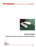
1
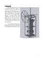
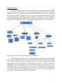
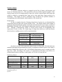
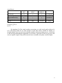
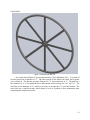
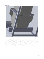
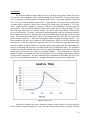
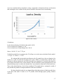
Hops Baler 2.0 Project
Mentor: Dr. Mike Rosen
Clients: UVM Extension
By: Ryan Rzepka, Yuri Hudak, and John Repucci
Disclaimer
1
With respect to the University of Vermont College of Engineering and Mathematical Sciences:
The intent of this report is to present the design, analysis, prototype realization and test of
a hops baler for the Hops Baler 2.0 project. The work presented here was performed as a twosemester long project as a part of the UVM School of Engineering’s Capstone Design courses
(ME 185/186, EE 187/188) instructed by Professors Frolik and Novotny. Although we have
exercised utmost care while working on all components of this project, the reader should be
aware that the work was performed within a short time period and by students. This work was
directed and reviewed by the course instructors and Dr. Mike Rosen.
The reader is advised that before using any part of this report or the device itself, the
work should be independently evaluated.
In receiving the prototype device, the Client understands that UVM is not warranting or
representing that the device is functional for any particular purpose in its existing form. The
Client agrees to indemnify, defend and save harmless UVM, it agents, students and employees
from any and all liability, claims, causes of action or demands of any kind and nature which may
arise in connection with this device.
John Repucci
Yuri Hudak
Ryan Rzepka
Rosalie Madden
Heather Darby
With respect to the University of Vermont Extension:
This report and associated design documents are provided “as-is” without guarantee or
warranty of any kind to communicate the findings of a research project with the aim of
developing a small-scale hops baler for use in the Northeastern United States. The design is
based on standard practices in agricultural equipment operation. This description of the machine
is based on the first year of operation (one harvest season), during which several modifications
were made. The design team expects future modifications will also be made as improvements are
sought to the machine’s functionality and as maintenance is required. Additionally, the design
should be reviewed for relevance to the user/reader’s specific location and operation. The design
of this machine assumes experienced and attentive operation teams who demonstrate safe
practices when using equipment. The machine is not intended to be operated unattended or by
unskilled operators. Risks of bodily injury, include, but are not limited to those that may occur as
the result of various pinch points. Any deviation from the design may create safety risks that are
unknown to the designers. UVM, NeHA, their employees and their contractors do not assume
liability for any actions or machine assemblies that result in personal injury or loss of property or
damage to property on the part of the user of these documents or any operators of the equipment.
2
To:
Dr. Heather Darby
Rosalie Madden
In our report, there are detailed description and analyses of all parts of the Hops Baler 2.0
Project. We clarify the objectives and constraints to show we have met all the requirements you
were looking for. We have designed and built our machine to the best of our abilities and are
glad you approve of our work. We cannot thank you enough, Heather and Rosalie, for the
opportunity and support throughout the year. We also appreciate the insight and wisdom of Dr.
Mike Rosen who constantly pushed us to better our project. We have learned so much
throughout the whole project and would not have been able to if it were not for our sponsors
UVM Extension, SEED, and the College of Engineering and Mathematical Sciences. We were
also funded in part by the Vermont Agricultural Innovation Center through the United States
Department of Agriculture, Rural Development. These funds were secured through the efforts of
Senator Patrick Leahy. We could not have done it without all these great people and programs.
3
Table of Contents
Problem Statement...........................................................................................................................5
Design Overview.............................................................................................................................6
Objective Analysis...........................................................................................................................7
Function Analysis............................................................................................................................8
Design Details................................................................................................................................10
Test Results....................................................................................................................................16
Analysis.........................................................................................................................................21
Conclusion.....................................................................................................................................22
User Manual...................................................................................................................................23
Budget............................................................................................................................................24
Bill of Materials.............................................................................................................................27
Schedule.........................................................................................................................................28
Test Plans.......................................................................................................................................29
4
Problem Statement
Vermont and other Northeastern states have seen resurgence in hops production. The
demand for locally produced foods has spurred an interest by microbreweries to search out local
hops. The small acreage of Northeastern hop farms requires scalable production and processing
infrastructure. The available hops balers are aimed at major producers that construct a 200 lb
bale. Our team will develop an alternative design, aimed at producing 5-10 lb bales using human
power, with a particular emphasis on preserving quality, safety, low cost and time efficiency.
5
Design Overview
The design uses human power with
a mechanical advantage to supply an
uncompressed volume of hops with a load
large enough to compress them down to a
small, compact bale. The initial volume of
hops is determined by a value for the
initial density, which was found through
test trials in the materials testing
laboratory. The density of hops varies
depending on how long they have been
drying, hop variety, and level of
compaction prior to entering the baler.
With this in mind, an initial density value
was chosen that took all of those aspects
into consideration.
A final Solidworks model of our
design can be seen in Figure 1. The design
and subsystems will be explained in detail
in the Design Details section of this report.
Figure 1. Final Solidworks model for Baler 2.0.
6
Objective Analysis
Through an aggregate rank ordering, four basic objectives were determined for the hops
baler, as seen below in the objective tree. We determined that the baler needed to be scalable to
produce bales from 5 to 10 pounds, that it needed to be automated in the sense that a continuous
flow could be established, it needed to be safe i.e. no exposed sharp edges and no risk of getting
caught in moving parts, and most importantly it needed to be marketable. In order to determine
how well our final design will fulfill each of these objectives, we constructed a metrics chart and
used projected values for each objective to determine a final performance score of our design.
Figure 2. Metrics chart used to determine final performance score for Baler 2.0.
Our device has met all the objectives besides automation, safety guards and lightweight.
When we were initially listing objectives we thought our baler would be powered pneumatically
or by electricity, but after testing we determined that all power requirements could be satiated
with human power. By making the machine human powered we actually increased its
marketability (one of our objectives) because the baler produces zero carbon emissions. The
safety guard objective was simply not met because we did not completely enclose the gearbox.
We did not enclose the gearbox because we wanted easy access to it in case anything went
wrong. Although the baler is not lightweight, it also is not very heavy. It is easily transported by
removing the crank wheel and moving it with a hand dolly.
7
Function Analysis
To perform a function analysis we mapped out the flow of inputs, sub-functions, and
means in a function-means tree. This provided us with an excellent organized graphic of the
required steps involved in manufacturing a hops bale, and the required inputs and means that
would be needed to accomplish these steps and at what point these inputs needed to be
introduced. This helped us look at individual steps and discuss all possible methods of
accomplishing each, and ultimately which method we felt was the best.
Requirements:
In order to complete the task of forming a hops bale of a given size, we determined four
requirements that the hops baler design needed to have. The design needed some method of
packaging and maintaining hop quality, an adequate mechanical power source input, a method of
adding hops efficiently, and a well designed compression system to actually press the hops into a
bale. Through a brainstorming session we found several means of accomplishing each
requirement in order to allow for a broad range of design ideas which we could later narrow
down based on a ranking system as well as experimentation.
Function
Requirement
Unite Hops to Bag
Compress Hops
Allow Bale to Form
Vacuum Sealed
Seal the Bag
No Loss of Hops
Achieve Desired Density
Create Stackable Shape
Eliminate All Air
Food Grade
Our device met all of the requirements that we had set in December. The baler had some
method of packaging and maintaining hop quality, an adequate mechanical power source input, a
method of adding hops efficiently, and a well designed compression system to actually press the
hops into a bale. According to the metrics we constructed in December (seen below) we
predicted that the baler would have a total quality of 0.56 with 1.0 being the best.
Preliminary Metric:
Best Case
(BC)
10
Worst Acceptable
(WA)
1
Estimated
Actual (A*)
5
0.444444444
100
300
150
0.75
Longest Dimension (ft)
4
7
5
0.666666667
Life Span (years)
15
1
6
0.357142857
Price ($)
300
2000
1000
0.588235294
Bale Size (lb)
Machine Weight (lb)
W*
W*=(A*-WA)/(BC-WA)
Q=Quality=∑(W*)/n
Q=0.56
8
Actual Metric:
Best Case
(BC)
10
Worst Acceptable
(WA)
1
Estimated
Actual (A*)
5
0.444444444
100
300
225
0.375
Longest Dimension (ft)
4
7
5
0.666666667
Life Span(years)
15
1
15
1
Price ($)
300
2000
1578.4
0.248
Bale Size (lb)
Machine Weight (lb)
W*
W*=(A*-WA)/(BC-WA)
Q=Quality=∑(W*)/n
Q=0.55
By inputting all of the actual numbers post-testing, our total actual quality achieved is
0.55. The quality found for our final product is much lower than it should be. Initially we
decided upon the best case and worst acceptable numbers during our design process. At that time
we did not fully understand the magnitudes of our features, especially for our best case price and
worst acceptable weight. If they had been made more reasonable, the quality would be higher.
9
Design Details
Frame:
Figure 3 shows the frame portion
of the design. It is made entirely of 5/4”
wide by 3/16” thick square angle iron
stock. The frame dimensions are 2’ by 2’
by 5’, and all the pieces are welded
together.
Figure 3. Baler 2.0 frame.
10
Funnel:
Figure 4 shows the
funnel component of the
design. The funnel walls
are made of high density
polyethylene, chosen for
its low friction value,
which is held together by
aluminum angle stock
fastened with self-tapping
screws. The polyethylene
sheet material is ⅜” thick.
The screws are fastened
from the inside of the
funnel walls, and the
heads are countersunk to
prevent obstruction of the
plunger.
The funnel
dimensions are 30” high
by a 10 in² inside
dimension. The fill line
which ensures a 5 lb bale
is located at 24” from the
base of the funnel and
exactly at the start of the
angled piece where the
hops are poured in.
Figure 4. Funnel.
11
Gear Assembly:
Figure 5. Gear assembly for Baler 2.0.
The gear assembly (Figure 5) transmits the force applied on the crank wheel to the rack
and thereby to the plunger. The crank wheel is fixed to a keyed input shaft, which is fixed by
three cast iron mounted bearings and also holds the first input gear. The shaft is 30” long and
has a diameter of ¾”. It is fully keyed with a 3/16” by 3/32" keyway. The input gear has a
diameter of 5.125”, a 20º pressure angle, a pitch of 16, and a face width of ¾”. The force from
the input gear is transferred to a second 5.125” gear with the same specifications held by the
transmission shaft. This shaft transmits the force to a 2.125” gear, also with a pitch of 16, a 20º
pressure angle, and a ¾” face width, which in turn transmits the force to the rack. A second
2.125” gear is located directly below the first on a rolling shaft in order to provide bracing for the
rack. The shaft is held in the gear box by press-fit high density polyethylene spacers that fit
snugly on the roller shafts. These spacers and the gears and rollers are sandwiched by two high
density polyethylene boards made from the same material as the funnel. These boards are then
held in place by two steel plates that are welded to the cross braces. The cross braces are angle
iron of the same dimensions as the frame and are welded to the frame. All gears are held in
place on the shafts by keyways with key stock, and two collars with set screws for each gear.
The mounted bearings also have set screws to hold the shafts in place.
12
Plunger:
Figure 6. Plunger component for Baler 2.0.
The plunger component (Figure 6) consists of a flat plate base made of ¼” thick steel
with guide plates welded onto the top of the plate to prevent it from becoming misaligned with
the funnel and form box. Welded onto the plate is our rack, which receives the power input and
delivers it to the hops. The rack is 5’ tall and has pitch of 16 with a 20º pressure angle and is a
¾ in². The rack is braced by four angled pieces of plate steel, which are welded to both the rack
and the plunger plate. Several small holes have been drilled into the plate and small pieces of
thin rubber have been epoxied over them to act as one-way air valves. As the plunger
compresses the hops, air is released from the holes, and upon starting the upstroke the valves
close over the holes so air is not allowed to flow back into the hops.
13
Crank Wheel:
Figure 7. Crank wheel for Baler 2.0.
Our crank wheel (Figure 7) was manufactured by Clews Machining, LLC. It is made of
steel bar stock with a diameter of ¾”. The outer portion of the wheel was rolled, and 8 spokes
were welded on. The hub has an outer diameter of 2.5” and a thickness of 2”. The hub has a
bore diameter of ¾” to fit around the drive shaft and has also been keyed to 3/16” by 3/32”. The
wheel has a total diameter of 36”, which is necessary to provide the 17:1 gear ratio desired. The
wheel also has a significant mass, which helps to act as a flywheel to store momentum when
completing the compression stroke.
14
Shaper Box:
Figure 8. Baler 2.0 shaper box.
Our bale shaper box (Figure 8) is constructed of the same material as the funnel, but
instead of being braced by aluminum angle stock it is braced by steel to provide a stronger
skeleton. The box is 12.75” tall, with a 10” inner footprint. The base of the box is a 10.75 in²
piece of plate steel with a ¼” thickness. Two of the sides opposite each other are not fixed into
the box but instead are held in place by small pieces of angle iron welded to the base plate on the
inside of the box. This design feature allows the pieces to be removed easily which makes
removing the bale very smooth.
15
Test Results
We built and refined a hops testing device to be used in conjunction with the University
of Vermont’s force transducer in the materials testing lab in Perkins 003. Testing began Friday
2/10/12 morning and yielded graphs of load and displacement. Our testing apparatus comprised
of a 1’ PVC pipe with an inside diameter of 4.1”, a plywood disc to be placed on top of the hops,
a wooden base to interface with the force transducer’s bottom plate, and another 9” PVC pipe
with a slightly smaller diameter to interface with the force transducer’s top plate and the
plywood disc. Our test method comprised of three basic steps: first, we filled the large PVC test
tube with hops which gave us a known volume. We then weighed this volume of hops which
gave us initial density. Secondly, we placed the testing apparatus on the force transducer and set
the test parameters (test rate, maximum force, and maximum displacement) and ran the test until
break. We measured the total time of the test and stopped the timer once the stress relaxation
point had been reached (i.e. when the load applied readout stopped decreasing rapidly.) The
force transducer also gave us a readout of final displacement, which we used to determine the
final density. Lastly, we removed the apparatus from the force transducer and removed the hops
from the cylinder and placed them in a separate ziplock bag marked with the trial number for
later use in detecting the presence of crushed lupulin sacs by alpha-acid testing. We conducted
six total tests and the returned data was relatively constant throughout except for the initial test
which involved some error due simply to operating blunders. The information we collected
ultimately helped us determine the total force needed as well as an approximate spring constant
for hops under compression. We also considered these calculations to determine gear type, gear
ratio, lever arm, and funnel material (i.e. strength characteristics) required for compression.
Figure 9. Load vs. time.
Note that in Figure 9 the stress relaxation period is linear because of the fact that the
force transducer stops recording force versus time once the maximum force is reached. The data
16
seen was recorded entirely manually by using a stopwatch to determine the time of relaxation
and watching the force readout for the point at which the relaxation slowed considerably.
Figure 10. Load vs. density.
Calculations:
Load at desired density of 9 lb/ft³ for the model: 100 lb
Cross sectional area of model: 13.2 in²
Cross sectional area of funnel/shaper box: 100 in²
Stress = 100 lb / 13.2 in²= 7.574 psi
To find the needed force to compress the 5 lb of hops, we use the stress calculated for the model:
7.574 psi = P / 100 in² => 757 lb
We estimated the load at the desired density to be 50 pounds lower due to relaxation. Our
model was a disk of wood that fit snugly into a pipe. When we compressed it with the force
transducer it did not exhaust air well. Once the stroke was completed, we would let the model sit
for a minute and read the force of the rebound. After the relaxation, which exhausted the air and
allowed the hop cones to settle, the rebound force was reduced to about half of the break force.
Thus, at the desired density, it had a force reading of 150 pounds and we estimated it would of
only needed 100 pounds of compression had it been better conditions.
We then related the model to our designed hops baler dimensions to find the needed force
at the end of the stroke. It came to be 757 pounds, which through proper gearing could be
achieved.
17
Figure 11. Load vs. displacement.
Using Excel’s exponential line of best fit function on the load versus displacement plot
(Figure 11) we obtained a spring force equation of F(x)=4.1437e0.5565xwith an R2 value of
0.983. The major area of variance between the equation and the data was seen in higher
displacements where the density was above our desired 9.2lb/ft3, which tells us that the variance
shouldn’t affect us much.
18
Stress testing of the frame:
Figure 12. Simulated stress test results on frame.
From the testing done in the lab, and from our calculations which can be seen above, we
conducted simulation testing on the necessary components of our design. In Figure 12, a
simulation on the frame was conducted where a 757lb load was applied to one side (which is an
extreme case since the load will be distributed between the two sides.) The stress plot shown to
the right demonstrates that the maximum stress felt by the frame is well below the yield strength
of our frame material.
19
Figure 13. Simulated stress test results on plunger.
Figure 13 shows the plunger apparatus fixed at the bottom face with a load on the top of
70000lbf, which created failure. This analysis tells us that the plunger can withstand a load
slightly less than 70000lbf, which again is well above what we expect the plunger will have to
endure.
20
Analysis
Weight of hops: 5 lb
Density of loose hops: 2.5 lb/ft³
Density of compressed hops: 9 lb/ft³
Cross sectional area of funnel/shaper box: 0.694 ft²
Maximum output force: 757 lb
Maximum input force: 50 lb
Diameter of crank wheel: 36 in
Larger gear: 5.125 in
Smaller gear: 2.125 in
To find height to the fill line, we use the density equation:
2.5 lb/ft³ = 5 lb / (0.694 ft² * h) => h = 2.882 ft
Then we find the height at which the piston head needs to stop to acquire the desired density:
9 lb/ft³ = 5 lb / (0.694 ft² * h) => h = 0.8 ft = 9.6 in
The linear travel of the piston in contact with hops:
2.882 ft - 0.8 ft = 2.082 ft
Number of crank wheel rotations for piston travel:
2.082 ft / (π * (2.125 in / 12 in/ft)) = 3.75 rev
Force multiplier:
757 lb / 50 lb = 15.14
Acquired gear ratio:
(36 in / 5.125 in) * (5.125 in / 2.125 in) = 16.94
Actual needed input force:
757 lb / 16.94 = 44.68 lb
The baler amplifies power by about 17 times the power inputted when the bale only
requires a multiplier of about 15. The extra power means the user only needs to put in about 45
pounds of force right at the end of the stroke. The good news is that the force needed to compress
the hops is exponential and only gets tougher near the desired density. The stroke is also found to
travel a linear distance of about 2.1 feet in contact with the hops. The stroke is actually a little
longer because the piston head rises above the funnel to allow the operator to pour the hop cones
in easily. But, to visualize the time it takes to form the bale, the crank wheel only spins about 4
revolutions from top to bottom.
21
Conclusions
By using only human power and a mechanical advantage of a 17:1 gear transmission, a
5lb bale can be compressed to the threshold density of 9lbs/ft3. The transverse stress that
develops as a result of the vertical compression on the hops is almost negligible, and design
considerations for this stress are minimal. After conducting multiple trials, it is clear that the
rebound of the hops after compression is small and does not interfere with bagging.
After testing, only a couple of open issues stand out. When testing, we were only able to
procure 2 year old dried up hops, which behave differently than freshly cut hops off the vine.
Fresh hops secrete a resin when crushed that could potentially clog the one way air valves.
Another issue is the possibility for the lupulin sacs to burst. It is important for the lupulin sacs to
maintain their structural integrity because they contain alpha acids which are essential in the
brewing process. The lupulin sacs bursting would be due to a final density greater than 10lb/ft3.
Future developments could include but are not limited to adjustments to increase the air
seal and subsequently the vacuum effect, designing for faster and easier bale removal, adding
incremental marks on the rack/plunger for different bale sizes and densities. The reason the
airtight seal was not achieved in time is because the epoxy that we purchased did not bond well
to the metal plunger head even after polishing. Ordering a highly adhesive epoxy would have
taken weeks to be delivered.
22
User Manual
Step by step instructions are as follows:
1) Spin the crank wheel to raise the piston to its stop point, if not already raised, and lock it
in place by moving the steel rod in the way of the crank wheel’s spoke.
2) Place vacuum sealable bag in the shaper box then slide it towards its stop and wrap the
bag around the outside of the funnel and secure in place with rubber bands.
3) Make sure the funnel and shaper box are firmly pressed against their stops so they are in
line for the piston to smoothly move inside of them.
4) Pour loose hop cones into the top of the funnel up to the fill line, which is the base of the
angled polyethylene plastic.
5) Once filled, remove the stop from the crank wheel’s spoke and begin spinning it and thus
compressing the hops until the piston reaches its final position which is held by a stop on
the rack.
6) To allow some relaxation to occur, place the crank wheel stop in again and let the system
sit for about a minute.
7) Remove the crank wheel stop, and quickly spin the wheel until the piston reaches the top
again and once again put the crank wheel stop back in the way of the spoke.
8) Push the funnel towards the edge of the frame and pull the shaper box towards the
opposite edge of the frame.
9) Pinch the top of the bag shut and hold tightly as you remove one or both sides of the
shaper box to make for easier removal of the bale.
10) Take the bale to a vacuum sealer to lock the bag in shape and remove the excess air.
For a YouTube video of the baler in action, please visit:
http://www.youtube.com/watch?v=8jQdQWiZ4KU
23
Budget
Preliminary Estimated Budget:
Heat Sealer/Slicer: Impulse by U-line
Frame: Twelve 6’ 90º angle steel
Plunger Rod: 5’ hollow 1’ outside diameter tube
Funnel Head/Pipe: Two 4’x4’ sheet polyetheline
Piston Head: 1’x1’ stainless steel plate
Bagging: 16”x400’ heavy duty plastic tubing
Gears: Three steel plain-bore pressure angle spur gear
Bearings: Three ⅛” lubricated steel
Drive shaft: 4’ solid steel bar
Wood: Lazy susan and shaper blocks
Piston Head Gasket: Polyethylene rubber
$215
$180
$150
$80
$75
$60
$45
$30
$20
$10
$7
Total
$872
24
Actual Budget:
Quantity
2
1
2
1
8
1
1
2
1
6
2
1
1
1
Item and Supplier
Unit Price ($) Total Price ($)
McMaster HDPE Polyethylene, 3/8"
87.47
174.94
Thick, 48" X 48"
McMaster Fully Keyed 1045 Steel
Drive Shaft, 3/4" OD, 3/16" Keyway
42.88
42.88
Width, 36" Length
McMaster Fully Keyed 1045 Steel
Drive Shaft, 3/4" OD, 3/16" Keyway
33.23
66.46
Width, 24" Length
McMaster Steel Standard Key Stock,
2.74
2.74
3/16" X 3/16", 12" Length
McMaster Black-Oxide Steel Set Screw
Shaft Collar, 3/4" Bore, 1-1/4" Outside
1.26
10.08
Diameter, 9/16" Width
Clews Machining (Crank Wheel)
350
350
McMaster FDA Compliant Neoprene
Rubber, 1/8" Thick, 12" x 24", 55A
32.32
32.32
Durometer
McMaster Steel 20 Degree Pressure
Angle Spur Gear, 16 Pitch, 32 Teeth, 2"
33.54
67.08
Pitch Diameter, 3/4" Bore
McMaster Impact-Resistant UHMW
Polyethylene Tube, 1-3/8" OD X 3/4"
7.87
7.87
ID, 1' Length
McMaster Cast Iron Base-Mounted
Steel Ball Bearing, Set-Screw Lock, for
39.08
234.48
3/4" Shaft Diameter
McMaster Steel 20 Degree Pressure
Angle Spur Gear, 16 Pitch, 80 Teeth, 5"
77.37
154.74
Pitch Diameter, 3/4" Bore
McMaster Steel 20 Degree Pressure
Angle Spur Gear Rack, 16 Pitch, 1/2"
64.46
63.46
Face Width, 1/2" Height, 6' Length
Sears Clear Food Grade Silicone Sealant
8.35
8.35
ULine 24X24 6MIL POLYBAG 200
140
140
Queen City Steel
153.00
Aubuchon Hardware
25.00
West Marine
45.00
Total Price
$1578.4
Our clients assigned us a budget of $2000 and we were able to complete the project with
a reasonable final price. Most of our parts were bought from the McMaster-Carr online store and
Queen City Steel. Our most expensive item, the crank wheel, was outsourced to Clews
Manufacturing and cost $350. Initially we just wanted them to roll the outside handle of the
25
wheel but they suggested we have them build the whole thing. Allowing them to make the crank
wheel did save time and is probably stronger and more precise than we could have managed. The
second most expensive item was the vacuum sealable bags from ULine. The ULine poly bags
only come in 200 count, so ordering the 10 bags we needed to do the testing could only be done
in bulk. Also, to insure durability, we made the baler extra robust and designed all the weight
bearing items out of steel. In hindsight, we could have used strong wood for many of the
features, which could reduce the price. The cost of labor is also not included because all of our
work was done for our own learning and experience. The hops baler is designed for local farmers
who will probably build their own baler based on our design and the size of their crop yield.
26
Bill of Materials
Part Name
Size
Funnel/ Shaper Box
Material
Supplier and Catalog
Number
Amount
Unit Cost
($)
Total Cost
($)
3/8" Thick, 48" x 48"
3/4" OD, 3/16" Keyway
Fully Keyed Drive Shaft
Width, 36" Length
3/4" OD, 3/16" Keyway
Fully Keyed Drive Shaft
Width, 24" Length
HDPE Polyethylene
McMaster 8619K437
2
87.47
174.94
1045 Steel
McMaster 1497K62
1
42.88
42.88
1045 Steel
McMaster 1497K61
2
33.23
66.46
Standard Key Stock
3/16" X 3/16", 12" Length
Steel
McMaster
98535A140
1
2.74
2.74
Set Screw Shaft Collar
3/4" Bore, 1-1/4" OD, 9/16"
Black-Oxide Steel
Width
McMaster 9414T15
8
1.26
10.08
Crank Wheel
36" Outside Diameter
Outsourced to Clews
Machining
1
350
350
1
32.32
32.32
2
33.54
67.08
1
7.87
7.87
6
39.08
234.48
2
77.37
154.74
1
64.46
64.46
Uline S-3628
1
140
140
Steel
FDA Compliant Air
Valves
20 Degree Pressure
Angle Spur Gear
1/8" Thick, 12" x 24", 55A
Neoprene Rubber
McMaster 8616K44
Durometer
16 Pitch, 32 Teeth, 2" Pitch
Steel
McMaster 5172T23
Diameter, 3/4" Bore
1-3/8" OD X 3/4" ID, 1'
Impact-Resistant Rollers
UHMW Polyethylene McMaster 8705K37
Length
Base-Mounted Steel Ball
3/4" Shaft Diameter
Cast Iron
McMaster 6244K53
Bearing Set-Screw Lock
20 Degree Pressure
16 Pitch, 80 Teeth, 5" Pitch
Steel
McMaster 5172T25
Angle Spur Gear
Diameter, 3/4" Bore
20 Degree Pressure
16 Pitch, 3/4" Face Width,
Steel
McMaster 6295K124
Angle Spur Gear Rack 3/4" Height, 6' Length
ULine Poly Bag (200
count)
24" x 24", 6 mil Thick
Polyethylene
Nuts and Bolts
2", 3/8" Diameter
Self Tapping Screws (80
1/8"
count)
JB Weld Cold Welding
1 Package
Compound
Steel
Aubuchon Hardware
12
1.75
21
Steel
Aubuchon Hardware
1
3
3
Epoxy
JB Weld 8265S
1
5
5
Frame Angle Iron
5/4" x 3/16", 20' Length
Steel
Queen City Steel
3
24
72
Angle Aluminum
5/4" x 3/16", 20' Length
Aluminum
Queen City Steel
1
27
27
Sheet Metal
1/4" Thick, 2'x 3'
Steel
Queen City Steel
1
29
29
Final Cost
1505.05
27
Schedule
Figure 14. Preliminary Gantt chart.
Figure 15. Final Gantt chart.
Our preliminary Gantt chart had us completing many parts of our project before the
actual completion of them. We finished many of our features later than expected due to
complications during the building process and the high demand for machine shop time. We also
had our crank wheel come in a week later than expected when it was already arriving late in the
building process. All in all, the entire build took more time and effort than expected.
28
Test Plans
Once we completed the hops baler, we tested it in outside conditions. We went through
the whole process from attaching the bag and pouring hops in to compressing the bale and
removing from the shaper box. The process from start to finished bale takes about 2 minutes. We
were unable to use the vacuum sealer for our final step because our clients possess it. Instead we
folded the excess bag neatly and duct taped it, which proved to help the bale withhold its shape
for a few hours. If the bale is properly heat sealed then it will hold its shape as long as the bag is
not punctured.
We also allowed some select guests at the University of Vermont’s design night to spin
the crank wheel and feel the max force at the end of the stroke. Observing their cranking styles
and the machine stability has proven that the baler is quite balanced and has no reason to tip or
slide.
For a YouTube video of the baler in action, please visit:
http://www.youtube.com/watch?v=8jQdQWiZ4KU
29