1
smar - DataWorX
First in Fieldbus
USER’S MANUAL
DataWorX
MAY / 06
DataWorX
VERSION 8
TM
FOUNDATION
P V I E WD WK M E
www.smar.com
Specifications and information are subject to change without notice.
Up-to-date address information is available on our website.
web: www.smar.com/contactus.asp
Table of Contents
TABLE OF CONTENTS
CHAPTER 1 - STARTING THE DATAWORX CONFIGURATION ............................................................. 1.1
INTRODUCTION TO DATAWORX ............................................................................................................................ 1.1
SOFTWARE LICENSING PROTECTION NECESSARY FOR RUNTIME MODE..................................................... 1.1
DATAWORX INTERFACE WITH THE PROCESSVIEW SECURITY APPLICATION............................................... 1.1
KEY DATAWORX CAPABILITIES ............................................................................................................................. 1.1
FEATURES OF DATAWORX..................................................................................................................................... 1.2
DATAWORX AS AN "OPC BRIDGE" ........................................................................................................................................1.3
DATAWORX OPC SERVER REDUNDANCY ...........................................................................................................................1.4
DATAWORX OPC AGGREGATION..........................................................................................................................................1.6
DATAWORX GLOBAL VARIABLES..........................................................................................................................................1.7
STARTING THE DATAWORX CONFIGURATOR ..................................................................................................... 1.7
CREATING A NEW CONFIGURATION..................................................................................................................... 1.7
TOOLBAR................................................................................................................................................................... 1.8
MENUS....................................................................................................................................................................... 1.9
FILE MENU ...............................................................................................................................................................................1.9
EXPORTING CONFIGURATION DATA ..................................................................................................................................1.10
IMPORTING CONFIGURATION DATA...................................................................................................................................1.12
ACTIVATING THE DATABASE ...............................................................................................................................................1.15
EDIT MENU.............................................................................................................................................................................1.15
MULTIPLYING ITEMS.............................................................................................................................................................1.15
VIEW MENU............................................................................................................................................................................1.16
SELECTING LANGUAGES .....................................................................................................................................................1.17
GO MENU ...............................................................................................................................................................................1.17
ACTION MENU .......................................................................................................................................................................1.18
TOOLS MENU.........................................................................................................................................................................1.18
OPTIONS.................................................................................................................................................................. 1.18
GENERAL TAB .......................................................................................................................................................................1.18
BROWSE INTERFACE TAB ...................................................................................................................................................1.19
HELP MENU............................................................................................................................................................................1.19
CHAPTER 2 - CONFIGURING THE ADDRESS SPACE ........................................................................... 2.1
OVERVIEW OF ADDRESS SPACE CONFIGURATION ........................................................................................... 2.1
FOLDERS................................................................................................................................................................... 2.1
CREATING NEW FOLDERS.....................................................................................................................................................2.1
REGISTERS............................................................................................................................................................... 2.2
REGISTER NAMES...................................................................................................................................................................2.2
REGISTER OUTPUTS ..............................................................................................................................................................2.3
USING REGISTERS..................................................................................................................................................................2.3
REGISTERING RUNNING INSTANCES...................................................................................................................................2.4
CREATING NEW REGISTERS.................................................................................................................................. 2.4
CONFIGURING REGISTER PROPERTIES .............................................................................................................. 2.5
REGISTER SETTINGS: PROPERTIES TAB ............................................................................................................................2.5
REGISTER SETTINGS: INPUT TAB.........................................................................................................................................2.6
INPUT TAB: OPC POINT ..........................................................................................................................................................2.7
INPUT TAB: REGISTER............................................................................................................................................................2.7
INPUT TAB: NONE....................................................................................................................................................................2.8
INPUT TAB: EXPRESSION.......................................................................................................................................................2.8
INPUT TAB: CONDITION CRITERIA ........................................................................................................................................2.9
INPUT TAB: CONDITION RESULT.........................................................................................................................................2.10
INPUT TAB: CONDITION INPUTS..........................................................................................................................................2.10
REGISTER SETTINGS: OPC OUTPUTS TAB........................................................................................................................2.11
ALIASES................................................................................................................................................................... 2.11
CREATING NEW ALIASES...................................................................................................................................... 2.12
CONFIGURING ALIAS PROPERTIES .................................................................................................................... 2.13
ALIAS SETTINGS: PROPERTIES TAB...................................................................................................................................2.13
ALIAS SETTINGS: INPUT TAB ...............................................................................................................................................2.14
ALIAS SETTINGS: OPC OUTPUTS TAB................................................................................................................................2.15
ALIAS SETTINGS: BROWSE INTERFACE TAB.....................................................................................................................2.15
SWITCH ALIASES ................................................................................................................................................... 2.16
CREATING NEW SWITCH ALIASES ...................................................................................................................... 2.16
III
DataWorX Configurator – User’s Manual
CONFIGURING SWITCH ALIAS PROPERTIES ..................................................................................................... 2.17
SWITCH ALIAS SETTINGS: PROPERTIES TAB ...................................................................................................................2.18
SWITCH ALIAS SETTINGS: INPUT TAB................................................................................................................................2.18
SWITCH ALIAS SETTINGS: OPC OUTPUTS TAB.................................................................................................................2.19
SWITCH ALIAS SETTINGS: BROWSE INTERFACE TAB .....................................................................................................2.20
SWITCH ALIAS SETTINGS: VALUES TAB ............................................................................................................................2.20
SWITCH ALIAS SETTINGS: INPUT LIMITS TAB ...................................................................................................................2.21
EXAMPLE OF USING A SWITCH ALIAS ................................................................................................................ 2.21
REDUNDANCY ALIASES ........................................................................................................................................ 2.22
CREATING NEW REDUNDANCY ALIASES ........................................................................................................... 2.22
CONFIGURING REDUNDANCY ALIAS PROPERTIES.......................................................................................... 2.23
REDUNDANCY ALIAS SETTINGS: PROPERTIES TAB ........................................................................................................2.24
REDUNDANCY ALIAS SETTINGS: OPC OUTPUTS TAB......................................................................................................2.25
REDUNDANCY ALIAS SETTINGS: REDUNDANCY TAB ......................................................................................................2.25
CHAPTER 3 - RUNTIME OPERATIONS .................................................................................................... 3.1
DATAWORX RUNTIME ENVIRONMENT.................................................................................................................. 3.1
STARTING AND STOPPING RUNTIME MODE........................................................................................................ 3.1
MONITOR VIEW ........................................................................................................................................................ 3.1
MONITOR VIEW REFRESH RATE ........................................................................................................................... 3.2
ENABLE MONITORING ............................................................................................................................................. 3.2
DISABLE MONITORING ............................................................................................................................................ 3.2
RUNNING DATAWORX AS A SERVICE................................................................................................................... 3.3
OLE AUTOMATION IN DATAWORX......................................................................................................................... 3.3
DWXRUNTIME OBJECT...........................................................................................................................................................3.4
IPOINT INTERFACE .................................................................................................................................................................3.4
IREGISTER INTERFACE ..........................................................................................................................................................3.4
IREDUNDANCYALIAS INTERFACE .........................................................................................................................................3.5
IV
Chapter 1
STARTING THE DATAWORX
CONFIGURATION
Introduction to DataWorX
DataWorX is a 32-bit, multithreaded, OPC-compliant client and server application providing multiple
functionality. DataWorX is a component of the ProcessView product family, and it serves as a
project-level data system for ProcessView applications. Acting as a bridge between various OPC
servers, DataWorX provides different OPC data channels. Once multiple I/O channels are
established between PCs, DataWorX will switch between a primary PC (node) and a backup PC on
the network. Should the primary PC be disabled, DataWorX will automatically (should the options be
specified) default to the backup PC and vice versa. Another feature of DataWorX is the use of global
variables that are accessible from multiple clients.
Software Licensing Protection Necessary for Runtime Mode
DataWorX is installable as a stand-alone COM component. It registers itself with the ProcessView
license protection mechanisms. DataWorX permits unlimited configuration capabilities with or
without the software license protection present. It requires software license protection to work in
runtime mode. If such licensing is not present, DataWorX runs for two hours in runtime mode before
timing out.
DataWorX Interface With the ProcessView Security Application
From within the security configuration application, you can restrict access to the various features
and/or data available via DataWorX.
DataWorX supports multiple languages. That is, menu items, forms and various other text items are
available for translation into other international languages through the ProcessView Language
Configurator.
Key DataWorX Capabilities
DataWorX is an OPC-compliant server and client that conforms to Microsoft COM/DCOM program
practice. The main features of DataWorX include:
•
OPC data-bridging and sharing between OPC servers.
•
OPC server redundancy with auto switchover.
•
OPC data aggregation for better performance and more efficient data management.
•
Global variables for OPC aliasing and expressions.
1.1
DataWorX Configurator – User’s Manual
DataWorX Features
Features of DataWorX
The main features of DataWorX include the following:
1.2
•
Serves as an OPC data bridge between OPC servers.
•
OPC server redundancy with auto-switchover performance.
•
OPC client request aggregation.
•
Global variables.
•
Register grouping and organization.
•
Can be run as a service.
•
OPC interface on both the client side and server side.
•
Switch alias functionality.
•
OLE automation interface.
•
Conditions that can be used as register inputs.
•
Time stamp and quality to points accessed via automation.
•
Output to NT Event Logger.
•
Support for GenBroker OPC over TCP/IP and SOAP/XML communications.
•
Filter support.
•
Statistics and performance analyzer.
•
Startup with a specified file.
•
Primary node status register.
•
CSV file import and export.
•
XML file import and export.
Starting the DataWorX Configuration
•
Runtime command line option.
•
Global aliasing support for OPC inputs and outputs.
•
Changes made to DataWorX registers that are made together (in a single call to the OPC
interface) are also made together. OPC clients connected to DataWorX are notified about all
the changes in a single update.
•
NATIVE register type for array support.
•
Optional refresh mechanisms.
•
Integrated Expression Editor.
•
Disable OPC propagation support.
•
New way of registering running instances.
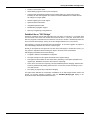
DataWorX As an "OPC Bridge"
Customers sometimes need to pass information from one device on to another. For example, data
from one brand of PLC need to be shared with another I/O device. In the past, users had to write
their own programs to translate and move data from one server to another. DataWorX provides this
server-to-server data exchange, serving as an "OPC bridge" between two or more servers.
OPC bridging is a unique and powerful feature of DataWorX. As its name suggests, its purpose is
to provide "bridging" between OPC servers of various types.
Should you be required to scan input from one OPC server and supply it to another OPC server, you
may "perform" expressions before sending the output to the other server via DataWorX.
OPC bridging in DataWorX involves the following:
•
A register is defined in the DataWorX Configurator.
•
The input and output for the register are defined in the register settings.
•
This register is also available to other clients while, depending on the options specified for the
register input, DataWorX continues to write values to output tags.
•
There can be more than one output tag. This way DataWorX performs "bridging" between OPC
servers by simultaneously reading values from one or more OPC servers and writing to one or
more OPC servers.
•
No scripting or programming is required for bridging.
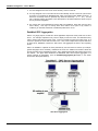
The figure below illustrates the functionality of DataWorX as an OPC bridge between clients and
servers. For another example of bridging, open the DataWorX_Bridging.gdf display in the
"Smar\ProcessView \Examples\GenDemo" directory.
1.3
DataWorX Configurator – User’s Manual
OPC Server Bridging
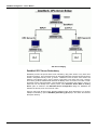
DataWorX OPC Server Redundancy
DataWorX provides 100 percent OPC server redundancy using OPC servers to any OPC client
through the network. This means that users can designate alternative machines as backup servers
should a designated Primary server go offline. DataWorX scans the OPC server status and
switches to the Backup node in case of Primary node failure. This means that, once a Primary
server does go offline, DataWorX will default to the Backup server or servers in the order in which
the backup servers were designated. A special digital tag is provided to start events in case of a
switchover from the Backup to the Primary server. If the Automatic Switch Back to Primary
Server option is selected in the Redundant Server Configuration dialog box, DataWorX will
default to the Primary server once it returns online.
Figure A and Figure B shown below illustrate DataWorX OPC Server Redundancy. For another
example of redundancy, open the DataWorX_Redundancy.gdf display in the "Smar/ ProcessView
/Examples" directory.
1.4
Starting the DataWorX Configuration
Redundancy When the Primary OPC Server Is Online
Redundancy When the Primary OPC Server Is Offline
1.5
DataWorX Configurator – User’s Manual
1. You must designate one OPC server as the "Primary" server in each set.
2. You may designate one or more OPC servers as the "Backup" servers in each set. (This number
of servers is not restricted by DataWorX itself; rather it is limited only by system resources). If
more than one backup server is specified, they should be ordered (2nd, 3rd, 4th, etc.) You will
see a message outlining the details of the discrepancies, and will be allowed to either accept it
as is or permit reconfiguration.
3. The various OPC client applications request data from DataWorX, rather than from the OPC
server directly. This way if a Primary OPC server failure occurs (due to any number of
conditions), an automatic switchover to the Backup OPC server occurs.
DataWorX OPC Aggregation
Often in very large projects, several OPC client applications request the same points from an OPC
server. For example, GraphWorX may need to display a tank level value, and AlarmWorX may
need to monitor and alarm that same value. This may increase the load of the OPC server, as it
now has to provide the same data more than once. Thus, when multiple clients request data from
an OPC server, DataWorX monitors the OPC server and aggregates the data to the requesting
clients.
Often it is desirable to optimize the work performed by the lower-level I/O servers (for example,
greater throughput can be achieved). DataWorX can serve as a "middle-man" between clients and
servers and assist in this optimization process. This is beneficial especially with remote servers over
the network. The figure below illustrates the DataWorX OPC client request aggregation. For
another example of aggregation, open the DataWorX_Aggregation.gdf display in the "Smar/
ProcessView /Examples" directory.
OPC Server Aggregation
1.6
Starting the DataWorX Configuration
DataWorX Global Variables
Many clients require a common variable to share values. DataWorX makes it possible to define
many variables that are accessible to many clients simultaneously. The DataWorX registers can be
used as global variables. These variables can also act as aliases for clients. You can create holding
registers, data filters, global registers, and switches for your entire project, as well as define data
types, ranges, read/write status, and more.
Starting the DataWorX Configurator
To start the DataWorX Configurator:
1. From the Windows Start menu, select Programs > Smar ProcessView > ProjectWorX >
DataWorX.
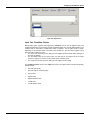
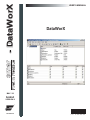
2. This opens the DataWorX Configurator, as shown in the figure below. The screen consists of a
split window with a tree control view in the left-hand pane and a configuration view in the righthand pane. The Configurator provides a standard format for the configuration database, as well
as a sample (default) DataWorX configuration project. The Configurator also includes a toolbar
and menus with many command functions.
DataWorX Configurator Screen
Creating a New Configuration
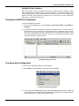
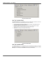
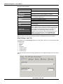
To create a new configuration database in the Configurator:
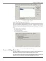
1. Select New from the File menu, as shown in the figure below.
Creating a Configuration Database
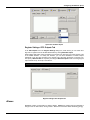
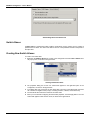
2. In the Save New Database dialog box, select the database type from the Save As
Type drop-down list, as shown in the figure below. Browse for the target directory,
give the file a name, and then click the Save button.
1.7
DataWorX Configurator – User’s Manual
Saving the New Configuration Database
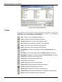
Toolbar
The Configurator toolbar, shown below, contains the following command buttons. To show or hide
the Standard toolbar, select Toolbars > Standard Buttons from the View menu. The Standard
toolbar, shown below, contains the following command buttons.
New: Creates a new configuration database.
Open: Opens an existing configuration database.
Up One Level: Moves up one level in the tree control.
Cut: Deletes current selection, sending it to the clipboard.
Copy: Copies the current selection to the clipboard.
Paste: Pastes the current contents of the clipboard.
New Register: Creates a new register under the Address Space tree
control.
New Alias: Creates a new alias under the Address Space tree control.
New Switch: Creates a new switch under the Address Space tree control.
Large Icons: Displays items as large icons.
Small Icons: Displays items as small icons.
List: Displays items as a list.
Details: Displays items as a list with details.
Dialog View: Displays additional configuration options.
Runtime: Starts/stops the DataWorX server.
Monitor View: Displays OPC data in a separate pane.
Update Runtime: Refreshes the DataWorX configuration during runtime.
About: Displays information about the application.
1.8
Starting the DataWorX Configuration
Menus
The menu bar of the Configurator contains the following menus:
•
File
•
Edit
•
View
•
Go
•
Action
•
Tools
•
Help
NOTE
You can also access many of the menu commands by right-clicking items in the tree control of
the Configurator and selecting command functions from the pop-up menus.
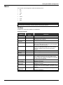
File Menu
The File menu commands are listed in the table below.
File Menu Commands
COMMAND
New
Open
Save As
Connection
Properties
Export CSV
Import CSV
XML Export
XML Export
Schema
XML Import
XML Validate
DataWorX
Binary Export
DataWorX
Binary Import
Make Active
Update Runtime
Configuration
Exit
SHORTCUT
KEYS
CTRL+N
CTRL+O
FUNCTION
Creates a new configuration database.
Opens an existing configuration database.
Saves the current database under a different name as a
Microsoft Access (.mdb) file.
Displays the current database connection properties.
Exports configuration data from your database to a text
file (.txt) or a Microsoft Excel file (.csv). You can specify
the delimiters and what to export.
Imports data into your configuration database from a text
file (.txt) or a Microsoft Excel file (.csv). You can then
specify the delimiters and choose from the import
settings.
Exports configuration data to an XML file.
Exports configuration data to an XML Schema file.
Imports configuration data from an XML file.
This feature does not import an XML data file, but it will
try to validate its structure using stored XML schema.
Once it passes this validation, the XML file is acceptable
for import by the Configurator.
Exports configuration data to an older version of
DataWorX (.dwx files).
Imports configuration data from an older version of
DataWorX (.dwx files).
Activates the current database. If this command is not
available, then the current database is already the active
database.
Refreshes the DataWorX configuration during runtime.
Closes the application.
1.9
DataWorX Configurator – User’s Manual
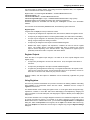
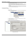
Database Connection Properties
Selecting Connection Properties from the File menu opens the Database Connection Properties
dialog box, shown below, which lists the initialization properties for the current database connection.
Database Connection Properties Dialog Box
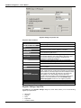
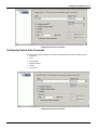
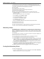
Exporting Configuration Data
Exporting Data to a Text or CSV File
The Configurator offers the flexibility of exporting data from your configuration database to a text
(.txt) file or a Microsoft Excel (.csv) file. To export data, select Export CSV from the File menu. This
opens the Export Configuration Data to File dialog box, as shown in the figure below. You can then
specify the delimiters for exporting the data. Unless you specify delimiters in the Export
Configuration Data to File dialog box, the file uses Commas as delimiters by default. Each group
contains headings and columns that provide information about each item, such as descriptions and
associated translations and expressions. It also provides the "tree" pathway for each item. Choose
the directory to which you want to export the data from your database. In the Save As Type field,
choose the file type (.txt or .csv) that you would like to save.
1.10
Starting the DataWorX Configuration
Exporting Configuration Data
Exporting Data to an XML File
The Configurator also allows you to export data from your configuration database to an XML file.
The XML export/import functionality was mainly developed for Windows platforms that do not
support databases (e.g. Windows CE and Windows Embedded). XML has the following advantages
over the CSV import/export function:
•
XML has a standardized format, unlike the text/CSV format, which uses various delimiters (e.g.
TAB instead of commas, strings could not accept all characters, etc.)
•
XML is language-independent, whereas CSV converts date/time, floats, and currency fields
according to local settings in Windows. For example, using CSV, you cannot export data on
German Windows and import it on English Windows without making changes
•
Windows has an installed automation object that has the capability to work with XML. Thus,
programmers can create/modify their configurations outside the Configurator using Visual
Basic, if desired.
•
XML supports schemas. A schema is a special XML file that specifies the data structure of an
XML data file.
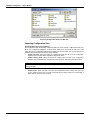
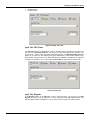
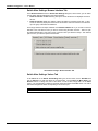
To export data, select XML Export from the File menu. This opens the Export XML File dialog box,
as shown in the figure below. Give the file a name, and then choose the directory to which you want
to export the data from your database. Click Save.
NOTE
You can also export configuration data to an XML schema file by selecting XML Export from the
File menu.
1.11
DataWorX Configurator – User’s Manual
Exporting Configuration Data to an XML File
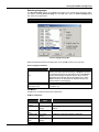
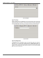
Importing Configuration Data
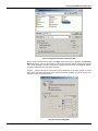
Importing Data From a Text or CSV File
The Configurator offers the flexibility of importing data from a text (.txt) file or a Microsoft Excel (.csv)
file to your configuration database. To import data, select Import CSV from the File menu. This
opens the Import Configuration Data From File dialog box, shown below. You can then specify the
delimiters and choose from the following import settings:
•
Create new items. When the import file contains items that are not yet in the configuration
database, then it creates them. Otherwise it skips these items.
•
Update existing items. When the import file contains items that are in the configuration
database, then it updates them using data from the import file. Otherwise it skips these items.
NOTE
Either Create new items or Update existing items must be selected. Otherwise there is
nothing to import.
•
1.12
Display errors. When this item is checked, the Configurator shows a dialog box if an error
occurs, and then asks you if you want to proceed with the import. When it is not checked, it
skips all items where an error occurred.
Starting the DataWorX Configuration
Import Configuration Data From File Dialog Box
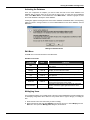
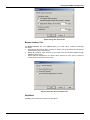
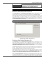
When you have selected a file to import, click Open. When the import is completed, the File Import
Results dialog box opens, as shown below. This shows the import settings, including the input file
name. It also provides a summary of the import, including how many items were inserted, updated,
or rejected, and shows how many errors occurred.
Click the ... button to the right of each field to get the details view of the import results, as shown
below. This view shows the specific items that were inserted, updated, or rejected, as well as a
description of any errors that occurred.
File Import Results Dialog Box
1.13
DataWorX Configurator – User’s Manual
Importing Data From an XML File
The Configurator allows you to import data from your configuration database to an XML file. The
XML export/import functionality was mainly developed for Windows platforms that do not support
databases (e.g. Windows CE and Windows Embedded). XML has the following advantages over the
CSV import/export function:
•
XML has a standardized format, unlike the text/CSV format, which uses various delimiters (e.g.
TAB instead of commas, strings could not accept all characters, etc.)
•
XML is language-independent, whereas CSV converts date/time, floats, and currency fields
according to local settings in Windows. For example, using CSV, you cannot export data on
German Windows and import it on English windows without making changes
•
Windows has an installed automation object that has the capability to work with XML. Thus,
programmers can create/modify their configurations outside the Configurator using Visual
Basic, if desired.
•
XML supports schemas. A schema is a special XML file that specifies the data structure of an
XML data file.
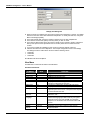
To import data, select XML Import from the File menu. This opens the Import XML File dialog box,
as shown in the figure below. Give the file a name, and then choose the directory from which you
want to import the data. You can then specify the delimiters and choose from the following import
settings. Click Open.
•
Create new items. When the import file contains items that are not yet in the configuration
database, then it creates them. Otherwise it skips these items.
•
Update existing items. When the import file contains items that are in the configuration
database, then it updates them using data from the import file. Otherwise it skips these items.
NOTES
Either Create new items or Update existing items must be selected. Otherwise there is nothing to
import.
Selecting XML Validate from the File menu does not import an XML data file, but it will try to
validate its structure using stored XML schema. Once it passes this validation, the XML file is
acceptable for import by the Configurator.
Importing Configuration Data From an XML File
1.14
Starting the DataWorX Configuration
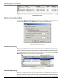
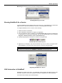
Activating the Database
Once your configuration is complete, you need to make sure that it is the active database. The
database that is currently active is the one that the server uses. To make the current database
active, select Make Active… from the File menu. If the Make Active… selection is grayed out, then
the current database is already the active database.
A dialog box appears showing both the current active database and database that is currently being
edited, as shown in the figure below. To set the edited database as the active database, click the
Yes button.
Making the Database Active
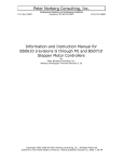
Edit Menu
The Edit menu commands are listed in the table below.
Edit Menu Commands
COMMAND
SHORTCUT
KEYS
New
Rename
Multiply
CTRL+M
Delete
CTRL+DEL
Cut
CTRL+X
Copy
Paste
CTRL+C
CTRL+V
Select All
CTRL+A
Invert Selection
FUNCTION
Creates a new item depending on what is selected in the
tree control.
Renames the selected item.
Opens the Multiply Item dialog box, which allows you to
multiply an item in the tree control.
Deletes the selected object.
Cuts the selected object from the view and places it on
the clipboard.
Copies the selected object to the clipboard.
Pastes the last object placed on the clipboard.
Selects all objects in a list. The selection is shown in the
upper-right-hand section of the viewer.
Unselects all selected items and selects all unselected
items in a list in the upper-right-hand section of the
viewer.
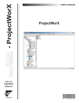
Multiplying Items
The Configurator allows you to multiply items in the tree control. Multiplication provides a simple way
of developing configurations where there are many similar items in a given category. To multiply an
item:
1. Select the item in the tree control that you wish to multiply.
2. Either right-click the item and select Multiply from the pop-up menu, or select Multiply from the
Edit menu. This opens the Multiply Item dialog box, shown below.
1.15
DataWorX Configurator – User’s Manual
Multiply Item Dialog Box
3. When the items are multiplied, they are all given a base name followed by a number. The default
base text is the name of the item selected for multiplication. To modify the base text, change the
Base Text field appropriately.
4. In the First Number field, specify the number to appear next to the first multiplied item.
5. In the Number of Items field, specify how many items you wish to create.
6. In the Numeric Places field, specify the minimum length of each number to append. Values that
take up less space than the specified amount of numeric places will have zeros before the
number.
7. If you want to multiply all subfolders as well, check the Including Subtree check box.
8. Click the OK button to do the multiplication. The example configuration shown in the Multiply
Item dialog box above creates three new items with the following names:
•
Switch001
•
Switch002
•
Switch003
All subfolders will also be multiplied.
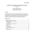
View Menu
The View menu commands are listed in the table below.
View Menu Commands
COMMAND
Toolbars
Status Bar
Large Icons
Small Icons
List
Details
Dialog View
Monitor View
Sort By
SHORTCUT
KEYS
F7
F8
F9
F10
F11
F12
Show/Hide
Columns
Select
Language
Global Refresh
Subtree
Refresh
1.16
F5
CTRL+F5
FUNCTION
Toggles the standard and data manipulation toolbars.
Toggles the status bar.
Displays items as large icons.
Displays items as small icons.
Displays items as a list.
Displays items as a list along with detailed information
about the configuration of each item.
Toggles the configuration window (right-hand pane).
Displays OPC server data in a separate pane.
Displays a list of options for sorting the columns in the
right-hand pane of the screen. The options listed depend
on the level within the view.
Displays a list of options that you can choose to show or
hide in the view.
Opens the Select Language dialog box (see below).
Choose the language you wish to use for your system
(Unicode version only) and click OK. For navigation
purposes, use the buttons and check boxes in the List
section.
Refreshes the data for the entire Configurator screen.
Refreshes only the data contained in the currently
selected subtree.
Starting the DataWorX Configuration
Selecting Languages
The Select Language function on the View menu allows you to choose which language to use in
your display. Choosing Select Language from the View menu opens the Select Language dialog
box, shown in the figure below.
NOTES
Language resource .dll is required for language switching.
Select Language Dialog Box
Define the parameters listed in the table below. Then click OK to return to the work area.
Select Language Parameters
PARAMETER
List
Installed Locales Only
Available Language
Translations Only
DESCRIPTION
Lists available languages. Depending on which item you have
selected, the view on the left will change. If English is checked,
the languages will appear as their English name. If Localized is
checked, the languages will appear with the native country in
parentheses (for languages with several dialects only). When
Native is checked, the languages are displayed the way they
would be written in that language.
If this is checked, local languages appear in the box.
Checking this box allows you to choose from available language
translations only.
Go Menu
The Go menu commands are listed in the table below.
Go Menu Commands
COMMAND
Up One
Level
Next Item
Previous
Item
Expand Item
Collapse
Item
Page Up
SHORTCUT
KEYS
FUNCTION
Moves the cursor up one level in the tree control.
ALT+Down
Arrow
ALT+Up Arrow
Moves the cursor to the next item down in the tree
control.
Moves the cursor to the next item up in the tree view.
ALT+Left
Arrow
ALT+Right
Arrow
ALT+PgUp
Expands an item that contains a submenu.
Collapses an item that contains a submenu.
Moves the cursor up to the first item in the tree.
1.17
DataWorX Configurator – User’s Manual
SHORTCUT
KEYS
COMMAND
Page Down
ALT+PgDown
Home
End
ALT+Home
ALT+End
Next Pane
Previous
Pane
F6
SHIFT+F6
FUNCTION
Moves the cursor down to the last visible item in the
tree.
Moves the cursor up to the first item in the tree.
Moves the cursor down to the last visible item in the
tree.
Moves the cursor to the next pane.
Moves the cursor to the last pane used.
Action Menu
The Action menu commands are listed in the table below.
Action Menu Commands
COMMAND
Start Runtime
FUNCTION
Starts the DataWorX runtime operation.
Stop Runtime
Stops the DataWorX runtime operation.
Tools Menu
The Tools menu opens the Options dialog box, which is described in the section below.
Options
To choose additional settings, select Options from the Tools menu. This opens the Options dialog
box, which contains the following tabs:
• General
• Browse Interface
General Tab
The General tab of the Options dialog box, shown below, contains the following options:
1.18
•
Save regional settings in registry: Checking this option allows you to save regional settings
in the registry so that they are applied each time you start the configuration application. This
applies to the language settings as well as time and date settings.
•
Automatically apply changes when selection is changed: Checking this option allows
changes to the configuration database to be saved each time you switch dialogs without
clicking on the Apply button or being shown a message asking if you would like to apply
changes.
•
Enable hover selection: Checking this option allows you to highlight an item by moving the
mouse pointer over that item and keeping it there for a specified amount of time (in
milliseconds).
•
OPC Monitoring Update Rate: This specifies the update frequency (in milliseconds) of the
items in the Monitor View. The monitor scans the server and displays the tag values at the
bottom of the Configurator screen.
Starting the DataWorX Configuration
Options Dialog Box: General Tab
Browse Interface Tab
The Browse Interface tab of the Options dialog box, shown below, contains the following
commands:
•
Browse Redundant Servers: When checked, the items of the servers defined as redundant (in
the Redundancy menu) will be shown.
•
Browse My Computer: When checked, the local OPC server and its items available through
DataWorX will be shown.
•
Browse Network Neighborhood or Internet: When checked, the OPC servers located on
remote nodes and their items will be shown.
Options Dialog Box: Browse Interface Tab
Help Menu
The Help menu commands are listed in the table below.
1.19
DataWorX Configurator – User’s Manual
Help Menu Commands
SHORTCUT
KEYS
COMMAND
Help Topics
About
Application
1.20
F1
FUNCTION
Launches the online Help for the Configurator.
Launches the About Box, which contains information
about the product version number, copyright, and
available disk space. It also contains contact information.
Chapter 2
CONFIGURING THE ADDRESS SPACE
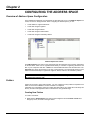
Overview of Address Space Configuration
In the DataWorX Configurator, the parameters for data items are set up in the Address Space tree
control, as shown in the figure below. When configuring the Address space, you can:
•
Create folders to organize data items.
•
Create and configure registers.
•
Create and configure aliases.
•
Create and configure switch aliases.
•
Create and configure redundancy aliases.
Address Space Tree Control
The Address Space tree control in the Configurator sets the properties and connection parameters
for all data items, which can be organized hierarchically. It is similar to organizing directories and
files on your computer's hard disk. A folder can contain additional folders and also data items. The
data items are always the branches in the tree control hierarchy. The hierarchical structure of the
folders and data items helps to organize the registers, aliases, switches, and redundancy aliases.
NOTE
The ProcessView installation provides a sample DataWorX configuration database called
DwxSampleConfigurator.mdb.
Folders
Folders can be used to group items logically. You can configure as many folders as required. Each
folder can even have subfolders. The use of folders is not required.
If desirable, the configuration could just contain data items without any folders. But most likely this
will only be useful if the application does not demand too many persistent tags.
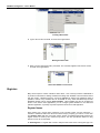
Creating New Folders
To create a new folder:
1. Right-click the Address Space tree control of the Configurator and select New > Folder from
the pop-up menu, as shown in the figure below.
2.1
DataWorX Configurator – User’s Manual
Creating a New Folder
2. Type a name for the new folder, as shown in the figure below.
Naming the New Folder
3. When you have naming the folder, press Enter. The new folder appears under the tree control,
as shown in the figure below.
New Folder Added to Tree Control
Registers
Many clients require a common variable to share values. One of the key functions of DataWorX is
to provide a mechanism for defining variables and making them available to all ProcessView clients
and OPC clients. DataWorX uses the concept of registers to achieve this. DataWorX makes it
possible to define many variables that are accessible to many clients simultaneously because
DataWorX registers can be used as global variables. These variables can also act as aliases for
clients. In the various client applications, you can configure global variables for use within that
particular application, or possibly only within a particular document for that application.
Register Names
Each register has a unique name composed of only numbers, letters, and the underscore "_"
character. DataWorX verifies the names are indeed unique, prompting you if this is not the case.
The Register name field does not accept spaces. Spaces are disabled intentionally because the
register names are used by OPC clients as tag names. The OPC specification allows for using
spaces, but it is not recommended.
An Alias Register is a register that is used to keep the alias value and is of string data type. You
2.2
Configuring the Address Space
can access it like an ordinary register. The [[ and ]] are used to expand the alias, i.e. to replace the
name of the alias with its value. For example:
Register 'REG' = 10; Alias Register 'MODBUS' = "ICONICS.ModbusOPCServer".
'DataWorX32\REG' = 10
'DataWorX32\MODBUS' = "ICONICS.ModbusOPCServer"
'DataWorX32\[[MODBUS]]Dev1.Tag1' = ICONICS.ModbusOPCServer\Dev1.Tag1 (value)
DataWorX registers are accessible through the OPC Universal Tag Browser.
DataWorX registers are accessible from VB using the "GetRegister" function of the Automation
interface.
The count limit is not restricted by DataWorX itself, but is limited by system resources.
Register Inputs
A register has one input (or source) to define its content.
•
An input may be assigned to an expression that, when resolved, defines the register's content.
•
An input may be assigned to None to create a global variable. (The initial value is selectable.)
•
An input may be assigned to an OPC data point (including the value itself, quality, and time
stamp), using the OLExpress naming convention.
•
An input may be assigned to the output of another DataWorX register.
•
Besides OPC inputs, registers, and expressions, conditions can also be used as register
inputs. The condition itself is connected to multiple OPC items or registers. One of these
inputs is chosen depending on the selected criteria. Using conditions as register inputs is
particularly useful when used in conjunction with switch aliases.
Register Outputs
When the value of a register's input changes, it is written to all of the outputs assigned to that
register (if any).
•
An output may be assigned to an item of an OPC server. Thus, the register writes values to
the server.
•
An output may be assigned to the input of another DataWorX register.
•
A register may be designated as "Read-Only." The register will still write to its outputs, but the
value can only come from an input, such as another OPC server or an expression, not from an
OPC client. If this is the case, clients may only view its contents.
Registers, aliases, and other objects in DataWorX can be hierarchically organized into groups
(folders).
Using Registers
One of the key functions of DataWorX is to provide a mechanism for defining variables and making
them available to all ProcessView clients and OPC clients. DataWorX uses the concept of
registers to achieve this.
The "Global Variable" name is simply the register's name. It can be given values through OPC tags,
expressions, constants, or even VBA. OPC server data-bridging is accomplished by assigning the
input of a register to one OPC data point, and assigning the output to different (even multiple) OPC
data points.
This section describes how to configure Registers functions in the DataWorX Configurator in order
to connect more than two servers. For example, if you want a client PC to send a value from a
Modbus OPC server to a Bristol OPC server, you can define the Register Name in the Properties
dialog box, define the Properties for that register, set the Input to the Modbus OPC server's tag,
and set the Output to the Bristol OPC server's tag for a Register Tag using the Register Settings
dialog box.
2.3
DataWorX Configurator – User’s Manual
Registering Running Instances
DataWorX now registers its dispatch pointer at GenRegistrar on startup and unregisters on exit.
Dispatch pointers may be used by Visual Basic or other applications to control a running application.
Now, a dispatch pointer to an instance of DataWorX running in both configuration mode and runtime
can be obtained. In past versions of DataWorX, this was possible only in runtime.
Creating New Registers
To create a new register:
1. Right-click the Address Space tree control of the Configurator and select New > Register from
the pop-up menu, as shown in the figure below.
Creating a New Register
2. The properties dialog box for the new register appears in the right-hand pane of the
Configurator, as shown in the figure below.
3. In the Name field, type a name for the new register.
4. When you have finished configuring the register properties, click the Apply button. The new
register appears under the tree control, as shown in the figure below.
Configuring Register Properties
2.4
Configuring the Address Space
Configuring Register Properties
The register properties dialog box contains the following tabs, as shown in the figure below:
•
Properties
•
Input
•
OPC Outputs
The Properties, Input and Output tabs are the same for different register types. The Register
Type can be modified on the Properties tab by selecting a type from the drop-down list, as shown
in the figure below. Depending on this register type, other pages appear or get hidden. For example,
aliases can be browsed, so they have the Browse Interface tab (unlike registers). On the other
hand redundancy aliases, for example, do not have inputs, so the Input tab disappears when you
select a register to be a redundancy alias. It is important to understand that everything (aliases,
switches, etc.) is a register. Its features then depend on the type of register (e.g. the data type for an
alias is always STRING).
NOTE
Each register configuration has a limit of 4 kilobytes (4,096 characters). This limit applies to the
entire register record (e.g. register name, expression strings, outputs, list of condition inputs, list
of redundancy nodes, etc.).
Configuring Register Properties
Register Settings: Properties Tab
The Properties tab in the Register Settings dialog box, shown below, allows you to set the
following register parameters, as described in the table below.
2.5
DataWorX Configurator – User’s Manual
Register Settings: Properties Tab
Properties Tab Parameters
NAME
REGISTER TYPE
AVAILABLE THROUGH
OPC
AVAILABLE THROUGH
AUTOMATION
WRITEABLE
DATA TYPE
RANGES
HIGH RANGE
LOW RANGE
DELAY
DISABLE OPC
PROPAGATION SUPPORT
A common tag name.
Specifies Register, Alias, Switch Alias, or Redundancy Alias.
Checking this box makes the register available to OPC clients.
Checking this box makes the register available to VB
applications so that it could be edited by a VB editor.
Checking this box makes the register writeable. Uncheck the
box for a read-only OPC client.
Allows you to select from the following data types: Native/Empty,
Float, Double, Boolean, Byte, Word, DWord, Character, Short,
Long, String. All data types available in GraphWorX are
supported in registers for DataWorX.
Checking this box enables the High and Low ranges fields.
You can specify a High Range in the box provided.
You can specify a Low Range in the box provided.
You can specify a delay time for the register (in milliseconds) in
the box provided.
When an OPC item is connected to a register as both input and
output, a fast sequence of writes to that register may cause item
value oscillation. (This may happen when two subsequent writes
to the register are faster than the OPC item can perform the
write operation. The acknowledge of the first write then
overwrites the second written value already being stored in the
register.) To avoid this behavior, Check the Disable input
updates propagation check box in the register properties.
NOTE
By default, the data type and range information are obtained from the input of register.
Register Settings: Input Tab
The Input tab in the Register Settings dialog box, shown below, allows you to set the following
register input parameters:
•
•
•
•
•
2.6
OPC Point
Register
None
Expression
Condition Criteria
Configuring the Address Space
•
•
Condition Result
Condition Inputs
Register Settings: Input Tab
Input Tab: OPC Point
The OPC Point section of the Input tab, shown in the figure below, specifies that the input is an
OPC item. In the Input OPC Point field, you can type in an item name (tag name) or browse for one
by clicking the ... button, which opens the Unified Data Browser. The Registered Data Type field
allows you to select from the following data types: Native/Empty, Float, Double, Boolean, Byte,
Word, DWord, Character, Short, Long, String. All data types available in GraphWorX are supported
in registers for DataWorX. You can also specify the Scan Rate for OPC inputs (in milliseconds)
Input Tab: OPC Point
Input Tab: Register
In the Register section of the Input tab, shown in the figure below, you can type in an Input
Register or browse for one by clicking the ... button, which opens the Unified Data Browser. This
lists the registers defined in DataWorX. You may select an input coming from another register.
2.7
DataWorX Configurator – User’s Manual
Input Tab: Register
Input Tab: None
Selecting the None section of the Input tab, shown in the figure below, means no input will be
provided to this register. This could be used when you want to write a value from the client and send
it to many OPC servers at the same time. This is also the mechanism for creating a global variable.
Checking the Initial Value check box allows you to specify an initial value in the field to the right.
Input Tab: None
Input Tab: Expression
The Expression section of the Input tab, shown in the figure below, allows you to specify an
expression in the box provided. Clicking the Edit button opens the Edit Expression dialog box,
which allows you to edit expressions using the Arithmetic, Relational, Logical, Bitwise, and
Functions methods, as well as OPC tags and registers. The result of expression includes a quality
evaluation. You may specify how the quality should be evaluated. You can also specify the Scan
Rate for OPC inputs (in milliseconds)
2.8
Configuring the Address Space
Input Tab: Expression
Input Tab: Condition Criteria
Besides OPC inputs, registers and expressions, conditions can be used as register inputs. The
conditions themselves may be useful, but their biggest advantage is in use with Switch Aliases. The
condition itself is connected to multiple OPC items or registers. One of these inputs is chosen
depending on the selected criteria. The result of the condition (i.e. the value of the register having
input set to this condition) may be:
•
The value of the chosen input; the data type of the register will be the same as the data type of
the input (by default).
•
The zero-based index of the chosen input; the data type of the register will be a integer
number in range 0..N-1, where N is the number of the condition inputs.
•
The name of the chosen input; the data type of the register will be a string.
The Condition Criteria section of the Input tab, shown in the figure below, includes the following
possible criteria:
•
First with good quality
•
First with good or uncertain quality
•
First nonzero
•
Highest value
•
Highest absolute value
•
Lowest value
•
Lowest absolute value
2.9
DataWorX Configurator – User’s Manual
Input Tab: Condition Criteria
Input Tab: Condition Result
The Condition Result section of the Input tab, shown in the figure below, specifies the result of the
condition (i.e. the value of the register having input set to this condition):
•
•
•
The value itself (the value of the chosen input): The data type of the register will be the
same as the data type of the input (by default).
Zero-based index of the chosen input: The data type of the register will be an integer
number in range 0..N-1, where N is the number of the condition inputs.
Input Name: The data type of the register will be a string.
Input Tab: Condition Result
Input Tab: Condition Inputs
The Condition Inputs section of the Input tab, shown in the figure below, enables you to specify
the Input(s) of the condition. You can select an OPC tag from the Unified Data Browser by clicking
Add Tag. You can also specify the Scan Rate for OPC inputs (in milliseconds).
2.10
Configuring the Address Space
Input Tab: Condition Inputs
Register Settings: OPC Outputs Tab
In the OPC Outputs tab in the Register Settings dialog box, shown below, you can select OPC
tags and /or registers from the Unified Data Browser by clicking Add OPC Output.
When bridging OPC data, values are written to the outputs only when the input value changes. This
is the default behavior. To modify this behavior, you can force DataWorX to refresh outputs
periodically. Then the value is written to the outputs even if the input value does not change. You
can specify a Refresh Rate for outputs by checking the Refresh Outputs check box and typing the
output refresh rate (in seconds) in the edit box.
NOTE
You may select more than one tag for the output.
Register Settings: OPC Outputs Tab
Aliases
DataWorX contains a mechanism for defining aliases. Aliases are symbols that are expanded to
strings, known as "alias values," during runtime. Aliases are enclosed in double brackets: [[ and ]].
2.11
DataWorX Configurator – User’s Manual
The main requirements for aliasing are as follows:
•
Every alias must be defined before it is first used (that is, before the first item is requested with
this alias). Otherwise the item name containing the alias is treated as invalid.
•
If any name is syntactically valid and contains only aliases that have already been defined, it is
treated as valid, even though after expanding aliases the name may not correspond to any
existing item.
•
The resolution of these aliases ("alias values") can change during runtime mode. When an
alias changes, the items having the alias in their names stay valid. They simply change
reference to another item after the change is made.
Creating New Aliases
To create a new alias:
1. Right-click the Address Space tree control of the Configurator and select New > Alias from the
pop-up menu, as shown in the figure below.
Creating a New Alias
2. The properties dialog box for the new alias appears in the right-hand pane of the Configurator,
as shown in the figure below.
3. In the Name field, type a name for the new alias.
4. When you have finished configuring the alias properties, click the Apply button. The new alias
appears under the tree control, as shown in the figure below.
Configuring Alias Properties
2.12
Configuring the Address Space
Configuring Alias Properties
The alias properties dialog box contains the following tabs, as shown in the figure below:
•
Properties
•
Input
•
OPC Outputs
•
Browse Interface
Configuring Alias Properties
Alias Settings: Properties Tab
The Properties tab in the Alias Settings dialog box, shown below, allows you to set the following
alias parameters, as described in the table below.
Alias Settings: Properties Tab
2.13
DataWorX Configurator – User’s Manual
Properties Tab Parameters
NAME
REGISTER TYPE
AVAILABLE THROUGH
OPC
AVAILABLE THROUGH
AUTOMATION
WRITEABLE
DATA TYPE
RANGES
HIGH RANGE
LOW RANGE
DELAY
DISABLE OPC
PROPAGATION SUPPORT
A common tag name.
Specifies Register, Alias, Switch Alias, or Redundancy Alias.
Checking this box makes the register available to OPC clients.
Checking this box makes the register available to VB
applications so that it could be edited by a VB editor.
Checking this box makes the register writeable. Uncheck the
box for a read-only OPC client.
This field is not available for aliases.
This field is not available for aliases.
This field is not available for aliases.
This field is not available for aliases.
You can specify a delay time for the register (in milliseconds) in
the box provided.
When an OPC item is connected to a register as both input and
output, a fast sequence of writes to that register may cause item
value oscillation. (This may happen when two subsequent writes
to the register are faster than the OPC item can perform the
write operation. The acknowledge of the first write then
overwrites the second written value already being stored in the
register.) To avoid this behavior, Check the Disable input
updates propagation check box in the register properties.
Note: By default, the data type and range information are obtained from the input of register.
Alias Settings: Input Tab
The Input tab in the Alias Settings dialog box, shown below, allows you to set the following alias
input parameters:
•
OPC Point
•
Register
•
None
•
Expression
•
Condition Criteria
•
Condition Result
•
Condition Inputs
For more information about input settings, please refer to the "Register Settings: Input Tab" section
above.
Alias Settings: Input Tab
2.14
Configuring the Address Space
Alias Settings: OPC Outputs Tab
In the OPC Outputs tab in the Alias Settings dialog box, shown below, you can select OPC tags
and /or registers from the Unified Data Browser by clicking Add OPC Output.
When bridging OPC data, values are written to the outputs only when the input value changes. This
is the default behavior. To modify this behavior, you can force DataWorX to refresh outputs
periodically. Then the value is written to the outputs even if the input value does not change. You
can specify a Refresh Rate for outputs by checking the Refresh Outputs check box and typing the
output refresh rate (in seconds) in the edit box.
NOTE
You may select more than one tag for the output.
Alias Settings: OPC Outputs Tab
Alias Settings: Browse Interface Tab
In the Browse Interface tab in the Alias Settings dialog box, shown below, you can define how the
alias should appear in the browse interface:
•
•
Show the alias like an item: Selecting this option causes the alias to be displayed as a leaf of
the tree.
Show the alias like a tree: The subtree of items will appear as a subtree of the alias. In other
words, the hierarchy displayed in the browser will mirror the exact tree structure of the alias set
up in the group sub-window of DataWorX.
Then simply follow the two steps indicated on the Browse Interface tab. If you choose to show the
alias like a tree, first select an item you want to access using the alias. Click the ... button to open
the Unified Data Browser. Then select a part of the item name you selected in Step 1. This selected
part is the one you intend to replace with the alias.
2.15
DataWorX Configurator – User’s Manual
Alias Settings: Browse Interface Tab
Switch Aliases
A switch alias is a special kind of alias. Unlike a regular alias, it has a numeric input. It contains a
predefined set of values. The value of the alias is the one of the predefined set that corresponds to
the input value.
Creating New Switch Aliases
To create a new switch alias:
1. Right-click the Address Space tree control of the Configurator and select New > Switch from
the pop-up menu, as shown in the figure below.
Creating a New Switch Alias
2. The properties dialog box for the new switch alias appears in the right-hand pane of the
Configurator, as shown in the figure below.
3. In the Name field, type a name for the new switch alias. The name of the switch alias must meet
the conditions for register name (unique, consisting of letters, numbers, and underscores).
4. Use the Values tab to define the values for the switch alias.
5. When you have finished configuring the switch alias properties, click the Apply button. The new
switch alias appears under the tree control, as shown in the figure below.
2.16
Configuring the Address Space
Configuring Switch Alias Properties
Configuring Switch Alias Properties
The switch alias properties dialog box contains the following tabs, as shown in the figure below:
•
Properties
•
Input
•
OPC Outputs
•
Browse Interface
•
Values
•
Input Limits
Configuring Switch Alias Properties
2.17
DataWorX Configurator – User’s Manual
Switch Alias Settings: Properties Tab
The Properties tab in the Switch Alias Settings dialog box, shown below, allows you to set the
following switch alias parameters, as described in the table below.
Switch Alias Settings: Properties Tab
Properties Tab Parameters
NAME
REGISTER TYPE
AVAILABLE THROUGH
OPC
AVAILABLE THROUGH
AUTOMATION
WRITEABLE
DATA TYPE
RANGES
HIGH RANGE
LOW RANGE
DELAY
DISABLE OPC
PROPAGATION SUPPORT
The name of the switch alias must meet the conditions for
register name (unique, consisting of letters, numbers, and
underscores).
Specifies Register, Alias, Switch Alias, or Redundancy Alias.
Checking this box makes the register available to OPC clients.
Checking this box makes the register available to VB
applications so that it could be edited by a VB editor.
Checking this box makes the register writeable. Uncheck the
box for a read-only OPC client.
This field is not available for switch aliases.
This field is not available for switch aliases.
This field is not available for switch aliases.
This field is not available for switch aliases.
You can specify a delay time for the register (in milliseconds) in
the box provided.
When an OPC item is connected to a register as both input and
output, a fast sequence of writes to that register may cause item
value oscillation. (This may happen when two subsequent writes
to the register are faster than the OPC item can perform the
write operation. The acknowledge of the first write then
overwrites the second written value already being stored in the
register.) To avoid this behavior, Check the Disable input
updates propagation check box in the register properties.
NOTE
By default, the data type and range information are obtained from the input of register.
Switch Alias Settings: Input Tab
The Input tab in the Switch Alias Settings dialog box, shown below, allows you to set the following
switch alias input parameters:
•
OPC Point
•
2.18
Register
Configuring the Address Space
•
None
•
Expression
•
Condition Criteria
•
Condition Result
•
Condition Inputs
For more information about input settings, please refer to the "Register Settings: Input Tab" section
above.
Switch Alias Settings: Input Tab
Switch Alias Settings: OPC Outputs Tab
In the OPC Outputs tab in the Switch Alias Settings dialog box, shown below, you can select
OPC tags and /or registers from the Unified Data Browser by clicking Add OPC Output.
When bridging OPC data, values are written to the outputs only when the input value changes. This
is the default behavior. To modify this behavior, you can force DataWorX to refresh outputs
periodically. Then the value is written to the outputs even if the input value does not change. You
can specify a Refresh Rate for outputs by checking the Refresh Outputs check box and typing the
output refresh rate (in seconds) in the edit box.
NOTE
You may select more than one tag for the output.
Switch Alias Settings: OPC Outputs Tab
2.19
DataWorX Configurator – User’s Manual
Switch Alias Settings: Browse Interface Tab
In the Browse Interface tab in the Switch Alias Settings dialog box, shown below, you can define
how the switch alias should appear in the browse interface:
•
Show the alias like an item: Selecting this option causes the alias to be displayed as a leaf of
the tree.
•
Show the alias like a tree: The subtree of items will appear as a subtree of the alias. In other
words, the hierarchy displayed in the browser will mirror the exact tree structure of the alias set
up in the group sub-window of DataWorX.
Then simply follow the two steps indicated on the Browse Interface tab. If you choose to show the
alias like a tree, first select an item you want to access using the alias. Click the ... button to open
the Unified Data Browser. Then select a part of the item name you selected in Step 1. This selected
part is the one you intend to replace with the alias.
Switch Alias Settings: Browse Interface Tab
Switch Alias Settings: Values Tab
In the Values tab in the Switch Alias Settings dialog box, shown below, use the Add New field
and the Add button to add new values for the switch alias. Use the Move Up, Move Down, and
Remove buttons to change the order of the values. To edit a value, simply click it in the Value
column. The corresponding numbers for particular values are listed in the Index column. The switch
alias will be assigned the value corresponding to its numeric input.
NOTE
The indexes cannot be changed.
2.20
Configuring the Address Space
Switch Alias Settings: Values Tab
Switch Alias Settings: Input Limits Tab
When the input is outside the range of the defined indexes, you can select an input type on the Input
Limits tab in the Switch Alias Settings dialog box, shown below. For example, suppose you have
defined four values for the switch alias; thus, their indexes are "0," "1," "2," and "3." The Input Limits
tab allows you to define what should happen when the switch alias's input is less than "0" or greater
than "3":
•
The value with index "0" can be used
•
The MODULUS function can be used.
•
It can indicate "bad quality."
•
You can also specify a value in the edit box.
Switch Alias Settings: Input Limits Tab
Example of Using a Switch Alias
Assume that a Modbus OPC Server with two devices is connected to one PC. Both devices are
getting the same process data. The task is to establish redundancy on these devices.
Assume further that the connection from DataWorX to the OPC server works well. What can go
wrong is the connection from the OPC server to the devices. Redundancy aliases cannot solve this
problem as it works on the server level. This is a task for switch aliases and conditions.
2.21
DataWorX Configurator – User’s Manual
1. Assume that a tag connected to the first device is: Smar.ModbusOPCServer\device1.Tag1
The same data can be accessed via the second device as: Smar.ModbusOPCServer\device2.Tag1
2. Now define a switch alias that will switch between the two devices:
Alias name: DEVICE
Set of predefined values: device1, device2
Tag1 mentioned above will be then accessed using the switch alias as:
Smar.ModbusOPCServer\[[DEVICE]].Tag1
Depending on the input of the DEVICE alias, either device1 or device2 will be involved.
3. To set up the correct value on the DEVICE alias input, a register with condition will be used.
Define such a register:
•
Add a new register and choose a name, such as RCOND.
•
Go to the Input tab, select Condition > Criteria.
•
Select First with Good Quality as the criterion,
•
On the Input tab, select Condition > Result.
•
Select Zero-Based Index as the result.
•
Switch to the Condition > Inputs tab, and then add the two tags mentioned above:
Smar.ModbusOPCServer\device1.Tag1
Smar.ModbusOPCServer\device2.Tag1
The output of the RCOND register is a number that tells which is the first tag with the good quality.
4. Finally, connect the output of the RCOND register to the DEVICE alias.
Redundancy Aliases
The Redundancy feature of DataWorX allows you to utilize other PCs as backup servers if a
primary server goes offline. This means that you can designate alternative PC machines as backup
servers if a designated primary server goes offline. Once a primary server does go offline,
DataWorX will default to the backup server or servers in the sequence in which the backup servers
were designated.
If the appropriate option is selected in the dialog box provided for this purpose, DataWorX will
default to the primary server once it returns online.
The main qualifying factors for using the redundancy feature in DataWorX are as follows:
1. You must designate one OPC server as the "Primary" server in each set.
2. You may designate one or more OPC servers as the "Backup" server(s) in each set. (The
number of servers is not restricted by DataWorX itself; rather it is limited only by system
nd
rd
th
resources). If more than one backup server is specified, they should be ordered (2 , 3 , 4 ,
etc.) You will see a message outlining the details of the discrepancies and will be allowed to
either accept it as is or permit reconfiguration.
3. The various OPC client applications request data from DataWorX, rather than from the OPC
server directly. This way if a primary OPC server failure occurs (due to any number of
conditions), an automatic switchover to the backup OPC server occurs.
4. DataWorX monitors the OPC servers and aggregates the data to the requesting clients.
Creating New Redundancy Aliases
To create a new redundancy alias:
1. Right-click the Address Space tree control of the Configurator and select New > Redundancy
Alias from the pop-up menu, as shown in the figure below.
2.22
Configuring the Address Space
Creating a New Redundancy Alias
2. The properties dialog box for the new redundancy alias appears in the right-hand pane of the
Configurator, as shown in the figure below.
3. In the Name field, type a name for the new redundancy alias.
4. When you have finished configuring the redundancy alias properties, click the Apply button. The
new redundancy alias appears under the tree control, as shown in the figure below.
Configuring Redundancy Alias Properties
Configuring Redundancy Alias Properties
The redundancy alias properties dialog box contains the following tabs, as shown in the figure
below:
•
Properties
•
OPC Outputs
•
Redundancy
2.23
DataWorX Configurator – User’s Manual
Configuring Redundancy Alias Properties
Redundancy Alias Settings: Properties Tab
The Properties tab in the Redundancy Alias Settings dialog box, shown below, allows you to set
the following redundancy alias parameters, as described in the table below.
Redundancy Alias Settings: Properties Tab
Properties Tab Parameters
NAME
REGISTER TYPE
AVAILABLE THROUGH
OPC
AVAILABLE THROUGH
AUTOMATION
WRITEABLE
DATA TYPE
RANGES
HIGH RANGE
LOW RANGE
DELAY
DISABLE OPC
PROPAGATION SUPPORT
2.24
A common tag name.
Specifies Register, Alias, Switch Alias, or Redundancy Alias.
Checking this box makes the register available to OPC clients.
Checking this box makes the register available to VB applications
so that it could be edited by a VB editor.
This field is not available for redundancy aliases.
This field is not available for redundancy aliases.
This field is not available for redundancy aliases.
This field is not available for redundancy aliases.
This field is not available for redundancy aliases.
You can specify a delay time for the register (in milliseconds) in
the box provided.
When an OPC item is connected to a register as both input and
output, a fast sequence of writes to that register may cause item
value oscillation. (This may happen when two subsequent writes
to the register are faster than the OPC item can perform the write
Configuring the Address Space
operation. The acknowledge of the first write then overwrites the
second written value already being stored in the register.) To
avoid this behavior, Check the Disable input updates
propagation check box in the register properties.
NOTE
By default, the data type and range information are obtained from the input of register.
Redundancy Alias Settings: OPC Outputs Tab
In the OPC Outputs tab in the Redundancy Alias Settings dialog box, shown below, you can
select OPC tags and /or registers from the Unified Data Browser by clicking Add OPC Output.
When bridging OPC data, values are written to the outputs only when the input value changes. This
is the default behavior. To modify this behavior, you can force DataWorX to refresh outputs
periodically. Then the value is written to the outputs even if the input value does not change. You
can specify a Refresh Rate for outputs by checking the Refresh Outputs check box and typing the
output refresh rate (in seconds) in the edit box.
NOTE
You may select more than one tag for the output.
Redundancy Alias Settings: OPC Outputs Tab
Redundancy Alias Settings: Redundancy Tab
In the Redundancy tab in the Redundancy Alias Settings dialog box, shown below, you can
define select redundant nodes/servers. Click the Add button to browse for computers on the
network through the Unified Data Browser to be designated as a primary or secondary node. Click
the Move Up and Move Down buttons to change the order of the nodes. Clicking the Remove
button deletes a network node from the list of primary or secondary nodes.
The Server field displays the name of the server from which the designated PC is receiving its input.
Click the ... button to browse a list of OPC servers in order to choose a server from which the PC
that will be designated as a primary or secondary node will receive its input.
When DataWorX detects that a primary server is running again (after having crashed), it switches
back to the primary server from the backup server. If the Switch Back to Primary check box is
checked, you will be asked before DataWorX switches back to the primary server. This is in case
you may not want to the primary server for some reason (e.g. the server is in testing mode).
Clicking the Create Status Register button allows you to specify whether the primary node is online
or offline using the integers "0" or "1." It creates/updates a register that will be set to TRUE when the
primary node is used, and set to FALSE otherwise. This register could be very helpful in triggering
2.25
DataWorX Configurator – User’s Manual
alarms and starting/stopping data-logging.
Redundancy Alias Settings: Redundancy Tab
2.26
Chapter 3
RUNTIME OPERATIONS
DataWorX Runtime Environment
The runtime environment of DataWorX lets you view real-time data as they are transmitted between
the servers on the network. This is the state in which you can view the live data being received
according to the parameters you set in configuration mode. The aggregation feature of DataWorX is
especially useful during runtime mode. A register with its input connected to an OPC point can be
used to "prerequest" items from the OPC servers. Because registers remain in existence during the
entire runtime operation, the items connected to their inputs are also requested for the entire
duration of runtime. Because of the feature of OPC aggregation, clients can then request these
items without a delay.
During runtime, you can perform the following tasks:
•
•
•
•
Open a DataWorX file.
Edit the value of a register.
Change the value of an alias.
Edit an alias and change its default value.
Starting and Stopping Runtime Mode
You can switch to runtime mode by selecting Start Runtime from the Action menu in configuration
mode. You can stop runtime mode by selecting Stop Runtime from the Action menu. Clicking the
traffic light button on the toolbar, shown at left, also commences or stops runtime mode. The traffic
light icon switches from red to green once you switch from the configuration mode to runtime mode.
NOTE
The traffic light button on the toolbar starts/stop the runtime mode, not the DataWorX Runtime
itself. The DataWorX Runtime (it is an OPC server) is started when needed and runs forever
(until stopped by ProcessView Tray, or when no clients access it, by the Configurator).
The runtime module loads its configuration from the active configuration database. The Configurator
sets this setting by the Make Active command on the File menu of the Configurator. During runtime
mode, the runtime monitor shows live data for the items displayed. It logs the start and stop of
runtime as many times as runtime is started and stopped. It also displays messages giving the
current status of the tags. Selecting Update Runtime Configuration from the File menu forces the
DataWorX runtime engine to reload any changes made in to the configuration database since
runtime mode was started.
When the DwxRuntime is in memory (running), it is accessible to OPC clients, which may connect
to it. If DwxRuntime is in runtime mode, it connects to the underlying OPC servers and gets data,
does data bridging, etc. If DwxRuntime is in memory but not in runtime mode, OPC clients can
connect to it but they do not get any data.
Monitor View
The Configurator includes a runtime monitor for viewing live server data. To change to the monitor
view, select Monitor View from the View menu. The runtime monitor appears in the bottom pane of
the Configurator screen, as shown in the figure below. During runtime, the monitor scans the
displays the tag values and other statistics such as date, time, and quality.
Monitoring is enabled for each item with a check mark next to it. To enable/disable monitoring for an
item, you can click on the box to the left of the item. A check mark inside the box means the item is
enabled for monitoring. If there is no check mark, then the item is disabled.
3.1
R80DwxConfigurator – User’s Manual
Runtime Monitor View
Monitor View Refresh Rate
To set the OPC Monitoring Update Rate (in milliseconds), select Options from the Tools menu
and click on the General tab of the Options dialog box, as shown in the figure below.
Options Dialog Box: General Tab
Enable Monitoring
Monitoring is enabled for each item with a check mark next to it. To enable/disable monitoring for an
item, you can click on the box to the left of the item. A check mark inside the box means the item is
enabled for monitoring. If there is no check mark, then the item is disabled. To enable monitoring for
an unchecked item in the monitor view, you can also right-click on the item and select Enable
Monitoring from the pop-up menu, as shown in the figure below.
Enabling Monitoring for an Item
Disable Monitoring
Monitoring is enabled for each item with a check mark next to it. To enable/disable monitoring for an
item, you can click on the box to the left of the item. A check mark inside the box means the item is
enabled for monitoring. If there is no check mark, then the item is disabled. To disable monitoring for
a checked item in the monitor view, you can also right-click on the item and select Disable
3.2
Runtime Operations
Monitoring from the pop-up menu, as shown in the figure below.
Disabling Monitoring for an Item
Running DataWorX As a Service
In general, DataWorX can be registered and run as a service (e.g. under Windows NT and Windows
2000) as well as a stand-alone COM server. However, the following differences apply:
To configure DataWorX to run as a service, do the following:
1. Install ProcessView or DataWorX.
2. Use the DataWorX Configurator to configure your application.
3. Once the application setup is completed, use the ProcessView Tray to register to DataWorX as
an NT Service. To do this, start ProcessView Tray from the Windows Start menu by selecting
Programs > Smar ProcessView > Tools > ProcessView Tray.
4. A purple triangle appears in the task bar, as shown in the figure below.
Task Bar With ProcessView Tray Icon
5. Right-click on the triangle to open the ProcessView Tray menu, as shown in the figure below.
Select DataWorX > NT Service from the pop-up menu, as shown in the figure below.
NOTE
You can also use ProcessView Tray to set DataWorX to start automatically as an NT service the
next time the PC is rebooted; select DataWorX > Automatic from the pop-up menu.
Registering DataWorX As a Service
OLE Automation in DataWorX
DataWorX 8.0 consists of two parts – the Configurator and the Runtime part. Both expose an OLE
Automation interface; however the Configurator’s interface is designed for use with ProjectWorX.
The interface of the Runtime part is described below.
3.3
R80DwxConfigurator – User’s Manual
The name of the ProcessView DwxRuntime Automation Library is AutoDwxRuntimeLib. It defines
the following classes and interfaces:
• DwxRuntime
• IPoint
• IRegister
• IRedundancyAlias
DwxRuntime Object
This object represents the whole DataWorX Runtime module. It contains other DataWorX objects
like points and registers. It can be used to create or access them.
Methods
GetPoint(strName As String, nScanRate As Long) As IPoint
Creates a point object with the specified name and scan rate and returns and interface of it. The
point object can be subsequently used to read and/or write values from/to OPC servers.
The strName parameter should meet ProcessView point name convention:
i.e. [\\node\]OPCServer\TagName.
The nScanRate is the requested scan rate in milliseconds.
GetRegister(strName As String) As IRegister
Returns an interface of an existing DataWorX register. This interface can be used to access the
registers value and some of its properties.
GetRedundancyAlias(strName As String) As IRedundancyAlias
Returns an interface of an existing DataWorX Redundancy Alias object.
ConfigurationUpdate()
Forces DataWorX to reload the active configuration and include changes made since the
configuration was loaded last time.
Shutdown()
Forces DataWorX to quit immediately. Any reference to DwxRuntime object becomes invalid after
calling this function. Users should not call this function – it has been primarily designed for
ProcessView ProcessView Tray.
Property
Runtime As Boolean
This is a read-write property that tells whether DataWorX is in runtime mode. Writing to it starts or
stops the runtime operation. When starting the runtime operation, DataWorX requests points on
OPC servers; the data updates from the OPC servers are propagated during runtime (data
bridging).
IPoint Interface
An interface to a point object can be obtained by calling the DwxRuntime.GetPoint() function. The
point objects represent a non-persistent connection to OPC servers.
Properties
Name As String
Read-only property; name of the relevant OPC point, in the ProcessView point name convention.
Value As Variant
Read-write property; represents value of the relevant OPC point. Writing to this property causes an
asynchronous write to the OPC server.
Method
GetValueEtc(Value, Quality As Long, Timestamp As Date, Milliseconds As Long)
Gets the current value, quality and timestamp of the relevant OPC point object.
IRegister Interface
An interface to a register existing in DataWorX. It may represent registers of any type (i.e. aliases,
switch aliases, etc.) defined in DataWorX. This interface can be obtained by calling
3.4
Runtime Operations
DwxRuntime.GetRegister().
Properties
Name As String
Read-only property; name of the relevant DataWorX register.
Value As Variant
Read-write property; represents the value of the relevant DataWorX register. Writing to this property
changes the value of the register. If the register has defined any output, the new value may be also
written into the output.
Ranges As Boolean
Read-write property telling the user whether the ranges of the DataWorX register are valid and
should be used.
HiRange As Double
LoRange As Double
Read/write properties containing ranges of the register. Writing to these properties modifies the
ranges used in runtime to clip the register value. The range changes are not persistent (do not get
stored into the active configuration database.)
REGISTER_TYPE RegType
Read-only property; type of the register, one of the REGISTER_TYPE values:
RT_REGISTER = 0
RT_ALIAS = 1
RT_REDUNDANCY_ALIAS = 2
RT_REDUNDANCY_FLAG = 3
RT_SWITCH_ALIAS = 4
Method
GetValueEtc(Value, Quality As Long, Timestamp As Date, Milliseconds As Long)
Gets the current value, quality and timestamp of the DataWorX register.
IRedundancyAlias Interface
An interface to a redundancy alias existing in DataWorX. It can be obtained by calling
Application.GetRedundancyAlias(). It can be used to force a redundancy switchover.
Methods
SwitchToPrimary
Forces redundancy switchover to the node defined as primary.
SwitchToNext
Forces redundancy switchover to the backup node following the node that is currently used. If the
currently used node is the last backup node, it will switch again to the primary node.
Properties
IsPrimary As Boolean
Returns TRUE if redundancy currently uses the node defined as primary; otherwise returns FALSE.
PrimaryNodeName As String
Returns the name of the node defined as primary.
CurrentNodeName As String
Returns the name of the currently used node.
3.5
R80DwxConfigurator – User’s Manual
3.6