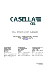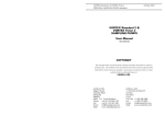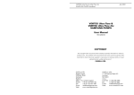
1
Wind Direction 6.3 WIND SPEED & DIRECTION INDICATORS User Manual WIND SPEED & DIRECTION INDICATORS User Manual November 2002 Order List When ordering from this list, please quote the catalogue reference number. 178031C Anemometer standard 178032C Anemometer standard + Heater 178033C Anemometer standard + Conduit 178034C Anemometer standard + Heater + Conduit 178035C Windvane standard 178036C Windvane + Heater 178037C Windvane + Conduit 178038C Windvane + Heater + Conduit 178050B Sensor Interface Module ANEMOMETER & WINDVANE Wind Speed & Direction Sensors User Handbook HB 3276-03 Each sensor is supplied complete with a 01-178015A Mounting Bracket. COPYRIGHT The copyright in this document which contains proprietary information is vested in CASELLA CEL LIMITED. The contents of this document must not be used for purposes other than that for which it has been supplied or reproduced or disclosed wholly or in part without the prior written permission of CASELLA CEL LIMITED ALTERATION WITHOUT NOTICE Please note that the contents of this manual may be subject to alteration without notice. Page 16 of 16 CASELLA CEL Regent House Wolseley Road Kempston Bedford, MK42 7JY U.K. Phone: +44 (0) 1234 844 100 Fax: +44 (0) 1234 841 490 E-mail [email protected] Web: www.casellacel.com CASELLA CEL 17 Old Nashua Road #15 Amherst NH 03031 U.S.A. Toll Free: +1 800 366 2966 Fax: +1 603 672 8053 E-mail: [email protected] Web: www.casellausa.com WIND SPEED & DIRECTION INDICATORS User Manual Contents CONTENTS . . . . . . . . . . . . . . . . PAGE WIND SPEED & DIRECTION INDICATORS User Manual Maintenance 6. MAINTENANCE 3 6.1 Routine Care . . . . . . . . . . . . . 4 Cleaning may be carried out using a soft damp cloth. Solvents or other Anemometer Specifications . . . . . . . . . . . . . . . . 5 1. INTRODUCTION . . . . . . . . . . . . . . . . . . . . . . . . . . 2. ANEMOMETER - WIND SPEED SENSOR cleaning products should not be used. 2.1 Apart from cleaning, no other regular maintenance is required, as the number 3. WINDVANE - WIND DIRECTION SENSOR. . . . . . . . . . . . . 6 . . . . . . . . . . . . . . . . . 7 of moving parts is so few and the bearings on the main spindle are sealed against dust etc. 3.1 Windvane Specifications. 3.2 Setting Up for Highest Accuracy . . . . . . . . . . . . . 8 If the average wind speed is low and weather conditions moderate it is 3.3 RS 232 / NMEA Record Output Format . . . . . . . . . . 8 estimated that six years life can be expected from the bearings. With a higher than average wind velocity and a bad exposure, for example near the 4. MECHANICAL INSTALLATION . . . . . . . . . . . . . . . . . . . 10 sea, then 4 to 5 years might be expected. At the end of this time it is recommended that the bearings be replaced with new ones. Consult Casella 4.1 The Site 4.2 The Mast . . . . . . . . . . . . . . . . . . . . . . . . . . 10 CEL Service Department. . . . . . . . . . . . . . . . . . . . . . . . . . 10 6.2 5. SENSOR INTERFACE MODULE Service . . . . . . . . . . . . . . . . . . 11 We recommend factory service by technicians trained and equipped to repair 5.1 Connection . . . . . . . . . . . . . . . . . . . . . . . . 11 5.2 Interface Specifications your instrumentation. . . . . . . . . . . . . . . . . . . 13 Casella CELs in house service department offers a comprehensive range of 6. MAINTENANCE . . . . . . . . . . . . . . . . . . . . . . . . . . 15 repair and calibration services, designed to effect a fast and efficient back-up for all our products. The Service Department is operated under the scope of 6.1 Routine Care . . . . . . . . . . . . . . . . . . . . . . . . 15 our BSI registration for products manufactured by us. We will however, 6.2 Service . . . . . . . . . . . . . . . . . . . . . . . . . . . 15 undertake the repair of other manufacturers equipment. 6.3 Order List. . . . . . . . . . . . . . . . . . . . . . . . . . 16 For further information please contact the service department at our Bedford headquarters. We will be happy to provide quotations for individual repairs or provide annual maintenance under contract. Should you wish factory repair assistance, send your equipment in a package equivalent to the original packaging. Insure to full value and ship pre-paid. Include a letter giving full details with your packing list. Send to: CASELLA CEL LIMITED (Service Department) Regent House Wolseley Road Kempston Bedford MK42 7JY United Kingdom If purchased outside of the United Kingdom, please return to your distributor. Page 2 of 16 Page 15 of 16 Sensor Interface WIND SPEED & DIRECTION INDICATORS User Manual Standard Interfacing RS 232: WIND SPEED & DIRECTION INDICATORS User Manual 1. ±9 V, 4800 baud, Introduction INTRODUCTION Performance and reliability are the key characteristics of these wind speed 8 data 1 stop bit, no parity, and direction sensors from Casella CEL. as per wind direction sensor, Ω output load 3 k RS 485 / RS 422: minimum. Competitively priced for OEM users, these high quality sensors are housed Differential output, within compact units that can be used in conjunction with each other via a 5 V no load, wind sensor interface module. Both meet Meteorological and WMO 1.5 V minimum (RS 485), requirements. Harsh environmental conditions present no problem to the 2 V minimum (RS 422). units - theyre manufactured from anodised aluminium. Once connected, operate the monitoring system as decribed in the relevant The Casella Anemometer and Windvane are professional sensors intended to system operating instructions. provide reliable and accurate measurement of wind speed and direction, combining traditional Casella quality with modern electronics. They have been developed to offer very smooth and reliable mechanical operation with a minimum of maintenance. The rotational speed of the Anemometer is monitored using a non-contacting design that provides an output directly proportional to wind speeds up to 75 m/sec. The output is suitable for feeding monitoring systems such as the Casella Automatic Weather Station. The Windvane incorporates the very latest technology, using a giant magneto resistive (GMR) sensor to offer accurate and frictionless sensing. It has an electrical output proportional to the direction of the wind. The output, with no deadband at north, is also suitable for feeding monitoring systems such as the Casella Automatic Weather Station. In addition, an NMEA serial output can be made available from the Windvane containing both wind direction and wind speed information updated four times per second. When used with the Sensor Interface module, reliable long distance communications can be provided. Versions of both sensors are available with heaters, with 2.55 m of conduit and with heater plus conduit. Page 14 of 16 Page 3 of 16 WIND SPEED & DIRECTION INDICATORS User Manual Wind Speed 2. WIND SPEED & DIRECTION INDICATORS User Manual ANEMOMETER - WIND SPEED SENSOR 134 mm The sensitive anemometer is based upon a three-cup Sensor Interface 10 Direction Out: 0 - 1.8 V 11 Signal Ground 12 Speed Out: 0 - 2 V rotor design. An infra-red Table 4: SKT4 - Instrument Power light source and optical from 0 to 5 V per revolution. The frequency of the pulses 135 mm sensor provide 20 pulses 01-178015A Bracket is directly proportional to the wind speed. Figure 1 shows the general arrangement of the 5 mm diameter stud 49 mm follows. 00052 Signal Wiring: +V In (6 - 28 V) Red 0V Blue Yellow O/P Pulse Yel/Grn Screen Figure 1: Anemometer wind speed sensor 178031C Anemometer with 4.5 m cable, 178032C Anemometer plus heater and two 4.5 m cables, 178033C Anemometer with 3.25 m cable in a 2.55 m reinforced conduit, 178034C +V in (6 - 28 V) 2 Power Ground 3 Shield Ground 2: Twisted pair wires are preferred to connect the signal outputs of the Interface Module with other equipment. Connect one wire of each pair to signal ground and carry the signal via the other wire of the pair. sensor. additional features as Application 1 Notes 1: Shield Ground should be connected to Power Ground at the instruments power supply. standard wind speed Versions are available with Pin Number 3: Use comms ground as the return signal for RS 232 output or as the common signal for RS 422/RS 485 connection.. 5.2 Interface Specifications General Supply voltage: Power consumption: 12 mA approx. excluding loop currents and sensor loads. Anemometer plus heater and two 3.25 m cables in 2.55 m reinforced conduits. 6 - 28 V DC. 4 - 20 mA Loop Only: Speed and Direction The main casing of the anemometer wind speed sensor has an M5 x 18 mm Output compliance: stud that can be used for fixing it to the mast top or to the bracket supplied Maximum permissible load: (Supply voltage - 1.5 V) minimum. Depends on supply voltage, Ω at 6 V, Ω at 12 V, 1000 Ω at 24 V, 1200 Ω at 28 V. for alternative mounting arrangements. 180 470 All sensors are delivered as standard with a mast Mounting Bracket with pre-drilled Ø 5.1 mm mounting holes for the sensors. Whatever screwed adapter or flange is employed at the junction between anemometer and mast Safety current limit: 27 mA. or bracket, a locknut must be used for full security. The standard model has a single gland and connecting cable with wires colour coded as shown in Figure DC Output Voltages Only 1. The models supplied with a heater have an additional gland and connecting Ω. Output impedance: 470 Wind speed output: 0 - 2 V DC for 0 - 75 m/s wind speed. cable for the heater supply. This has connectors coded as shown in Figure 2. Wind direction output: 0 - 1.8 V DC for o 0 - 359 Page 4 of 16 wind direction. Page 13 of 16 WIND SPEED & DIRECTION INDICATORS User Manual Sensor Interface WIND SPEED & DIRECTION INDICATORS User Manual Wind Speed The following tables list connections to the four sockets in the 178050B Sensor Interface Module. Table 1: SKT1 - Wind Speed Pin Number Application Colour 1 Shield Ground 2 Signal Ground - 3 Speed In Yellow 4 +Vin (6 - 28V) Red 5 Signal Ground Blue 6 Shield Ground Yellow / Green Heater Wiring: Brown 24 V Blue 0V Yel/Grn Screen - Table 2: SKT2 - Wind Direction Signal Wiring: Red +V In (6 - 28 V) Blue 0V Yellow O/P Pulse Yel/Grn Screen 01071 Figure 2: Connections for anemometer versions with heaters 2.1 Anemometer Specifications Transducer type: Optical interrupter Maximum wind speed: 75 m/s Starting velocity: Typically 0.3 m/s Pin Number Application Colour 1 NMEA Output Green 2 Signal Ground - 3 Direction In Yellow 4 Signal Ground White Pulses/revolution: 20 5 +V in (6 - 28 V) Red Non-linearity: <±0.6% 6 Power Ground Black 7 Shield Ground Yellow / Green 8 Speed In Blue Table 3: SKT3 - Output Pin Number 3.5 m/s Time constant: Typically <0.5 s Output calibration: 12.75 Hz/m/s Resolution: 7.84 cm Output signal: 0 - 5 V pulses Accuracy: Direction Out: 4 - 20 mA 2 Signal Ground 3 Speed Out: 4 - 20 mA 4 Signal Ground 5 RS 485 Channel B 6 Comms Ground 7 RS 485 Channel A 8 RS 232 Out 9 Shield Ground ±0.3 m/s below 3 m/s ±1% over 3 m/s Supply voltage: 6 to 28 V DC Power consumption: 3 mA Stabilisation time: <1 s from power up Operating temperature: -20 to +70 C Heater option: 24 V DC / AC, 100 Connecting cable; 4.5 m without conduit o Ω 6 W 3.25 m with conduit Application 1 Page 12 of 16 Distance constant: Conduit: 2.55 m Page 5 of 16 WIND SPEED & DIRECTION INDICATORS User Manual Wind Direction 3. WINDVANE - WIND DIRECTION SENSOR 144 mm The Windvane is a small WIND SPEED & DIRECTION INDICATORS User Manual Sensor Interface 5. SENSOR INTERFACE MODULE 5.1 Connection lightweight GMR design that offers a rapid response The Sensor Interface Module converts standard sensor outputs into formats to changes in wind suitable for long distance transmission (4 - 20 mA, RS 232, RS 485). 148 mm direction. The analog output changes from 0 to 1.8 V as the wind direction changes o from 0 to 359 . Separate 0 - 2 V and 0 - 1.8 V voltage outputs are also available for the wind 01-178015A Bracket speed and wind direction sensors. These can be adjusted, but it should be noted that doing so will also affect the calibration of the 4 - 20 mA loop outputs. An NMEA output enables The four multi-turn potentiometers on the printed circuit board have the direct connection of sensors to the Casella Multimet display system. When the 49 mm 5 mm diameter stud sensors are connected together as described in Chapter 5, the digital output message will contain both speed and direction data. This output provides reliable 00054 long distance digital transmission when used with the sensor interface module. Signal Wiring: +V In (6 - 28 V) Red Black 0 V Speed I/P Blue Green NMEA Serial O/P Yellow Direction O/P White 0 V Signal Yel/Grn Screen following functions. R41 set 4 mA level on 4 - 20 mA output (wind direction), R24 set 4 mA level on 4 - 20 mA output (wind speed), R32 set 20 mA level on 4 - 20 mA output OR set DC output voltage span (wind direction), R2 set 20 mA level on 4 - 20 mA output OR set DC output voltage span (wind speed). Figure 3: Wind-vane wind direction sensor Figure 3 shows the general arrangement of the standard wind direction 178031C 178032C 178033C 178034C 178035C 178036C 178037C 178038C sensor. Versions are available with additional features as follows. 178035C Windvane with 4.5 m cable, 178036C Windvane plus heater and two 4.5 m cables, 178037C Windvane with 3.25 m cable in a 2.55 m 0 - 5 V Pulse Signals SKT3 Sensor Outputs SKT4 Power reinforced conduit, 178038C Windvane plus heater and two 3.25 m cables in 2.55 m reinforced conduits. Sensor Interface Module 178050B The main casing of the Windvane has an M5 x 18 mm stud that can be used 0 - 5 V NMEA Serial 0 - 1.8 V Analog Power NMEA RS 232 RS 485/422 Speed Direction Ground 6 - 28 V DC 10 m Distance 10 m Distance 12 km Distance 4 - 20 mA 4 - 20 mA Return for fixing it to the mast top or to the bracket supplied for alternative mounting arrangements. All sensors are delivered as standard with a mast Mounting Bracket with pre-drilled Ø 5.1 mm mounting holes for the sensors. Whatever screwed adapter or flange is employed at the junction between windvane and mast or bracket, a locknut must be used for full security. The standard model has a single gland and connecting cable with wires colour coded as shown in Figure 4. SKT1 Wind Speed Sensor 2 x 24 V 12 W Heater Power SKT2 Wind Direction Sensor 00056 Figure 5: Connections for the anemometer and windvane Figure 5 illustrates the connection possibities for the various versions of the anemometer and windvane sensors. Connect as appropriate to your system. Page 6 of 16 Page 11 of 16 Installation WIND SPEED & DIRECTION INDICATORS User Manual 4. MECHANICAL INSTALLATION 4.1 The Site WIND SPEED & DIRECTION INDICATORS User Manual Wind Direction A suitable site must be chosen for the sensors that is free from turbulence caused by trees, buildings, hills etc. The site should not be sheltered so that the sensors do not record the true wind conditions. Neither should the site be unduly exposed in a position such as on the crest of a steep hill where more than the average wind velocity is encountered. In particular, it should be noted that a roof does not provide suitable 01070 exposure unless the instruments are mounted well above it. For example, a pitched roof produces strong upward air movement, whose strength varies Figure 4: Connections for Wind-vane versions with heaters with the direction of wind relative to the roof angle. The ideal mounting is a tower, mast or pole about 10 to 15 meters above the Signal Wiring: Red +V In (6 - 28 V) Black 0 V Blue Speed I/P Green NMEA Serial O/P Yellow Direction O/P White 0 V Signal Yel/Grn Screen Heater Wiring: Brown 24 V Blue 0V Yel/Grn Screen 3.1 Windvane Specifications mean ground level. This should be even higher if the ground is obstructed by trees buildings etc. Transducer type: GMR solid state system with microcontroller Make sure the Windvane is correctly oriented towards north ! Use the two small recess markers in the base plate and the N marker on the instrument case to orient the Windvane towards north. 4.2 The Mast Maximum wind speed: 75 m/s Resolution: 1 Accuracy: <±2 o o o Aligning threshold: <0.8 m/s for a 10 Damping ratio: 0.25 Distance constant: Typically 3.0 m offset Undamped natural wavelength: 2.2 m When deciding on the type of mast to erect, the following points should be Repeatability; 0.5% FSD considered. Electrical angle: 0 to 359 Nominal output signal: 0 to 1.8 V DC for 0 to 359 ¤ Restrict access to the mast to avoid interference and vandalism. ¤ Use adequate guy wires to stop vibration, particularly of the top section. o no deadband at North o representing a 1 s rolling average updated 5 times per second NMEA serial output: When anemometer is connected, 0 to 5 V level data containing both ¤ Sometimes a mast may be shared with another user who has some direction and speed information other requirement than meteorology. updated 4 times per second Supply voltage: 6 to 28 V DC Power consumption: 3 mA Stabilisation time: <1 s from power up Operating temperature: -20 to +70 C Heater option: 24 V DC / AC, 100 Connecting cable; 4.5 m without conduit o Ω 6 W 3.25 m with conduit Note *: The design of this sensor does not allow electrical adjustment. Where the greatest accuracy is not demanded (better than ±2o), these sensors can be interchanged. However where higher accuracy is required, the setting up procedure given in Section 3.2 can be followed. Page 10 of 16 Page 7 of 16 WIND SPEED & DIRECTION INDICATORS User Manual Wind Direction Conduit: 2.55 m Two small recesses in the base plate and an N marker on the instrument case identify the position for north. 3.2 WIND SPEED & DIRECTION INDICATORS User Manual 0 = Uncalibrated. 1 = Calibrated, 2 = Calibrated since power on. Wind Direction Example WSD records: Setting Up for Highest Accuracy The design of this sensor does not allow for electrical adjustment. Where the o greatest accuracy is not demanded (better than ±2 ), these sensors can be WSD 125,34.5,0 if never calibrated, WSD 348,102.,1 if using last calibration stored in E2rom, WSD 002,07.8,2 if has been calibrated since powered on. Every 250 ms the following NMEA record is output. interchanged. However where higher accuracy is required, an offset, $MHWAS,ddd,w,nnnn,N multiplier and voltage per degree can be determined for the sensor as where: 21 characters output (inc space, commas and CR/LF). described here. $ = Start of all NMEA marine standard messages ddd = 1. Rotate the windvane head until it gives the lowest direction (yellow) output reading (for example +0.01 V). w = o 2. Rotate the head to give the highest reading (for example 1.785 V). 3. Subtract the lowest reading from the highest to obtain the span. For example 1.785 - 0.01 = 1.775 V o Divide the span by the 359 For example 5. 6. swept arc to obtain the voltage / degree. o 1.775 / 359 = 0.00495 V/ o o = 4.95 mV/ 00.0 - 99.9 or 100. - 999. knots wind speed. N = Units knots Example $MHWAS records: $MHWAS,007,L,35.4,N $MHWAS,179,R,115.,N The data output sequence is as follows. Similarly, divide the arc by the span to obtain the multiplier. Record Type Time (mS) For example WSD 359 / 1.775 = 202.25 o Obtain the offset by subtracting the lowest (0 ) output from 0 V For example $MHWAS The example gives the following results: 4.95 mV / Multiplier: 202.25 Offset: -0.01 V. 0 ms, 0 ms will be same data as WSD 0 ms, except the units are changed, 0 - 0.01 = -0.01 V Reading: is always shown as Right.) nnnn = (i.e just change the sign). 3.3 L/R Left/Right of 0 degree position. (Note that 180 This output indicates the direction of 0 , north. 4. 000 - 180 Degrees left or right from 0 degree direction. o RS 232 / NMEA Record Output Format $MHWAS 250 ms, WSD 500 ms, $MHWAS $MHWAS 750 ms, WSD 1000 ms, $MHWAS 1000 ms will be same data as WSD 100 ms, except the units are changed, $MHWAS Each wind direction and speed output is the average of the last 4 x 250 ms 500 ms will be same data as WSD 500 ms, except the units are changed, 1250 ms, Etc. readings, i.e. a 1 second average over the last second. This is calculated every 250 ms and is followed by a carriage return and newline character. Every 500 ms the following NMEA type record is output. WSD ddd,ssss,c where: 16 characters output (inc space, commas and CR/LF). ddd = 000"-359" Direction degrees. ssss = c = Page 8 of 16 Therefore, every 250 ms, either a single line or 2 record lines are output. These are output at 4800 baud 8 data 1 stop no parity with NO handshaking. The NMEA output of this instrument provides signals between 0 V and +5 V. This is compatible with most RS 232 computer inputs - but is not guaranteed. 00.0"-99.9" or 100. to 999. wind speed in m/s. For compatibility with all RS 232 computer inputs, use the RS 232 output The maximum that can be displayed is approx 159. from the Interface Module. 0",1" or 2". Page 9 of 16