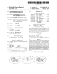
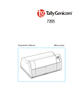
1
Drift Chamber
Control and Readout System
Technical Description
Experimental Particle Physics
Department of Physics
Humboldt University Berlin
Olf Epler - August 2006
1
2
Contents
1 Introduction
3
2 Drift Chamber Hardware
2.1 Gas System . . . . . . . . . . . . . . .
2.2 Drift Tubes and Frontend Electronics
2.3 Trigger System . . . . . . . . . . . . .
2.4 TDC Readout System . . . . . . . . .
.
.
.
.
.
.
.
.
.
.
.
.
.
.
.
.
.
.
.
.
.
.
.
.
.
.
.
.
.
.
.
.
.
.
.
.
.
.
.
.
.
.
.
.
.
.
.
.
.
.
.
.
.
.
.
.
.
.
.
.
5
5
6
8
11
3 Drift Chamber Software
3.1 Overview . . . . . . . . . . .
3.2 HP-RT device driver . . . . .
3.3 Main Program . . . . . . . .
3.4 VME library - vme lib . . . .
3.5 ODB library - odb lib . . . .
3.6 State and Event Log Interface
3.7 Event Display . . . . . . . . .
.
.
.
.
.
.
.
.
.
.
.
.
.
.
.
.
.
.
.
.
.
.
.
.
.
.
.
.
.
.
.
.
.
.
.
.
.
.
.
.
.
.
.
.
.
.
.
.
.
.
.
.
.
.
.
.
.
.
.
.
.
.
.
.
.
.
.
.
.
.
.
.
.
.
.
.
.
.
.
.
.
.
.
.
.
.
.
.
.
.
.
.
.
.
.
.
.
.
.
.
.
.
.
.
.
13
13
14
16
19
20
20
20
.
.
.
.
.
.
.
.
.
.
.
.
.
.
.
.
.
.
.
.
.
.
.
.
.
.
.
.
.
.
.
.
.
.
.
4 Conclusion and Outlook
21
A
A.1 Channel Map and Geometry . . . . . . . . . . . . . . . . . . . . .
A.2 TDC Readout Data Format . . . . . . . . . . . . . . . . . . . . .
A.3 VME Electronics . . . . . . . . . . . . . . . . . . . . . . . . . . .
23
23
24
25
B.1 VME Module Parameters . . . . . . . . . . . . . . . . . . . . . .
B.2 IPC Schemes . . . . . . . . . . . . . . . . . . . . . . . . . . . . .
27
27
28
B
C Drift Chamber Users Manual
C.1 Common Remarks . . . . . .
C.2 Global Parameters . . . . . .
C.3 Program Parameters . . . . .
C.3.1 File / Table - Copy . .
C.3.2 Raw Data Transfer . .
C.3.3 Readout Control . . .
C.4 Event Display . . . . . . . . .
.
.
.
.
.
.
.
D ODBC Application Interface
.
.
.
.
.
.
.
.
.
.
.
.
.
.
.
.
.
.
.
.
.
.
.
.
.
.
.
.
.
.
.
.
.
.
.
.
.
.
.
.
.
.
.
.
.
.
.
.
.
.
.
.
.
.
.
.
.
.
.
.
.
.
.
.
.
.
.
.
.
.
.
.
.
.
.
.
.
.
.
.
.
.
.
.
.
.
.
.
.
.
.
.
.
.
.
.
.
.
.
.
.
.
.
.
.
.
.
.
.
.
.
.
.
.
.
.
.
.
.
.
.
.
.
.
.
.
.
.
.
.
.
.
.
31
31
31
32
32
33
34
36
39
1
2
Chapter 1
Introduction
This documentation is focused on technical aspects - hardware and software - of
a drift chamber developed and build up in cooperation between DESY-Zeuthen
and the physics department of the Humboldt University Berlin.
First calibrations were done in 2005 with a meanwhile changed release and
publicated in [01].
It is now possible to read out all 72 drift tube channels because the formerly
used four 16 channel LeCroy TDCs 1176 are replaced against one 128 channel
TDC CAEN V767.
Furthermore an adapted VME trigger system is now in use.
Important software parts are rewritten and additional features integrated.
Details are documented in the DRC Users Manual attached to this documentation.
3
4
CHAPTER 1. INTRODUCTION
Figure 1.1: Drift Chamber
Chapter 2
Drift Chamber Hardware
2.1
Gas System
All 72 drift tubes are coupled in series with a gas bottle equipped with gas
flow and pressure regulators. The chamber gas is a mixture of 80% Ar [gain
part] and 20% CO2 [quench part]. The gas pressure must be high enough to
compensate the small gas leakage and is adjustable with a flow meter regulator.
The indication of a proper gas pressure and consumption is a bubble frequency
around 1Hz at the oil filled gas flow controller. A gas pressure of around 1bar
corresponds to approximatly 25 - 30 units at the flow meter scale.
It is important to fill the drift tubes at least one hour before the anode high
voltage is turned on!
If the chamber was not used for longer time the gas system should switched on
around 2 - 3 hours before the measurment starts.
Figure 2.1: Gas Regulator and Flow Meter
5
Figure 2.2: Gas Flow Controller
6
2.2
CHAPTER 2. DRIFT CHAMBER HARDWARE
Drift Tubes and Frontend Electronics
The drift tubes and also the frontend electronics were designed for high energy
experiments at CERN (ATLAS) and DESY (HERA-B). Details are publicated
in several papers - only a selection is [02],[03],[04].
Each of the three drift chamber sections includes 24 drift tubes - mechanical
mounted in three layers with 8 tubes per layer in a honeycomb construction.
The exact geometrical dimensions are depicted in fig. A.1 ”Channel Map and
Geometry”.
Electrical each section is conducted to a HV plate shown below.
Figure 2.3: HV plate
The HV plates are the ”distributors” for the positive voltage of around 2200
- 2400V. Each inner thin tube wire - the anode - is connected to this plate.
The tube wall is grounded - so that an electrical field as function of the radial
distance from the anode wire is build up between the anode surface a and the
inner surface of the wall b after the high voltage V0 is turned on.
E=
1 V0
r ln(b/a)
(2.1)
Decoupled over a capacity elementary charges - deponized by the drift electrons
on the anode surface - can now as a signal amplified, shaped, and discriminated
with the frontend module ASD-8. Each ASD-8 module includes two 8 channel
chips - in summary 16 channels per board.
Depicted in fig. A.1 ”Channel Map and Geometry” the left 12 anodes and the
rigth 12 are coupled with one board respectivly.
2.2. DRIFT TUBES AND FRONTEND ELECTRONICS
7
Figure 2.4: ASD-8 boards
The ASD-8 outputs are connected over shielded flat signal cables with level
converter modules - ASD-8-ECL-Translator (A.3) - placed in a VME crate.
The level converter outputs are standard ECL (emitter coupled logic) signals
and directly connected with TDC input channels.
Since the hardware upgrade end of 2005 a CAEN TDC V767 (A.3) is now in use.
The TDC time resolution is 0.8ns (LSB equivalence). Because only a common
stop emulation run mode is provided, the delayed trigger (common stop) line
is additional connected as reference channel to a TDC input. To allow a delay
fine calibration in this case a second reference channels is also connected. The
sum of both delays (GDU output channel 0x03) is the total hit conversion time
window.
To minimize the signal noise it is necessary to set appropriate thresholds for each
ASD-8 module. This is now possible separatly with fine tune potentiometers for
all 6 ASD-8 boards. The potentiometers are avalaible at the front cover of the
distribution board DIB (A.3). This board contains also a central power supply
for all ASD-8 modules. The positive and negative power voltages are adjustable
with front cover mounted fine tune potentiometers.
The power cables are small shielded flat cables - separated from the signal cables.
8
2.3
CHAPTER 2. DRIFT CHAMBER HARDWARE
Trigger System
The trigger and readout electronics is placed in a VME (versa module euro card)
crate and controlled by a single board computer HP 9000 743 in the left slot of
the crate as shown below.
Figure 2.5: VME based DRC electronics
The VME modules and also the single board computer are connecteded to the
crates data backplane. The VME CPU processes a UNIX system - HP-RT with real time kernel extensions and a number of special VME read and write
functions.
Each time a myon (µ+ or µ− as result of a particle decay in the higher earth
athmosphere -> pion decay) crosses the drift chamber scintillator blocks an initial trigger is generated. Γ-quants - emitted by the build in organic scintillator
plates in UV frequency range and transformed by wavelength shifters - pass the
internal coupled ligth fibers and hit the cathode of a PMT (photo multiplier
tube) Hamamatsu H5783.
Based on the light electrical effect the PMT cathode emits electrons. Accelerated by an electrical field between the cathode, a number of dynodes and the
anode - additional amplified by an avalanche process - the resulting electron
flow is as a short signal puls at the PMT output available.
The three scintillator blocks are mounted above the top drift tube section and
below the lower two sections.
The PMT output signals - discriminated and width shaped with a discriminator
DIS CAEN V258 (A.3) - feed now the inputs of the coincidence unit COC (A.3).
With DIP switches - available at the front cover of this module - the input channels of the COC circuit can be activated (right position) or deactivated. The
9
2.3. TRIGGER SYSTEM
resulting width shaped coincidence output signal COO is the trigger input for
the following shown circuit.
DPL
GDU
ENC
6
WDT
IOR
COC
DIS
7
15
0
A
DLB
DLA
IN
A
OUT
STB
IN
IN
COMM
7
CLK
VTO
IN
STB
D
SVT
SYN
HVT
VET
STB
0
C
TST
SYN
B
8
COO
7
IN
OUT
OUT
OUT
OUT
OUT
COO
OUT
B
DLB
CLR
HVT
D
I
P
WDT
IN
DLA
WDT
MUX
SET
COM
0
INT
RES
0
Figure 2.6: VME Trigger Circuit
0
0
0
10
CHAPTER 2. DRIFT CHAMBER HARDWARE
The high voltage for all PMTs is derived from a control voltage and adjustable
with potentiometers in the range from 0 to 1 V. Based on the coincidence output signal COO, the state of a software controlled veto SVT and the state of a
hardware switched veto HVT all other signal lines are set as depicted below.
ENC
start
stop
7: VTO
read out cycle
6: SVT
5: HVT
4: COO
3: DLB
variable delay B
2: DLA
variable delay A
1: COM
0: INT
min delay:
max delay:
320 ns [160 ns fixed DLA and DLB]
1240 ns
Figure 2.7: VME Trigger Diagram
Core of the trigger circuit is a dual programmable logic unit DPL CAEN V495
(A.3). During the trigger initialization the internal lookup table contents of
the DPL must be programmed. Furthermore the variable delays of the gate
and delay unit GDU must be set. The resulting total delay is the time window
during hits - the TDC channel input pulses - can be converted into digital time
values.
The total delay is adjustable between 320ns and 1240ns and set to 1000ns.
This value has to be set also as equivalent time window and offset parameter in
the TDC configuration.
2.4. TDC READOUT SYSTEM
11
Additional the GDU output lines DLA (channel 0x02) and DLB (channel 0x03)
are connected with two TDC reference input channels (0x0F and 0x1F).
A total delay DLT fine adjustment is therefore in following sequence possible:
1.) compute DLB = T(ch 0x1F) - T(ch 0x0F) - noise measurment
2.) set DLB so that DLT = 2 * DLB
3.) set DLA = DLB
DLA and DLB must be set as equivalent parameters in the GDU configuration.
The programmable GDU multiplexer output can be used to check the settings
with an oscilloscope.
2.4
TDC Readout System
The TDC readout is interrupt controlled by a VME single board computer and
attached to interrupt level 1. A standard VME system has 6 levels.
Additional at each level it is possible to select different interrupt capable modules by an one byte wide interrupt vector.
The used interrupt generator module is an input output register IOR CAEN
V513 (A.3). All 16 channels of the IOR can be set as input or output. In this
case channel 0 is programmed as input - all other channels are outputs. As
depicted in figure 2.6 ”VME Trigger Circuit” channel 0 is connected to the interrupt line INT. Simultaneous to the TDC conversion start, the IOR generates
an interrupt. During the following read out cycle the interrupt is deactivated,
the software controlled veto line SVT is activated and the software signal SIGIO
is send to a suspended readout handler process.
All these command calls are processed inside a device driver module. If the
handler has received this signal, the process can now continue and leave the
sigwait state. Following all run queue modules can now read out and the data
written into a file or IO stream. Finally the veto line SVT is deactivated and
the handler suspends again.
If a veto line is active, no further interrupts can be generated. To avoid interrupts after the detection of the first initial trigger, a further hardware switched
veto line HVT is set by a flip flop circuit as long as the veto line SVT is deactived again. This circuit is also placed in the COC module together with the
coincidence circuit and the PMT power supplys.
12
CHAPTER 2. DRIFT CHAMBER HARDWARE
Chapter 3
Drift Chamber Software
3.1
Overview
As shown in the figure below the control and readout software includes a part
processed on the real time operation system HP-RT and another part on a
LINUX system. Both parts are written in one program text segment so that
mostly all functions are available for each side. Operation system specific parts
are separated by compiler directives or specific loaded from libraries.
LINUX
HP−RT
Database /
VME modules
File system
IPC
Event Display
Analysis−Tools
vme_c
IPC
vme_s
vme_s
vme_c
st_fctl
SIGIO
console
(x)inetd
SIGIO
inetd
console
vme_driv
kernel
kernel
Figure 3.1: Drift Chamber Readout and Control System
Two libraries are linked with the main program.
Both libraries - odb lib -> libiodb.a/libiodb.so and vme lib -> libivme.a/libivme.so
- provide shared used and operation system specific parts.
The main program vme s can process different modes - client from a terminal
console, client in server mode, command server and readout or data handler
13
14
CHAPTER 3. DRIFT CHAMBER SOFTWARE
server. The several server modes are invoked by the (x)inetd super server daemon depend on call parameters set in the (x)inetd configuration for different
ports.
A symbolic link to the main program allows to start the client with different
names from different locations inside the file system.
The server processes perform a connection check for calling hosts which must
explicitly be listed as allowed hosts - except localhost. Furthermore the daemon
server processes change the group and user identification equal to the clients
ID. So a readout queue run state query is allowed but it is not possible to stop
this queue if the UID and GID differs.
Additional to the program parameters there are a number of global parameters
available. Only the global parameters read in by the client are valid for all peer
servers. A detailed description of all available global and program parameters
is given in the drift chambers user manual (C).
In some cases it is possible and necessary to overwrite global with program parameters. Optional the default global parameter file can be replaced by a user
defined file or database table.
To decouple the main program from specific access functionalities the library
odb lib defines functions to allow the exchangeable use of sockets, files and
database tables. Underlying parts of the inter process communication [IPC]
between the data handler service on LINUX side and a state and event log interface is also defined here.
Furthermore a line parser and a line writer allows to read and write configuration and parameter strings from or into streams, files or database tables.
The second library - vme lib - provides the initialization and readout functions
for the VME modules and parts of the IPC system.
A more detailed library description follows in chapter 3.4 and 3.5.
3.2
HP-RT device driver
To provide the asynchronous interrupt service a device driver is linked with
the HP-RT kernel. In summary 8 different handler processes can run in parallel. Therefore each readout handler has an own interrupt service. During the
readout process initialization the appropriate driver is initialized. If the interrupt level between driver and VME module configuration matches, the interrupt
vector is delivered to the driver -> vme init int [vme lib]. Later the handlers
process ID, the VME interrupt module type, the modules VME address, the
address modifier byte and a veto line SVT corresponding output value is delivered by several ioctl calls -> vme set drv [vme lib]. If the interrupt line of the
VME system becomes active the kernel breaks and continues with an interrupt
acknowledge cycle. Underlying kernel functions read out the interrupt level and
vector of the VME interrupt generator module. If level and vector matches,
the drivers internal interrupt service routine [ISR] is processed. The SVT veto
line is set, the VME modules interrupt registers are reset, the interrupt line is
cleared and the ISR sends to the handlers PID the signal SIGIO -> vme dev isr
[vme driv]. The handler process is suspended (sigwait state) until this time.
3.2. HP-RT DEVICE DRIVER
15
Now this process can continue and read out all run queue attached modules. If
this is completed the handler sets the interrupt registers again and deactivates
the SVT veto line -> vme set vto [vme lib]. It’s now possible to repeat the
interrupt cycle at the next valid trigger.
16
3.3
CHAPTER 3. DRIFT CHAMBER SOFTWARE
Main Program
Core of the main program - independent from the run mode - is a finite state
machine [FSM] processed as followed:
sta(n)
out(n)
cmd(n+1)
:=
:=
:=
F(cmd(n), f(sta(n - m)))
F(sta(n - m))
F(out(n), sta(n))
m ǫ 1..N
m ǫ 0..N
sta:
out:
cmd:
FSM state
FSM output
FSM input
To each new state can attached an output function. The return value is the
following input command. The FSM loop ends at failure or if the new state is
equal to the initialization state. To transfer data between attached processes,
an inter process communication system [IPC] is integrated. It is controlled by
the signals SIGUSR1, SIGUSR2, SIGTERM and SIGIO. The general principle
is shown below:
GSM
GSM
DEVCPY
DEVCPY
DSM
DSM
DSM : detach shared memory
S/W
S/W : kill / sigwait
FCC
FCC : optional function call
S/W
FCC
SIGUSR1
SIGUSR2
GSM : get shared memory
attach shared memory
DEVCPY : copy into / from shared memory
Figure 3.2: IPC sheme
To transfer data between process A and process B a shared memory device is
used. This must requested before and released later - it depends on the specific program flow. The initial process - defined as client - attaches this shared
memory device and copies data from the process memory into the shared memory. The peer process - defined as server - is responsible to initialize the shared
memory at least with a process identification number (PID) - typical the servers
own PID. If the client needs a server response, then also the clients PID must
be copied into the shared memory. Because both processes can act as client or
as server a client and a server receiver signal should be defined. If the client or
the server has finished the copy procedure the initial process can now send a
signal to the peer. The suspended peer process can now continue and attach the
shared memory, copy the data into its own process memory and finally detach
the shared memory.
The different IPC schemes are depicted in appendix B.2. The actual run state
3.3. MAIN PROGRAM
17
and other queue informations exist as a copy in each queue owned shared memory. Handler and command servers are invoked from the (x)inetd super server
daemon. Each handler process is responsible for requesting and freeing the
shared memory resources.
18
CHAPTER 3. DRIFT CHAMBER SOFTWARE
To allow a flexible way to read and write configuration data and state informations from or into sockets, files or database tables the library odb lib provides
this functions. This allows to handle sockets and database tables similar to files.
A short description follows in chapter 3.5.
To minimize the dead time of the HP-RT readout cycle it is possible to write
the data into a TCP/IP stream instead of a file. This stream is opened if the
VME system has an attached data handler host at run queue start - set by the
VME DHST parameter - and closed at run queue stop. A mechanism - called
signal driven IO [05] - allows the receiver host to read data from the stream
buffer and to write this data into a new created or already existing output file.
Additional the last n data events can be made available for an event display.
N can be set with the global parameter VME ELOG. The interface for state
and event logging is explained in chapter 3.6. On VME side the module control
and readout functions are defined in a separate library - vme lib. This library
exports the necessary entry point functions and allows the VME module initialization and readout completly independent from the main program. A detailed
description is given in the next chapter.
19
3.4. VME LIBRARY - VME LIB
3.4
VME library - vme lib
To control a wide range of different VME module types only a place holder array
- dev lst - must be delivered to the libraries entry point functions. A linked list
of modules with comparable functionality can now attached to the appropriate
array field.
field number
module type
DMC:
ADC:
TDC:
DIS:
DPL:
GDU:
IOR:
HVM:
0
DMC
1
ADC
2
TDC
3
DIS
4
DPL
5
GDU
6
IOR
7
HVM
direct memory access cards
analog to digital converters
time to digital converters
discriminators
(dual) programmable logic units
gate and delay units
input output registers
high voltage modules
It is therefore possible to initialize several module types from one or different
configurations. Each time a module definition line is parsed the given number of memory blocks is allocated, appended to the appropriate list field and
initialized with the following module parameters as shown in the example below:
[TDC][V767]:
TDC ADR:
TDC ADM:
TDC IVC:
TDC ICP:
TDC CHN:
TDC TRG:
TDC RMD:
TDC RTP:
TDC MTP:
TDC EDG:
TDC WIN:
TDC OFW:
TDC CMD:
1
0x050000
0x39
0x00
ICP DIS
[8FFF8FFF] [0FFF0FFF] [0FFF0FFF] [00000000]
0x1F
COMMON STOP
AQUISITION
RELATIVE
RISE
40
-40
[CMD 00]
module definition line
TDC address
TDC address modifier
TDC interrupt vector
TDC interrupt capability
TDC channel mask
TDC reference channel
TDC run mode
TDC run type
TDC measurment type
TDC hit edge
TDC hit window
TDC hit window offset
TDC command marker
[CMD 00]:
0x1600 0
TDC command
If the configuration line parsing is finished a hardware type check at the given
VME address follows. If this check is successful, then the VME module can
be initialized. Depend on the initialzation return value the necessary module
parameters for the handler control and readout are copied into a global memory
buffer - provided by the main program. If the module initialization is finished
all allocated memory blocks can now released.
20
CHAPTER 3. DRIFT CHAMBER SOFTWARE
Additional the library provides an entry point function to scan the type and
the serial number of all or only one module attached to a VME address ->
vme scn type. Another entry point function is used to read out all modules
listed in a handlers run queue (ADCs, TDCs, ... ) -> vme mod rdo. Already
explained in chapter 3.2. the library exports also the necessary functions for the
interrupt service initialization and some underlying parts of the IPC system ->
devcpy.
3.5
ODB library - odb lib
This library containes a line parser, a line writer, a number of converter functions, a state and event log interface and an open database connectivity (ODBC)
application interface. The ODBC interface and additional the socket access
functions sgets and sputs allow to handle database tables and sockets in the
same way as defined for the standard IO file handling. During the program run
time the appropriate function set is called. With an additional format parameter in dopen it is also possible to create database tables with more then only
one column and different column types. A more detailed description is given in
(D).
3.6
State and Event Log Interface
Optional event data and/or state information can be written in parallel into
a file or a database table. This can be enabled or disabled with the global
paramters VME ELOG for event logs and VME SLOG for state logs.
If an event display runs at the data receiver host, the IPC system - shown in
B.2. - signals each new event. The event display acts here as a server process
and is responsible to create, to initialize and finally to release a shared memory
device.
3.7
Event Display
The event display runs independent from the readout system and presents in
the default online mode each new data event.
Additional it is possible to process raw data files (also the files taken with the
LeCroy TDCs) in offline mode (simulation). In both modes the display process
can be suspended and later continued.
Two types of event counters are available - a relative counter that can be reset
at any time and an absolute counter.
A short program description is given in Appendix C.
Chapter 4
Conclusion and Outlook
With the new drift chamber hardware and software release it is now possible to
do the next step and make it available as a lab experiment for students. Before
this can be done it is necessary to determine the DRC working point again the operation conditions at which the chamber provides the highest detection
probability (optimal anode high voltage versus optimal ASD-8 thresholds).
Because the TDC type was changed, also a new t0 calibration is necessary.
The new state and event log interface allows to use a stable and independent
working event display, the extended IPC system to integrate the data aquisition
control into a more userfriendly environment.
At this place my thank to all who participated in building up and testing the
DRC.
21
22
CHAPTER 4. CONCLUSION AND OUTLOOK
Appendix A
Channel Map and Geometry
ASD8
ASD8
TL
HV−BACKPLANE
L = 2( C )
TR
D=0
2
3
4
6
1
8 11
9 12
5
7 10
383
A.1
D=1
L = 1( B )
MR
383
ML
L = 0 (A )
BR
30
BL
450
drift chamber channel map
TL
TR
D
0x40
0x50
ML
0x20
C
0x40
TDC_CHN = L * 0x20
+ D * 0x10
+ DRT − 1
MR
0x30
BL
BR
B
0x00
ASD−ECL−CNV
0x10
ASD−ECL−CNV
A
0x20 0x00
TDC V767
Figure A.1: Channel Map and Geometry
23
24
APPENDIX A.
A.2
TDC Readout Data Format
VME readout data format
1 x time line
HOUR
QUEUE
MINUTE
SECOND
1 x header line
NUM
TYP
0 1 0
R
A
[EVENT *] HIT NUMBER
IVC
[event *] hit data lines
0
R
CHN
P
F
0 0
R
S
TIME DATA
header line
NUM
TYP
R/A
IVC
: module number
: type number [ 1 = TDC_1176, 2 = TDC_V767 ]
: 0 = relative time measurement, 1 = absolute time measurement [only TDC_V767]
: interrupt vector
data line
0/R
CHN
P/S
F/R
: 0 = data channel, 1 = reference channel [only TDC_V767]
: channel number
: 0 = P [common stop], 1 = S [common start]
: 0 = F [falling edge], 1 = R [rising edge]
Figure A.2: TDC Readout Data Format
25
A.3. VME ELECTRONICS
A.3
1
1
1
1
1
1
4
1
2
1
1
VME Electronics
CPU
HVM
DIS
DPL
GDU
IOR
ENC
TDC
AEC
COC
DIB
Module Typ
VME-CPU HP 9000
High Voltage Module
8 Channel Discriminator
Dual Programmable Logic Unit
8 Channel Gate and Delay Generator
16 Channel Programmable I/O Register
8 Channel NIM-ECL/ECL-NIM Translator
128 Channel General Purpose Multihit TDC
ASD-8-ECL Translator
Coincidence Unit / PMT Control Supply
ASD-8 Distribution Board
Typ
743
VHQ 205L
V258
V495
V486
V513
V538 A
V767
AEC
COC
DIB
Manufacturer
HP
ISEG
CAEN
CAEN
CAEN
CAEN
CAEN
CAEN
DESY-Z EW
HU/DESY-Z EW
HU EW
26
APPENDIX A.
Appendix B
B.1
VME Module Parameters
Each VME module configuration contains common and special parameters. The
module addresses and the modules address modifiers are necessary for each module. The interrupt level and vector must be set for interrupt generator modules
(IOR). For readout modules (ADCs, TDCs, ... ) the interrupt vector value
defines the run queue number shared with an interrupt generator module. An
interrupt controlled readout is only possible if exactly one interrupt generator
module is defined per queue. Optional one or more (maximum 7) readout modules can be attached to a queue. The initialization order is free.
The channel number is only valid for channel providing modules.
A run mode is set module specific and defineded in the structure spc lst [vme m.h].
common parameter
<MOD> ADR
<MOD> ADM
<MOD> INT
<MOD> IVC
<MOD> CHN
<MOD> RMD
description
VME address
VME address modifier
VME interrupt level
VME interrupt vector
module channel number
module run mode
All other parameters are module attached special parameters. The special parameter definitions contains the structure mod lst [vme m.h] - the special parameter settings the structure spc lst [vme m.h].
27
28
B.2
APPENDIX B.
IPC Schemes
HP−RT IPC
STA_STT
CLIENT/SERVER
1. TO_STTH
GSM
STA_STP
HANDLER
STA_IRQ
CLIENT/SERVER
[127.0.0.1]
QUESET
DEVCPY
SEND
2. TO_WAIT
SIGUSR2
GSM
WAIT
SIG
DEVCPY
GSM
DEVCPY
DEVCPY
SIGUSR1
SIGUSR1
SIG
GSM
WAIT
WAIT
DEVCPY
DEVCPY
WAIT
SIG
SIG
SIGUSR2
Figure B.1: HP-RT IPC
WAIT
29
B.2. IPC SCHEMES
LINUX IPC [STA_STT | STA_STP | STA_IRQ]
TO_CHST
[127.0.0.1]
GSM
SEND
GSM
QUESET
1. TO_STTH
2. TO_CHST
SIGUSR2
WAIT
GSM
SIG
DEVCPY
DEVCPY
SIGUSR2
SIG
SIGUSR2
SIG
WAIT
Figure B.2: LINUX IPC
LINUX IPC DATA HANDLER
STA_STT
1. TO_STTH
GSM
STA_STP
[127.0.0.1]
QUESET
DEVCPY
SEND
GSM
2. TO_WAIT
SIGUSR2
GSM
WAIT
SIG
DEVCPY
DEVCPY
SIGUSR1
SIG
SIGUSR1
WAIT
WAIT
SIG
SIGIO
DEVCPY
RDO
RDO
SIGUSR2
SIG
Figure B.3: Data Server IPC
WAIT
30
APPENDIX B.
LINUX IPC EVENT DISPLAY
START
PARENT
GSM
STOP
CHILD
VME DATA HANDLER
CSM
GSM
DEVCPY
WAIT
GSM
DEVCPY
SIGUSR1
SIG
PID ?
SIGUSR2
DISPLAY
EVNCPY
SIG
Figure B.4: Event Display IPC
Appendix C
Drift Chamber Users
Manual
C.1
Common Remarks
The main program is processed in several run modes - depend on call parameters - on two operation systems - HP-RT and LINUX.
The user interface - the client - is typical a symbolic link to the main program
vme s. It is possible to create links with different names and locations in the
file system - for example in $HOME/bin.
The default location of the main program is /usr/local/sbin/vme s,
the default location of the user interface is /usr/local/bin/vme c.
On both operation systems the same program parameter set is available - except
the database functionality at HP-RT side.
C.2
Global Parameters
Only the parameter set read in by the client - the user interface - is valid and
transfered to the clients peer servers.
The default parameter configuration file is /etc/VME/vme.cfg - but also a user
defined configuration can be delivered with the program call:
vme c -g <par glb.cfg> | <”DB:par glb”> -s <par dta.cfg> | <”DB:par dta”>
31
32
APPENDIX C. DRIFT CHAMBER USERS MANUAL
parameter
VME ODBC
VME ODSN
VME ALLW
VME CHST
VME WHST
VME WPRT
VME DHST
VME PDTA
VME RDTA
description
ODBC initialization file
ODBC data source name
hosts allow file
command execution host
WWW server
WWW port
data receiver host
module parameter data
raw data output file
parameter
VME ELOG
VME EDTA
VME SLOG
VME SDTA
VME LOGD
VME PARD
VME PRGD
VME RAWD
description
event log enable/disable
event log file/table
state log enable/disable
state log file/table
log output directory
module parameter directory
program directory
raw data directory
*)
**)
***)
C.3
**)
**)
*)
*)
default value
/etc/odbc.ini
[vme]
/etc/hosts.allow
localhost
localhost
80
localhost
NULL
vme dta.raw
***)
**)
**)
***)
HP-RT
x
x
x
x
x
x
x
default value
DISABLE
vme evn
DISABLE
vme sta
/etc/VME/log/
/etc/VME/par/
/etc/VME/prg/
/etc/VME/raw/
HP-RT
x
x
x
x
x
x
x
x
can or must be set with command parameters -> program parameters
not used in the actual version
must be adapted system specific
Program Parameters
A client call at a terminal console without any additional program parameters
lists all available parameters as an usage information.
Only the parameters without a beginning * character are user parameters!
C.3.1
LINUX
x
x
x
x
x
x
x
x
x
File / Table - Copy
vme c -a <file> | <”database:table”> -w <file> | <”database:table”>
appends the content of a file or database table to an already existing file or table
or creates a new file or table and copies the content.
At HP-RT side only the file copy functionality is available.
A call without the second parameter -w (or wrt) deletes the file or table given
by -a (or app).
To select a database and a table the construct <”database:table”> has to be
set.
All other necessary values are initalized with settings delivered in VME ODBC
and VME ODSN.
LINUX
x
x
x
x
x
x
x
x
C.3. PROGRAM PARAMETERS
C.3.2
33
Raw Data Transfer
vme c -y <source file> -b <destination file>
transfers the content of the source file from host A to host B - given by VME CHST.
34
C.3.3
APPENDIX C. DRIFT CHAMBER USERS MANUAL
Readout Control
All necessary steps to initialize and start a run queue can be done with only
one command call, several module specific calls or module combined calls.
The module initialization order is fixed by an array index defined in vme lib as
listed below.
array index
DMC
DMC[0]
DMC[1]
ADC
ADC[0]
ADC[1]
TDC
TDC[0]
TDC[1]
DIS
DIS[0]
DIS[1]
GDU
GDU[0]
GDU[1]
IOR
IOR[0]
IOR[1]
HVM
HVM[0]
HVM[1]
DMC[7]
ADC[7]
TDC[7]
DIS[7]
GDU[7]
IOR[7]
HVM[7]
The initialization order starts at index 0 (DMC) and ends with 7 (HVM). Only
the allocated and initialized memory blocks - beginning from block 0 - are used
for the finally module initialization.
If the VME module initialization is finished all allocated blocks are now released.
In the following example a module combined initialization is shown.
Trigger Initialization
To initialize the trigger it is necessary to set the variable delay length DLA
and DLB of a gate and delay unit - CAEN V486 - and to program the lookup
tables of a logical unit - CAEN V495.
The parameter configuration file or table is delivered with:
vme c -s vme c trg.cfg or vme c -s ”vme:vme trg”
Each time the VME-CPU has booted or rebooted the trigger initialization is
necessary.
Start Queue
A readout queue includes the initialization of the TDC CAEN V767 and the
IOR CAEN V513. Optional it is possible to change the raw data output file
name.
vme c -s vme c tdc.cfg or vme c -s ”vme:vme tdc”
vme c -s vme c ior.cfg or vme c -s ”vme:vme ior” < -b vme dtb.raw >
As response to a run queue start the state is printed at the clients console:
vme c: irq[0]: run mod[0]: 1 ivc[0]: 0x00
vme c: irq[0]: run mod[0]: 2 ivc[0]: 0x00
C.3. PROGRAM PARAMETERS
35
Stop Queue
A running readout queue can be stopped with
vme c -x <queue> or vme c -x all
or suspended with
vme c -d <msa adr>
and reinitialized with an appropriate start command.
The <msa adr> parameter is the most significant address of the TDC or IOR
and can be listed with a type query call
vme c -t all
If one or all queues are stopped the state is printed at the console:
vme c: irq[0]: stp
State Query
A run state query with
vme c -q <queue> or vme c -q all
prints the same state information for one or all queues as shown above.
Set and Reset the High Voltage
The HV module configuration to switch on the anode high voltage can be delivered with following start command calls:
vme c -s vme c hvm.cfg or vme c -s ”vme:vme hvm” - to set
To shutdown or change the high voltage a different configuration must be used:
vme c -s vme 0 hvm.cfg or vme c -s ”vme:vme h0m” - to shutdown
Optimal values for the high voltage are HVM VLS = 2200 .. 2400.
To switch off the HV this parameter must be 0!
36
C.4
APPENDIX C. DRIFT CHAMBER USERS MANUAL
Event Display
The event display can run different modes - online and offline - and allows simply to switch between both modes. At program start and each time an offline
simulation is finished the program returns into the default online mode.
The GTK+-2.0 based user interface is typical a symbolic link to the server program evn s - so it is possible to create links with different names and locations in
the file system. The default location of the user interface is /usr/local/bin/evn c.
To start the event display simply type in:
evn c -s
The program can be closed with EXIT or Alt-F4.
Independent from the run mode it is possible to stop and continue the event
presentation.
An offline simulation starts if a raw data file is choosen in the file selection window as shown below. During an offline processing the simulation can additional
finished with a right mouse button click -> QUIT.
Furthermore two counters are available. Between the default relative and the
absolute counter can be toggled with the middle mouse button. The use of the
right mouse button resets the relative counter.
37
C.4. EVENT DISPLAY
Figure C.1: Offline File Selector
Figure C.2: Event Display
38
APPENDIX C. DRIFT CHAMBER USERS MANUAL
Appendix D
ODBC Application
Interface
The ODBC (open database connectivity) API library functions
- dopen, dclose, dgets, dputs, and demove are entry point functions to create, to transfer data to and from, and to delete
tables in a SQL database system with the same call conventions and return
values as defined for the ANSI-C stdio functions
- fopen, fclose, fgets, fputs, and remove.
Additional defined dopen C style format parameters can be used and listed at
end.
Requirements for installation and database access :
I.
II.
(My)ODBC and IODBC libraries and includes must be available
all necessary configurations and permissions to connect the database system,
to create or delete tables, and to insert data into a table
Entry Point Functions and Format Parameters
39
40
APPENDIX D. ODBC APPLICATION INTERFACE
FILE * dopen( const char * db tb name, const char * format )
db tb name:
a string construct ”database:table”
the double colon is the delimiter to separate database and table
format:
a format string similar used for the stdio function fopen:
”r”
or ”r+”
to open an existing table for read operations
”w” or ”w+” to create a non existing table with one column type varchar o
to open and clear an already existing table for write operatio
”a” or ”a+” to open an already existing table or to create it new for appe
An optional index parameter i is defined to create more then only one column
and to define different column types:
dopen(”<database>:<table>”, ”a+i[ int index %i string index %20s hex index %x ]”);
navigates into the database and creates a table with following index specifiers and column formats:
int
int index
string index
varchar(20)
int unsigned
hex index
If an index specifier is not set or left free an internal format converter creates this as followed:
IDX
for a table with only one column,
IDX 0, IDX 1, ... for tables with more then only one column
41
int dclose( FILE * dfp )
dfp:
a FILE pointer returned by a dopen call before
The function dclose disconnects from a database system if dfp is a valid pointer
- the return value of a successful dopen call - and frees the internal memory
allocated by dopen before.
dclose returns always 0.
char * dgets( char * buf, int size, FILE * dfp )
buf:
size:
dfp:
a pointer to a delivered buffer
the buffer size
a FILE pointer returned by a dopen call before
dgets reads one row from a table,
copies the ASCII converted and space separeted values into the buffer and
increments an internal read pointer.
If a compare string was set before with
strcpy(ofp->sql cps, ”<index specifier>=<specifier>”);
dgets reads out only the matching parts.
dgets returns the pointer to buf as long as the last row isn’t reached or else NULL.
int dputs( char * buf, FILE * dfp )
buf:
dfp:
a pointer to a delivered buffer
a FILE pointer returned by a dopen call before
dputs inserts the - column type converted - value(s) from the buffer into a table missing values are written as null equivalents.
dputs returns 0 at success or else EOF.
int demove( const char * db tb name )
db tb name:
a string construct ”database:table”
demove connects the database system and navigates into the database,
removes the table - if the table exist and the necessary grants are present disconnects from the database system, and
returns 0 at success or else EOF.
format parameter
%s
%<n>s
%c
%i
%x
%f
%d
%t
SQL type
varchar(SQS MAX)
varchar(<n>)
char
int
int unsigned
double
date
time
( SQS MAX = 254 )
( n[ 1..254 ] )
42
APPENDIX D. ODBC APPLICATION INTERFACE
Bibliography
[1] Siddeequah Azmi, Calibration of Cosmic Ray Tracker, (HU Dep. of Physics
June 2005)
[2] The ATLAS Myon Collaboration, ATLAS muon spectrometer technical design report, (CERN/LHCC 117-150, May 1997)
[3] HERA-B Outer Tracker Group, The Front-End Electronics of the HERA-B
Outer Tracker Detector, (DESY April 2002)
[4] H.-U. Kirst, H. Kolanoski, V. Suvorov, F. Tonisch, S. Vassiliev, M. Walter,
Test Results of a Multi-Layer Board Based on the ASD-8B Chip, (DESY
August 1995)
[5] W. Richard Stevens, UNIX Network Programming (Prentice Hall PTR,
1998)
43