1
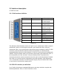
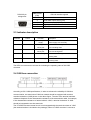
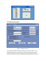
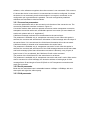
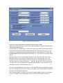
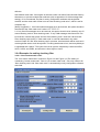
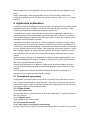
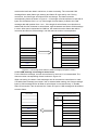
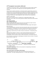
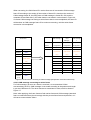
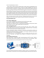
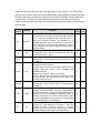
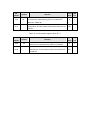
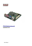
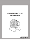
UT-2505 Converter manual
1.1
UT-2505 intelligent protocol converter can quickly connect RS-232/485 communication
device to CAN-bus field bus.
The converter supports RS-232/RS-485 with the communication speed range of
1200~115200bps and CAN-bus communication speed range of 5Kbps~1Mbps. The
converter supports three data conversion modes: transparent conversion, transparent
conversion with flag and Modbus protocol conversion; it also supports Modbus RTU
protocol. UT-2505 converter is equipped with configuration software, and user can flexibly
set UT-2505 converter operation parameters.
Applications:
Mine remote communication
Intelligent buildings, public broadcasting system
Security and fire network
Industrial communication network
Railway device network
Features:
Duplex data communication between CAN-bus and RS-232/RS-485;
Supporting CAN2.0A and CAN2.0B protocol, complying with ISO/DIS 11898
specification;
Integrated one-way CAN-bus communication interface, supporting user-defined
communication baud rate;
Integrated one-way 3-wire RS-232 communication interface, and communication rate
could be set within the range of 1200~115200bps;
Supports three data conversion modes: transparent conversion, transparent conversion
with mark, and Modbus protocol conversion;
Operating temperature: -40℃ ~ +85℃.
2.1 Appearance
2.2 Interface description
UT-2505 converter
2.2.1 CAN interface definition
Pin No.
Name
Description
1
CANH
Connection terminal
of CANH signal
2
CANL
Connection terminal
of CANL signal
3
RES-
Terminal 1 of CAN
matching resistor
4
RES+
Terminal 2 of CAN
matching resistor
5
RESET
6
GND
Ground
7
GND
Ground
8
SET
Set signal
9
VIN
Power supply input +
10
GND
Power supply input -
Reset
Figure 2.2
The definition of CAN interface is shown in Figure 2.2: pin1 marked with “CANH”, and pin2
marked with “CANL” are CAN signal connectors, pin3 marked with “Res-“ and pin4
marked with “Res+” are connected with CAN network terminal resistance. When UT-2505
converter is used as CAN-bus network terminal, the resistance of 120Ω should be
connected between two pins; if the resistance of 120Ω is not connected, pin5 marked with
“RESET” and pin6 marked “GND” are conversion reset signals; pin8 marked with “SET” is
the configuration pin of the converter. If the pin is floating, when it is powered, the
converter will enter the normal conversion mode; if the pin is connected with pin7 marked
with “GND”, the converter enters configuration mode when powered. Pin9 marked with
“Vin” is connected to external +9V~30V DC power supply, and pin10 marked with “GND”
is connected to external power supply ground.
2.2.2 RS-232 interface pin definition
For UT-2505, RS-232 port is standard DB9 socket, and the pin definition complies with
RS-232 specification. Here, a 3-wire connection is used,
RS-232C pin
assignment
DB9 Female
(PIN)
RS-232 interface signals
1
Protective earth
2
Serial data output SOUT(TXD)
3
Serial data input SIN(RXD)
5
Signal ground GND
4, 6, 7, 8, 9
Vacant
2.3 Indicator description
Indicator
Colour
Function
PWR
Red
Operation power
supply
232TX
232RX
Green
Yellow
Green
When the indicator is on, the converter
power supply runs normally.
Sending via
The indicator flashing means the series
series port
port is sending data.
Receiving via
series port
CANTX
Description
CAN sending
The indicator flashing means the series
port is receiving data.
The indicator flashing means the CAN is
sending data.
CANRX
Yellow
CAN receiving
The indicator flashing means the CAN is
receiving data.
The LEDs on converter are all used for indicating the operating state of UN-2505
converter.
2.4 CAN bus connection
According to ISO 11898 specifications, in order to enhance the reliability of CAN-bus
communication, two terminals of CAN-bus network should be equipped with terminal
matched resistance (120Ω) shown in the above figure. The size of the terminal matched
resistance depends on the characteristic resistance of the transmission cable, for example,
if the characteristic resistance of twisted cable is 120Ω, a terminal resistance of 120Ω
should be integrated to two bus terminals.
The UT-2505 converter internal circuit is not integrated with the terminal resistor of 120Ω
(the terminal resistor is included to the package). When UT-2505 converter is used as a
terminal device, the user can connect terminal resistor of 120Ω in UT-2505 converter CAN
interface between pin3 “Res-“and pin4 “Res+”.
For UT-2505, there are two installation methods: DIN rail installation and self-stacked
installation.
The twisted cable or shield twisted cable can be used as CAN communication line. If the
communication distance exceeds 1KM, the wire sectional area should be ensured of at
least 1.0mm2. The detail specification should depend on distance and it should be
regularly enlarged with the increasing distance.
3. Configuration instruction
Since there are so many communication parameters in CAN-bus and RS-232 series port,
UT-2505 allows users to make settings by themselves according to actual application
requirements. UT-2505 converter configuration includes the converter conversion mode,
series port parameters, CAN-bus parameters etc. The parameter configuration can be
implemented with configuration software. Before normal operation, the conversion
parameters of UT-2505 should be configured in advance; if it is not configured, the
parameters which are successfully configured will be implemented in UT-2505 converter
(if it has never been configured, the default parameters will be implemented in the
converter).
3.1 Configuration
In order to enter the configuration mode, a special configuration switch——pin8 marked
with “SET” and pin7 marked with “GND” in CAN interface side is used.
After “SET” is grounded and the converter is powered, it will enter “configuration” mode;
when “SET” pin hanging and the converter is powered, it will enter “normal operation”
mode.
The steps of entering configuration are listed below:
1. Connecting the SET and GND of the converter with cable, and power on.
2. Connecting UT-2505 converter and PC with series port line, which is included to the
package.
3. Running configuration software on PC side, selecting corresponding device, opening
series port and setting parameters.
3.2 Software description
Figure 3.1 Configuration interface
The configuration software interface of UT-2505 converter is shown in Figure 3.1. The
configuration software can save and display UT-2505 converter parameters, which are
successfully set at last time. It also can read out the current parameters of UT-2505
converter. Only after converter enters configuration mode, the parameters can be set via
software, or the software recognizes when the converter is not connected. Click connect;
if it shows the device is connected, it is connected and it could be configured; if it shows
the device is not connected, please check whether it is occupied, connected, or the
configuration pin is grounded and is powered. The main configuration parameter
definitions are described in detail as follows.
3.2.1 Conversion parameters
Conversion parameters refer to the conversion rule direction of the conversion etc. The
conversion parameters interface is shown in Figure 3.1.
Conversion modes: there are three optional conversion modes: transparent conversion,
transparent conversion with mark, and Modbus protocol conversion (for more details on
each mode, please refer to “4. Application”).
CAN frame message is allowed to be retransmitted to the series frame:
The parameter is available only in “transparent conversion" mode. When this option is
selected, the converter will add the frame information of CAN message at the first byte of
the series frame. If it is not selected, the CAN frame information will not be converted.
CAN frame identity is allowed to be retransmitted to the series frame:
The parameter is available only in “transparent conversion” mode. After this option is
selected, the converter will add frame ID of the CAN message between series frame data
and frame message (If the frame information conversion is allowed), every 4 bytes, 8
bytes in total. If it is not selected, the CAN frame ID will not be converted.
The position of the CAN frame ID in the series frame is as follows:
The parameter is available only in “transparent conversion with mark” mode. When series
data is converted to a CAN message, the deviation address of starting byte of CAN
message frame ID and length of frame ID (Refer to 4.2 Transparent conversions with
mark) are converted.
3.2.2 Serial parameter
Baud rate: the serial baud rate is selectable between 1200bps~115200bps, with one
start-up bit and eight bits, without parity.
3.2.3 CAN parameter
Figure 3.2 CAN parameter interface
Baud rate: CAN bus baud rate is selectable between 5Kbps~1Mbps.
Frame type: when conversion, there are two CAN message frame types, standard frame
and optional extended frame.
Sending frame ID: available only in “transparent conversion” mode, which means that the
series data is converted to CAN message frame ID value (hex data); note that it is not
available in “transparent conversion with mark” mode, so the sent frame ID is filled with
the data in above series frame. (Refer to the section 3.2.1 The position of CAN ID in series
frame)
[Note]: the frame ID is the actual CAN message ID value (the order from left to right is
form higher byte to lower byte), for example, if the value is “00 00 00 0A" (HEX), the
sending frame ID is 10 (the data should not be shifted as it did in the previous version).
The bytes from left to right are named as
ID0, ID1, ID2 and ID3. The bit sequence is
from high to low, and the capital letters, spacing and character number should be same
with that it is opened or there will be an error.
This item is also related to the “frame type”. If the "standard frame” is selected, the frame
ID is 11bit available and the value range is 0~7FF (HEX). The exceeded part is invalid and
only lower 11bit is taken as effective.
If the “extended frame” is selected, the frame ID is 29bit available and the value range is
0~1F FF FF (HEX). The exceeded part is invalid, and only lower 29bit is taken as
effective.
Self-defined mask code: if this option is selected, users can define CAN controller filter by
themselves, to provide multiple filter methods (refer to appendix A.3 CAN message filter
setting); if it is not selected, the filter is set by configuration software with single-filter
method, and the mask code of filter is set as “filter checking code value”, which is set for
reception only.
[Note]: Suggestion: 1. If all CAN nodes messages are to be received, this option should be
selected and the “filter mask code” value is “FF FF FF FF”.
2. If only fixed ID messages are to be received, this option should not be selected, only fill
actual checking code to “filter checking code”. If only CAN message with frame ID 6 is to
be received, unselect this option and set “filter checking code” value with “00 00 00 06”.
Filter checking code (ACR): if “filter mask code" is set with interrelated, only when
received “frame ID” and “filter checking code” are same, this frame data will be received in
receiving buffer area or it will be rejected. The filling data format is hex, and every 8bit byte
is separated with “Space”. The bytes from left to right are respectively named as ACR0,
ACR1, ACR2, and ACR3, and bit order is from higher to lower.
3.2.4 Examples for setting checking filter
3.2.4.1 “Non-custom mask code”
The “non-custom mask code” is shown in Figure 3.3 and Figure 3.4 (The setting of
unselecting “custom mask code”. Due to “non-custom mask code”, user only needs to fill
“filter checking code” and “filter mask code” is automatically set by configuration software
with 0x00.
Read configuration: all the parameters of the converter will be read and displayed in the
panel.
Writing configuration: after the parameters are set, click this button to write all the
configuration parameters to a converter and set return value to “ER0”. If it is “2”, an error
will occur.
4. Application explanation
UT-2505 converter is an intelligent protocol converter. It supports three conversion modes:
transparent conversion, transparent conversion with mark, Modbus conversion. When
configuring converter, the parameters can be selected and set.
“Transparent conversion” means that the converter just converts a bus data format to
another bus data format, without adding or modifying the data. It can not only realize the
data format exchange but also do not modify data content, in which the converter seems
transparent for both terminals of the bus.
“Transparent conversion with mark” is a special transparent conversion method, without
adding a protocol. This conversion method is according to the common characteristic of
usual series frame and CAN message, so that these two different bus types can be easily
set up to a same communication network. This method can convert the “address” in series
frame to CAN message ID, where the starting position and length of “address” in series
frame can be set. So, this way, the converter can be largely adapted to user’s custom
protocol.
“Modbus protocol conversion” is established to support standard Modbus protocol, and
the standard Modbus RTU protocol is applied in series port side, which could interface
with other standard Modbus RTU device.
A simple segmental protocol is applied in CAN bus side to transmit Modbus protocol. It
can help to realize Modbus protocol communication between series network and CAN
network.
These three format conversion methods are introduced in detail as following, and
explaining communication process with the example.
4.1 Transparent conversion
In transparent conversion mode, as soon as the converter receives the data in one bus
side, it will be re-transmitted to another bus side. In this way, it maximizes the converter
speed and the buffer usage. A converter receives and re-transmits data at the same time,
which helps to empty the receiving data buffer.
4.1.1 Frame format
4.1.1.1 Series bus frame
It can be data stream or data with protocol. Communication format: 1 start bit, eight data
bits, and 1 stop bit.
4.1.1.2 CAN bus frame
CAN message frame format is same.
4.1.2 Conversion method
4.1.2.1 Series frame converting to CAN message
All data in series frame is filled in CAN message frame in order. As soon as the converter
receives the last frame data in series bus, it starts converting. The converted CAN
message frame data (frame type section) and frame ID is pre-set by user. During
conversion, the frame type and frame ID will not change. The data conversion
corresponding format is shown in Figure 4.1. If the length of received frame is less than 8
bytes, the characters from 1 to n (n is the length of series frame) is filled to the CAN
message data with position from 1 to n . If the length of series frame is not less than 8,
started with the first character in series frame, eight characters are filled to CAN message
in order. After data is transmitted to CAN bus, the remainder series frame data will be
converted and filled to CAN message, until the data conversion is accomplished.
Serial frame
CAN message (standard frame)
Frame
User configuration
content
Frame ID
User configuration
User configuration
Data 1
Data field
Data 1
Data 2
Data 2
Data 3
Data 3
Data 4
Data 4
Data 5
Data 5
Data 6
Data 6
Data 7
Data 7
Figure 4.1 Converting series frame to CAM message (transparent mode)
4.1.2.2 CAN message converting to series frame
For the CAN bus message, as soon as one frame is received, it is re-transmitted. The
data conversion corresponding format is shown in Figure 4.2.
When converting, the data in CAN messages are all converted to series frame in order.
If “Enable frame message conversion” item is selected when setting, the “frame message”
bytes in CAN message will be all filled to series frame in converter directly. If “Enable
frame ID conversion” item is selected, the “frame ID” byte in CAM message will be all filled
to series frame.
Serial frame
Frame content
CAN message (standard frame)
Frame
Frame content
content
Frame ID1
Frame ID
Frame ID2
Data 1
Frame ID1
Frame ID2
Data field
Data 1
Data 2
Data 2
Data 3
Data 3
Data 4
Data 4
Data 5
Data 5
Data 6
Data 6
Data 7
Data 7
Figure 4.2 Converting CAM message to series frame (transparent mode)
4.1.3 Conversion example
4.1.3.1 Series frame converting to CAN message
Assuming CAN message frame message is set to “standard frame”, frame ID1, ID2 is
respectively “00, 60”, and conversion format is shown in Figure 4.3.
Serial frame
CAN message (standard frame)
Frame
08
05
Frame ID 1
00
00
Frame ID 2
60
60
Data field
01
09
02
02
10
03
03
11
04
04
12
05
05
13
06
06
07
07
08
08
content
01
09
10
11
12
13
Figure 4.4 Example of converting CAM message to series frame (transparent mode)
4.1.3.2 Series frame converting to CAN message
If CAN message is set with “frame information” conversion, “frame ID” will not be
converted. CAN message and converted series frame are shown in.
Serial frame
CAN message (standard frame)
Frame
07
content
Frame ID1
00
07
Frame ID2
00
01
Data field
01
02
02
03
03
04
04
05
05
06
06
07
07
Figure 4.4 Example of converting CAM message to series frame (transparent mode)
4.2 Transparent conversion with mark
Transparent conversion with mark is a special transparent conversion method, which is
easy for users to setup their own network and use custom application protocol via
converter.
In this mode, the address information in series frame will be automatically converted to
CAN bus frame ID. If the starting position and length of the address in series frame is set
in advance, the converter will extract the frame ID and fill it in CAN message frame ID as
the CAN message ID when re-transmitting the series frame. When converting CAN
message to series frame, CAN message ID is also converted to the corresponding
position in series frame.
Note: in this conversion mode, the “Sending ID” in configuration software “CAN
parameter” item is invalid, so the sending frame ID should be filled with the data in above
series frame.
4.2.1 Frame format
4.2.1.1 Series bus frame
When converting with mark, it requires the whole series data frame, and the interval
between frames will be recognized as partitioning standard.
And the interval can be set by user. The maximum series frame length is the length of
buffer: 255 bytes.
The first data detected by converter in series bus idle state is taken as the first character in
receiving frame. In transmission, the interval in the frame should be less or equal to the
time of transmitting n characters (n value could be set in PC in advance) (the time of
transmitting a character=the bit number included in the character / corresponding baud
rate).
After receiving a character, if there is no more received characters within the time of
transmitting n characters, the converter recognizes that the frame transmission is
accomplished, and the character is taken as the last character; the characters after the
time transmitting n characters is not belonging to this frame but the next frame. The frame
format is shown in Figure 4.5.
Figure 4.5 the time format of series frame (Transparent conversion with mark)
4.2.1.2 CAN bus frame
The format of CAN message holds, and only frame ID corresponding to CAN will be
converted to series frame.
4.2.2 Conversion method
4.2.2.1 Series frame converting to CAN message
The starting address and length in series frame with CAN mark could be set in
configuration. The range of starting address is 0~7, and the range of length is 1~2.
When converting, the CAN frame ID in series frame are all converted to CAN message
frame ID according to the setting (if the number of frame ID is less than the number of
CAN message frame ID, the filling order of CAN message is frame ID1~ID4, and the
remainder ID are filled with 0), the other data are converted in order shown in Figure 4.6.
If a frame CAN message converting to series frame data is not accomplished, the same ID
will be taken as CAN message frame ID to continue converting, until the series frame
conversion is accomplished.
Serial frame
CAN message 1
CAN
CAN message
message…
x
Frame
User
User
User
content
Configuration
Configuration
Configuration
Frame ID 1
00
00
00
Frame ID 2
Data 4
Data 4
Data 4
Address0
Data 1
Address1
Data 2
(CAN frame
(CAN frame
(CAN frame
Address2
Data 3
ID1)
ID1)
ID1)
Address3
Data 4
Data 1
Data …
Data n-4
(CAN frame
Data 2
Data …
Data n-3
ID1)
Data3
Data …
Data n-2
Address4
Data 5
Data 5
Data …
Data n-1
Address5
Data 6
Data 6
Data …
Data n
Address6
Data 7
Data 7
Data …
Address7
Data 8
Data 8
Data …
……
……
Data 9
Data …
Address
Data n
Data field
(n-1)
Figure 4.6 series frame converting to CAN message (transparent conversion with mark)
4.2.2.2 CAN message converting to series frame
For CAN message, as soon as a frame is received, it is re-transmitted. When
re-transmitting, the ID in CAN message is converted according to the position and length
in pre-set CAN frame ID. The other data are re-transmitted in order, which is shown in
Figure 4.7.
Note: when applying, the frame format of both series frame and CAN message (standard
frame or extended frame) should comply with the pre-set frame format requirement, or it
will cause communication failure.
Serial frame
Data 1
Data 2
Data 3
CAN message (standard frame)
Frame
Frame content
content
Frame ID
Frame ID1
Frame ID2
Frame ID2
Data 4
Data field
Data 1
Data 2
Data 5
Data 3
Data 6
Data4
Data 7
Data5
Data6
Data7
Figure 4.7 CAN message converting to series frame (transparent conversion with mark)
4.2.3Conversion method
4.2.3.1Series frame converting to CAN message
Assuming that the starting address of CAN ID in series frame is 2 and length is 2 (in the
condition of extended frame), the series frame and converted CAN message result is
shown in Figure 4.8. Where, the same ID is used for conversion by two frames of CAN
message
Serial frame
Address0
Data 1
Frame content
Address1
Data 2
Frame ID 1
Address2
CAN message 2
18
15
Data 3
Data 3
Data 3
(CAN frame
(CAN frame ID1)
(CAN frame
ID1)
ID1)
Address3
CAN message 1
Frame ID 2
Data 4
Data 4
Data 4
(CAN frame
(CAN frame ID2)
(CAN frame
ID2)
ID2)
Frame ID 3
00
00
Address5
Data 6
Frame ID 4
00
00
Address6
Data 7
Data field
Data 1
Data 12
Address7
Data 8
Data 2
Data 13
Address8
Data 9
Data6
Data 14
Address9
Data 10
Data 7
Data 15
Address10
Data 11
Data 8
Address11
Data 12
Data 9
Address12
Data 13
Data 10
Address13
Data 14
Data 11
Address14
Data 15
Figure 4.8 Example of converting series frame to CAM message (transparent conversion with
mark mode)
4.2.3.2 CAN message converting to series frame
Assuming that the starting address of set CAN ID in series frame is 2 and length is 2 (in
the condition of extended frame), the CAN message and converted series frame result is
shown in Figure 4.8.
Serial frame
Data 1
Data 2
20
30
Data 3
Data 4
CAN message (standard frame)
Frame content
17
Frame ID1
00
Frame ID2
00
Frame ID3
20
Frame ID4
30
Data field
Data 1
Data 2
Data 5
Data 3
Data 6
Data4
Data 7
Data5
Data6
Data7
Figure 4.9 Example of converting CAM message to series frame (transparent conversion with
mark mode)
4.3 Modbus conversion
Modbus protocol is a standard application-level protocol, which is widely used in all kinds
of industry control application. The protocol is open and real-time with good
communication authentication mechanism, which is very suitable for applications with
requirement of high communication reliability.
The standard Modbus RTU protocol format is applied in converter’s series port side, so
that the converter can not only support user to use Modbus RTU protocol, but also directly
interface with other device, which supports Modbus RTU protocol.
In CAN side, an easy segment communication format is established to realize Modbus
communication.
The converter plays a role of checking protocol and re-transmitting, and it is not the
master or slave station of the Modbus but supports the transmission of Modbus protocol.
User just needs to comply with the Modbus communication protocol.
4.3.1 Frame format
4.3.1.1 Series bus frame
The standard Modbus RTU protocol is applied for series interface, so the user frame
should comply with this protocol (refer to appendix: Modbus protocol introduction). If the
converted frame does not comply with Modbus RTU format, the received frame will be
abandoned and will not be converted.
Modbus RTU transmission format used for converter is one starting bit, eight data bits and
one stop bit.
The maximum Modbus RTU frame length is the length of buffer: 255 bytes.
4.3.1.2 CAN bus frame
The devices applying Modbus protocol in CAN side requires a reliable transmission
formation, which is realized with a segmental protocol. It defines a method to segregate
and recombine the message more than 8 bytes.
The transmission protocol in DeviceNet segmental message is referenced for establishing
segmental transmission protocol. The segmental message format is shown in table 4.1
(Taking extended frame as example, and standard has the same format except the length
of frame ID), and the transmitted Modbus protocol content is started with “data2” byte. If
the protocol content is more than 7 bytes, the remainder protocol content will be
continuously converted based on this segment formation, until the conversion is
accomplished.
CAN bus frame format is described as following:
7
6
5
4
3
2
1
0
Frame
content
Frame ID1
Frame ID2
Frame ID3
Frame ID4
Segment
Data 1
tag
Segment type
Segment counter
Data 2
Character 1
Data 3
Character 2
Data 4
Character 3
Data 5
Character 4
Data 6
Character 5
Data 7
Character 6
Data 8
Character 7
Table 4.1 CAN 2.0 B extended frame format
Segmental message flag: it indicates whether the message is segmental message. If
flag=0, it is single message; if flag=1, it is one frame of the segmental message.
Segment type: indicates the first section, middle section, or the final section. The
value definitions are listed in Table 4.2.
Bit value
meaning
explanation
0
1st segment
If segment counter includes value 0,
then this segment is the first segment
1
Intermediate segment
This is the intermediate segment
2
Last segment
This is the last segment
Table 4.2 Value definition for segment type
Segment counter: the flag of each segment is the series number of the segment in the
whole message. The counter value indicates the number of the segment. It can help to
verify whether there is segment lost when receiving data.
4.3.2Conversion method
When converting series side to CAN side, only after converter receives an intact and
correct Modbus RTU frame, the conversion will be implemented, or it will not be
implemented.
Shown in Figure 4.10, the address of Modbus RTU protocol is converted to ID4 (extended
frame) ID2 (standard frame) of the frame ID in CAN message, and during the frame
conversion process, ID will not be changed.
Modbus RTU frame
CAN message
CAN message 1
CAN message x
Address field
Frame content
Frame content
Frame content
Function code
Frame ID 1
00
00
Data field
Frame ID 2
00
00
Frame ID 3
00
00
Frame ID 4
[Used by segment protocol]
[Used by segment protocol]
Data 1
Function code
Data field
Data 2
Data field
CRC field
Data 3
Data 4
Data 5
Data 6
Data 7
Data 8
Figure 4.10 the conversion format of communication frame (Modbus mode)
Nevertheless, CRC checking byte will not be converted to CAN message, and CAN
message should not be with checking byte of series frame, because CAN bus itself has
better checking mechanism.
The protocol content (function code and data) in Modbus RTU is converted. When
converting, the protocol content is converted in turn to CAN message frame (started with
the second data byte, the first one is used for segmental protocol), and the length of
Modbus RTU frame is different according to the different function code. Only seven pieces
of data are transmitted in one CAN message frame, so that the longer Modbus RTU frame
will be segregated, converted to CAN message and then transmitted with above CAN
segment protocol. User can receive function code and data in CAN nodes.
For Modbus CAN bus protocol data, it does not need cyclic redundancy check (CRC16).
After converter receives a frame according to segmental protocol, the cyclic redundancy
check (CRC16) will be automatically added, and it will be converted to Modbus RTU frame
and sent to series bus.
If the received data does not comply with segmental protocol, the data will be abandoned.
4.3.3 Conversion example
In the condition of setting extended frame, which is shown in Figure 4.11, when converting
Modbus RTU frame to CAN message, the address 0x08 is directly filled to frame ID4, and
the other frame ID are filled with 0x00. During converting process, the frame ID will not be
changed.
If a frame Modbus message cannot be processed in a frame CAM message, the
segmental protocol is applied for CAN message. The “data1” in each CAN message are
all used to fill the segmental information (0x81, 0xC2), and the information will not be
converted Modbus RTU frame, which is used to confirm frame information as frame
format. The value of function code and data are filled to data 2~8 in CAN message in
order.
Serial frame
CAN message
CAN message 1
CAN message 2
Address field
08
Frame content
18
14
Function code
11
Frame ID 1
00
00
Data field
00
Frame ID 2
00
00
01
Frame ID 3
00
00
00
Frame ID 4
08
08
02
Data1
81
C2
04
Data2
11
0A
00
Data3
00
01
0A
Data4
01
02
01
Data5
00
02
Data6
02
ED
Data7
04
69
Data8
00
CRC field
Figure 4.11 the example of conversion format of communication frame (Modbus mode)
4.4 Application note
It is suggested to be used in low-speed systems and converter is not available for
high-speed data transmission.
After switching between “configuration mode” and "normal operation mode", the
converter should be re-powered, or the original operation mode will be
implemented and the successful switch cannot be achieved.
In “transparent conversion with mark” and “Modbus conversion”, the frame types
of CAN network and configuration should be same, or the communication cannot
be implemented.
In “transparent conversion with mark” and “Modbus conversion”, the transmission
of series frame should meet the configured time requirement, or there will be
communication error.
Since CAN bus is half-duplex, the data sequence in bus both sides should be ensured
in data conversion process. If sending a lot of data to converter in bus both sides, it will
cause incomplete data conversion.
When using UT-2505 converter, the baud rate and the interval of sending data in bus
both sides should be reasonable. When converting, the data acceptability of bus with low
bait rate should be considered. For example, when converting CAN bus data to series bus,
the rate of CAN bus reaches thousands frames per second, and the rate of series bus is
just hundreds frames per second. So, if the rate of CAN bus is too fast, the converted data
will be incomplete. Generally, CAN baud rate should be about 3 times the serial port baud
rate, and data transmission will be relative uniform (because the other functions are added
when CAN bus transmits data, which enlarges the length of data, so that under the same
baud rate the time of CAN transmission is longer than that of series bus transmission).
When converting series bus data to CAN bus, if data(less than 255 bits) is sent, the next
data should be sent after previous data are all sent to CAN bus to avoid data lost.
4.5 Converter test
4.5.1 Power supply test
The converter is connected to an external 9V~30V (1W) DC power supply.
After powered, “POWER” indicator will be lighted immediately.
If the state of all indicators does not comply with the description after powered, please
check whether the power supply complies with the requirements.
4.5.2 Configuration test
After “configuration switch” is connected (connecting pin8 “SET” and pin7 “GND” in CAN
interface side) and then powered, the converter enters “configuration mode”. Connecting
PC and converter with series line enables configuration.
Running configuration software, selecting PC series port connected with converter and
clicking “open series port” button. If it is opened, the following configuration parameters
are opened, which could be changed and set.
If the converter runs in “normal operation” mode, the software will remind “the device
cannot be connected”, and please check whether the selected PC series port is
connected.
4.5.3 Communication test
Device
After disconnecting “configuration switch” (disconnecting pin8 “SET” and pin7 “GND” in
CAN interface side and then re-powered, the converter enters “normal operation” mode.
The communication test could be implemented with series debug software.
The communication test structure connection is shown in Figure 4.12. Except for the PC,
there should be a CAN device for receiving and sending data. Note that the baud rates of
CAN device and UT-2505 converter should be same in one CAN-bus. The series baud
rate same as converter should be selected with series debug software to observe whether
the data received by CAN device is same as the sent data. Similarly, sending data from
CAN device to converter can also be observed whether the data received by series
software is same as the sent data. If the data is transmitted, the indicator in corresponding
side will flash.
Bit
number
symbol
9:0
ID index
10
BP
15:11
-
19:16
DLC
29:20
-
30
RTR
31
FF
function
If the BP bit (see the next row) is 0, then the value of
this field is the row number of the lookup table starting
from 0, and the acceptance filter use this value to
match the receiving identifier. The disable row in
standard table also has a number, but it is not used to
match. Please refer to the ID index example in section
12.16 “example of acceptance filter table and ID index
value” for details.
If this bit is 1 then current message will be received in
AF BYPASS mode, and the ID index field (see the
previous row) has no effect
Reserved. User software should not write 1 to these
reserved bits, and the readout value from these bits is
not defined.
This field includes the data length code (DLC) of
currently received message.
If RTR=0 then the value of this field is relevant to the
available data byte counts of the CANRDA and
CANRDB registers:
0000-0111=0~7 bytes 1000-1111=8 bytes
If RTR=1 then the value of this field specifies the data
byte counts which are requested to be sent back, and
the same coding is used.
Reserved. User software should not write 1 to these
reserved bits, and the readout value from these bits is
not defined.
This bit includes the remote transmitting request bit of
currently received message. 0 means a data frame is
received, and if DLC is a non-zero value then the data
can be read out from CANRDA or CANRDB register. 1
means a remote frame is received, and the DLC value
is used for identifying the byte counts to be requested
to transmit (using the same identifier).
If this bit is 0 then the currently received message
includes an 11-bits identifier. If this bit is 1 then the
currently received message includes a 29-bits
identifier. The value of this bit can influence the content
of CANID register which will be described below.
Reset
value
RM
set
0
x
0
x
NA
0
x
NA
0
x
0
x
Bit
number
symbol
function
Reset
RM
value
set
0
x
11 bits of identifier field of currently received message.
10:0
ID
These bits are represented by ID10-0 in CAN2.0A or
ID29-18 in CAN2.0B
Reserved. User software should not write 1 to these
31:11
-
reserved bits, and the readout value from these bits is not
NA
defined.
Table 12.16 RX identifier register when FF=1
Bit
number
symbol
28:0
ID
31:29
-
function
11 bits of identifier field of currently received message.
These bits are represented by ID29-0 in CAN2.0B.
Reset
RM
value
set
0
x
Reserved. User software should not write 1 to these
reserved bits, and the readout value from these bits is
not defined.
NA