1
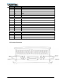
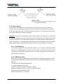
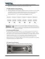
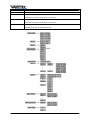
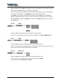
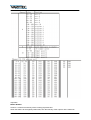
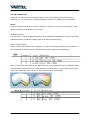
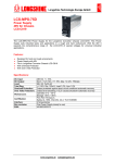
User manual
FLATBEAM DUO 48x8W
RGBW
Table of contents
1.
Safety instructions ............................................................................................................................ 4
1.1.
2.
3.
4.
5.
FOR SAFE AND EFFICIENT OPERATION ............................................................................ 4
Before usage .................................................................................................................................... 5
2.1.
Carton ...................................................................................................................................... 5
2.2.
Unpacking ................................................................................................................................ 5
2.3.
AC Power................................................................................................................................. 5
Introduction ....................................................................................................................................... 5
3.1.
Features ................................................................................................................................... 5
3.2.
DMX Channel summery .......................................................................................................... 6
3.3.
Product Overview .................................................................................................................... 7
Setup ................................................................................................................................................ 8
4.1.
Power Supply........................................................................................................................... 8
4.2.
Mounting .................................................................................................................................. 8
4.3.
Fixture linking........................................................................................................................... 9
4.3.1.
Data Cabeling .................................................................................................................. 9
4.3.2.
DMX data cable ............................................................................................................... 9
4.3.3.
Cable Connectors .......................................................................................................... 10
4.3.4.
3 Pin to 5 Pin conversion chart ...................................................................................... 10
4.3.5.
Setting up a DMX serial data link .................................................................................. 10
4.3.6.
Master Slave fixture linking ............................................................................................ 11
Operating Instructions .................................................................................................................... 11
5.1.
Control Options ...................................................................................................................... 11
5.2.
Flatbeam Control Quick setup ............................................................................................... 11
5.3.
DMX 512 control without ID addresses ................................................................................. 11
5.4.
DMX addressing with ID address .......................................................................................... 12
5.5.
Setting the DMX address ....................................................................................................... 12
5.6.
Control Panel Functions ........................................................................................................ 12
5.6.1.
Static Colour .................................................................................................................. 14
5.6.2.
Auto ............................................................................................................................... 14
5.6.3.
Run ................................................................................................................................ 14
5.6.4.
DMX ............................................................................................................................... 14
5.6.5.
Personality ..................................................................................................................... 14
5.6.6.
ID ................................................................................................................................... 15
5.6.7.
Edit custom .................................................................................................................... 15
2 / 21
5.6.8.
Setting ............................................................................................................................ 15
5.6.9.
RGbW White adjust ....................................................................................................... 16
5.6.10.
CAL1 .............................................................................................................................. 16
5.6.11.
CAL2 .............................................................................................................................. 16
5.6.12.
Key Lock ........................................................................................................................ 16
5.7.
6.
DMX 512 channel values ....................................................................................................... 17
DMX Primer .................................................................................................................................... 20
3 / 21
1. Safety instructions
•
This device is suitable for indoor use only.
•
All modifications to the device will void the warranty.
•
Repairs are to carry out by skilled personnel only.
•
Use only fuses of the same type and original parts as spare parts.
•
Protect the unit from rain and humidity to avoid fire and electric shocks.
•
Make sure to unplug the power supply before opening the housing.
1.1. FOR SAFE AND EFFICIENT OPERATION
Be careful with heat and extreme temperature
Avoid exposing it to direct rays of the sun or near a heating appliance.
Not put it in a temperature bellow 32°F /0°C, or exceeding 104°F /40°C.
Keep away from humidity, water and dust
Do not place the set in a location with high humidity or lots of dust.
Containers with water should not be placed on the set.
Keep away from sources of hum and noise
Such as transformer motor, tuner, TV set and amplifier.
To avoid placing on un-stable location
Select a level and stable location to avoid vibration.
Do not use chemicals or volatile liquids for cleaning
Use a clean dry cloth to wipe off the dust, or a wet soft cloth for stubborn dirt.
If out of work, contact sales agency immediately
Any troubles arose, remove the power plug soon, and contact with an engineer for repairing,
do not open the cabinet by yourself, it might result a danger of electric shock.
Take care with the power cable
Never pull the power cable to remove the plug from the receptacle, be sure
to hold the plug. When not using the device for an extended period of time, be sure to
disconnect the plug from the receptacle.
4 / 21
Important:
Damages caused by the disregard of this user manual are not subject to
warranty. The dealer will not accept liability for any resulting defects or
problems. Make sure the electrical connection is carried out by qualified
personnel. All electrical and mechanical connections have to be carried out
according to the European safety standards.
2. Before usage
2.1. Carton
1 x Flatbeam Duo
1 x Power Cable with Plug
1 x DMX Input Cable
1 x User Manual
2.2. Unpacking
Every Flatbeam Duo has been thoroughly tested and has been transported in perfect operating
condition. Carefully check the carton for damages that may have occurred during the transport. If
the carton appears to be damaged, carefully inspect your fixture for any damage and be sure all
accessories necessary to operate the unit has arrived intact.
2.3. AC Power
This fixture has an auto-switching power supply that can accommodate a wide range of input
voltages. The only thing necessary to do before powering on the unit is to make sure the line
voltage you are applying is within the range of accepted voltage. This fixture will accommodate
between 100V and 240V AC 50~60Hz. All fixtures must be powered directly off a switched circuit
and cannot be run off a rheostat.
3. Introduction
3.1. Features
-
3, 4, 5, 6 or 11 Channel DMX 512 Control Operating Modes.
3 Channel = RGB control
3 Channel = HSV control (hue, saturation and value)
4 Channel = RGB, Dimmer
4 Channel = RGBW Control
5 Channel = RGBW Dimmer
6 Channel = RGBW Dimmer Strobe
11 Channel = RGBW, ID, dimmer, strobe, autospeed, auto, custom programs, aso.
-
Light source 48 x 8W 4in1 High Power Leds
-
Lens: 51° Standard Lens
-
Material: aluminum body
-
Protection Rating: IP67
-
Power Consumption: 400W
5 / 21
-
Voltage: 100V – 240V 50Hz~60Hz
-
Power supply: built in and auto switching
-
Size: 508 x 196 x 533mm
-
Net weight: 23kg
3.2. DMX Channel summery
The Flatbeam has a total of 7 DMX channel configurations, referred to as “personalities” in this
manual and in the fixture onboard control board. The 7 personalities are STAG, Arc1, Ar1.D, Arc2,
Ar2.d, Ar2.s and HSV. Each of the different personalities can be accessed from the control panel.
Please see section about Control Panel Functions for a description and how to accomplish that.
STAG
Arc.1
Ar.1d
Arc.2
Channel
Description
1
Dimmer
2
Red (set the step time when pr. 01~10 is set)
3
Green (set the fade time when pr. 01~10 is set)
4
Blue
5
White
6
Color change / white balance
7
Strobe
8
Auto / custom programme
9
Speed of Auto
10
Dimmer speed
11
ID Address
Channel
Description
1
Red
2
Green
3
Blue
Channel
Description
1
Dimmer
2
Red
3
Green
4
Blue
Channel
Description
1
Red
2
Green
3
Blue
4
White
6 / 21
Ar.2d
Ar.2s
HSV
Channel
Description
1
Dimmer
2
Red
3
Green
4
Blue
5
White
Channel
Description
1
Dimmer
2
Red
3
Green
4
Blue
5
White
6
Strobe
Channel
Description
1
Hue
2
Saturation
3
Value (Brightness)
3.3. Product Overview
7 / 21
4. Setup
4.1. Power Supply
Before plugging in your unit, make sure that the voltage in your area is matching the required voltage
of your Flatbeam. This unit has an auto switching PSU which offers a wide range of input voltages.
The only thing you have to do before powering up, is to check if the line voltage you are connected to
is matching the range of accepted voltages. This fixture works between 100V and 240V 50/60 Hz. All
fixtures must be powered off a switched circuit and cannot be run on a rheostat (variable resistor) or
dimmer circuit. It is even not possible to do so if the dimmer is a switch working with 0% and 100%
only. This item is designed for power linking from one flatbeam to the other. Each fixture ships with
IP65 proprietary power input cables. Each fixture ships with a power adapter to male Edison
connector.
All fixtures must be connected to circuits with a suitable Earth Ground. Depending on the application
the lighting fixture may require a different connector. Please refer to the below wire color code for
installing a new connector:
Wire
Connection
Pin
Brown
AC Live
1
Blue
AC neutral
2
Green/Yellow
AC Ground
3
4.2. Mounting
This fixture may be mounted in any safe position.
The fixture includes a mounting yoke to which a rigging clamp can be attached. You must supply your
own clamp and make sure the clamp is capable of supporting the weight of this fixture. It is
recommended to use at least 2 mounting points per fixture.
Note: There are 2 types of applications for this fixture: floor stand for up lighting and overhead use for
down lighting. If you are using this fixture for down lighting from up above you must use at least 1
safety cable/chain for each fixture in addition to the mounting brackets.
1. If hanging the fixture for over head use, then please follow below steps.
2. Block access below the work area and use suitable and stable platform when installing or
servicing the fixture.
3. Safety cables must always be used, secured through safety cable attachment. The safety
cable must be capable of holding 10 times the weight of the fixture.
4. Verify the structure can hold 10 times the weight of all to be installed fixtures. After prolonged
periods of operation, the fixture chassis may reach high temperatures. This fixture must be
mounted in a ventilated location, as it is convection cooled.
8 / 21
4.3. Fixture linking
You will need a serial data link to run light shows of one or more fixtures using a DMX 512
controller or to run synchronized shows on two or more fixtures set to a master/slave operating
mode. The combined number of channels required by all fixtures on a serial data link determines
the number of fixtures the data link can support.
Important ! Fixtures on a serial data link must be daisy chained in one single line. To comply with
the EIA-485 standard no more than 32 devices should be connected on one data link. Connecting
more than 32 fixtures on one serial data link without use of a DMX optically isolated splitter may
result in deterioration of the digital DMX signal. Maximum recommended serial data link distance:
500m (1640ft) maximum recommended number of fixtures on a serial data link: 32 Fixtures.
4.3.1. Data Cabeling
To link fixtures together you must obtain data cables. You can purchase certified DMX Cables
directly from a dealer/distributer or construct your own cable. If you choose to create your own
cable please use data-grade cables that can carry a high quality signal and are less prone to
electromagnetic interference.
4.3.2. DMX data cable
Please use a 110 Ohms shielded cable or equivalent which meets the specifications for EIA485 applications. Standard microphone cables cannot transmit DMX data reliable over long
distances.
The cable will have following characteristics:
-
2 conductor twisted pair plus shield
-
,maximum capacitance between conductors- 30pF/ft.
-
Maximum capacitance between conductors and shield: 55pF/ft
-
Maximum resistance of 20Ohms/1000ft.
-
Nominal Impedance 100 – 140 Ohms
9 / 21
4.3.3. Cable Connectors
Cabling must have a male XLR connector onone end and a female XLR connector on the
other end
Caution! Do not allow contact between the common and the fixtures chassis ground. Grounding the
common can cause a ground loop, and your fixture may perform erratically. Test cables with an ohm
meter to verify correct polarity and to make sure the pins are not grounded or shorted to the shield or
each other.
4.3.4. 3 Pin to 5 Pin conversion chart
Note! If you use a controller with 5 Pin DMX output connector, you will need to use a 5pin to
3pin adapter. The chart below details a proper cable conversion
4.3.5. Setting up a DMX serial data
link
DMX OUT
1. Connect the (male) 3 pin connector side of
the DMX cable to the output (female) 3 pin
connector of the controller.
2. Connect the end of the cable coming from
the controller to the input connector of the
next fixture consisting of a (male) 3 pin
connector.
3. Then proceed to connect from the output
as started above to the input of the
following fixture and so on.
10 / 21
DMX OUT
DMX IN
DMX IN
4.3.6. Master Slave fixture linking
1. Connect the (male) 3pin connector side of the DMX cable to the output (female) 3pin
connector of the first fixture.
2. Connect the end of the cable coming from the first fixture which will have a (female) 3pin
connector to the input connector of the next fixture consisting of a (male) 3 pin connector.
Then proceed to connect from the output as stated above to the input of the following
fixture and so on.
DMX OUT
DMX IN
DMX OUT
DMX IN
DMX OUT
DMX IN
5. Operating Instructions
5.1. Control Options
The Flatbeam Duo is addressable in the DMX range of 001 to 512. In its simplest control from, this
allows for the control of up to 56 fixtures in the 11 channel STAG personality. However, a
secondary ID address system exists for use in a limited DMX universe and architectural
envirements. The ID address system allows the user to assign up to 66 fixtures within the same
DMX address: in effect multiplying the control of Flatbeam Duo within a single universe to 3696
fixtures. The flatbeam Duo ID address system is accessed using DMX channel 11 STAG
consideration must be placed when programming live performances or cues that need to trigger
on demand on a time line. So to remain within one second execution time, program no greater
than 10 fixtures on ID addressing per DMX channel.
5.2. Flatbeam Control Quick setup
For detailed instructions on display panel operations and functions please advance to the section
titled : display panel functions. These steps assume that you have read and are familiar ith the
setting up a serial data link.
5.3. DMX 512 control without ID addresses
The flatbeam duo operates on 11 channels of DMX (STAG personality) Address each fixture in
increments of 11 channels (i.e. 1, 12, 23, 34) to save time you can use the same DMX address for
each fixture. All fixtures will then respond simultaneously to control. You may also group your
fixtures and address those groups alike for faster programming ad control.
1. Access the control panel function by pressing the MENU button until the RUN MODE is
displayed. Press ENTER and use the UP/DOWN buttons to select DMX function. Then to
increase or decrease channels between 001 and 512.
11 / 21
2. Press the ENTER button to confirm action. Then press MENU to exit. Deactivate ID
addressing in each fixture by setting panel function ID ON/OFF to OFF.
5.4. DMX addressing with ID address
1. Follow intrsuctions ^1 for DMX 512 addressing
2. Activate ID addressing in each fixture by setting panel function ID ON/OFF to ON. SETTINGS
to ID ON/OFF to ON for every DMX 512 starting address the user can set 66 separate ID
addresses. Set ID addresses in each fixture by setting panel function ID address to
incremental values (i.e. 1, 12, 24, 36) SETTINGS to ADDRESS to 01~66
3.
5.5. Setting the DMX address
Each fixture requires a start address from 001 ~ 512. A fixture requiring one more channels for
control begins to read the data on the channel indicated by start address. For example, a fixture
that occupies or uses 5 channels of DMX and was addressed to start on DMX channel 100, would
read data from channels 100, 101, 102, 103, and 104. Choose start addresses so that the
channels used do not overlap and note the start address selected for future reference. The
Flatbeam Duo uses up to 11 channels of DMX. If this is your first time using DMX, we recommend
reading the DMX primer in the Appendix section.
5.6. Control Panel Functions
All fixtures and settings are accessible via the built-in control panel interface.
12 / 21
Button
Function
MENU
Exits from the current menu or function
UP
Navigates upwards through the menu list and
Increases the numeric value when in a function
DOWN
Navigates downwards through the menu list and
decreases the numeric value when in a function
ENTER
Enables the currently displayed menu or sets the currently
Selected value into the selected function.
13 / 21
5.6.1. Static Colour
Just go into the menu as described. Then you can adjust the
Colours red, green, blue and white from 000 to 255. That’s how you can mix the desired static colour.
The Strobe value can be set from 0 to 20 Hz.
5.6.2. Auto
-
Select the target AUTO program and press ENTER
-
Programs Aut.01 to Aut.10 are fully pre programmed and will not be altered by changes in
EDIT mode.
-
Programs Pro.01 to Pro.10 are fully pre programmed and can be edited in EDIT mode
5.6.3. Run
-
Enter the RUN mode to set the working mode.
-
DMX mode is for using DMX 512 controllers to control the fixtures.
-
Slave mode is for master-slave operation.
5.6.4. DMX
-
Enter the DMX address mode to set the DMX address from 001 to 512.
5.6.5. Personality
-
Enter the PERSONALITY mode to select DMX Mode: STAG, Arc.1, Ar1.d, Arc 2, Ar2.d,
Ar2.s or HSv
14 / 21
5.6.6. ID
Enter the ID address mode to set the ID address.
5.6.7. Edit custom
-
Enter the EDIT mode to edit the custom programs PR.01 to PR.10.
-
Each custom program has 30 steps that can be edited.
-
Each step allows the creation of a scene using RED 0~255, Green 0~255, Blue 0~255, White
0~255, Strobe 0~20, Time 0~255, & Fade 0~255. Then the data will be saved, when you
press the ENTER button for 5 seconds.
5.6.8. Setting
-
Select UPLD to upload the custom programs from the current MASTER unit to SLAVE units.
The SLAVE units must be set in mode RUN to Slave.
-
In order to activate the upload function the password must be entered
-
The password is the same as the main access password.
-
When uploading the SLAVE units will display YELLOW.
-
If an error occurs when uploading of the custom programs the SLAVE units will display RED.
-
On successful uploading of the custom programs the SLAVE units will display GREEN. In
order to reset custom modes to default values select: REST
-
Enter ID in order to allow/disallow ID address function from the DMX512 controller.
15 / 21
5.6.9. RGbW White adjust
RGB TO WHITE is set to YES, then if RGB is set to 255 255 255 the color matches a perfect
white as the actual RGB values are adjusted to make white.
When it is set to NO, then if RGB is set to 255 255 255 the RGB values are not adjusted and
the output is most powerful. The RGBW parameter can be adjusted in CAL2.
Enter DIM to select dimmer mode and dimmer speed. When DIMMER is set to OFF then
RGBW and MASTER Dimmer are linear. The Dim 1/2/3/4 are speed modes of the nin linear
dimmer, DIM1 is the faster, while DIM4 is the slowest. The DIM setting here does not react on
the STAG mode
5.6.10.
CAL1
-
Enter the CAL1 to select white color of different color temperature
-
There are 11 pre programmed white colors can be edited by using RED; GREEN; BLUE
5.6.11.
CAL2
-
Enter the CAL2 to adjust the RGB parameter to make different whites.
-
When the new setting is activated the DMX controller choose RGB = 255 255 255, the white
color will be made by the actual RGB values in the CAL2
5.6.12.
Key Lock
-
Enter the KEY mode to select wether the access password is on or off.
-
In order to enter access password it is necessary to first press ENTER.
-
Access password is UP+DOWN+UP+DOWN
16 / 21
5.7. DMX 512 channel values
17 / 21
Important!
Master Dimmer
Channel 1 controls the intensity of the currently projected color.
When the slider is at the highest position 255, then the intensity of the output is at the maximum.
18 / 21
COLOR CORRECTION
Channels 2, 3, 4 and 5 control the intensity ratio of each of the red green blue and white LEDs.
Channels 1, 2, 3, 4 and 5 can be combined together to create over 4,2 Billion color combinations.
Strobe
Channel 6 controls the strobe of channels 1 through 4. Channel 7 has priority over channels 2, 3&4
speed of the strobe is adjustable from 0 to 20Hz
ID address selection
Use channel 11 to select ID addressed fixtures. Each independent DMX address can have up to 66 ID
addresses fixtures. ID address 0 allows control of all fixtures simultaneously.
Auto & custom Program
Chanel 8 selects prest Auto/Custom Programs 1~10. When activating the Auto/Custom programs, it is
then possible to control the step time and fade time by using channels 2&3 respectively.
Note!: in HSV mode Hue stands for the visible light, such as red yellow and cyan etc. Saturation refers
to the dominance of hue in the color, when saturation is at 100% then the color is at its purest. Value
is the colors brightness, when value is at 100% then the color is at its brightest.
19 / 21
6. DMX Primer
There are 512 channels in a dmx 512 connection. Channels may be assigned in any manner. A fixture
capable of receiving DMX 512 will require one or a number of sequential channels. The user must
assign a starting address on the fixture that indicates the first channel reserved in the controller. There
are many different types of DMX controllable fixtures and they all may vary in the total number of
channels required. Choosing a start address should be planned in advance. Channels should never
overlap. If they do, this will result in erratic operation of the fixtures whose starting address is set
incorrectly. You can however, control multiple fixtures of the same type by using the same starting
address as long as the intended result is that of unison movement or operation. In other words, the
fixtures will be slaved together and all respond exactly the same.
DMX fixtures are designed to receive data through a serial daisy chain, a daisy chain connection is
where the data out of one fixture connects with the data in of the next fixture. The order in which the
fixtures are connected is not important and has no effect on how the controller communicates to each
fixture. Use an order that provides for the easiest and most direct cabling. Connect fixtures using
shielded two conductor twisted pair cable with three pin XLR male to female connectors. The shield
connection is pin 1,while pin 2 is data negative and pin 3 is data positive.
20 / 21
Importer:
B & K Braun GmbH
Industriestraße 2
D-76307 Karlsbad
www.bkbraun.com
[email protected]
21 / 21