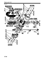
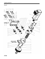
1
®
SERVOLINE Handling Components
Servo Vertical Axis
USER MANUAL
MECHANICAL PART SVA-130
BA-100022
04/2008
Change index
Editions issued so far:
Edition
02/01
03/06
04/08
Comments
First edition
Various changes
New type plate / new graphics on page 30
Order number
506614
BA-100022
BA-100022 A
II
Table of Contents
Important information ................................................................................................................................ 1
Introduction ............................................................................................................................................... 1
EU conformance (to EU Directive on Machines, Appendix II A)............................................................... 1
Product description and application.......................................................................................................... 1
Dangers..................................................................................................................................................... 1
Additional information ............................................................................................................................... 2
Validity of the User Manual ....................................................................................................................... 2
Technical data............................................................................................................................................. 3
Servo vertical axis SVA-130 ..................................................................................................................... 3
Dimensioned drawing ............................................................................................................................... 4
Load calculations for SVA......................................................................................................................... 5
Load calculations for SVA-130 with SHA.................................................................................................. 6
Load calculations for SVA-130 with FP .................................................................................................... 7
Traversing times ....................................................................................................................................... 8
Installation................................................................................................................................................... 9
Mechanical design .................................................................................................................................... 9
Designing the installation ...................................................................................................................... 9
Installation position and assembly ........................................................................................................ 9
Laying the supply lines of the additional units..................................................................................... 10
Connecting the motor cable and the resolver cable............................................................................ 11
Connecting the inductive proximity switch .......................................................................................... 12
Maintenance.............................................................................................................................................. 13
Lubrication............................................................................................................................................... 13
Setting the slide play............................................................................................................................... 14
Changing and setting the inductive proximity switch .............................................................................. 15
Changing the tool belt / Changing shafts and rollers.............................................................................. 17
Removing toothed belt (220)............................................................................................................... 18
Removing toothed belt (210)............................................................................................................... 19
Changing shafts and rollers ................................................................................................................ 20
Mounting toothed belt (210) ................................................................................................................ 22
Mounting toothed belt (220) and setting the zero point....................................................................... 24
Zero point setting................................................................................................................................. 26
Spare parts list.......................................................................................................................................... 28
Servo vertical axis SVA-130 ................................................................................................................... 29
Drive, assembled .................................................................................................................................... 31
General information ................................................................................................................................. 32
Environmental compatibility and disposal............................................................................................... 32
Materials used ..................................................................................................................................... 32
Surface treatment................................................................................................................................ 32
Shaping processes.............................................................................................................................. 32
Emissions during operation................................................................................................................. 32
Disposal............................................................................................................................................... 32
III
Important information
Introduction
This operating instruction describes the mechanical design, the load limits, the assembly, the maintenance and the spare parts of the Servo Vertical Axis SVA-130. It forms an integral part of the operating
instruction of the servo amplifier and the operator software.
EU conformance (to EU Directive on Machines, Appendix II A)
Regulations and standards taken into account:
!
EU Directive on Machines 89/392/EEC, 91/368/EEC
Manufacturer:
Montech AG
Gewerbestrasse 12
CH-4552 Derendingen
Phone
Fax
+41 (0) 32 / 681 55 00
+41 (0) 32 / 682 19 77
Product description and application
The Servo Vertical Axis SVA-130 is an electrically operated, position-controlled linear unit which serves
as a vertical unit for the construction of portal loaders. Depending on the size of the unit, movements
along the z-axis of up to 200, 400 or 600 mm are possible. Servo horizontal axes SHA, two-dimensional
servo portals FP or Linear Units (LEP) can be used for performing horizontal movements. Compact slides
(KSD), Rotary Drives DAP and Grippers GPS, GPP, etc. or any tool-bearing units can be attached as
long as the load limits of the Servo Vertical Axis SVA-130 are complied with.
Servo Vertical Axes SVA-130 which have been retrofitted to portal loaders are suitable for many and varied tasks, such as loading machines, small parts assembly, transposition, packaging, palletizing and parts
supply from magazines containing workpieces.
Dangers
The use of servo vertical axes SVA-130 in equipment is permissible only if they are protected by movable, separating protective devices according to EN 292-2 Section 4.2.2.3.
Observe the operating conditions and safety notes described in the operating instruction.
It is absolutely essential that you keep within the stated load limits.
Important!
During operation, the surface of the motor can reach 100°C. Do not touch the motor
until the temperature has dropped below 40°C (measure the surface temperature).
During maintenance work on the servo vertical axis, ensure that the power to the
drive is switched off. The servo amplifier must be disconnected from the supply voltage. Switch off the main switch or mains contactor.
•
•
•
Switch off the enable signal
Switch off the mains power (L1, L2, L3)
Ensure that no unauthorized switching-on of the supply voltage can occur.
Failure to observe these safety measures may result in death or severe injuries or
material damage.
C1
Important information
Additional information
The aim of the present User Manual is to enable users to employ the servo vertical axis SVA-130 correctly and safely. Should further information be required in relation to your particular application, please
contact the manufacturer.
When reordering User Manuals, it is essential to quote the reference number, the product name and serial number.
This document can be obtained from our homepage www.montech.com.
Fig.1
Reference number
Product name
Serial number
Montech AG
Management
U. D. Wagner
C. Wullschleger
Validity of the User Manual
Our products are continually updated to reflect the latest state of the art and practical experience. In line
with product developments, our User Manuals are continually updated.
Every User Manual has an order number (e.g. BA-100022) and an edition number (e.g. 02/2008). The
order number and the addition number are shown on the title page.
C2
Technical data
Servo vertical axis SVA-130
Max. Stroke
[mm]
Max. permissible mounting mass
[kg]
Max. speed
[mm/s]
Max. acceleration
1)
Own weight
[m/s2]
[kg]
Drive
SVA-130-200
SVA-130-400
SVA-130-600
200
400
600
5
5
5
1300
1300
1300
5
5
5
3.6
3.85
4.1
highly dynamic synchronous servo motor with locking brake
Rated motor power
[W]
130
Enclosure protection for servo motor
IP64
Transmitter system
Repeatability
Resolver
2)
[mm]
Reference position proximity switch
+/- 0.02
integrated inductive proximity switch PNP
Sound level
[dBA]
<65
Max. operating temperature of 3)
motor
[°C]
65
Ambient
conditions:
[°C]
10 - 50
Temperature
Rel. humidity
Air purity
Warranty period
Installation position
Material
5% ... 85% non-condensing
normal workshop atmosphere
2 years from date of delivery
vertical
aluminium, steel, plastic
1)
At max. permissible mounting mass
2)
At constant motor temperature.
3)
At 20°C ambient temperature
Measured at max. load, max. speed and 100 consecutive strokes
C3
Technical data
Dimensioned drawing
Fig. 3
*
SVA-130-200
SVA-130-400
SVA-130-600
C4
a
200
400
600
Adapter energy supply chain for SHA340, SHA-470, FP-340 and FP-470
b
600
700
900
Technical data
Load calculations for SVA
Fig. 4
a) Existing moments
M X = 0.001 ⋅ m ⋅ a Z ⋅ LY + 0.01 ⋅ m ⋅ LY
M Y = 0.001 ⋅ m ⋅ a Z ⋅ L X + 0.01 ⋅ m ⋅ L X
b) Load
B=
M X MY
+
≤1
27
31
S: Center of gravity of additional equipment
B:
MX, MY
m
LX, LY
aZ
Load factor: Must not exceed the value 1!
Existing moments [Nm]
Mounting mass [kg]
Distance of centre of gravity of moving mass [mm]
Acceleration of the z-axis [m/s2]
C5
Technical data
Load calculations for SVA-130 with SHA
Fig. 5
S: Center of gravity of additional equipment
a)
Existing moments
M X = 0.001 ⋅ m ⋅ (a Z ⋅ LY + aY ⋅ LZ ) + 0.01 ⋅ m ⋅ LY
M Y = 0.001 ⋅ m ⋅ a Z ⋅ L X + 0.01 ⋅ m ⋅ L X
M Z = 0.001 ⋅ m ⋅ aY ⋅ L X
b)
Existing moments
B=
M X MY M Z
+
+
≤1
27
31
26
B:
MX, MY, MZ
m
LX, LY, LZ
aY
aZ
C6
Load factor: Must not exceed the value 1!
Existing moments [Nm]
Mounting mass [kg]
Distance of centre of gravity of the moving mass [mm]
Acceleration of the y-axis [m/s2]
Acceleration of the z-axis [m/s2]
Technical data
Load calculations for SVA-130 with FP
Fig. 6
S: Center of gravity of additional equipment
a)
Existing moments
M X = 0.001 ⋅ m ⋅ (a Z ⋅ LY + aY ⋅ LZ ) + 0.01 ⋅ m ⋅ LY
M Y = 0.001 ⋅ m ⋅ (a Z ⋅ L X + a X ⋅ LZ ) + 0.01 ⋅ m ⋅ L X
M Z = 0.001 ⋅ m ⋅ (aY ⋅ L X + a X ⋅ LY )
b)
Existing moments
B=
M X MY M Z
+
+
≤1
27
31
26
B:
MX, MY, MZ
m
LX, LY, LZ
aX
aY
aZ
Load factor: Must not exceed the value 1!
Existing moments [Nm]
Mounting mass [kg]
Distance of centre of gravity of the moving mass [mm]
Acceleration of the x-axis [m/s2]
Acceleration of the y-axis [m/s2]
Acceleration of the z-axis [m/s2]
C7
Technical data
Traversing times
The traversing times were determined with an SVA-130-600 under the following conditions:
•
Load: 5 kg
•
Acceleration or deceleration: 5 m/s2
•
Start of measurement: Start signal at input X11B/2 (Fstart_No.x)
•
End of measurement: InPosition signal at output X11B/3 (InPos)
•
InPositions window: 0.05 mm
•
Low-vibration Quick-Set base
A stable, low-vibration construction is extremely important for achieving the times according to the diagram.
Fig. 7
C8
Installation
Mechanical design
Designing the installation
When designing the installation, the following points must be taken into account:
•
•
•
The servo vertical axis SVA-130 must only be operated behind a protective device according to
EN 292-2 Section 4.2.2.3.
Ensure unrestricted ventilation of the motor and keep within the permitted ambient temperatures.
Realize a low-vibration Quick-Set construction.
Installation position and assembly
Tool required
Dimension
Use for:
Hexagon socket wrench
3 mm
Item 400
4 mm
Items 11; 12
The servo vertical axis SVA-130 is installed vertically. Attachment is via the dovetail of the adapter plate
by means of two Quick-Set clamping elements SLL-55 (12).
The additional units are installed via the dovetail of the slide adapter plate with the aid of a clamping element SLL-55 (11) or SLR-15. Alternatively, the fixing holes can be used (see dimensioned drawing, Fig.
3).
The adapter of the energy conducting carrier (90) can be attached with two screws (400) and two ribbed
washers (410) on the hose holder of an SHA-340, SHA-470, FP-340 or FP-470. The straight pins for centring the adapter are mounted on the horizontal axes or two-dimensional portal in the standard version.
Fig. 8
C9
Installation
Laying the supply lines of the additional units
The supply lines can be led through the lifting arm profile.
Fig. 9
The driver connection and the fixed connection of the energy conducting carrier have pull reliefs. The
hoses and cables can be attached to the pull reliefs by means of cable ties.
Fig. 10
Pull relief
Fixed connection
Item 240
Pull relief
Driver connection
Item 230
C 10
Installation
Connecting the motor cable and the resolver cable
•
•
•
•
The servo amplifier must be disconnected from the supply voltage. Switch off the
main switch or mains contactor.
Ensure that no unauthorized switching-on of the supply voltage can occur.
During operation, the surface of the motor can reach 100°C. Do not touch the motor until the temperature has dropped below 40°C (measure the surface temperature).
Failure to observe these safety measures may result in death or severe personal
injuries or material damage.
The supplied motor cables and resolver cables are 5 m in length. Longer cables are available as options.
The cables are ready-made with coded concentric plugs on the motor side.
The motor cables and resolver cables can be laid according to Figure 11. The cables are attached to the
pull relief of the horizontal axis or of the two-dimensional portal.
Fig. 11
Motor- and resolver
cables are attached
to the pull relief (SHA
or FP)
Motor- and resolver
cables attached with
cable ties
Resolver plug
Motor plug
C 11
Installation
Connecting the inductive proximity switch
•
•
•
•
The servo amplifier must be disconnected from the supply voltage. Switch off the
main switch or mains contactor.
Ensure that no unauthorized switching-on of the supply voltage can occur.
During operation, the surface of the motor can reach 100°C. Do not touch the motor until the temperature has dropped below 40°C (measure the surface temperature).
Failure to observe these safety measures may result in death or severe personal
injuries or material damage.
The length of the cable of the proximity switch supplied is 5 m. The cable is ready-made on the proximity
switch side and is equipped with an angled plug.
The proximity switch cable can be laid according to Figure 12. The proximity switch cable can be attached with cable ties to the motor cable and resolver cable or to the pull relief of the horizontal axis or of
the two-dimensional portal.
Ensure that the proximity switch cable cannot be damaged by vertical traversing of
the axis!
Fig. 12
Proximity switch with
angled plug
C 12
Maintenance
Lubrication
•
•
•
•
The servo amplifier must be disconnected from the supply voltage. Switch off the
main switch or mains contactor.
Ensure that no unauthorized switching-on of the supply voltage can occur.
During operation, the surface of the motor can reach 100°C. Do not touch the motor until the temperature has dropped below 40°C (measure the surface temperature).
Failure to observe these safety measures may result in death or severe personal
injuries or material damage.
Fig. 13
Lubrication points
Lubrication points
Use only Klüber "Paraliq P460" Oil as lubricant.
•
•
Lubrication interval:
Lubrication points:
800 operating hours
4 lubricating nipples (Fig. 13)
C 13
Maintenance
Setting the slide play
•
•
•
•
•
•
•
•
•
•
•
The servo amplifier must be disconnected from the supply voltage. Switch off the
main switch or mains contactor.
Ensure that no unauthorized switching-on of the supply voltage can occur.
During operation, the surface of the motor can reach 100°C. Do not touch the motor until the temperature has dropped below 40°C (measure the surface temperature).
Failure to observe these safety measures may result in death or severe personal
injuries or material damage.
Remove plug (200).
Remove covers (110). Caution! Ensure that the felt wick in the cover (110) of the lubrication unit does
not fall out.
Slacken nut (10/110). Hold eccentric screw (10/100) with socket screw wrench.
Adjust the rollers to eliminate play by turning the eccentric screw (10/100) clockwise (without pretension).
Tighten nut (10/110) while holding the eccentric screw (10/100) with the socket screw wrench so that
the set slide play does not change.
Mount covers (110). Caution! The two lubricating felts in the cover must touch the shaft.
Mount plug (200; Fig. 15).
Tool required
Hexagon socket wrench
Spanner
Fig. 14
C 14
Dimension
Use for:
3 mm
Item 310
4 mm
Item 350; 10/100
14 mm
Item 10/110
Maintenance
Changing and setting the inductive proximity switch
•
•
•
•
The servo amplifier must be disconnected from the supply voltage. Switch off the
main switch or mains contactor.
Ensure that no unauthorized switching-on of the supply voltage can occur.
During operation, the surface of the motor can reach 100°C. Do not touch the motor until the temperature has dropped below 40°C (measure the surface temperature).
Failure to observe these safety measures may result in death or severe personal
injuries or material damage.
Tool required
Dimension
Use for:
Leaf gauge
0.5 mm
Distance between item 140 and item 10/160
Hexagon socket wrench
1.5 mm
Item 10/140
•
•
•
3 mm
Item 310
4 mm
Item 350
Remove plug (200).
Remove covers (110). Caution! Ensure that the felt wick in the cover (110) of the lubrication unit does
not fall out.
Slacken screw (10/140) and remove proximity switch (10/160).
Fig. 15
110
200
10/160
350
10/140
310 310
C 15
Maintenance
Fig. 16
Detail X
•
•
•
•
•
•
•
Move lifting arm to position indicated (dimension 30 mm).
Set proximity switch (10/160) according to detail X. The distance between the proximity switch
(10/160) and the damping plate (140) must be 0.5 mm.
Slightly tighten screw (10/140; Fig.15).
Mount covers (110). Caution! The two lubricating felts in the cover must touch the shaft.
Mount plug (200; Fig.15).
The LED of the proximity switch must light up when supply voltage is applied.
If this is not the case, the reference traverse can be carried out.
C 16
Maintenance
Changing the tool belt / Changing shafts and rollers
Procedure:
•
•
•
Carry out a reference traverse.
Switch off the supply voltage.
Secure the lifting arm position mechanically.
•
•
•
•
The servo amplifier must be disconnected from the supply voltage. Switch off the
main switch or mains contactor.
Ensure that no unauthorized switching-on of the supply voltage can occur.
During operation, the surface of the motor can reach 100°C. Do not touch the motor until the temperature has dropped below 40°C (measure the surface temperature).
Failure to observe these safety measures may result in death or severe personal
injuries or material damage.
Procedure after switching off the supply voltage:
•
Remove toothed belt (220)
Page C18
•
Remove toothed belt (210)
Page C19
•
Replace rollers and shafts
Page C20
•
Mount toothed belt (210)
Page C22
•
Mount toothed belt (220)
Page C24
Tool required
Hexagon socket wrench
Spanner
Adhesive tape
Dimension
Use for:
3 mm
Item 290; 300; 310; 320
4 mm
Item 350; 360; 370; 380; 390; 10/100
8 mm
Item 440
14 mm
Item 10/110; 10/120
Item 210
C 17
Maintenance
Removing toothed belt (220)
Tool required
Dimension
Use for:
Hexagon socket wrench
3 mm
Item 300; 310; 320
4 mm
Item 350; 390
Fig. 17
Procedure:
•
Remove covers (100, 110). Caution! Ensure that the four felt wicks (130) in the cover (100, 110) of
the lubrication unit do not fall out.
•
Slacken machine screws (390) and remove.
•
Slacken machine screw (300) and push servo motor to rear end position.
•
Remove toothed belt (220).
C 18
Maintenance
Removing toothed belt (210)
Tool required
Dimension
Use for:
Hexagon socket wrench
4 mm
Item 360; 370
Spanner
8 mm
Item 440
Adhesive tape
Item 210
Fig. 18
Procedure:
•
•
•
•
•
•
•
•
Slacken hexagon nut (440) and washer (430) and remove.
Slacken machine screws (360 and 370) and remove.
Open toothed belt fastening (70) and remove from the toothed belt (210).
Attach the old toothed belt (210) at the end to the new toothed belt using adhesive tape.
Carefully draw in the new toothed belt (210).
After drawing in the new toothed belt, remove the old one and dispose of.
Open toothed belt fastening at top and bottom (70) and introduce toothed belt (210).
Mount lower toothed belt fastening (70) with machine screw (370) and tighten.
C 19
Maintenance
Changing shafts and rollers
Always change the shafts (30, Fig. 20) together with the associated rollers (10/150, Fig.19 and 20).
Tool required
Hexagon socket wrench
Spanner
Dimension
Use for:
3 mm
Item 290
4 mm
Item 380; 10/100
14 mm
Item 10/110; 10/120
Fig. 19
Procedure:
•
•
•
•
•
•
Remove driver connection plate (80).
Remove end plate (60).
Slacken nut (10/110). Hold eccentric screw (10/100) with socket screw wrench.
Remove eccentric screw (10/100), shim (10/190), nut for cam (10/110) and roller (10/150).
Push new roller (10/150) onto nut (10/110).
Assemble in reverse order but without tightening the nut (10/110). It must be possible to turn the eccentric screw (10/100).
C 20
Maintenance
•
•
•
•
•
•
•
•
•
Pull shafts (30) out of the guide and insert new shafts. The shafts must be inserted into the holes in
the adapter plate (40).
Slacken nut (10/120). Hold tight-fit shoulder screw (10/170) with socket screw wrench.
Remove tight-shoulder screw (10/170), shim (10/200), nut for concentric shaft (10/120) and roller
(10/150).
Assemble in reverse order with new rollers (10/150).
Tighten nut (10/120) by holding the tight-fit shoulder screw (10/170) with the socket screw wrench.
Adjust the rollers to eliminate play by turning the eccentric screw (10/100; Fig. 19) clockwise (without
pretension).
Tighten nut (10/110; Fig. 19) while holding the eccentric screw (10/100; Fig.19) with the socket screw
wrench so that the slide play set does not change.
Mount driver connection plate (80; Fig. 19).
Mount end plate (60; Fig.19).
Fig. 20
C 21
Maintenance
Mounting toothed belt (210)
Tool required
Dimension
Use for:
Hexagon socket wrench
4 mm
Item 360
Spanner
8 mm
Item 440
Fig. 21
Procedure:
•
Mount upper toothed belt fastening (70) with machine screw (360) and generate toothed belt pretension. " Toothed belt pretension according to following chapter, page C23.
•
Mount lock nut (440) and washer (430) and tighten.
C 22
Maintenance
Toothed belt pretension of 210
The pretensions shown in the Table are maximum values and relate to a vertical axis without load. If additional units are installed, the toothed belt should be relieved by suitable
aids.
If the toothed belt is loaded with a higher pretension, this results in premature wear of
the toothed belt and an increase in the noise level.
Type
Pretension [N]
Deflection force F [N]
Deflection x [mm]
SVA-130-200
280
19.4
3
SVA-130-400
280
8.7
3
SVA-130-600
280
5.7
3
Fig. 22
C 23
Maintenance
Mounting toothed belt (220) and setting the zero point
Procedure:
•
Lifting arm position according to Fig. 23
•
Mount toothed belt (220; Fig. 24).
•
Generate toothed belt pretension by means of machine screw (300; Fig. 24).
Toothed belt pretension of 220
The pretensions shown in the Table are maximum values.
If the toothed belt is loaded with a higher pretension, this results in premature wear of
the toothed belt and an increase in the noise level.
Type
SVA-130
Fig. 23
C 24
Deflection force F [N]
Deflection x [mm]
6.7
1.2
Maintenance
Further procedure:
•
Fasten servo motor with machine screws (390) and ribbed washers (410).
•
Mount covers (100 and 110). Caution! The four lubricating felts (130) must touch the shaft.
•
Check the target positions according to the operator software manual «Commissioning after maintenance work».
Fig. 24
C 25
Maintenance
Zero point setting
•
•
Start a reference traverse (Motor travels to its zero point).
Disconnect the supply voltage from the servo amplifier. Important: observe the operating instructions
for the servo amplifier!
•
•
•
•
•
•
•
•
The servo amplifier must be disconnected from the supply voltage. Switch
off the main switch or mains contactor.
Ensure that no unauthorized switching-on of the supply voltage can occur.
During operation, the surface of the motor can reach 100°C. Do not touch
the motor until the temperature has dropped below 40°C (measure the surface temperature).
Failure to observe these safety measures may result in death or severe
personal injuries or material damage.
Remove the proximity switch cable (200, Fig. 24).
Remove the left cover (100, Fig. 24) and right cover (110, Fig. 24). Careful! Ensure that the four felt
wicks (130, Fig. 24) in the covers do not fall out!
Remove the machine screws (390, Fig. 24).
Loosen and remove the toothed belt (220, Fig. 24) by slackening the machine screw (300, Fig. 24).
It is basically possible to carry out the zero point adjustment in accordance with the section “Mounting
toothed belt (220) and setting the zero point”. Should the shaft-to-collar clamping set need to be loosened, relocated or tightened, proceed as per the following description.
•
•
•
•
•
•
•
•
•
•
•
•
Turn the tooth wheel (80, Fig. 24a) so that the bore hole in the tooth wheel lines up with the threaded
hole in the left bearing shield (20, Fig. 24a).
Screw in machine screw M5x25 as per Fig. 24b (do not tighten, only engage!)
Loosen the shaft-to-collar clamping set (240, Fig. 24b), if necessary, hold an open-ended spanner
against the gear shaft ( 70, Fig. 24b).
Slide the lifting arm to dimension 30 mm (Fig. 23) and tighten the shaft-to-collar clamping set (240,
Fig. 24b) to 25 Nm (if necessary, hold an open-ended spanner against the gear shaft ( 70, Fig. 24b)).
Remove machine screw M5x25 (Fig. 24b).
Fit the toothed belt (220, Fig. 24) (Observe the dimension of 30 mm (Fig. 23)!).
Apply toothed belt pretension via the machine screw (300, Fig. 24) (see “Toothed belt pretension of
220“ and Fig. 23).
Secure the servo motor using machine screws (390, Fig. 24) and ribbed washers (410, Fig. 24).
Fit the left cover (100, Fig. 24) and right cover (110, Fig. 24). Careful! Ensure that the four felt wicks
(130, Fig. 24) in the two covers touch the shafts!
Fit the proximity switch cable (200, Fig. 24).
Check the work that has been carried out.
Complete an offset correction in accordance with the operator software manual “Commissioning after
maintenance work”.
C 26
Maintenance
Fig. 24a
Fig. 24b
C 27
Spare parts list
Fig. 25
C 28
Spare parts list
Servo vertical axis SVA-130
Item
10
20
30
40
50
60
70
80
90
100
110
120
130
140
150
160
170
210
220
230
240
250
260
270
280
290
300
310
320
330
350
360
370
380
390
400
410
430
440
450
460
470
480
490
Designation
Article number
SVA-130-
-200
-400
-600
Basic unit
49436
49437
49438
Drive, assembled
Lifting arm profile
48827
48828
48829
Shaft
48820
48821
48822
Adapter plate
Stop, bottom
End plate
Clamping device, assembled
Driver connection plate
Fixed-point connection plate
Cover, left
Cover, right
Tube for lubrication
Wick
Damping plate
Type plate CE
Badge for type plate
Lubrication plate
Toothed belt
Toothed belt transmission
Driver connection 0180.30 MA
Fixed connection 0180.30 FA
Chain link 0180.30.50
Lubricating nipple
Pressure spring
Plug-in stop 101714
Hex. socket machine screw ISO 4762-M4x10-8.8
Hex. socket machine screw ISO 4762-M4x16-8.8
Hex. socket machine screw ISO 4762-M4x20-8.8
Hex. socket machine screw ISO 4762-M4x35-8.8
Ribbed washer BN 791-ø4.3/ø7x0.5
Hex. socket machine screw ISO 4762-M5x90-A4
Hex. socket machine screw ISO 4762-M5x45-8.8
Hex. socket machine screw ISO 4762-M5x35-8.8
Hex. socket machine screw ISO 4762-M5x16-8.8
Hex. socket machine screw DIN 6912-M5x12-8.8
Machine screw BN 1206-M5x8-10.9
Ribbed washer BN 791-ø5.3/ø8.5x0.6Bevelled washer ISO 7090-ø5.3/ø10x1
Hexagon nut ISO 4032-M5x0.8d-Kl.8
Hex. socket machine screw ISO 4762-M3x8-8.8
Hexagon nut ISO 4032-M3x0.8d-Kl.8
Washer without bevel ISO 7089-ø3.2/ø7x0.5
Circlip for shaft DIN 471-8x0.8
Socket set screws
Supplier
Material
48674
48742
48675
48681
48740
49046
48778
48779
48813
40921
55147
41620
48508
50541
506634
506632
506478
506647
506477
504554
504119
506160
Montech AG
Montech AG
Montech AG
Montech AG
Montech AG
Montech AG
Montech AG
Montech AG
Montech AG
Montech AG
Montech AG
Montech AG
Montech AG
Montech AG
Montech AG
Montech AG
Montech AG
Montech AG
Rud. Uiker AG
Rud. Uiker AG
Kabelschlepp
Kabelschlepp
Kabelschlepp
Hausamann AG
Kubo Tech AG
Maag Technik AG
Various
Various
Aluminium
Steel
Aluminium
Aluminium
Aluminium
Various
Aluminium
Aluminium
PUR
PUR
Aluminium
Wool felt
Steel
Metallized polyester
502364
Bossard AG
506668
502365
Bossard AG
Bossard AG
506864
Bossard AG
Strokeindependent
48743
PVC
Glass fibre/PUR
Glass fibre/PUR
PA
PA
PA
Brass
Steel
NR
Blackened steel
Blackened steel
Blackened steel
Blackened steel
Blackened steel
Steel
Blackened steel
Blackened steel
Blackened steel
Blackened steel
Blackened steel
Blackened steel
Blackened steel
Blackened steel
Blackened steel
Blackened steel
Blackened steel
Blackened steel
Steel
C 29
Spare parts list
Fig. 26
C 30
Spare parts list
Drive, assembled
Item
Designation
Art. No. Supplier
10
Drive, assembled
48743
10/10
Adapter plate
48787
Montech AG
Aluminium
10/20
Bearing plate, left
48777
Montech AG
Aluminium
10/30
Bearing plate, right
48776
Montech AG
Aluminium
10/40
Servo motor, assembled
48791
Montech AG
Various
10/50
Guide rod
47862
Montech AG
Steel
10/60
Deflection shaft
48796
Montech AG
Steel
10/70
Gear shaft
55153
Montech AG
Steel/Aluminium
10/80
Crown gear
55152
Montech AG
Steel/Aluminium
10/90
Stop, top
48816
Montech AG
Aluminium
10/100
Eccentric screw
48738
Montech AG
Steel
10/110
Nut for eccentric shaft
48737
Montech AG
Steel
10/120
Nut for concentric shaft
48739
Montech AG
Steel
10/130
Clamping piece
47906
Montech AG
Steel
10/140
Clamping screw
47904
Montech AG
Steel
10/150
Roller
503663 INA
Steel
10/160
Proximity switch
508449 Baumer
Various
10/170
Hex. socket tight-fit shoulder screw ISO 7379-ø8x25/M6-12.9
Steel
10/180
Hex. socket tight-fit shoulder screw ISO 7379-ø6x12/M5-12.9
Steel
10/190
Shim DIN 988-ø6/12x1
Steel
10/200
Shim DIN 988-ø8/14x1
Steel
10/210
Hex. socket machine screw ISO 4762-M5x25-8.8
Blackened steel
10/220
Ribbed washer BN 791-ø5.3/ø8.5x0.6-10.9 502365 Bossard AG
Blackened steel
10/230
Shaft-to-collar clamping set
Steel
10/240
Hex. socket machine screw ISO 4762-M6x16-8.8
Steel
10/250
Washer ISO 7093-ø6.4/ø18x1.6
Steel
10/260
Straight pin, hardened and ground, ISO 8734 ø5h6x28
Steel
10/270
Plug-in stop
NR
10/280
Spring washer DIN 127B-ø6.1/ø11.8/1.6
10/290
Cushioning disc
508054 SFS Unimarket
506160 Maag Technik AG
Material
Blackened steel
55151
Montech AG
Steel
C 31
General information
Environmental compatibility and disposal
Materials used
•
•
•
•
•
•
•
Aluminium
Steel
Brass
Wool fibres
PUR
Polyurethane
PA
Polyamide
NR
Natural rubber
Surface treatment
•
•
Anodic oxidation of aluminium
Blackening of steel
Shaping processes
•
•
•
Profile extrusion of aluminium
Machining of metals and plastics
Vacuum-casting of plastics
Emissions during operation
•
None
Disposal
Servo vertical axes (SVA-130) or handling units retrofitted to portal loaders that are no longer in use are
to be dismantled into individual parts and recycled according to the type of material. The type of material
for each part is stated in the spare parts lists. Any non-recyclable material is to be disposed of properly
according to materials, taking into account the regulations which apply in your location.
C 32