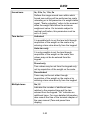
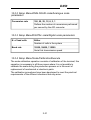
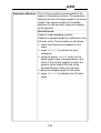
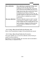
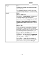
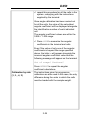
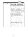
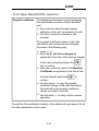
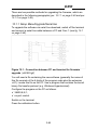
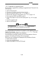
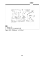
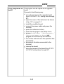
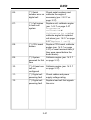
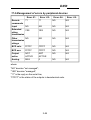
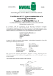
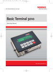
1
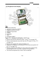
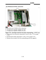
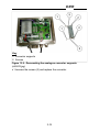
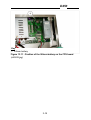
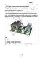
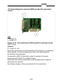
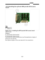
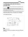
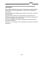
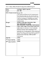
SOCIETÀ COOPERATIVA
BILANCIAI
D450 Terminal
Use, maintenance and installation manual
Code 813926
EDITION 2 September 2002
D450
Index
12. SAFETY INSTRUCTIONS FOR THE INSTALLER
3-5
13. OPENING THE TERMINAL
13.1 Opening the stainless steel casing
13.2 Main parts of the terminal
13.3 Keyboard and display
13.4 Access to the converter and scale connectors
13.5 CPU board extraction
13.6 Removal of the power supplier
13.7 Removal of the converter
13.8 Removal of the CPU
13.9 Replacing the lithium battery
13.10 Installing the optional MPP board
13.11 How to insert other optional boards
13.12 Installing the optional 4 I/O board
13.13 Installing the optional serial ports board
13.14 Installing the optional BCD parallel 5V-calculator board
13.15 Installing the optional BCD parallel 24V-source board
3-7
3-7
3-8
3-9
3-10
3-11
3-12
3-14
3-17
3-17
3-19
3-20
3-21
3-21
3-22
3-23
14. PERSONALIZING METROLOGICAL PARAMETERS
14.1 Calibration button
14.2 Description of the main menus and metrological parameters
14.2.1 Setup Menu/Scale/Configurations/Metrological
14.2.2 Setup Menu/ANALOGUE scale/Analogue scale parameters
14.2.3 Setup Menu/DIGITAL scale/Digital scale parameters
14.2.4 Setup Menu/Scale/Calibration/Execute
14.2.5 Setup Menu/Scale/Calibration/Display data
14.2.6 Setup Menu/Scale/Calibration/Correction
14.2.7 Setup Menu/DIGITAL scale/Calibration/Angle calibr.
14.2.8 Setup Menu/DIGITAL scale/Test
14.2.9 Setup Menu/DIGITAL scale/Terminal data storage
14.2.10 Setup Menu/DIGITAL scale/Terminal data reinstatement
14.3 Repeater scale
14.3.1 Setup Menu/Scale/Repeater scale parameters/Serial port/String
3-25
3-25
3-27
3-28
3-31
3-31
3-31
3-35
3-35
3-37
3-41
3-42
3-42
3-43
3-43
15. SOFTWARE UPGRADE
15.1 Setup Menu/Upgrade
15.1.1 Setup Menu/Upgrade/Serial line
15.1.2 Upgrade via upgrade board
3-45
3-45
3-46
3-48
16. MAINTENANCE
16.1 Setup Menu/Maintenance
3-51
3-51
17. TROUBLESHOOTING
17.1 CPU and converter faults
17.2 Management of errors by peripheral devices
3-55
3-56
3-59
3-3
D450
3-4
D450
12. SAFETY INSTRUCTIONS FOR THE
INSTALLER
CAUTION
The information and instructions contained in this section are
addressed exclusively to installation personnel who must
have specialised knowledge in the fields of electrical and
electronic engineering and programming.
A number of the operations described herein require the
removal of legal seals and the opening of the terminal
casing.
Furthermore, certain operations can be only performed when
the terminal is connected to the electrical power supply.
In this condition, some of the exposed electrical components
will be live and consequently there is a risk of electric shock.
Any dismantling or opening of the terminal by the user or any
other unauthorised person shall immediately invalidate the
warranty and release the Manufacturer from all liability for
any personal injury or damage sustained.
Also consult the "Safety instructions" " chapter of the user
manual.
3-5
D450
3-6
D450
13. OPENING THE TERMINAL
13.1 Opening the stainless steel casing
Key
1. casing screws
Figure 13.1 - Opening the terminal (citi0615.jpg)
✔ Unplug the mains lead connector;
✔ Remove the 4 screws indicated in fig. 13.1 on page 3-7.
3-7
D450
13.2 Main parts of the terminal
Key
1. Power supplier
2. Slots for optional boards
3. Scale input converter (protected by a seal)
4. MPP (hidden by the converter in the figure)
5. Display
6. Scale input (protected by a seal)
Figure 13.2 - Main parts of the terminal (citi0616.jpg)
3-8
D450
13.3 Keyboard and display
Key
1. Ground connection
2. Keyboard connection (JTAST)
3. Display connection (JLCD)
4. Display fixing screws
5. Display
6. Keyboard
7. Nuts
8. Keyboard support
Figure 13.3 - Keyboard and display (citi0617.jpg)
✔ Remove the ground connection (point 1 of fig. 13.3 on page 3-9).
✔ Remove the keyboard connection from the CPU (point 2 of fig. 13.3
on page 3-9).
✔ Remove the separate the keyboard-display unit.
✔ Separate the display by unscrewing the four screws (see points 4 of
fig. 13.3 on page 3-9).
✔ Besides separating the display (5), also remove the support (8) by
unscrewing the nuts (7) in order to replace the keyboard (6).
✔ This frees the keyboard (6) so that it can be replaced.
3-9
D450
13.4 Access to the converter and scale connectors
Key
1. Screws allowing access to the converter
2. Screws allowing access to the connectors
Figure 13.4 - Screws allowing access to the converter and scale
connectors (citi0618.jpg)
✔ Unscrew the cover fixing screws after having removed the seal (see
points 1 and 2 of fig. 13.4 on page 3-10).
✔ Remove the protective covers.
3-10
D450
13.5 CPU board extraction
Key
1. Fixing screws
2. Fixing screws (not visible in the figure)
Figure 13.5 - CPU board screws (citi0619.jpg)
The CPU board (complete with power supplier, converter and optional
boards) must be removed from the casing in order to carry out the
following operations.
✔ Disconnect the CPU board connectors.
✔ Unscrew the screws shown in points 1 of fig. 13.5 on page 3-11 and
screw 2 which is not visible in the figure.
✔ Take out the board.
3-11
D450
13.6 Removal of the power supplier
Key
1. Screws
2. Powering connector JAL
Figure 13.6 - Removal of the power supplier. Metal support side
(citi0620.jpg)
3-12
D450
Key
1. Rod
Figure 13.7 - Removal of the power supplier. Lower side of CPU
board (citi0621.jpg)
✔ Disconnect connector JAL (see point 2 of fig. 13.6 on page 3-12).
✔ Unscrew the 3 screws shown in points 1 of fig. 13.6 on page 3-12.
✔ Unscrew the rod on the bottom shown by point 1 of fig. 13.7 on page
3-13.
3-13
D450
13.7 Removal of the converter
Key
1. Screws (one is hidden by the connector)
2. Connector for signals towards the CPU
3. Connector for signals towards the cells
Figure 13.8 - Analogue terminal converter demounting (citi0622.jpg)
✔ Disconnect the connectors (see points 2 and 3 of fig. 13.8 on page
3-14).
✔ Unscrew the screws (see points 1 of fig. 13.8 on page 3-14).
✔ Remove the converter from the casing along with the supports.
3-14
D450
Key
1. Converter supports
2. Screws
Figure 13.9 - Demounting the analogue converter supports
(citi0623.jpg)
✔ Unscrew the screws (2) and replace the converter.
3-15
D450
Key
1. Screws
Figure 13.10 - Demounting the digital converter supports
(citi0624.jpg)
After having removed the converter unit from the CPU, unscrew the
screws from the supports (see points 1 of fig. 13.10 on page 3-16) and
replace the board.
3-16
D450
13.8 Removal of the CPU
To remove the CPU board, proceed as follows:
✔
✔
✔
✔
remove the board as described in par. 13.5 on page 3-11;
demount the power supplier as described in par. 13.6 on page 3-12;
demount the converter as described in par. 13.7 on page 3-14;
demount the optional boards and the support that holds them in place
as explained in par. 13.11 on page 3-20.
13.9 Replacing the lithium battery
To replace the lithium battery proceed as follows:
✔ switch off the terminal and disconnect the mains lead;
✔ open the terminal as indicated in par. 13.1 on page 3-7;
✔ reconnect the mains lead and switch the terminal on (the battery must
be replaced when the terminal is powered on to prevent loss of data);
✔ remove the battery from the battery holder (point 1 fig. 13.11 on page
3-18);
DANGER
Take care not to cause short-circuits between the metal
components.
✔ fit a charged battery. Only use a lithium CR 2450 battery;
✔ dispose of the old battery in accordance with applicable regulations.
Do not dispose of it improperly.
3-17
D450
Key
1. Lithium battery
Figure 13.11 - Position of the lithium battery on the CPU board
(citi0625.jpg)
3-18
D450
13.10 Installing the optional MPP board
✔ Demount the converter as described in par. 13.7 on page 3-14.
✔ Find connectors MPP1 and MPP2 under it.
✔ Make sure that jumper P3 on board CPU is connected.
✔ Centre board MPP on the connectors.
Consult fig. 13.12 on page 3-19 where the connectors on the CPU board
are more clearly shown.
Key
1. Jumper P3
2. Connectors for the MPP board
Figure 13.12 - CPU board (citi0626.gif)
3-19
D450
13.11 How to insert other optional boards
Optional boards may be inserted in any of the slots provided. On
switching the terminal back on the software will automatically detect and
identify the type of board (plug & play).
Refer to the Options chapter of the user manual for the output codes.
Optional boards may be inserted straight into the slots as soon as the
terminal is opened (see par. 13.1 on page 3-7 and par. 13.2 on page
3-8). If this operation is difficult to carry out, take out the CPU board (as
explained in par. 13.5 on page 3-11) and insert the boards from outside
the casing (see fig. 13.13 on page 3-20).
Key
1. Slot 1
2. Slot 2
3. Hole for the slot 1 fixing screw
4. Hole for the slot 2 fixing screw
Figure 13.13 - Installing the optional board (citi0627.jpg)
3-20
D450
13.12 Installing the optional 4 I/O board
Insert the board as shown in fig. 13.13 on page 3-20.
Personalize the parameters that refer to the I/O (see Personalization
chapter of the advanced user manual).
Refer to the Options chapter of the user manual for the connections.
13.13 Installing the optional serial ports board
Insert the board as shown in Figure 13.13 on page 3-20.
Personalize the serial port parameters (consult Personalization chapter
of advanced user manual).
See Options chapter of the user manual for the connections.
3-21
D450
13.14 Installing the optional BCD parallel 5V-calculator
board
Key
1. jumper P1
2. jumper P2
Figure 13.14 - Personalizing the BCD parallel 5V-calculator board
(log0121.jpg)
Jumpers
P1 on pin 25 i +5V.
Should be connected to the first terminal in IDC systems. It is generally
disconnected. For special applications refer to the specifications.
P2 identifies the board type.
Connected for BCD 5V-calculator output in number of divisions.
Disconnected for BCD 5V multiplied output.
Personalize the relative parameters (see Personalization chapter of
advanced user manual).
See Options chapter of the user manual for the connections.
3-22
D450
13.15 Installing the optional BCD parallel 24V-source
board
Key
1. jumper P1
2. jumper P2
Figure 13.15 - Installing the BCD parallel 24V-source board
(log0121.jpg)
Jumpers
P1 permanently disconnected
P2 permanently disconnected
Personalize the relative parameters (see Personalization chapter of
advanced user manual).
See Options chapter of the user manual for the connections.
3-23
D450
3-24
D450
14. PERSONALIZING METROLOGICAL
PARAMETERS
The terminal setup procedure can be accessed in two different ways.
✔ By pressing
on power up (as explained in the Personalization
chapter of the advanced user manual) it is possible to access
non-metrological parameters. In this way, the metrological parameters
can be displayed but not modified.
✔ With the terminal switched on, after removing the seals, by pressing
the calibration button (see par. 14.1 on page 3-25) it is possible to
modify all the parameters, both metrological and non-metrological.
14.1 Calibration button
Key
1. Calibration button
Figure 14.1 - Position of the calibration button on the CPU board
(citi0628.gif)
3-25
D450
If you access the setup procedure by pressing the calibration button it is
possible to modify all the terminal parameters.
The correct procedure is as follows:
✔ remove the seals from the instrument (lead seals or label) and the
converter casing (point 3 fig. 13.2 on page 3-8);
✔ switch on the terminal;
✔ press the calibration button using a non-metallic pointed instrument
(point 1 fig. 14.1 on page 3-25;
✔ select the menu display language; a few terminal identification
messages will be displayed briefly (program code, version, serial
number) immediately followed by the Setup menu.
On exiting Setup, the display language selected in the personalization
menu will be restored.
WARNING
Access to setup parameters by way of the calibration button
is restricted to specialised personnel only.
Any tampering by unauthorised personnel shall invalidate the
warranty with immediate effect.
The main metrological parameters are described in the following
paragraphs. For personalization of non-metrological parameters refer to
the Personalization chapter of the advanced user manual.
3-26
D450
14.2 Description of the main menus and metrological
parameters
Unless different indications are given, the description of the parameters
illustrated in the following paragraphs is valid for both analogue and
digital scales.
The configuration and calibration menus double in the case of a double
analogue scale.
The parameters of both scale A (input JCELA) and scale B (input
JCELB) must therefore be customised (see "Connections to the internal
terminals" paragraph in the user manual).
There is no distinction in the case of a digital scale and slave as only
one scale is controlled.
Consult par. 14.3 on page 3-43 for a description of the slave menus and
parameters.
3-27
D450
14.2.1 Setup Menu/Scale/Configurations/Metrological
Scale
analogue, digital, repeater
Legal
NO, YES
Unit of measurement kg, g, t, lb
If you select a different unit of measurement
from that previously set, the terminal will not
convert the unit of measurement. In this case
it will be necessary to recalibrate the scale
using sample weights of the selected unit of
measurement.
Ranges
SINGLE, TWO MULTIDIVISION, TWO
MULTIEXTENSION, THREE
MULTIDIVISION, THREE MULTIEXTENSION
Division
0.001, 0.002, 0.005, 0.010, 0.020, 0.050, 0.01,
0.02, 0.05, 0.1, 0.2, 0.5, 1, 2, 5, 10, 20, 50
Minimum division value expressed in the
selected unit of measurement. When selecting
this value, bear in mind the number of decimal
places to be displayed. Shows the division of
the last field in the case of MD and ME
instruments.
capacity
editor
1st range capacity
editor
2nd range capacity
editor
3-28
D450
No. of divisions for
stability signal
0, 1, 2, 4
high resolution
YES, NO
Defines the number of divisions by which the
weight may vary while the weight stable signal
is maintained. On terminals subject to metrical
verification, this parameter must be set to 0
(zero) or 1.
High resolution operating parameter. This
function is useful for weighing tests and scale
calibration, as it allows the weight reading to
be displayed in tenths of a division. It is not
enabled during normal terminal operation. It is
used primarily during scale testing.
zero track
0e, 0.25e, 0.5e, 1e
Defines the range around zero within which
zero tracking is performed to small gradual
variations in the weight reading, caused, for
example, by dust settling on the scale.
✔ For dosing systems, set the parameter to 0
(zero)
✔ When zero tracking is disabled by selecting
0 (zero), the forced zero function is also
automatically disabled. This applies even if
the forced zero parameter is set to a value
other than 0 (zero).
3-29
D450
forced zero
0e, 0.5e, 1e, 1.5e, 2e
Defines the range around zero within which
forced zero setting will be performed on scale
unloading or in the presence of a weight stable
signal. "Scale unloading" refers to the moment
when the weight falls below the minimum
weighment value. On terminals subject to
metrical verification, this parameter must be
set to 0 (zero).
Tare device
Activated
It is possible both to set the tare both through
acquisition of the weight on the scale or by
entering a tare value directly from the keypad.
Auto-tare only
It is only possible to set the tare through
acquisition of the weight on the scale; tare
values may not be be entered from the
keypad.
Preset only
Tare values may be set from the keypad only,
not by acquisition of the weight on the scale.
De-activated
Tares may not be set either through
acquisition of the weight on the scale or by
entering a tare value directly from the keypad.
Multiple tares
No,1,2
Indicates the number of additional tares
relative to the acquired tare and the tare
entered from the keypad. "No" indicates no
additional tares. For more detailed information
also consult the Use of the terminal chapter of
the user manual (Tare and preset tare
display).
3-30
D450
14.2.2 Setup Menu/ANALOGUE scale/Analogue scale
parameters
Conversion rate
100, 50, 25, 12, 6, 3, 1
Defines the number of conversions performed
per second by the A/D converter.
14.2.3 Setup Menu/DIGITAL scale/Digital scale parameters
N. of load cells
Editor
Number of cells in the system
Baud rate
19200, 38400, 115200
Serial link transmission speed
14.2.4 Setup Menu/Scale/Calibration/Execute
The scale calibration operation consists of calibration of the terminal; this
operation is necessary in all those cases where it is not possible to
calibrate the scale during the production process or in the event of
replacement of mechanical or electronic parts.
The calibration procedures have been developed to meet the practical
requirements of the different situations that may arise.
3-31
D450
Standard calibration This is the procedure recommended for the
majority of weighing systems. This procedure
requires the use of sample weights or a known
weight. Use sample weights of a suitable
precision for the accuracy class and capacity
of the terminal.
Zero full scale
Used for linear weighing systems.
Requires a sample weight for calibration of the
full scale value. The procedure is as follows:
✔ check that there are no weights on the
scale;
✔ press EXECUTE to perform the zero
calibration;
✔ using the option CHANGE, enter the full
scale weight value (corresponding to the
value of the sample weight) (to enter the
numeric value consult the Use of the
terminal chapter of the user manual);
✔ place the sample weight on the scale;
✔ press EXECUTE to calibrate the full scale
value.
3-32
D450
Linearized at one point, Linearized at two
points
In systems which are non-linear, in addition to
zero and full scale calibration, you can also
calibrate intermediate points which are valid
for both the rising and falling sides of the
actual weight/measured weight curve.
For linearized calibration at least 2 sample
weights are required: the first for calibration of
the intermediate point, and a second for
calibration of the full scale value.
For 2-point linearized calibration, at least 3
sample weights are required: the first for
calibration of the first intermediate point, a
second for calibration of the second
intermediate point, and a third for calibration of
the full scale value.
The procedure (indicated by on-screen
instructions) is the same as that used for Zero
Full scale calibration, except that in this case
more points are to be calibrated.
3-33
D450
Hysterisis correction at one point,
Hysterisis correction at two points
In systems which present a hysterisis, in
addition to zero and full scale calibration, you
can also calibrate different intermediate points
for the rising and falling sides of the actual
weight/measured weight curve.
At least 2 sample weights are required for 1
point hysteresis correction, one to calibrate the
1st intermediate point, the other to add to the
first to calibrate the full scale value.
The down-scale is calibrated by removing the
weights in reverse order.
At least 3 sample weights are required for two
point hysteresis correction, one to calibrate the
1st intermediate point, the second to add to
the 1st to calibrate the 2nd intermediate point
and the third to add to the first two to calibrate
the full scale value.
The down-scale is calibrated by removing the
weights in reverse order.
The procedure (indicated by on-screen
instructions) is the same as that used for Zero
Full scale calibration, except that in this case
more points are to be calibrated.
3-34
D450
Zero calibration
Zero calibration is necessary in those cases
where the scale has been previously
calibrated, but on switching the terminal the
zero is found to have shifted; this may occur
when the pre-tare value used for the original
calibration is not known, or when an
exceptional load is present on the scale. No
sample weights are required for this operation.
The procedure is indicated by on-screen
instructions.
Reverse calibration
Reverse calibration may be useful in certain
cases where it is difficult to load or unload a
known weight from the weighing device, such
as for example in hopper or dosing systems.
The procedure is indicated by on-screen
instructions.
14.2.5 Setup Menu/Scale/Calibration/Display data
Refer to the Personalization chapter of the advanced user manual.
14.2.6 Setup Menu/Scale/Calibration/Correction
This option enables you to correct the calibration without having to
repeat the entire procedure.
Depending on the data available, the correction can be calculated in
different ways, as explained below.
3-35
D450
Weight
Editor
If the weight is known, the correction can be
entered directly.
The value entered must lie within the range:
- (Capacity/100) < Weight < + (Capacity/100)
Gravity
Editor
place of calibration
On selecting Campogalliano (headquarters
of the Manufacturer) the gravitational
acceleration value of Campogalliano (9.80552
m/s) is entered automatically), otherwise it is
possible to enter a gravitational acceleration
value within the range (9.60000 to 10.00000)
m/s.
place of use
As the gravitational acceleration of the place
of calibration is known, in order to calculate
the weight correction value it is also necessary
to know the gravitational acceleration of the
place of use. You can enter a value within the
range (9.60000 to 10.00000) m/s.
Alternatively, you can enter the Coordinates
of the place of use: latitude (0 to 90)° and
altitude (-1000 to +9000) m.
On the basis of these data, the program will
calculate the weight correction and enter the
value obtained in the parameter Weight .
3-36
D450
14.2.7 Setup Menu/DIGITAL scale/Calibration/Angle calibr.
Angle calibration is used to correct digital cell assembly errors,
constructional tolerances, etc.
To carry out the angle calibration operation, the sample weight (not
necessarily known) must be loaded in sequence into each digital cell.
3-37
D450
Progressive
calibration (1, 2, , n)
The weight and weighing symbols initially
appear on the display. Remember that angle
calibration usually occurs before sampling,
thus the weight value that appears on the
display is not real but only indicative of the fact
that there is something on the scale.
Proceed in the following way:
✔ unload the scale and press READY; after 30
seconds (the time required for the scale to
stabilize) the positions of the digital cells in
the system will appear on the display. Each
digital cell is represented by a rectangle
and an identification number. The empty
rectangles indicate cell stability.
If they are not addressed, the cells will be
arranged in sequence without identification
number. This display remains for the time
required to acquire the minimum dead load
of all the cells and then returns to the
normal weight display.
✔ Load the sample weight on cell 1 when the
Load the cell 1 indication appears on
the display;
✔ press READY to acquire the sample weight
value. After this, the cell positions in the
system are displayed again.
This display remains for the time required
to acquire the weight on all cells when cell
1 is loaded with the sample weight;
3-38
D450
✔ repeat this procedure for all the cells in the
system, complying with the instructions
supplied by the terminal.
Once angle calibration has been carried out
for all the cells, the value of the calculated
angular coefficient will be displayed alongside
the identification number of each individual
cell.
The angular coefficient values are within the
0.995 ÷ 1.005 range.
✔ Press SAVE to memorize the angular
coefficients in the terminal and cells.
Even if the value of only one of the angular
coefficients is beyond the range specified
above, the letter e will appear alongside the
incorrect angular coefficient value and the
following message will appear on the terminal
Out of range! Continue?
Press REPEAT to repeat the angular
coefficient calculations.
Calibration by side
(1, 3, , 4, 2)
The instructions given for progressive
calibration are also used in this case, the only
difference being the order in which the cells
must be loaded with the sample weight.
3-39
D450
Replace 1 cell
It may be necessary to replace a cell in the
system. In this case, the angular coefficient
can be calculated for the replaced cell without
having to calibrate all the other cells.
Proceed in the following way:
✔ unload the scale and press READY.
The cells appear on the display arranged in
sequence and without identification
numbers. This display remains for the time
required to acquire the minimum dead load.
✔ Load the sample weight on the replaced
cell when requested by the terminal and
press READY to acquire its value;
✔ load the sample weight on the cell
diametrically opposite the replaced one
when requested by the terminal and press
READY.
The terminal will calculate the angular
coefficient for the replaced cell.
✔ Press SAVE to record the angular
coefficient in the terminal and cell.
There terminal will indicate if the angular
coefficient value is beyond the tolerated limits.
In this case, press REPEAT to repeat the
calculations.
✔ Switch off the terminal.
3-40
D450
14.2.8 Setup Menu/DIGITAL scale/Test
Angular coefficient
The following information is given alongside
the identification number of each individual
cell:
✔ the correction made through angular
calibration of the cell, recorded in the cell;
✔ the same correction recorded in the
terminal.
The angular coefficient values of the cells
recorded in the terminal can be changed.
Proceed in the following way:
✔ press EDIT;
✔ enter the N° cell to be changed as
explained in the Use of the terminal chapter
of the user manual and press the
key to confirm;
✔ enter the numerical value of the Modified
Coefficient as explained in the Use of the
terminal chapter and press
to
confirm;
✔ use the arrow ←to copy the angular
coefficient values of the cells recorded in
the terminal on the angular coefficient
values recorded in the cells;
✔ use the arrow → to carry out the reverse
operation.
Consult the Personalization chapter of the advanced user manual for all
the other parameters in this menu.
3-41
D450
14.2.9 Setup Menu/DIGITAL scale/Terminal data storage
Important information for the operation of the terminal are recorded on
the terminal board. This information includes the sampling data, the
angular coefficients, the serial numbers and the cell addresses, etc.
These data can also be saved in the cells by means of the Terminal
data storage item.
14.2.10 Setup Menu/DIGITAL scale/Terminal data
reinstatement
The cell data (sampling, serial numbers, angular coefficients, addresses)
can be loaded into the terminal.
3-42
D450
14.3 Repeater scale
14.3.1 Setup Menu/Scale/Repeater scale parameters/Serial
port/String
All the parameters listed below must be selected in the same way as
they were for the main terminal. Consult par. 14.2.1 on page 3-28.
CB
Enter the following parameters:
✔ unit of measurement: kg,g,t,lb;
✔ division: 0.001, 0.002, 0.005, 0.010,
0.020, 0.050, 0.01, 0.02, 0.05, 0.1, 0.2, 0.5,
1, 2, 5, 10, 20, 50.
Visual
Enter the following parameters:
✔ unit of measurement: kg,g,t,lb;
✔ division: 0.001, 0.002, 0.005, 0.010,
0.020, 0.050, 0.01, 0.02, 0.05, 0.1, 0.2, 0.5,
1, 2, 5, 10, 20, 50.
Extended
Enter the following parameters:
✔ ranges: SINGLE, TWO MULTIDIVISION,
TWO MULTIEXTENSION, THREE
MULTIDIVISION, THREE
MULTIEXTENSION;
✔ division: 0.001, 0.002, 0.005, 0.010,
0.020, 0.050, 0.01, 0.02, 0.05, 0.1, 0.2, 0.5,
1, 2, 5, 10, 20, 50;
✔ capacity: enter the numerical value as
explained in the Use of the terminal chapter
of the user manual;
✔ 1st range capacity: as above;
✔ 2nd range capacity: as above.
3-43
D450
Consult the Personalization chapter of the advanced user manual for the
other parameters in this menu.
Refer to chapters 15 and 16 of this section for maintenance and
software updates.
3-44
D450
15. SOFTWARE UPGRADE
15.1 Setup Menu/Upgrade
You can:
✔ update the program version;
✔ update the program.
In the first case, all the parameters including sampling and the archives,
remain unchanged.
In the second case, the parameters, metrological data, any prints,
transmissions and personalized messages do not change. However,
remember that if the new program involves substantial changes to the
operating mode or further parameters, the old configuration could be
wrongly interpreted. This is why it is advisable to print the report before
and after the update in order to make sure that the parameters are
correct.
The data in archives common to both programs remain unchanged.
The logo of the terminal can be loaded and cancelled via Dialogic. It is
not changed by initialization or by an update.
CAUTION
If the CPU board is replaced it may also be necessary to
update the software on the new board so that it matches that
of the old board.
Make sure that the installed software and board are
compatible with each other.
Do not interrupt the updating procedure as this could impair
the result of the downloading operation.
More detailed information is available on request from the
Manufacturer.
3-45
D450
There are two possible methods for upgrading the firmware, which are
described in the following paragraphs (par. 15.1.1 on page 3-46 and par.
15.1.2 on page 3-48).
15.1.1 Setup Menu/Upgrade/Serial line
To upgrade the software via serial line download, switch off the terminal
and connect a serial line cable between a PC and Com 1 (see fig. 15.1
on page 3-46).
Figure 15.1 - Connection between PC and terminal for firmware
upgrade (citi0629.gif)
You will need a file containing the new software (generally the name of
this file consists of the 6 digits of the program code plus the extension
.a37). Locate this file on the PC. Use a program that contains the kermit
binary file transfer protocol (e.g. Windows Hyperterminal).
Configure the program on the PC as follows:
✔ 38400,8,N,1;
✔ no port control.
Switch on the terminal.
Press the calibration button.
3-46
D450
Follow the menu path:
Italian>Upgrade>Serial line>Software upgrade via
serial line... CAUTION: the program will be deleted;
have upgrade ready.
CONTINUE?> YES
Premendo il tasto
selezionare kermit protocol.
The terminal launches a new program (boot program) that allows you to
install the new firmware.
The terminal will give the following instructions:
Connect com01 to host, select kermit protocol, 38400,
8, N, 1 (Connect host with Kermit protocol to com1, configuration
38400, 8, N, 1)
The terminal will set on hold and give the .waiting message,
cancelling the program it contains..
Transmit the file with the new software version from the PC by means of
the Kermit procedure.
On receiving the file, the terminal displays the message .loading.
On completion of the transfer procedure the terminal displays
.correctly terminated: switch off. (transfer completed
successfully; switch off the terminal).
Should any error messages be displayed notify Assistance Service.
Switch the terminal off and then on again before using the new software.
3-47
D450
15.1.2 Upgrade via upgrade board
The firmware is upgraded by installing an upgrade board. Proceed in the
following way:
✔
✔
✔
✔
✔
✔
switch off the terminal;
disconnect all cables connected to the terminal;
open the casing as shown in par. 13.1 on page 3-7;
demount the converter as described in par. 13.7 on page 3-14;
find connectors MPP1 and MPP2 under it;
remove the jumper P3 on the CPU board (point 1 fig. 15.2 on page
3-49);
✔ insert the upgrade card;
✔ switch on the terminal.
CAUTION
This operation exposes some parts of the internal circuitry.
Be careful not to cause accidental short-circuits!
The terminal detects the presence of program on the upgrade board and
displays the message .Upgrade software from board. The code
of the program to be installed is also displayed.
The subsequent messages indicate the successful deletion of the old
program, the loading and testing of the new program.
Should any error messages be displayed notify Assistance Service.
✔ Switch off the terminal;
✔ remove the upgrade board;
✔ replace the jumper P3 on the CPU board.
3-48
D450
Key
1. Jumper P3
2. Connectors for upgrade board
Figure 15.2 - CPU board (citi0626.gif)
3-49
D450
3-50
D450
16. MAINTENANCE
16.1 Setup Menu/Maintenance
WARNING
Accessing these menu options could delete all the data in
the terminal memory!
3-51
D450
Serial number
For entering the terminal serial number: check
seal labels.
Parameter report
Reserved
Initialization
Parameters initialization
Restores the initial terminal configuration
parameters (including calibration).
Initialization complete
Restores the initial terminal status as regards
parameters, files and all general data.
Cancel MPP board
Returns the MPP memory board to its initial
state.
Inizialize MPP codes Returns print to initial status.
Test report
Displays results of the tests performed on the
terminal during the production process.
3-52
D450
Copy programme on The program can be copied on an upgrade
board.
board
Proceed in the following way:
✔ move the jumpers of the upgrade board
from P3-P4 to P1-P2, turning them through
90°;
✔ open the cover of the instrument as shown
in fig. 13.1 on page 3-7;
✔ install the modified board;
✔ connect the power cable and power the
terminal;
✔ press the calibration button;
✔ select the language in the Setup menu;
✔ access Setup Menu / Maintenance /
Copy programme on board and
program as instructed by the terminal;
✔ turn off the terminal once the operation has
terminated;
✔ disconnect all cables connected to the
terminal;
✔ remove the board;
✔ move the jumper of the board from P1-P2
to P3-P4, turning them through 90°.
3-53
D450
Cell emergency
routine
Connect one digital cell at a time to activate
this.
The following data are displayed for each
individual cell: baud rate, address, program
code, serial number and angular
coefficient.
Press the following keys:
✔ 19200, 38400, 115400 to modify the baud
rate of the connected cell;
✔ DEFAU. to set the connected cell to the
default status (baud rate 38400, address 0,
angular coefficient FF, which corresponds
to 1);
✔ ADDR. to enter the address of the
connected cell.
Consult the Use of the terminal chapter of the
user manual to enter the numerical value.
Reserved
Operations restricted to terminal production
process.
(*) Only with digital cell.
3-54
D450
17. TROUBLESHOOTING
This chapter contains descriptions of the error messages that may be
displayed on the terminal along with possible remedies. See also
chapter Troubleshooting of the user manual.
3-55
D450
17.1 CPU and converter faults
Problem
Cause
Remedy
-01- Converter
fault
Load cell
connection fault
Check extension lead, junction
box, load cells
(*) Return signal Check that the load cell is in
good order and is working
from load cell
within its prescribed range
greater than
approx. + 23 mV
or less than
approx. - 23 mV.
(*) Board faulty
Check the converter board
using a load cell simulator.
If necessary, replace the
converter board and/or the
CPU.
(**) Digital cells
fail to respond
Check cell connections
-02- Parameters Error in the data Check the linearized
memory error
contained in the calibration parameters
parameters
memory of the
board
-04- RAM
checksum error
Error in the RAM Replace the CPU board
-05- Program
checksum error
Error in program Replace the CPU board
memory
3-56
D450
-06-
(**) Serial
Check serial numbers and
number error on calibrate the angles if
digital cell
necessary (par. 14.2.7 on
page 3-37).
-07-
(**) Cell broken
in multi-cell
system
Replace cell, calibrate angles
(par. 14.2.7 on page 3-37
Progressive
calibration or
Calibration by side) or
calibrate angles for replaced
cell alone (par. 14.2.7 on page
3-37 Replace 1 cell).
-08-
(**) CPU board
broken
Replace CPU board, calibrate
angles (par. 14.2.7 on page
3-37) or reset terminal data (if
they were saved before the
board broke).
-09-
(**) System
Calibrate angles (par. 14.2.7
powered for first on page 3-37).
time
-10-
(**) At least one
cell not
configured
Calibrate angles (par. 14.2.7
on page 3-37).
-11-
(**) Digital cell
powering fault
Check cables and power
supply voltage rating.
-12-
(**) Digital cell
powering fault
Replace load cell that signals
the error.
3-57
D450
-13-
(**) Cell with
internal
temperature
off-limits (-40 to
100) °C
Replace cell that signals error.
Calibrate angles for replaced
cell (par. 14.2.7 on page 3-37).
(*) With analogue cells only.
(**) With digital cells only.
The Diagnostics item (see Use of the terminal chapter of the user
manual) can help to establish the cause of errors when these latter
concern digital cells.
3-58
D450
17.2 Management of errors by peripheral devices
Error -01-
Error -02-
Error -04-
Error -05-
Remote
commands
??
??
NO
NO
Input
NO
NO
NO
NO
Extended
YES
string
transmission
YES
NO
NO
Other
NO
transmission
strings
NO
NO
NO
BCD calc.
FFFFF
FFFFF
NO
NO
BCD aux.
FFFFF
FFFFF
NO
NO
Output
active
NOT
ACTIVE
NOT
ACTIVE
NO
NO
Analog.
MAX
0
NO
NO
where:
"NO" denotes "not managed";
"YES" denotes "managed";
"??" is the reply on the serial line;
"FFFFF" is the status of the outputs in hexadecimal code.
3-59
SOCIETÀ COOPERATIVA
BILANCIAI
SOC. COOP. BILANCIAI CAMPOGALLIANO A.R.L.
41011 Campogalliano (MO) Via Ferrari, 16
tel. +39 (0)59 893 611 - fax +39 (0)59 527 079
home page: http://www.coopbilanciai.it
E-mail: [email protected]
servizio post-vendita
after sales service
service apres-vente
Kundendienstservice servicio post-venta
serviço pós-venda
tel. +39 (0)59 893 612 - fax +39 (0)59 527 294