1
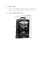
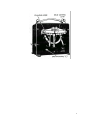
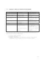
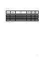
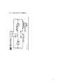
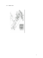
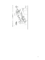
MICRO WELD
MODEL BR/BRG
BUTT WELDERS
MICRO PRODUCTS COMPANY
SERVICE MANUAL
1
TABLE OF CONTENTS
1.0
2.0
3.0
4.0
5.0
6.0
7.0
8.0
9.0
10.0
11.0
12.0
13.0
SPECIFICATIONS
GENERAL OPERATING INSTRUCTIONS
BASIC OPERATING PARTS
BASIC OPERATING PARTS LOCATION
TYPICAL OPERATING SEQUENCE
SPECIAL ADJUSTMENTS
PREVENTIVE MAINTENACE
SUGGESTED SETTINGS
DIAGNOISTIC CHART FOR TROULBE-SHOOTING
ELECTRICAL SCHEMATIC
SAFETY RERMINDERS
BUYERS GUIDE
PARTS LIST
1.0 SPECIFICATIONS
Model BR/BRG
Type of Welding Process
Welding Range
Butt welds
.125 to .500 inch wide flat
stock steel
Material Suitability
Standard Operating Voltages
Steel
115 Volts
Maximum Line Demand 115 Volt
9amps@100% duty cycle
29amps@10% duty cycle
1.5 KVA Maximum
Hand Lever
Bench
Single Phase AC Transformer
Clamp Method
Mounting
Dimensions and Weights
Height Overall
Bench space
Weight
9 in. BR
16 in. BRG
5.5 in. x 9 in.
50 LBS – BR
60 LBS -BRG
2
FEATURES OF WELDING EQUIPMENT
•
•
•
•
•
Stryco quality and workmanship
Heavy-duty construction & components
Easy to operate controls
Low maintenance costs
Easy to set welding parameters
•
•
•
Sensitive straight slide movable headpiece assembly
Adjustable limit switch
Changeable welding dies and clamp shoes
•
•
•
•
Adjustable tension
Manual hand clamps
Low voltage control circuits
Power cord
2.0 GENERAL OPERATING INSTRUCIONS
2.1
ELECTRICAL HOOK-UP INSTRUCTIONS
First determine that available electrical service in your
plant corresponds to the nameplate rating located on welder
housing. Electrical wiring to welder must be of sufficient
size to deliver full ampere load with no appreciable loss
during weld cycle. The welder will not operate properly if
there is more than a 10% variation in the line voltage. In
general, the welder should be fused with a slow blow fuse
of the 100% duty cycle rating. The minimum power cable size
to the welder can be obtained by using this same current
rating.
Refer to National Electrical Code and local electrical
regulations for adequate power sizes; disconnect methods
and fusing guidelines.
Remember line voltages to the welding machine are
potentially dangerous should the power cords be damaged or
severed. The welding voltages at the welding dies will not
harm an operator since they do not exceed 10 volts.
3
2.2
SAFETY PRECAUTIONS
(See section 11.0)
2.2.1 ELECTRICAL
Maintain electrical cable to welder in good repair. Welder
must be grounded and connections securely tightened. Heat
Switch must not be changed to new position while a weld
cycle is in process. Disconnect electrical service before
serving welder – high voltages are located within the base
of the welder.
2.2.2 MECHANICAL
Operator while using welder must wear safety glasses. Keep
all safety guards on welders and use properly. Operators
must be instructed on basic operation of unit to prevent
injury. Check nameplate rating and keep within material
size range for each welder.
2.3
WELDING DIES
The dies and shoes supplied with the welder will handle
most size and material types within the range of the
welder. For new weld applications consult the factory for
special die and shoe sets.
3.0
BASIC OPERATING PARTS
3.1
ALIGNMENT SCREW
An access hole is proved in the left panel for this
adjustment.
3.2
LIMIT SWITCH SETTING
The weld limit switch controls the cut-off point of current
flow to the welding dies. Turning a screw located inside
the welder allows adjustment of the trip point. Access to
this adjustment is with the cover removed.
3.3
OPERATING SWITCH
This switch is located on the front panel.
3.6
UPSET PRESSURE
Upset pressure is required for each weld and is obtained by
a force lever.
4
3.7 CLAMPING SYSTEM
This is a dual system consisting of left and right clamping
devices. The welding dies and shoes, the replaceable
portion of the clamping mechanism, hold the stock to be
joined during the weld cycle.
4.0
BASIC OPERATING PARTS LOCATION
5
6
5.0
TYPICAL OPERATING SEQUENCE
5.1
All insulating materials must be removed from conductors
where they contact welding dies.
5.2
5.3
5.4
Rotate the force lever to proper chart settings.
Trim the stock ends.
Clamp stock end into welding jaw so that it is
approximately midway between open jaws.
5.5 Clamp other stock end into other welding die, so that it
butts and securely contacts first stock end.
5.6 Rotate the force lever to the desired position. Depress the
operating switch. Hold for 1 to 3 seconds to assure a
complete weld cycle.
5.7 Unclamp welded stock.
5.10 ANNEAL OPERATION - If wire is brittle after welding, the
weld zone must be annealed prior to further processing.
One reason the weld zone becomes brittle is because the
carbon within the chemistry of the stock has been adversely
affected. Annealing softening the stock will help
eliminate brittle weld zones. Also when stock has a lot of
previous work hardness imparted to it prior to welding,
annealing spreads the softness of the weld zone over a
greater section.
5.11 UPSET PRESSURE - Upset pressure is required for each weld
and is obtained by the position of a lever located on the
front panel.
5.12 CLAMPING SYSTEM - This is a dual system consisting of left
and right clamping devices. The welding die shoes, the
replaceable portion of the clamping mechanism, holds the
stock to be joined during the weld cycle. The operating
switch located on the front of the welder is used to
activate a weld or anneal cycle.
After annealing remove
the upset burr that has been created by grinding the weld
zone to exact parent metal diameter. Be careful not to
impart stress areas on the wire with grinding scars, which
will lead to breaks. Some users are able to hand file the
weld zone to proper sizes and others prefer the belt
grinder.
5.13 EXPANDED ANNEALING INFORMATION FOR HARD TO PROCESS
MATERIALS
The correct annealing temperature can vary with materials.
Users sometime judge correct anneal temperatures by
watching the wire heat up to a point where the wire breaks
out into black flecks. Then allowing the wire to air cool
to loss of color.
7
Since many carbon steels are ferromagnetic, the exact
anneal temperature can be attained by heating the stock to
a heat range where a permanent magnet is no longer
attracted to the hot heated area. The exact loss of
magnetic attraction corresponds to the exact anneal
temperature for carbon steel. Let material air cool down
prior to removing upset burr.
Annealing should take place immediately after welding cycle
and prior to any burr, removing attempts, to prevent
fracturing welded area. Some users find that an additional
anneal operation is useful after removing the burr on
difficult to join materials.
6.0
6.1
6.2
SPECIAL ADJUSTMENTS
LIMIT SWITCH
The limit switch can be adjusted with the cover removed.
A screw is provided for this.
ALIGNMENT
Adjustment "B" is for correcting alignment of welds.
Turning to right raises and to left lowers left jaw.
A very slight movement of this screw is sufficient.
AN OPERATOR SHOULD WEAR SAFETY GLASSES WHEN USING THIS UNIT.
8
7.0
PREVENTIVE MAINTENANCE TECHNIQUE
Keep in Mind that these welders are precision built to last
many years, but will require good maintenance procedures.
They are designed to be as automatic as possible with a
minimum dependence on the ability of the operator.
Adjustments must be made by those thoroughly familiar with
the operating principles of the welders.
7.1 WELDING DIE NOTES
7.1.1 Welding dies and die shoes in poor condition are the
primary caused of bad welds.
7.1.2 Check die sets for excessive wear and replace if necessary.
7.1.3 Clean weld die bottoms to remove oxides with emery cloth
placed on a flat surface.
7.1.4 Clean die seats with emery cloth to brighten contact areas.
7.1.5 After cleaning of dies be sure to wipe off with soft clean
cloth.
7.1.6 Completely tighten dies into seats to assure a good
contact.
7.1.7 Worn die shoes will not hold stock during a weld cycle,
change steel faces or replace complete shoes.
7.2 WEEKLY
7.2.1 Tighten all loose parts.
7.3 QUARTERLY
7.3.1 Repeat above service items.
7.3.2 Check grease requirements on clamp arms pivot shafts and
lubrication points.
7.3.3 Check anneal parts and replace all worn or broken
assemblies
7.3.4 Check contacts on magnetic contactor for worn contacts.
7.3.5 Clean heat switch contacts with low residue cleaner and
recoat with petroleum jelly.
9
7.4 ANNUALLY
7.4.1 Repeat previously noted items.
7.4.2 Check for wear in clap arm pivots.
7.4.3 Clean inside and outside of welder.
7.4.4 Check grease requirements on headpiece slide shafts, grease
lightly.
7.4.5 Caution: make sure that power supply is disconnected before
servicing welder in anyway!
7.5
WELDING DIES AND DIE SHOES INFORMATION
Description:
Welding dies – Lower conducting electrode and clamp jaw.
Welding die shoes – Upper clamping member.
Welding dies and die shoes in poor condition are the main
causes of bad welds.
Care of die sets:
7.5.1 Use a brass or fiber blade to remove particles of flashings
that build-up on die sets. Excessive flash build-up causes
die burns on material and shorting of die sets.
7.5.2 Do no attempt to clamp material that is not suited for
welder into die sets. Undersize materials will slip and
burn die grooves, oversize materials will overstress
clamping parts.
7.5.3 Do not use welding die sets for a vise.
not withstand the mechanical abuse.
These parts will
7.5.4 Whenever welding dies are replaced, clean bottoms of dies
and corresponding die seats to a bright and clean condition
before bolting them tightly into place. An oxidized
surface will insulate the welding dies and reduce effective
welding voltage.
7.5.5 Welding die shoes must swivel freely within the clamp arm
pivots to prevent cracking of die shoes. File down die
shoe boss if necessary.
7.5.6 Welding die set will wear with use and must be changed
occasionally for good welding results. Keep and adequate
supply of replacement parts available. Stock slippage is a
problem caused by poor die sets and a major cause of
breaks.
10
8.0
SUGGESTED SETTINGS
Recommended settings for Stryco BR/BRG welders.
Material
Size
Model BR/BRG (steel stock)
Steel
.125x.020
Steel
.25x.030
Steel
.50x.030
Steel
.50x.050
Upset Tension
1
1
1
2
Note: These setting are approximate and may be varied to suit
materials and best weld performance.
11
9.0
DIAGNOSTIC CHART FOR TROUBLE-SHOOTING WELDERS
WELDING ACTION
Weld action normal but weld
burr doesn’t extend beyond
stock
Molten metal is blown out
and ends not joined
Weld has complete burr but
is dry and breaks off below
surface of stock
Weld good but poorly aligned
Ends of stock buckle and may
not weld
Varying weld results
CAUSE
Lack of spacing
Weld heat too high
Stock is too small
Low upset pressure
Upset pressure too great
High carbon steel stock
Welding dies & clamps
Starting space
Loose shafts
Upset pressure too great
Low weld heat
Stock slipping
Varying weld voltages
Stock condition variations
Dies
Flashings
REMEDY
Increase starting space
until desired burr is
obtained
Lower heat settings
Check size rating of welder
Adjust upset
Lower upset pressure
Carbon-steel stock often
appears like this, process
by annealing weld before
removing burr
Replace worn dies and clamps
Decrease starting space
Return heads to factory
Decrease starting space
Increase weld heat
Check Clamp pressure
Check electric lines
Clean and tighten
transformer connections to
heads
Clean Stock where clamped in
dies
Replace dies
Clean build-up of flash
materials
Porosity and voids in weld zone may be corrected by using one or
more of the following suggestions.
1. Increase upset pressure.
2. Decrease weld heat
3. Readjust timing point of weld heat cut-off, limit switch
adjustment, to allow heat to cut-off slightly sooner.
12
9.1
ELECTRICAL TROUBLE-SHOOTING OF WELDER
(Caution!! Extreme care should be exercised when making
these tests. Dangerous voltages are present in the welder.
Only persons familiar with electrical safety precautions
should perform these tests.)
9.1.1 TROUBLE-SHOOTING TABLE
(See section 9.1.3)
This electrical trouble-shooting table is furnished as a
suggested method of trouble-shooting the welder. The
individual steps of the table should be performed in the
order given, to make the tests valid. The electrical
schematic (section 10) furnished for these tests show the
table test points. The table may be used for welders with
a different but closely related wiring by using
corresponding test points. During all tests, line voltage
should be connected to L1 & L2 of the welder.
9.1.2 FINAL ELECTRICAL CHECKS
Connect the voltmeter across the welding dies. Press the
operating switch. The meter reading will typically be less
than 10 VAC. Consult the weld specification sheet for this
value.
Actuate the weld limit switch; observe the
reading goes to zero. Release the weld limit and operating
switches, the reading should remain at zero.
13
9.1.3
TEST LEAD
CONNECTION
METER
READING
PROBLEM
IF NO
READING
PRESS
OPERATING
SWITCH
WELD
LIMIT
SWITCH
ACTUATED
PRESS
ANNEAL
SWITCH
115 VOLT ONLY.REFERENCE TO 9.1.1.
L2
L2
L2
L2
PB1-1
PB1-2
LS1-1
LS1-2
L2 T1-1
115
115
115
115
VAC
VAC
VAC
VAC
115 VAC
Open wire to operating switch
Bad operating switch
Open wire to weld limit switch
Open weld limit switch
X
X
X
Open wire to transformer
X
NOTE: To perform repair consult section 13 for parts
identification.
14
10.0 ELECTRICAL SCHEMATIC
15
11.0 SAFETY REMINDERS
The following accident prevention information is presented
to eliminate potential hazards while operating, inspecting
or repairing Micro-Weld electric resistance welding
equipment.
Important safety compliance information for Micro-Weld
Welders.
GENERAL
1. Qualified personnel, prior to using equipment, must
instruct an operator on basic operation and
malfunction methods.
2. Safety eyeglasses must be worn by all personnel
operating or servicing welders.
3. Use safety equipment properly and keep safety
equipment on welders.
4. Determine that both operating voltages and hertz
(cycles) of power supply correspond to ratings listed
on welder nameplate located on welder housing.
5. Check nameplate ratings and keep within capacities and
material categories stated therein.
6. Adjustments or repairs must be made by persons
thoroughly familiar with operating principles of
welder.
7. Welder must be disconnected from power supply prior to
maintenance or repair procedures.
ELECTRICAL
1. Refer to National Electrical Code and local
regulations for adequate electrical wiring to power
welder. Do not operate welder with inadequate
electrical power supply cords or cable.
2. All welders must be grounded through power supply and
welder ground connection terminal securely tightened.
3. All welders must be able to be disconnected from power
source either by a double breaking disconnect switch
or unplugged by standard rated plugs.
4. All welders must be fused to prevent injury should an
electrical malfunction occur. Welders must never be
fused for an ampere load that exceeds the ratings
stated on welder nameplate. Normally welders are
fused using the nameplate rated load; time lag
parameters functional to standard fuses allow this
specification.
5. Electric power cords to welder must be kept in good
condition. Report any damage or potential hazards to
maintenance personnel.
6. The weld heat selection switch, potentiometer or range
selection devices must not be changed to a new
position while a weld operation is in process.
16
12.0 BUYERS GUIDE
HOW TO ORDER PARTS:
You must provide
1. Machine Model
2. Machine Serial Number
3. Voltage
Then identify part(s) on part list (last page in book) and
provide STRYCO with the circled number.
CALL STRYCO at 800-872-1068
OR FAX STRYCO at 630-787-9360
Provide STRYCO with your company name and purchase order
number.
17
13.0 PARTS LIST
18
19
20


![Manual[DOWNLOAD]](http://vs1.manualzilla.com/store/data/005897454_1-7b43247b19e54aa42c3777609ebafaf8-150x150.png)