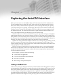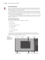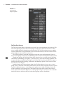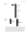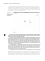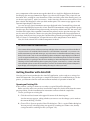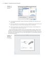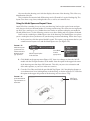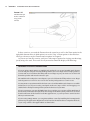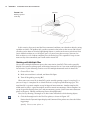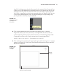
1
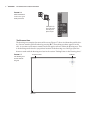
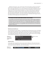
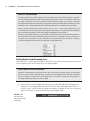
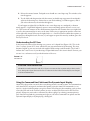
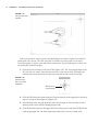
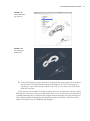
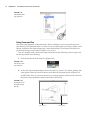
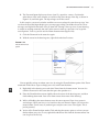
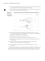
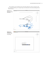
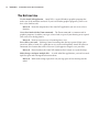
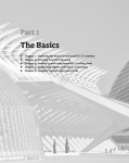
Part 1 RI PY RI GH TE D MA TE Chapter 1: Exploring the AutoCAD Interface Chapter 2: Creating Your First Drawing Chapter 3: Setting Up and Using AutoCAD’s Drafting Tools Chapter 4: Organizing Objects with Blocks and Groups Chapter 5: Keeping Track of Layers and Blocks CO u u u u u AL The Basics Chapter 1 Exploring the AutoCAD Interface Before you can start to use AutoCAD for Mac, you’ll need to become familiar with the basics. If you’re completely new to AutoCAD, you’ll want to read this first chapter carefully. It introduces you to many of AutoCAD’s basic operations, such as opening and closing files, getting a close-up look at part of a drawing, and changing a drawing. If you’re familiar with the latest Windows version of AutoCAD, you should review this chapter anyway to get acquainted with the Macintosh version. The AutoCAD Mac interface is quite different from the Windows version, so this chapter will help you find the tools you are familiar with. Autodesk releases new versions of AutoCAD every year. Part of this strategy is to introduce improvements that focus on a particular category of features. This latest version, AutoCAD for Mac, includes several new features that are related to curves in both 2D drafting and 3D modeling. There are also a number of enhancements that allow you to easily select similar objects in a drawing. The ability to make objects appear transparent has also been improved. Autodesk has discovered that the number of 3D users is on the upswing, so with this version, you’ll see some new 3D features that will give you more freedom to create 3D shapes. These features include some new ways to create surface forms and the editing tools that enable you to easily manipulate 3D solids and surfaces. You’ll get a chance to explore these new features and many more as you work through this book. Before you begin the exercise later in this chapter, make sure that you have loaded the sample files from this book’s companion website, www.sybex.com/go/masteringautocadmac. See the introduction for details. In this chapter, you’ll learn to do the following: •u Use the AutoCAD application •u Get a closer look with the Zoom command •u Save a file as you work •u Make changes and open multiple files Taking a Guided Tour In this section, you’ll get a chance to familiarize yourself with the AutoCAD application and how you communicate with AutoCAD. As you do the exercises in this chapter, you’ll also get a feel for how to work with this book. Don’t worry about understanding or remembering everything you see in this chapter. You’ll get plenty of opportunities to probe the finer details of the program as you work through the later chapters. To help you remember the material, you’ll find a brief set of questions at the end of each chapter. For now, just enjoy your first excursion into AutoCAD. 4 | Chapter 1 Exploring the AutoCAD Interface Launching AutoCAD If you have already installed AutoCAD (see Appendix B on the book's website) and are ready to jump in and take a look, click the AutoCAD icon in the Dock. AutoCAD opens and displays a blank default document named Drawing1.dwg. If you’re using the trial version, you’ll see the Product License Activation window after you click the AutoCAD icon. This window shows you the number of days you have left in the trial version. It also enables you to activate the product if you purchase a license. Click the Try button to continue to the blank default document. Now let’s look at the AutoCAD application in detail. Don’t worry if it seems like a lot of information. You don’t have to memorize it, but by looking at all the parts, you’ll be aware of what is available in a general way. The AutoCAD Application The AutoCAD program window is divided into seven parts: •u Menu bar •u Layers palette •u Properties Inspector palette •u Tool Sets palette •u Drawing area •u Command Line palette •u Status bar Figure 1.1 shows a typical layout of the AutoCAD application. You can organize the AutoCAD palettes into any arrangement you want, but while you’re learning AutoCAD you may want to leave the default arrangement in place. Figure 1.1 Tool Sets palette Menu bar Drawing area Layers palette Status bar Properties Inspector palette A typical arrangement of the AutoCAD application Command Line palette | Taking a Guided Tour 5 The Menu Bar Like a typical Mac application, AutoCAD displays a menu bar where you can select a command to perform a task. As you work through this book, you’ll be directed to choose commands from the menu bar where appropriate. Often commands in the menu bar are repeated as tools in the Tool Sets palette, so I’ll direct you to select a tool from the Tool Sets palette or a command from the menu bar and you can decide which method you prefer. You’ll learn about the Tool Sets palette a bit later. The Layers Palette The Layers palette (Figure 1.2) displays the layer information in the current drawing. Layers help you organize your drawing. If you’ve used Photoshop or other drawing programs that employ layers, you’re probably familiar with the basic concept of layers. You can separate parts of a drawing into layers and then control the display of those parts by adjusting layer properties. You’ll learn more about layers in Chapter 5, “Keeping Track of Layers and Blocks.” Figure 1.2 The Layers palette Click the disclosure triangle to expand or contract the Layers palette. The Properties Inspector Palette The Properties Inspector palette (Figure 1.3) displays information about the layers and objects in your drawing. When you select a layer name from the Layers palette, the layer’s properties are displayed in the Properties Inspector palette. When you draw lines, circles, and other objects, you can use the Properties Inspector palette to display the properties of those objects. You’ll learn more about object properties in Chapter 2, “Creating Your First Drawing.” 6 | Chapter 1 Exploring the AutoCAD Interface Figure 1.3 The Properties Inspector palette The Tool Sets Palette The Tool Sets palette (Figure 1.4) contains tools you’ll use to create and edit your drawings. The tools in the palette give you a clue to their purpose, and you can hover the cursor over a tool to see a tooltip showing a descriptive name of the tool. The Tool Sets palette gives you a quick, one-click method for issuing commands. You’ll also find that many of the tools in the Tool Sets palette duplicate commands in the menu bar. The Tool Sets palette is organized into groups of tools that serve similar functions. Figure 1.4 shows the tool groups; some can be expanded into panels, which are described later in this section. Though not obvious, the Tool Sets palette offers three tool sets, or workflow panels: Drafting, Annotation, and Modeling (see Figure 1.4). The one you see now is the Drafting workflow. You can open the other workflows by clicking the tool in the Tool Sets palette title bar. This opens a pop-up menu offering the Drafting, Annotation, and Modeling options. You’ll use these other sets of tools in later chapters. Another feature you’ll want to know about is the Tool Sets palette tool group arrow. A tool group arrow is similar to a menu bar option because you can click a tool group arrow to expand a panel of additional options. A tool group arrow appears to the right of a group of tools that can be expanded to a tool group panel. Clicking the tool group arrow expands the palette to reveal a panel with more tools (Figure 1.5). A tool group arrow gives you access to a set of additional tools that are similar to the set of tools the tool group arrow is attached to. | Taking a Guided Tour 7 Figure 1.4 Tool Sets icon The Tool Sets palette Select/Select Similar Open Shapes Closed Shapes Block Explode/Erase Move/Rotate/Scale/Stretch Copy/Array Mirror/Offset Modify Parametric Distance/Area Coordinates Figure 1.5 A Tool Sets tool group and tool group arrow Click a tool group arrow. A tool group panel appears. Some of the tools in the Tool Sets palette contain more than one option. For example, if you click and hold the Circle tool (labeled as Center, Radius on its help tag), you will see additional tools in a column below the tool (Figure 1.6). This set of additional tools is called a flyout. You can tell if a tool opens a flyout if you see a small triangle in the lower-right corner of the icon (Figure 1.6). Flyouts offer additional ways to use a tool. For example, the Circle tool flyout lets you draw a circle by specifying a center and radius, a center and diameter, 2 points, 3 points, two tangent points and a radius, or three tangent points. The flyouts often mimic the options in the menu bar. If you click Draw Circle, you will see the same options appear in the flyout menu. 8 | Chapter 1 Exploring the AutoCAD Interface Figure 1.6 Click and hold the circle tool to open the flyout menu. A triangle in the lower right of the tool tells you it opens a flyout. The Drawing Area The drawing area occupies the center of the screen. Figure 1.7 shows it without the grid for clarity. (You can turn the grid off and on by pressing F-G.) Everything you draw appears in this area. As you move your mouse around, crosshairs appear to move within the drawing area. This is the drawing cursor that lets you point to locations in the drawing area. You’ll get your first chance to work with the drawing area later in the section “Picking Points in the Drawing Area.” Figure 1.7 Viewport controls The drawing area shown without the grid UCS icon ViewCube | Taking a Guided Tour 9 Within the drawing area, you see three items. The UCS icon appears in the lower-left corner. You’ll learn more about the UCS icon in a moment (see the section “Understanding the UCS Icon”). In the upper-right corner, you see the ViewCube. The ViewCube is primarily for 3D modeling, and you’ll learn more about it in Chapter 19, “Creating 3D Drawings.” In the upper-left corner you see the viewport controls. In Figure 1.7 they show a plus sign and the words Top, and 2D Wireframe. The plus sign offers viewport options that you’ll learn about in Chapter 20, “Using Advanced 3D Features.” The other two options change depending on the way your drawing is displayed. You’ll get a closer look at these options a bit later in this chapter. For now, let’s continue examining the parts of the AutoCAD screen. Why Does the Drawing Area Look Different on My Screen? You probably noticed that the drawing area shown in this book has a white background while the drawing area in your version of AutoCAD shows a dark gray background. I’m using a white background in the book to make things easier to see on a printed page. White lines on a dark background do not print very well. You can also change your drawing area background to white using the AutoCAD Application Preferences. See Appendix B on the book's website for more on the AutoCAD Application Preferences. The Command Line Palette The Command Line palette (Figure 1.8), located just below the drawing area, gives you feedback about AutoCAD’s commands as you use them. You can move and resize this palette just as you move and resize other palettes and windows on the Mac. For example, you can click the disclosure triangle (more commonly called the disclosure triangle, which is the term I’ll use throughout this book) on the right side to expand and contract the palette. Figure 1.8 Disclosure triangle The expanded Command Line palette The Status Bar To the right of the Command Line palette is the status bar (Figure 1.9). The tools in the status bar offer aids to the drafting process. You’ll find tools to turn on the grid and snap functions as well as tools to help you control the scale of text and symbols. Figure 1.9 The status bar 10 | Chapter 1 Exploring the AutoCAD Interface Tools vs. the Keyboard Throughout this book, you’ll be told to select tools from the Tool Sets palette to invoke commands. For new and experienced users alike, the Tool Sets palette offers an easy-to-remember method for accessing commands. If you’re an experienced AutoCAD user, though, you can type commands directly from the keyboard. The keyboard commands you know and love still work as they do in the Windows version of AutoCAD (but with the key used in place of the Windows Control key). Many tools and commands have aliases. Aliases are one-, two-, or three-letter abbreviations of a command name. As you become more proficient with AutoCAD, you may find these aliases helpful. As you work through this book, the aliases will be identified for your reference. Finally, in typical Mac fashion, you can find the command shortcuts in the pull-down menus of the menu bar. Shortcuts are multiple key presses that start a command or change a feature. For example, you can press -1 to open or close the Tool Sets palette. If you choose Tools Palettes, you’ll see the keyboard shortcuts to the right of the command names. Picking Points in the Drawing Area Now that you’ve seen the general layout of AutoCAD, take a look at the drawing cursor to get a sense of how the parts of the AutoCAD screen work together: Click a Mouse or Tap a Trackpad? This book assumes that you are using a mouse. If you are using a trackpad, use the corresponding gestures to issue a click, a click-and-drag, or a right-click. For example, a mouse click is a one-finger tap on a trackpad. A right-click is a two-finger tap on a trackpad. A click-and-drag requires a one-finger double-tap and drag on the trackpad. 1. Place the cursor in the middle of the drawing area and click and hold. Trackpad users should use a one-finger double-tap. Move the mouse and a rectangle follows. This is a selection window; you’ll learn more about this window in Chapter 2. You also see Specify opposite corner: in the Command Line palette (Figure 1.10). Figure 1.10 The Command Line palette shown un-docked | Taking a Guided Tour 11 2. Release the mouse button. Trackpad users should use a one-finger tap. The window selection disappears. 3. Try the click-and-drag motion with the mouse (or double-tap, tap gesture for trackpads) again in the drawing area. Notice that as you click and drag, a window appears, and as you release the mouse, the window disappears. If you happen to right-click (or -click or use a two-finger tap on a trackpad), a shortcut menu appears. A right-click frequently opens a menu containing options that are context sensitive. This means the contents of the shortcut menu depend on the location where you right-click as well as the command that is active at the time. If there are no appropriate options at the time of the right-click, AutoCAD treats the right-click as a ↵. You’ll learn more about these options as you progress through the book. For now, if you happen to open this menu by accident, press the Esc key to close it. Understanding the UCS Icon In the lower-left corner of the drawing area, you see an L-shaped line (Figure 1.11). This is the User Coordinate System (UCS) icon, which tells you your orientation in the drawing. This icon becomes helpful as you start to work with complex 2D drawings and 3D models. The X and Y indicate the X and Y axes of your drawing. Chapter 20 discusses this icon in detail. For now, you can use it as a reference to tell you the direction of the axes. Figure 1.11 The UCS icon If You Can’t Find the UCS Icon The UCS icon can be turned on and off, so if you’re on someone else’s system and you don’t see the icon, don’t panic. If you don’t see the icon or it doesn’t look as it does in this chapter, see Chapter 20 for more information. Using the Command Line Palette and the Dynamic Input Display AutoCAD is the perfect servant: It does everything you tell it to and no more. You communicate with AutoCAD by using tools and menu bar options to invoke AutoCAD commands. A command is a single-word instruction you give to AutoCAD telling it to do something, such as draw a line (the Line tool in the Tool Sets palette) or erase an object (the Erase tool in the Tool Sets palette). Whenever you invoke a command, by either typing it or selecting a menu option or tool, AutoCAD responds by presenting messages to you in the Command Line palette and the Dynamic Input display or by displaying a dialog box. 12 | Chapter 1 Exploring the AutoCAD Interface The Dynamic Input display allows you to enter dimensional data of objects as you draw them. Besides echoing the Command Line palette messages, the Dynamic Input display shows temporary dimensions, coordinates, and angles of objects you’re drawing and editing. As you enter coordinate or angle values through the keyboard, they appear in the Dynamic Input display, which is connected to the cursor (Figure 1.12). Figure 1.12 A sample of how the Dynamic Input display looks You can easily turn the Dynamic Input display on or off by clicking the Dynamic Input tool in the status bar. When the Dynamic Input display is turned off, responses to your keyboard input appear only in the Command Line palette. The messages in the Command Line palette, or in the Dynamic Input display, often tell you what to do next. Commands may also display a list of options in the Command Line palette. A single command often presents a series of messages, which you answer to complete the command. These messages serve as an aid to new users who need a little help. If you ever get lost while using a command or forget what you’re supposed to do, look at the Command Line palette for clues. As you become more comfortable with AutoCAD, you’ll find that you won’t need to refer to these messages as frequently. As an additional aid, you can right-click to display a context-sensitive shortcut menu. That is, if you’re in the middle of a command, the context-sensitive menu displays a list of options specifically related to that command. For example, if you right-click before picking the first point for the Rectangle command, a menu opens, displaying the same options that are listed in the Command Line palette plus some additional options. As mentioned, the Command Line palette is located in the bottom left of the AutoCAD application. By default, it shows a single line of text. You can expand the Command Line palette by clicking the disclosure triangle, which, as mentioned earlier, is the triangle icon on the right side of the palette. The expanded Command Line palette shows several lines. The bottom line shows the current messages, and the top lines show messages that have scrolled by or, in some | Getting Familiar with AutoCAD 13 cases, components of the current message that don’t fit in a single line. Right now, the bottom line displays the message Command (see Figure 1.8, earlier in this chapter). This prompt tells you that AutoCAD is waiting for your instructions. When you click a point in the drawing area, you see the message Specify opposite corner:. At the same time, the cursor starts to draw a window selection that disappears when you click another point. The same message appears in the Dynamic Input display at the cursor. As a new user, pay special attention to messages displayed in the Command Line palette and the Dynamic Input display because this is how AutoCAD communicates with you. Besides giving you messages, the Command Line palette records your activity within AutoCAD. You can use the scroll bar to the right of the expanded Command Line palette to review previous messages. You can also resize the palette for a better view using the resizing handle in the lower-right corner of the palette. And you can close or open the Command Line palette by pressing -3 or by choosing Tools Palettes Command Line. (Chapter 2 discusses these components in more detail.) Now, let’s look at AutoCAD’s window components in detail. Do I Really Need the Command Line? The Command Line palette and the Dynamic Input display allow AutoCAD to provide text feedback on your actions. You can think of these features as a chat window to AutoCAD—as you enter commands, AutoCAD responds with messages. As you become more familiar with AutoCAD, you may find you don’t need to rely on the Command Line palette and Dynamic Input display for feedback. If you’re an experienced Mac user, you might think of the Command Line palette as a kind of terminal window that lets you get deeper into the inner workings of AutoCAD. Experienced users can take advantage of the Command Line palette to query the program, create macros, or enter commands and command options. For new and casual users, however, the Command Line palette and Dynamic Input display can be helpful in understanding what steps to take as you work. Getting Familiar with AutoCAD Now that you’ve been introduced to the AutoCAD application, you’re ready to try using a few AutoCAD commands. First you’ll open a sample file and make a few modifications to it. In the process, you’ll become familiar with some common methods of operation in AutoCAD. Opening an Existing File In this exercise, you’ll get a chance to see and use a typical Select File dialog box. Before you start, make sure you have installed the sample files for this book from the accompanying website. See the introduction for instructions on how to find the sample files. To start, you’ll open an existing file: 1. Click the red close button in the upper-left corner of the drawing area. An alert message appears, asking whether you want to save the changes you’ve made to the current drawing. Click No. 2. Choose File Open to open the Select File dialog box. This is a typical Finder dialog box. You can preview a drawing before you open it by switching to a column view, thereby saving time while searching for files (see Figure 1.13). 14 | Chapter 1 Exploring the AutoCAD Interface Figure 1.13 The Select File dialog box 3. In the Select File dialog box, navigate to the Chapter 01 folder of the sample files you downloaded. 4. Select clip.dwg. The Preview column now shows a thumbnail image of the file. Be aware that a thumbnail may not show for files from older releases of AutoCAD. 5. Click the Open button at the bottom of the Select File dialog box. AutoCAD opens the clip.dwg file, which is shown in Figure 1.14. The clip.dwg file opens to display a layout view of the drawing. A layout is a type of view in which you lay out different views of your drawing in preparation for printing. You can tell you are in a layout view by the white area over the gray background. This white area represents your drawing on a printed page. This view is like a print preview. See the following section for more on the layout views. Figure 1.14 The Layout1 view of the clip.dwg file | Getting Familiar with AutoCAD 15 Also note that the drawing area’s title bar displays the name of the drawing. This offers easy identification of the file. This particular file contains both 2D drawings and a 3D model of a typical locking clip. The layout view shows a top, front, and right-side view as well as an isometric view. Using the Model Space and Layout Views AutoCAD offers a number of ways to view your drawing. You have the typical zoom and pan tools, but you also have different modes of viewing your drawing. The two main viewing modes are Model Space and layout views. Within these two modes are options to display your model in 3D and shaded views. Try the following exercise to see these modes and view options firsthand. You’ll start by switching to a Model Space view of the drawing. The Model Space view places you in a workspace where you do most of your drawing creation and editing. Follow these steps: 1. In the status bar, click the option labeled Layout1. This opens a pop-up menu that lets you switch between layout views and the Model Space view (see Figure 1.15). Figure 1.15 Click the Layout1 option in the status bar and select Model from the pop-up menu. Click the Layout1 option in the status bar. Select Model from the pop-up menu. 2. Click Model on the pop-up menu (Figure 1.15). Your view changes to show the full 3D model with the 2D representations of the model. Note the option in the upper-left corner of the drawing area that shows SW Isometric. This tells you your view orientation and offers other options, as you’ll see in the next exercise. 3. Go to the ViewCube and click the part labeled Top (Figure 1.16). Your display changes to a two-dimensional view looking down on the drawing, as shown in Figure 1.17. Note that the option in the upper-left portion of the drawing area now shows "Top." Figure 1.16 3D model with 2D representations of the model Click Top on the ViewCube. 16 | Chapter 1 Exploring the AutoCAD Interface Figure 1.17 The Top view of the drawing You’ve just seen how you can get into the Model Space view from a layout view and then switch from a 3D view to a 2D view using the ViewCube. Let’s take a look at a few more ViewCube options as well as some other view-related tools. Try the following to see how you can control the AutoCAD display: 1. Click the lower-left corner of the ViewCube (Figure 1.18). The view changes back to the 3D view you saw earlier. Note that you can now see the corner of the ViewCube you clicked as the corner that intersects the left, front, and top sides of the ViewCube. Figure 1.18 Click the lowerleft corner of the ViewCube. Click this corner of the ViewCube. 2. Click the 2D Wireframe option from the Viewport controls in the upper left of the drawing area. A pop-up menu appears (Figure 1.19). 3. Select Realistic from the pop-up menu. Your view changes to show the 3D part of the drawing with a more realistic shading (Figure 1.20). 4. Click the Realistic option in the upper left of the drawing area and select 2D Wireframe from the pop-up menu. The drawing changes back to the view you started with. | Getting Familiar with AutoCAD 17 Figure 1.19 The 2D Wireframe pop-up menu Figure 1.20 The drawing in a shaded view 5. Click the SW Isometric option from the Viewport controls in the upper left of the drawing area, then select Top from the pop-up menu (Figure 1.21). The view changes to a “top-down” view of the drawing, similar to the view you saw when you selected Top from the ViewCube. In this exercise, you used the ViewCube to change your view orientation to a 3D view called SW Isometric. You also saw how you could change your view to one that shows the 3D object in a shaded mode using the Viewport controls pop-up menu in the upper left of the drawing area. These different modes of displaying your drawing are called Visual Styles. You’ll learn more about Visual Styles in Part 4, “Modeling and Imaging.” 18 | Chapter 1 Exploring the AutoCAD Interface Figure 1.21 The SW Isometric pop-up menu Using Zoom and Pan One of the most frequently used commands is Zoom, which gives you a closer look at part of your drawing. This command offers a variety of ways to control your view. In this section, you’ll enlarge a portion of the clip drawing to get a more detailed look. To tell AutoCAD which area you want to enlarge, you use what is called a zoom window. Now let’s continue with a look at the Zoom command. Try the following exercise to get a feel for moving around in the drawing: 1. Click the Zoom tool in the status bar (Figure 1.22). Figure 1.22 The Zoom tool in the status bar 2. At first, the Dynamic Input display shows the Specify corner of window: prompt with some options. Move the crosshair cursor to the lower-left location shown in Figure 1.23, and then click. Now as you move the cursor, a rectangle appears with one corner fixed on the point you just picked; the other corner follows the cursor. Figure 1.23 Placing the zoom window around the clip First click here... ...then click here. | Getting Familiar with AutoCAD 19 3. The Dynamic Input display now shows Specify opposite corner:. Position the other corner of the zoom window so it encloses the lower image of the clip, as shown in Figure 1.23, and click again. The clip enlarges to fill the screen. In this exercise, you used a window to define an area to enlarge for your close-up view. You saw how the Dynamic Input display gave you messages to help you decide what to do. These messages are helpful for first-time users of AutoCAD. Getting a close-up view of your drawing is crucial to working accurately, but you’ll often want to return to a previous view to get the overall picture. To do so, you can use the Zoom shortcut menu (Figure 1.24): 1. Click the Zoom tool in the status bar again. 2. With the cursor in the drawing area, right-click and select Previous. Figure 1.24 The Zoom Previous option You can quickly enlarge or reduce your view by using the Zoom Realtime option of the Zoom command. Follow these steps to change your view with Zoom Realtime: 1. Right-click in the drawing area and select Zoom from the shortcut menu. You can also 2. Place the Zoom Realtime cursor slightly above the center of the drawing area, and then click the Zoom tool in the status bar then press the spacebar or ↵. click and drag downward. Your view zooms out to show more of the drawing. 3. While still holding the mouse button, move the cursor upward. Your view zooms in and enlarges. When you have a view similar to the one shown in Figure 1.25, release the mouse button. (Don’t worry if you don’t get exactly the same view as the figure. This is just for practice.) 4. You’re still in Zoom Realtime mode. Click and drag the mouse again to see how you can further adjust your view. To exit, right-click and choose Exit from the shortcut menu. You can also press the Esc key. 20 | Chapter 1 Exploring the AutoCAD Interface Figure 1.25 The final view you want to achieve in step 3 of the exercise In these exercises, you used the Zoom tool on the status bar as well as the Zoom option in the right-click shortcut menu. A third option is to use the View Zoom options in the menu bar. You’ll get a chance to try the Zoom menu bar options in Chapter 2. As you can see from this exercise, you have a wide range of options for viewing your drawings, just by using a few tools. These tools are all you need to control the display of 2D drawings. Using Multi-Touch to Zoom and Pan If you are using a Magic Mouse or a Multi-Touch trackpad, you can use its Multi-Touch feature to zoom and pan over your view. On the Magic Mouse, use a one-finger vertical swipe gesture to zoom in and out or hold down the key and use one finger to pan your view. You can also hold down the spacebar and move the mouse to pan. On a Multi-Touch trackpad, use two fingers to pan or hold down the key and use a two-finger vertical gesture to zoom in or out. You can also use the pinch gesture to zoom in or out. You may want to experiment with both the Zoom tool and the Multi-Touch feature to see which works best for you. If you are using a trackpad, make sure “Tap to Click” and “Dragging” are enabled in the Trackpad settings in the System Preferences for your Mac. If you’re a new user, you may find Multi-Touch too sensitive. You can turn off the Multi-Touch Scroll and Zoom features through the mouse settings in the OS X system preferences. Be aware that this will turn off the feature for all Mac applications, so you may want to turn it back on when you exit AutoCAD. If you’re using a Magic Mouse, you can gain much finer control by installing the free MagicPrefs preference pane application. MagicPrefs can be found on the website that accompanies this book, or you can go online to the Apple website to download it. | Getting Familiar with AutoCAD 21 Saving a File as You Work It’s a good idea to save your file periodically as you work on it. You can save it under its original name (choose File Save from the menu bar) or under a different name (choose File Save As from the menu bar), thereby creating a new file. By default, AutoCAD automatically saves your work at 10-minute intervals under a name that is a combination of the current filename plus a number and that ends with the .sv$ filename extension; this is known as the Automatic Save feature. Using settings in the Application Preferences dialog box or AutoCAD system variables, you can change the name of the autosaved file and control the time between autosaves. See the section “The Look & Feel Options” in Appendix B on the accompanying website for details. “I Can’t Find My Automatic Saves!” As an IT manager at ELS Architecture and Urban Planning, one of the most common questions I get is “Where does AutoCAD put the Automatic Save files?” By default, the Automatic Save file is stored in the Macintosh HD/Private/tmp folder. You can find the exact location for your system by typing Savefilepath↵ in the Command Line palette. The location is displayed in the Command Line palette and in the Dynamic Input display. This file location is often set as a hidden folder, but you can get to it using the Go To Folder command. While in the Finder, press Shift--G. In the Go To Folder dialog box, enter /tmp and click Go. You can also specify a different location for the Automatic Save files. See Appendix B on the accompanying website for information on how to locate hidden files and specify a location for your files. Making Changes You’ll frequently make changes to your drawings. One of AutoCAD’s primary advantages is the ease with which you can make changes. The following exercise shows you a typical sequence of operations involved in changing a drawing: 1. Use the Save As option in the File menu to save the current clip.dwg file under the name MyFirst. For convenience, you can save your files in the Documents folder. 2. Make sure you are in the Drafting workflow, then from the Tool Sets palette, click the Erase tool (the one with a pencil eraser touching paper). This activates the Erase command. Notice that the cursor has turned into a small square. This square is called the pickbox. You also see Select objects: in the Command Line palette and the Dynamic Input display. This message helps remind new users what to do. 3. Place the pickbox on the crosshatch pattern of the clip (see Figure 1.26) and click. The crosshatch changes in appearance to a light highlight. The pickbox and the Select objects: prompt remain, indicating that you can continue to select objects. 4. Right-click and select Enter, or press ↵ or the spacebar. The crosshatch disappears. You’ve just erased a part of the drawing. 22 | Chapter 1 Exploring the AutoCAD Interface Figure 1.26 Click here. Erasing a portion of the clip In this exercise, first you issued the Erase command, and then you selected an object by using a pickbox to click it. The pickbox tells you that you must select items on the screen, and it shows you what you’re about to select by highlighting objects as you hover the cursor over them. Once you’ve clicked an object or a set of objects, press ↵ to move on to the next step. (You can also click an object or a set of objects and then press the Delete key.) This sequence of steps is common to many of the commands you’ll work with in AutoCAD. Working with Multiple Files You can have multiple documents open at the same time in AutoCAD. This can be especially helpful if you want to exchange parts of drawings between files or if you want another file open for reference. Try the following exercise to see how multiple documents work in AutoCAD: 1. Choose File New. 2. Make sure acad.dwt is selected, and then click Open. 3. Turn off the grid by pressing -G. When you create a new file in AutoCAD, you’re actually opening a copy of a template file, as you saw in step 1. A template file is a blank file that is set up for specific drawing types. The acad.dwt file is a generic template set up for Imperial measurements. Another template file, called acadiso.dwt, is a generic template useful for metric measurements. Other templates are set up for specific drawing-sheet sizes and measurement systems. You’ll learn more about templates in Chapter 6, “Editing and Reusing Data to Work Efficiently.” Next, let’s try drawing a rectangle to see how AutoCAD behaves while drawing objects: 1. Click the Rectangle tool in the Tool Sets palette, as shown in Figure 1.27. Notice that the Dynamic Input display and Command Line palette now show the following prompt: Specify first corner point or | Getting Familiar with AutoCAD 23 AutoCAD is asking you to select the first corner for the rectangle. In the Command Line palette you see some additional text in brackets offering a few options that you can take advantage of at this point in the command. Don’t worry about those options right now. You’ll have an opportunity to learn about command options in Chapter 2. Note that you can view the command options at the Dynamic Input display by right-clicking or by pressing the down arrow key on your keyboard. Figure 1.27 Click the Rectangle tool in the Tool Sets palette. 2. Click a point roughly in the lower-left corner of the drawing area, as shown in Figure 1.28. Now, as you move your mouse, a rectangle follows the cursor, with one corner fixed at the position you just selected. You also see the following prompt in the Command Line palette, with a similar prompt in the Dynamic Input display: Specify other corner point or [Area/Dimensions/Rotation]: 3. Click another point anywhere in the upper-right region of the drawing area. A rectangle appears (see Figure 1.28). You’ll learn more about the different cursor shapes and what they mean in Chapter 2. Figure 1.28 Drawing the rectangle Click here to finish it. Click here to start the rectangle. 24 | Chapter 1 Exploring the AutoCAD Interface 4. Let’s try copying objects between these two files. Click in the window with the clip drawing to make it active. You can also choose Window Clip.dwg. 5. Click the Zoom tool in the status bar, right-click, and select All from the shortcut menu to get an overall view of the drawing (see Figure 1.29). Figure 1.29 The Zoom All option gives you an overall view of your drawing. 6. Click the 2D version of the clip at the bottom of the drawing to select it. A series of squares and arrows appears on the drawing. These are called grips (see Figure 1.30), and you’ll learn more about them in the next chapter. 7. Right-click and select Clipboard Copy or press -C. 8. Click inside the other drawing window, Drawing 2.dwg, to make it active. 9. Right-click and select Clipboard Paste or press -V. The clip appears at the cursor in the new drawing. 10. Position the clip in the middle of the rectangle you drew earlier and left-click (Figure 1.31). The clip is copied into the second drawing. 11. Save the new file as My Clip and then exit AutoCAD. You don’t have to save the clip.dwg file. You can have as many files open as you want as long as your computer has adequate memory to accommodate them. You can control the individual document windows as you would any window, using the window control buttons in the upper-left corner of the document window. | Getting Familiar with AutoCAD 25 This concludes your introduction to the AutoCAD application. In the next chapter, you’ll try your hand at drawing a few simple shapes and using some of the other drafting tools that AutoCAD offers. Figure 1.30 Grips shown in the 2D drawing Figure 1.31 Pasting the clip drawing into the new drawing 26 | Chapter 1 Exploring the AutoCAD Interface The Bottom Line Use the AutoCAD application. AutoCAD is a typical Windows graphics program that makes use of the menu bar and tools. If you’ve used other graphics programs, you’ll see at least a few familiar tools. Master It Name the components of the AutoCAD application you can use to select a function. Get a closer look with the Zoom command. The Zoom command is a common tool in graphics programs. It enables you to get a closer look at a part of your drawing or to expand your view to see the big picture. Master It Name at least two ways of zooming into a view. Save a file as you work. Nothing is more frustrating than having a power failure cause you to lose hours of work. It’s a good idea to save your work frequently. AutoCAD offers an Automatic Save feature that can be a lifesaver if you happen to forget to save your files. Master It How often does the AutoCAD Automatic Save feature save your drawing? Make changes and open multiple files. As with other Mac applications, you can have multiple files open and exchange data between them. Master It With two drawings open, how can you copy parts of one drawing into the other?