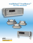
1
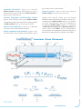
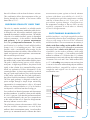
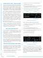
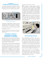
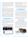
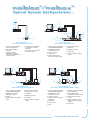
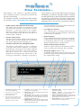
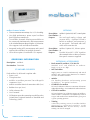
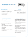
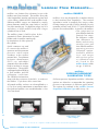
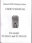
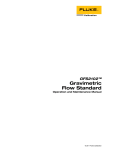
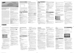
Gas Flow Standards F Fllo ow w C Ca alliib brra attiio on n S Sy ys stte em m INTRODUCTION... INTRODUCTION... In the early 1990s, DHI recognized the growing need for a new calibration tool for low gas flows. To support increasing requirements for lower measurement uncertainties and TABLE OF CONTENTS documented traceability of flow measurements at the process level, a transfer standard combining high performance with portability INTRODUCTION 1 GENERAL FEATURES 3 PUTTING TOGETHER A molbloc/molbox FLOW CALIBRATION SYSTEM 8 and ease of use was needed. DHI developed the molbloc/molbox flow calibration system in response to this need. Based on a new, patented, laminar flow element design, and applying today's modern measuring, mathematical modeling, data processing and manufacturing techniques, molbloc/molbox introduced a new level of performance and convenience in low flow standards. molbox FLOW TERMINALS 10 molbloc LAMINAR FLOW ELEMENTS 13 SPECIFICATIONS 17 molbloc/molbox has rapidly gained wide acceptance in a variety of fields --- semiconductors, fiber optics, pharmaceuticals, environmental monitoring, energy production, reference gas blending, research and standards laboratories --- as the reference of choice in assuring the integrity of low flow measurements. molbloc/molbox covers the flow range from less than 1 sccm to more than 100 slm with accuracy to ± 0.2 % of reading in a variety of gases. A 1 second update rate makes real time measurement and test instrument adjustment with a true flow standard possible for the first time. Compact and readily transportable, molbloc/molbox can be operated locally from the full feature front panel or remotely over its RS232 and IEEE-488 interfaces. molbloc/molbox configurations and accessories support a wide variety of flow testing and measurement applications. molbloc/molbox can be integrated into systems for on-line checking of process instruments, easily transported for use as an on-site audit or check standard and combined with accessories to set up a complete, automated flow calibration bench. molbloc/molbox systems test and calibrate a wide variety of flow devices including thermal MFCs, rotameters, turbine meters, bubble meters and others. 1 TABLE OF CONTENTS & INTRODUCTION... The pages that follow describe molbloc/molbox: G E N E R A L F E A T U R E S : Pages 3 to 7 describe molbloc/molbox technology and summarize some of the important features that make molbloc/molbox a unique flow calibration tool. PUTTING TOGETHER A molbloc/molbox SYSTEM: Pages 8 and 9 illustrate some typical molbloc/molbox configurations and provide instructions for putting together a molbloc/molbox system to fit your specific needs. molbox FLOW TERMINALS: Pages 10 to 12 detail the two molbox flow terminal models available. molbloc LAMINAR FLOW ELEMENTS: Pages 13 to 16 cover the molbloc flow elements and calibration options available to cover different flow ranges with different gases and pressure requirements. S P E C I F I C A T I O N S : Pages 17 and 18 list complete molbloc/molbox technical specifications. Though you'll find this catalog goes well beyond traditional commercial literature in its efforts to inform you... everything about molbloc/molbox and how it can benefit your flow measurements cannot be included here. For additional molbloc/molbox assistance, or information on DHI's other flow and pressure calibration products and services, please contact DHI or your local representative. You can count on our commitment to objectively analyze your needs and recommend the best solutions to meet them. L La am miin na arr F Fllo ow w E Elle em me en ntt P1 T T P2 Fixed Piston Body 2 See p. 16 for List of Symbols. INTRODUCTION... G Ge en ne erra all F Fe ea attu urre es s...... FOUNDED ON PROVEN LAWS OF GAS BEHAVIOR The molbloc/molbox flow measurement principle follows established laminar flow theory. In accordance with well known laws of gas behavior, the flow of a known gas in the laminar flow regime can be calculated from the flow path geometry and the gas pressure and temperature (see molbloc flow equation on previous page). located in the molbox flow terminal. In molbox1, the transducers employ state of the art, crystal oscillator technology providing 1 ppm resolution and ± 0.01 % per year stability. The upstream and downstream transducer readings are averaged to determine the absolute gas pressure. The difference between the two pressure readings provides the Embedded PRT (T) Pressure Tap (P1) Gas Entering molbloc Parabolic Gas Velocity Distribution in Laminar Flow molbloc/molbox achieves unprecedented levels of stability and precision from the laminar flow principle by applying today's modern sensor, mathematical modeling and data processing technologies to a flow element design so novel it has been granted US and international patent protection. This combination improves knowledge of gas pressure and temperature, provides a better definition of flow path and allows comprehensive, real time flow calculation using the thermodynamic properties of the gas under actual flowing conditions. ADVANCED PRESSURE AND TEMPERATURE MEASUREMENT TECHNOLOGY The uncertainty in flow measurements based on the laminar flow principle is very highly dependent on differential pressure, gas density and viscosity, and therefore the uncertainty in the pressure and temperature of the flowing gas. molbloc/molbox breaks new ground in gas pressure and temperature measurement. 3 The pressure of the gas upstream (P1) and downstream (P2) of the molbloc flow element is picked off from pressure stabilization chambers and measured by two absolute pressure transducers GENERAL FEATURES... Gas at molbloc Temperature molbloc Gas Pressure and Temperature Measurement differential pressure across the molbloc. Internal molbox valving and an automated "tare" function allow the two transducers' differential measurement to be autozeroed at any time, independently of current flow conditions. A patented design greatly improves the determination of the temperature of the gas flowing through the molbloc flow element. Rather than attempting to measure the temperature of the gas entering or exiting the flow element with a probe, the gas is forced to the temperature of the molbloc body and the molbloc body temperature is measured. The large thermal mass of the molbloc body and the very large metal-to-gas contact surface created by molblocs annular flow path cause the gas to take on the molbloc's temperature. An isothermal gas expansion occurs as gas flows through the molbloc. The temperature of the isotherm is determined by measuring the molbloc body temperature. The molbloc body temperature is measured very precisely using two platinum resistance thermometers (PRT) embedded symmetrically in the molbloc body. The PRTs are read by an ohmic measurement system in the molbox that self-calibrates with on-board reference resistors. This combination allows the temperature of the gas flowing through the molbloc to be known within better than ± 0.1 °C. SUPERIOR STABILITY OVER TIME The role of a transfer standard is to reliably transfer reference values from primary standards to other devices. In filling this role, the transfer standard's single most important characteristic is stability over time. The stability over time of a molbloc/molbox system is dependent on three parameters: a) the molbloc's laminar flow path geometry; b) the gas pressure measurement; and c) the gas temperature measurement. The stability specification for a molbox1 based molbloc/molbox system is ± 0.1 % of reading per year. This is made possible, with a considerable safety margin, by the fundamental mechanical stability of the molbloc flow 0path and pressure and temperature measurements that exceed the specification. The molbloc's laminar flow path is the space between the molbloc body's central bore and the molbloc piston. The path is defined using just two solid, stainless steel parts. In high range molblocs, the piston is held rigidly in the cylinder by a patented holding system based on symmetrical elastic deformation of the centering holders. In lower range molblocs, in which the gap is quite small and even very small movement of the piston could alter the flow path significantly, the piston is held by interference fit with the cylinder. The flow path geometry is designed so that the gas passes straight through a simple shape minimizing opportunities for contaminants to collect. All wetted surfaces are electropolished to a 0.15 m Ra finish to avoid particle collection from the flowing gas. Every molbox has identical upstream and downstream pressure transducers. In molbox1, these provide stability of ± 0.01 % per year. Each time the pressure transducers are zeroed differentially, they are also compared one to the other and the user is alerted to disagreements that may indicate excessive drift. The platinum resistance thermometers (PRTs) that measure molbloc temperature are read by the molbox's ohmic measurement system. At each molbox power up, an automated routine calibrates the ohmic measurement system against on-board, reference resistors with three year stability of ± 0.005 %. This combination provides temperature reading stability of better than ± 0.01 % per year. As a precaution against damage or malfunction, the temperature readings of the two PRTs are also regularly compared to each other to identify excessive disagreements. OUTSTANDING RANGEABILITY molbloc/molbox's very high rangeability makes it particularly effective when configuring a system to cover a wide range of devices to be calibrated. molbloc/molbox's flow measurement uncertainty is relative to the flow reading, not the molbloc full scale. Since the typical device to be calibrated has measurement uncertainty that is relative to its full scale, one range of molbloc can be used to calibrate a wide range of devices. For example, a 5 slm molbloc used with molbox1 to calibrate ± 1 % FS devices has a 5:1, or better, measurement accuracy ratio with any device whose range is between 500 sccm and 5 slm. With molbox RFM, ± 0.5 % of reading measurement uncertainty from 1 sccm to 10 slm can be achieved using only two molblocs. molbloc/molbox's rangeability reduces system complexity and original cost as well as on-going recalibration costs. Measurement Uncertainty g din ea 0.5 0.050 % FS % 0.2 % R of ing ead of R 0.020 % FS 0.005 % FS -0.005 % FS -0.020 % FS 01 4 % molbloc Full Scale 10 0.2 % -0.050 % FS 0.5 % molbox1 of R 100 ead of Re ing ad ing molbox RFM RFM Microrange molbloc Flow Measurement Uncertainty GENERAL FEATURES... 4 CONTINUOUS, REAL TIME READING Real time molbloc pressure and temperature displays The mass flow through a laminar flow element at any moment in time is directly proportional to the pressure drop across the element. Unlike systems based on rate of volume or rate of pressure change, the measurement of flow through a laminar element is not time based. This allows molbloc/molbox to deliver flow readings as frequently as once per second with the system's full precision and minimum uncertainty. Adjustable display resolution Full time, stability dependent, ready/not ready indication Automated purge routine for changing gases Intelligent internal and external leak detection routines Overpressure monitoring and self defense system Upstream Pressure Real time reading makes it possible to collect test or calibration data without having to wait for measurement cycles to complete or reset. Real time reading provides instantaneous feedback on the effect of adjustments made to a device under test. Real time reading also allows molbloc/molbox to be used in active measurement applications such as blending reference gas mixes. The laminar flow elements continuous, uninterrupted reading capability makes it the ideal standard for checking or calibrating flow totalizing devices. molbloc/molbox can measure total flow, without interruption, over any time period. MULTIPLE GAS SUPPORT molbloc/molbox can measure the flow of a wide variety of gases. These include the common inert gases as well as a variety of industrial process and calibration surrogate gases. The complete thermodynamic properties unique to each gas are stored in molbox non-volatile memory. These are recalled and applied when the gas is selected. The gas selection can be made directly, at any time, from the molbox front panel or by remote command. An automated purge function clears the old gas from the molbox pneumatic circuit when using a new gas. ADVANCED ON BOARD FUNCTIONS To complement its basic flow measuring capability and maximize the system's utility, molbox supports a wide range of functions and special features. These include operational features such as: 5 Measure and display in 28 different units of mass and volume flow including user define units Select from more than 18 different gases GENERAL FEATURES... Downstream Pressure Purge Time Remaining molbox Purging Function Display Also included are advanced functions such as: Averaging over time with adjustable time period and standard deviation calculation Hi/Lo monitoring Flow totalizing with adjustable time period Simultaneous display in two different flow units of measure MFC control and measurement with flow and % FS conversions (molbox1 option only) Password protected data security Flowing Gas Current Flow Rate Total Flow Total Flow Time Flow Totalizer Function Display As molbox's embedded software is stored in FLASH memory, keeping molbox current with all the latest features is easy and cost free. Periodic software improvements and upgrades are placed on DHI's world wide web site (www.dhinstruments.com) and can be downloaded and installed by the user at no charge. STANDARD COMMUNICATIONS INTERFACES direct measurement of the base units of mass and time from which mass flow is derived. Every molbox includes RS232 and IEEE-488 interfaces for communication with a host computer. A second RS232 port (COM2) is included for pass through communication with another RS232 device. DHI has developed a complete gravimetric calibration facility dedicated to molbloc/molbox calibration. The calibration system is maintained by the DHI metrology service and documented in a formal quality assurance program with a detailed uncertainty analysis. To further increase confidence and guarantee homogeneity of measurements, flow intercomparisons are regularly performed with a variety of primary methods in other mass flow metrology laboratories. The DHI calibration system is used to calibrate every molbloc and each one is delivered with a complete calibration report documenting traceability to the United States National Institute of Standards and Technology (NIST) and including specific measurement results. RS232 (COM1, COM2) IEEE-488 Rear Panel Interface Connections The interfaces are supported by a complete set of ASCII command strings allowing all molbox measurements and functions to be accessed remotely. All aspects of interfacing protocol and commands are thoroughly documented in the molbox Operation and Maintenance Manual. LabVIEW ® drivers are available at no charge as program building blocks for National Instruments LabVIEW users. TRACEABLE ACCURACY SUPPORTED BY PRIMARY GRAVIMETRIC STANDARDS molbloc/molbox has the precision and stability over time required to be an excellent transfer standard. To meet its full potential as a calibration tool, it must be calibrated with primary standards traceable to national and international standards. molbloc/molbox's continuous reading capability and very high stability over time, allow it to be calibrated using the only method that derives mass flow directly from the base units of mass and time. In this method, called gravimetric, the amount of gas flowed over a period of time is weighed so its mass is known directly with no dependence on the imperfect knowledge of the gas's thermodynamic properties. With the gravimetric method, in exact agreement with the definition of a primary standard, the uncertainty on mass flow is dependent only on the Gravimetric Calibration RECALIBRATION OPTIONS The recommended recalibration interval for a molbloc/molbox system is one year. The one year interval is not a reflection of the intrinsic stability of the system which, without incident, should hold its specifications much longer. One year is recommended as a precaution considering variations in conditions of use from application to application and the central role that molbloc/molbox usually plays in the user's flow measurement system. After the first two annual recalibrations, an analysis of the results may justify extending recalibration interval. There are two aspects to recalibrating a molbloc/molbox system. One is the calibration of the pressure transducers in the molbox, the other is the verification of the stability of the laminar flow path of the molbloc. These can be conducted independently one from the other. GENERAL FEATURES... 6 Calibration of the molbox pressure transducers is a routine procedure for any facility with high accuracy pressure calibration capability in the range of atmosphere to 550 kPa absolute (80 psia). Transducer readings can be adjusted to agree with a calibration standard by setting simple calibration coefficients in the molbox. Note: The molbox RFM microrange option pressure transducer requires a 0 to 10 kPa (1.5 psi gauge) calibration. Calibration of the molblocs requires a flow standard with lower measurement uncertainty than that of the molbloc/molbox system. In the original factory calibration, proprietary calibration coefficients which characterize the molbloc flow path are determined. Since molblocs are static mechanical elements in which there is no inherent drift, the original factory coefficients do not change unless the molbloc is damaged or contaminated. For this reason, molblocs that are found out of tolerance in recalibration are generally considered to need repair and are returned to DHI for service. Special calibration software is available for facilities that require the capability to adjust molbloc readings to agree with their standards. COMPASS® FOR molbox CALIBRATION ASSISTANCE SOFTWARE COMPASS for molbox calibration assistance software takes molbloc/molbox to the next step in automating calibrations. COMPASS for molbox and a personal computer work with molbloc/molbox to create a modern, full function, turnkey system for calibrating and testing flow devices. COMPASS sets up device under test (DUT) records, defines and associates test procedures with DUTs, runs tests, acquires reference and test data, produces standard and custom calibration reports. All reference, DUT and test data are collected and stored in standard delimited files that can be easily downloaded to other applications. COMPASS is much more than a simple data acquisition and test sequencing tool. It also includes specialized capabilities for data reduction in support of pressure and temperature dependent flow devices such as rotameters, turbine meters and volume meters. FROM A SIMPLE REFERENCE FLOW METER TO A COMPLETE CALIBRATION SYSTEM With a choice of two molbox models and a wide variety of accessories, the exceptional flow measurement capabilities offered by molbloc/molbox can be configured to fit a very wide variety of applications from a simple reference flow meter to a turnkey automated calibration system. molbox RFM and a single molbloc configure a simple, relatively low cost, reference flow meter with measurement uncertainty of ± 0.5 % of reading from 1 to 100 % of full scale. molbox1, with the MFC option, molstics and COMPASS software make up a turnkey, fully automated, mass flow calibration bench. COMPACT, RUGGED AND TRANSPORTABLE molbloc/molbox makes a very high performance mass flow standard easily transportable for the first time. A molbox and one or several molblocs can safely be packaged and shipped, or even hand carried, from one location to another. molbloc/molbox can be used as an audit or check standard and as a field standard for on-sight calibration or troubleshooting. Its very high precision and stability also make it an ideal transfer standard for comparing primary standards at different locations. 7 COMPASS® for molbox Main Run Screen GENERAL FEATURES... molbox1 and molblocs Ready for Shipment Ty Typ piic ca all S Sy ys stte em m C Co on nffiig gu urra attiio on ns s...... 2 3 1 1 2 7 K 4 TARE 1 A/B 0 SPECIAL REMOTE REM 8 GAS 5 P&T 2 MFC 9 UNIT +/- 6 ENTER 3 ESCAPE AVERAGE RES 6 . SETUP MASS FLOW TERMINAL REFERENCE FLOW MONITOR 4 7 8 3 5 9 10 4 5 On-Line Verification of Process Flow Measurement / Control 1. molbox1 or RFM, mobile or permanently installed 2. Host communications (optional) 3. molbloc, mobile or permanently installed, upstream or downstream of device under test Test / Calibration of Rotameters or Turbine Flowmeters 4. Connection to atmosphere, gas collector or device under test 5. Connection to device under test or gas supply 1. Host computer with RS-232 (COM) or IEEE-488 interface 2. COMPASS for molbox, calibration software 3. molbox1 or RFM 4. Atmosphere 5. Device under test, e.g. rotameter or turbine meter 3 1 6. 7. 8. 9. 10. Flow adjusting valve molbloc(s) Regulator (molstic) Gas supply molstic, molbloc mounting system 3 1 2 4 7 K 4 TARE 1 A/B 0 SPECIAL REMOTE 8 GAS 5 P&T 2 MFC 9 UNIT 6 ENTER 3 ESCAPE AVERAGE RES 2 7 +/- 8 K GAS 4 TARE 1 A/B 0 . SETUP SPECIAL REMOTE 5 P&T 2 MFC 9 UNIT +/- 6 ENTER 3 ESCAPE AVERAGE RES . SETUP MASS FLOW TERMINAL MASS FLOW TERMINAL 7 8 11 5 6 9 10 9 8 6 4 5 12 10 7 Test / Calibration of Thermal Mass Flow Controllers (MFCs) 1. Host computer with RS-232 (COM) or IEEE-488 interface 2. COMPASS for molbox, calibration software 3. molbox1 4. molbox1 MFC control option cable 5. 6. 7. 8. 9. 10. Device under test, MFC Atmosphere or vacuum molbloc(s) Regulator (molstic) Gas supply molstic, molbloc mounting system Test / Calibration of High Pressure Mass Flow Meters (MFMs or MFCs) 1. Host computer with RS-232 (COM) or IEEE-488 interface 2. COMPASS for molbox, calibration software 3. molbox1 or RFM 4. molbloc(s) with downstream calibration 5. Atmosphere 6. Shut-off valve 7. Filter 8. Regulator to protect molbox1 from overpressure 9. Flow adjusting valve (if DUT does not control flow) 10. Device under test, MFM or MFC 11. Pressure regulator to set device under test upstream pressure 12. Gas supply PUTTING TOGETHER A SYSTEM... 8 P Pu uttttiin ng g To Tog ge etth he err a a S Sy ys stte em m...... The heart of a molbloc/molbox system is the molbox1 mass flow terminal. The molbox performs the data acquisition and processing functions necessary to determine the flow through a molbloc flow element that is connected to it. molbloc flow elements of varying flow path size are available to cover different flow ranges. molstic mounting systems are offered as an off-the-shelf solution to put the molblocs into service and connect to a device to be tested. COMPASS® application software is available to complete a fully automated test system. To configure a molbloc/molbox for your specific requirements, follow the steps below: (DUT) and considering the molbloc and DUT differential pressure requirements. 1. Select molbox or molbox RFM (see pp. 10 to 12) Choose molbox1 to: Minimize measurement uncertainty molbox1 uses premium pressure transducers to provide the lowest measurement uncertainty and best stability over time. Set and read analog mass flow controllers (MFCs) with the molbox molbox1 offers an integrated analog MFC control option which sets and reads 0 to 5 V and 4 to 20 mA MFCs. Support two molbloc channels Choose molbox RFM to: Reduce system cost Minimize molbox size Minimize the number of molblocs needed to cover your range (with the microrange option) If you do not need the molbox to set and read analog MFCs 2. Select the molbloc Mass Flow Elements (see pp. 13 to 16) This includes selecting the molbloc pressure dependent calibration type(s), sizes and special gas calibrations if needed. a) Select one of the three pressure dependent calibration types (see p. 14) 9 Determine the pressure at which the molbloc must be operated depending on whether it will be upstream or downstream of the device under test PUTTING TOGETHER A SYSTEM... b) Select the molbloc size(s) (see tables on pp. 15 and 16) A molbloc's flow range varies with the molbloc's size, pressure dependent calibration type and the gas flowed. Note that all molblocs measure flow from zero to full scale and their measurement uncertainty is a percent of reading above 10 % full scale (1 % for molbox RFM with the microrange option). c) Select the molbloc special gas calibrations All molblocs are calibrated with nitrogen (N2) but can measure the flow of any molbox supported gas. With non-N 2 gases, for lowest measurement uncertainty and documented traceability, a calibration with the gas must be specified. 3. Select One or Several molstic molbloc Mounting Systems (see molstic brochure) If Needed molstics provide an engineered solution to the practical issues of connecting the molbloc to a regulated gas supply, mounting the molbloc and mounting and connecting to a device under test. 4. Select molbloc/molbox Applications Software If Needed COMPASS for molbox (see COMPASS brochure) COMPASS for molbox software works with molbloc/molbox to create a turnkey, full function, automated system for calibrating and testing a wide variety of flow measuring and controlling devices. CalTool for molbloc (see CalTool brochure) CalTool for molbloc software supports "single P" type (see p. 14) user recalibration of molblocs. The molbloc can be adjusted to agree with another flow standard at a specific pressure. F Fllo ow w Te Te rr m miin na alls s...... The molbox is the center of a molbloc/molbox flow calibration system. The molbox performs the functions listed below. For maximum versatility, two different molbox models are available: molbox1 and molbox RFM. Both use the molbloc Pressure and Temperature Measurement The molbloc pressure ports are connected by flexible lines with quick connectors to the molbox's pressure transducers. A data cable connects the molbloc platinum resistance thermometers to the molbox's ohmic measurement system and allows the molbox to read the molbloc EEPROM. Pressure Valving System Miniature valves inside the molbox support routines to zero the molbox pressure transducers, run automated leak checks and purge when changing gases. Calculation of the Mass Flow Through the molbloc The molbox reads molbloc specific calibration coefficients off the molbloc's EEPROM. The complete thermodynamic characteristics of the molbox supported gases are stored in molboxs non-volatile memory. Embedded software uses current pressure and temperature measurements, the characteristics of the flowing gas and molbloc calibration coefficients to 1 2 same molblocs but provide different measurement uncertainties, size and cost. Generally, molbox1 is oriented towards applications in which minimizing measurement uncertainty and stability over time are the most important requirements. molbox RFM has slightly lower performance but is also lower in cost and more compact. execute the molbloc mass flow equation and provide real time mass flow measurements. Local Operator Interface A 4 x 4 keypad and 2 x 20 display provide local user control over molbox operation allowing a wide variety of functions to be performed. Remote Interfaces RS232 and IEEE-488 interfaces support host computer communications using simple ASCII string commands. A second RS232 interface (COM2) is available for pass through communications to another device. Advanced Measurement Functions molboxes support advanced measurement functions such as averaging, flow totalizing, hi/lo and others. Analog MFC Support (molbox1 only) An optional board with rear panel connector sets and reads both voltage and current in support of analog mass flow controller (MFC) testing. 3 A H 4 1. Ready/Not Ready indication based on user defined stability test A. 2. Current rate of flow through the molbloc and unit of measure B. 3. 4. Gas currently flowing Special functions display line (select, Average, Rate, Hi/Lo, Totalize, Second Flow Unit, Deviation, Freeze or Clean) C. D. K Function - Set the device under test (DUT) gas conversion factor (if applicable). GAS Function - Select the gas being flowed (more than 18 gases supported). UNIT Function - Select the mass flow unit of measure with adjustable reference temperature for volumetrically based mass flow units and adjustable pressure and temperature for volume flow units. Displays Function - Select special advanced function displays including Average, Rate, Hi/Lo, Totalize, Second Flow Unit, Deviation, Freeze, Clean. G F E. F. G. H. B C D E Resolution Function - Adjust the resolution of the measured flow display. molbloc Function - View current molbloc identification, initialize a newly connected molbloc. Pressure & Temperature Function - Display real time molbloc pressure and temperature measurements and the Reynolds number of the current flow. Valving Functions - Access automated pressure tare, leak checking and gas purging functions. molbox FLOW TERMINALS... 10 molbox1 features include: Flow measurement uncertainty of ± 0.2 % of reading. Very high performance, quartz crystal oscillator based, pressure transducers. Two molbloc channels allowing two molblocs to be connected simultaneously and measurements to be switched between them using the A_B function. Also supports A+B and A/B measurement. Integrated analog MFC measurement and control option with switchbox for multiple channels. Valve driver option (8 switchable 12V outputs). OPTIONS Description: molbox1 Option 009, MFC control option Part Number: 03 Purpose: Set and read analog voltage and current MFCs. Optional board is built-in to molbox1 and connector is on rear panel. Delivered with MFC cable and connection kit Description: molbox1 Option 012, drivers option Part Number: 04 Purpose: Provide (8) on/off 12 VDC signals to drive external valves or other accessories. Rear panel connector supplied. ORDERING INFORMATION Description: molbox1 Part Number: FAM0004 STANDARD DELIVERY OPTIONAL ACCESSORIES Standard 19 in. rack mount kit for molbox1. Panel is 5.25 in. (3U) high. Tilt-up front feet molbloc to molbox pressure line with quick connectors (4 ea.) molbloc to molbox electrical connection cable (2 ea.) Rubber feet caps (4 ea.) Utility software disc User's manual Calibration report documenting traceability to the United States National Institute of Standards and Technology (NIST) MFC Switchbox Supply power to 5 MFCs simultaneously and switch molbox1 MFC control option between five channels. See MFC Switchbox brochure. Each molbox1 is delivered complete with: Power cord Rack mount kit, molbox1, P/N 401154 molstics Gas handling hardware and mounting system for molblocs. See molstic brochure. COMPASS® for molbox PC based calibration software to automate calibrations with molbloc/molbox. See COMPASS for molbox brochure. CalTool for molbloc PC based software for calibration support of molblocs. Allows molbloc calibrations to be adjusted by linear fit to agree with another flow standard with a given gas at a given operating pressure. Training A three day training course for molbloc/molbox operation is conducted regularly at the DH Instruments, Inc. Arizona facility. On-site training can also be arranged. 11 molbox FLOW TERMINALS... OPTIONS molbox RFM features include: Flow measurement uncertainty of ± 0.5 % of reading. Microrange option to reduce measurement uncertainty under 10 % of molbloc full scale. Micromachined silicon, piezoresistive pressure transducers. Very compact presentation. Lower cost than molbox1. Description: Microrange option Part Number: 02 Purpose: Add 10 kPa (2 psi) differential pressure transducer to improve resolution and lower uncertainty under 10 % of molbloc full scale. ORDERING INFORMATION Description: molbox RFM OPTIONAL ACCESSORIES Standard 19 in. rack mount kit for molbox RFM. Panel is 3.5 in. (2U) high. Part Number: FAM0005 STANDARD DELIVERY Each molbox RFM is delivered complete with: Power cord Tilt-up front feet molbloc to molbox pressure line with quick connectors (2 ea.) molbloc to molbox electrical connection cable (1 ea.) Utility software disc User's manual Calibration report documenting traceability to the United States National Institute of Standards and Technology (NIST) Rack mount kit, RPM3/molbox RFM, P/N 401465 molstics Gas handling hardware and mounting system for molblocs. See molstic brochure. COMPASS® for molbox PC based calibration software to automate calibrations with molbloc/molbox. See COMPASS for molbox brochure. CalTool for molbloc For calibration support of molblocs. Allows molbloc calibrations to be adjusted by linear fit to agree with another flow standard with a given gas at a given operating pressure. Training A three day training course for molbloc/molbox operation is conducted regularly at the DH Instruments, Inc. Arizona facility. On-site training can also be arranged. molbox FLOW TERMINALS... 12 L La am miin na arr F Fllo ow w E Elle em me en ntts s...... molblocs are laminar flow elements for use with molbox mass flow terminals. The molbloc flow path is the longitudinal, annular gap between a piston and a close fitting cylindrical bore in the molbloc body. Different molbloc ranges are obtained by varying piston diameters within the same body to vary the size of the annular gap. For high flow ranges (size 1E4 and above), a larger molbloc body with a larger cylindrical bore is used. The molbloc piston is held in place by the symmetrical elastic deformation of piston holders and, for smaller annular gaps, by interference fit of the piston in the cylinder. molbloc RANGES molblocs sizes are designated by a number relative to their nominal flow impedance. The nominal impedance results in nominal flow ranges when flowing nitrogen gas with 250 kPa absolute (36 psia) upstream pressure and 50 kPa (7.5 psid) differential pressure across the molbloc. In practice, the molbloc flow range may be quite different from the nominal flow range. The difference comes from differences in density and viscosity between gases and from different molbloc operating pressure calibration options. Available molbloc sizes and ranges with various gases by calibration type are listed in the molbloc Ranges tables (see pp. 15 and 16). Quick connectors are used to connect the molbloc's upstream and downstream pressure stabilization chambers to the molbox pressure lines. Two platinum resistance thermometers (PRT) are embedded symmetrically in the molbloc body to measure its average temperature. The molbloc is equipped with an EEPROM molbloc to store molbloc and PRT PRESSURE DEPENDENT molbloc Cutaway calibration coefficients. CALIBRATION TYPES The EEPROM information, along with the resistance of the PRTs, is read over Different pressure dependent molbloc calibration the molbox 15 pin data cable connection. options are offered to accommodate the operating pressure requirements of different applications. All wetted molbloc surfaces are electroplished to a The options are outlined in the molbloc Pressure 0.15 m Ra to avoid contaminant accumulation in the flow path and molblocs are assembled under a class Dependent Calibration Types table (see p. 14). 100 clean hood. 13 Small molbloc in Case (5E3 and Lower) Large molbloc in Case (1E4 and Higher) See pp. 17 and 18 for complete molbloc/molbox flow measurement specifications. molbloc LAMINAR FLOW ELEMENTS... ORDERING INFORMATION STANDARD DELIVERY CALIBRATION TYPE Storage and shipping case Soft, reusable VCR O-rings and mounting instructions Full mod, low pressure Nitrogen (N2) calibration. A different N2 calibration and/or calibration with non-N2 gases must be ordered as separate line item. Calibration report documenting traceability to the United States National Institute of Standards and Technology (NIST) and reporting measured calibration data molbloc MASS FLOW ELEMENTS molbloc mass flow elements are ordered by size designation and part number (see table). DESIGNATOR DESCRIPTION PART NO. 1E1 VCR-V-Q molbloc Mass Flow Element 401182 5E1 VCR-V-Q molbloc Mass Flow Element 401183 1E2 VCR-V-Q molbloc Mass Flow Element 401184 2E2 VCR-V-Q molbloc Mass Flow Element 401187 5E2 VCR-V-Q molbloc Mass Flow Element 401198 1E3 VCR-V-Q molbloc Mass Flow Element 400842 5E3 VCR-V-Q molbloc Mass Flow Element 400483 1E4 VCR-V-Q molbloc Mass Flow Element 401080 3E4 VCR-V-Q molbloc Mass Flow Element 401042 molbloc PRESSURE DEPENDENT CALIBRATION TYPES To accommodate different requirements, different operating pressure calibration options are available for molbloc. Every molbloc has an N2 full mod calibration. Full mod, low or high pressure calibrations are for cases in which the molbloc downstream and upstream pressures will be elevated above atmosphere (usually the case if the device under test is downstream of molbloc). The upstream molbloc pressure may vary within a range. Two ranges are available, high and low pressure. Downstream calibrations are for cases in which the molbloc downstream pressure is atmophsperic pressure (usually the case if the device under test is upstream of the molbloc). Single P, low or high pressure calibrations are a lower cost alternative to full mod calibrations for non-N2 gases for cases in which the molbloc downstream pressures will be elevated above atmosphere. Single P calibrations require that the molbloc always be used around the same pressure for that gas. NOMINAL DIFFERENTIAL PRESSURE AT MAX FLOW Full mod, low pressure 250 to 325 kPa absolute (36 to 48 psia) upstream of molbloc 50 kPa (7.5 psi) Full mod, high pressure 325 to 525 kPa absolute (48 to 76 psia) upstream of molbloc 50 kPa (7.5 psi) Downstream Atmospheric pressure downstream of molbloc 80 kPa (12 psi) Single P, low pressure Any specified single molbloc upstream pressure between 250 and 325 kPa absolute (36 to 48 psia) 50 kPa (7.5 psi) Single P, high pressure Any specified single molbloc upstream pressure between 325 and 525 kPa absolute (48 to 76 psia) 50 kPa (7.5 psi) Each molbloc is delivered complete with: OPERATING PRESSURE* (non-N2 gases only) (non-N2 gases only) * Operating pressure values are absolute. For approximate gauge pressure values, subtract typical atmospheric pressure. SPECIAL GAS CALIBRATIONS Standard molblocs include a Nitrogen (N2) full mod, low pressure calibration. A different N2 calibration and/or calibration with gases other than N2 must be ordered as separate line items. The DHI mass flow calibration facility does not support calibration of all gases for all ranges. Please verify availability before ordering. DESIGNATION DESCRIPTION PART NO. Special N2 Calibration Full Mod, Hi P 600204 Special N2 Calibration Downstream, > 5E1 molbloc 600206 Special N2 Calibration Downstream, 1E1/5E1 molbloc 600205 Special Gas Calibration Full Mod, Lo P, 1E1/5E1 molbloc (specify gas) 600202 Special Gas Calibration Full Mod, Lo P, > 5E1 molbloc (specify gas) 600201 Special Gas Calibration Full Mod, Hi P, 1E1/5E1 molbloc (specify gas) 600207 Special Gas Calibration Full Mod, Hi P, > 5E1 molbloc (specify gas) 600208 Special Gas Calibration Downstream, 1E1/5E1 molbloc (specify gas) 600209 Special Gas Calibration Downstream, > 5E1 molbloc (specify gas) 600210 Special Gas Calibration Single P, 1E1/5E1 molbloc (specify gas and single pressure value between 250 and 525 kPa absolute) 600211 Special Gas Calibration Single P, > 5E1 molbloc (specify gas and single pressure value between 250 and 525 kPa absolute) 600212 molbloc LAMINAR FLOW ELEMENTS... 14 molbloc RANGES WITH LOW PRESSURE CALIBRATIONS FULL MOD, LOW PRESSURE DOWNSTREAM SINGLE P, LOW PRESSURE molbloc SIZE AND FULL SCALE FLOW (sccm) SIZE 1E1 OTHER FLUOROCARBONS FLAMMABLE INERT GASES SIZE 5E1 SIZE 1E2 SIZE 2E2 SIZE 5E2 SIZE 1E3 SIZE 5E3 SIZE 1E4 SIZE 3E4 Nitrogen N2 10 50 100 200 500 1 000 5 000 10 000 30 000 Argon Ar 10 50 100 200 500 1 000 5 000 10 000 30 000 Helium He 10 50 100 200 500 1 000 5 000 10 000 30 000 Sulfur Hexafluoride SF6 10 50 100 200 500 1 000 2 000 500 6 000 1 000 6 000 4 000 Xenon XE 10 40 80 150 400 800 3 500 500 8 000 11 000 3 000 Butane C4H10 20 100 C2H6 20 100 270 50 400 670 140 1 000 2 300 Ethane 130 30 200 2 000 2 200 1 400 6 000 1 000 7 000 3 000 18 000 2 000 --18 000 6 000 Ethylene C2H4 16 80 160 320 800 1 600 7 000 1 000 16 000 20 000 5 000 Hydrogen H2 20 100 200 400 1 000 2 000 10 000 20 000 60 000 Methane CH4 16 80 160 320 800 1 600 8 000 16 000 Propane C3H8 20 100 200 400 1 000 2 000 3 000 1 000 10 000 2 000 40 000 5 000 10 000 7 000 Carbon Tetrafluoride CF4 10 50 100 200 500 1 000 4 000 600 10 000 12 000 3 000 Hexafluoroethene C2F6 10 50 100 200 500 1 000 2 000 600 6 000 1 200 6 000 4 000 Trifluoromethane CHF3 10 50 100 200 500 1 000 4 000 600 10 000 12 000 4 000 Air Air 10 50 100 200 500 1 000 5 000 10 000 30 000 Carbon Dioxide CO2 10 50 100 200 500 1 000 5 000 10 000 20 000 4 000 Carbon Monoxide CO 10 50 100 200 500 1 000 5 000 10 000 30 000 Nitrous Oxide N2O 10 50 100 200 500 1 000 5 000 10 000 20 000 4 000 Oxygen O2 10 50 100 200 500 1 000 5 000 10 000 30 000 A TOP VIEW B FRONT VIEW molbloc SIZE molbloc SIZE 5E3 AND LOWER 1E4 AND HIGHER 15 M4 X 0.7 Thread 7.00 [0.276] Deep, 2 Pl A B C D E F F SIDE VIEW E BOTTOM VIEW molbloc Dimensions mm [in] molbloc LAMINAR FLOW ELEMENTS... D C molbloc RANGES WITH HIGH PRESSURE CALIBRATIONS FULL MOD, HIGH PRESSURE SINGLE P, HIGH PRESSURE molbloc SIZE AND FULL SCALE FLOW (sccm) SIZE 1E1 OTHER FLUOROCARBONS FLAMMABLE INERT GASES SIZE 5E1 SIZE 1E2 SIZE 2E2 SIZE 5E2 SIZE 1E3 SIZE 5E3 SIZE 1E4 SIZE 3E4 Nitrogen N2 20 100 200 400 1 000 2 000 10 000 20 000 40 000 7 500 Argon Ar 20 100 200 400 1 000 2 000 10 000 17 000 35 000 6 000 Helium He 20 100 200 400 1 000 2 000 10 000 20 000 65 000 Sulfur Hexafluoride SF6 25 Xenon XE 20 100 15 100 120 30 150 250 50 350 600 150 650 2 000 300 1 700 2 000 1 400 3350 950 6 200 2 800 11 000 1 900 --11 000 5 700 Butane C4H10 N/A N/A N/A N/A N/A N/A N/A N/A N/A Ethane C2H6 40 200 350 50 700 100 1 800 200 4 000 6 000 2 300 20 000 4 500 20 000 13 800 Ethylene C2H4 40 200 350 700 2 000 4 000 Hydrogen H2 40 200 400 900 2 000 4 500 7 000 2 000 22 000 22 000 4 000 45 000 22 000 12 700 130 000 Methane CH4 35 175 350 700 1 700 3 500 33 000 Propane C3H8 50 200 25 200 50 400 100 1 000 250 3 500 500 13 000 2 000 3 500 2 600 11 000 5 400 42 000 12 000 --- Carbon Tetrafluoride CF4 20 100 200 400 1 000 2 000 3 700 1 200 12 000 2 400 12 000 7 300 Hexafluoroethene C2F6 25 100 15 120 30 250 50 600 150 2 000 300 1 800 1 500 6 000 3 000 Trifluoromethane CHF3 25 125 Air 20 100 450 60 400 1 200 150 1 000 2 500 Air 240 30 200 2 000 4 000 1 500 10 000 12 000 3 000 20 000 12 000 8 800 40 000 7 200 Carbon Dioxide CO2 25 125 250 500 1 250 2 500 6 600 1 400 20 000 2 500 20 000 8 800 Carbon Monoxide CO 20 100 200 400 1 000 2 000 10 000 20 000 40 000 7 500 Oxygen O2 20 100 200 400 1 000 2 000 10 000 20 000 40 000 6 500 Nitrous Oxide N2O 25 125 250 500 1 250 2 500 11 000 1 500 20 000 3 000 20 000 9 000 --- molbloc RANGES TABLES LEGEND A bold value indicates that the maximum flow is limited by the maximum Reynolds number value of 1 200 which is reached before the normal differential pressure range is reached. In that case, the second value gives the minimum flow for which measurement uncertainty is ± 0.2 % (± 0.5 % with molbox RFM) of reading. With the molbox RFM microrange option, this value is divided by 10. With molbox1 on size 3E4, the ± 0.2 % is ± 0.3 %. Where there is no value in the table (--), this indicates that the maximum Reynolds number is reached before the differential pressures reaches 5 kPa, therefore calibration with that gas is not useful. N/A: The operating pressure range is greater than the vapor pressure value for this gas. LIST OF SYMBOLS molbloc LAMINAR FLOW ELEMENT (P. 2) qm P1 = mass flow = upstream absolute pressure [kg/s] [Pa] P2 = downstream absolute pressure = P 1 -P 2 2 [Pa] [Pa] = absolute temperature of gas [k] P T h(P,T) = dynamic gas viscosity under P,T conditions [Pas] CG [-] [g/mol] [-] R = geometry of molbloc flow path and Reynolds number dependence = Reynolds number = molecular weight of the gas = compressibility factor of the gas under P,T conditions = universal gas constant r = radius of the piston [m] Re M Z(P,T) [m3] J kgmolk molbloc LAMINAR FLOW ELEMENTS... 16 Specifications... All specifications same as molbox1 unless specified otherwise. GENERAL Power Requirements: 85 to 264 VAC, 47 to 440 Hz, 18 VA max consumption Normal Operating Temperature Range: 15 to 35 oC Storage Temperature Range: -20 to 70 oC Vibration: Meets MIL-T-28800D Weight: 6.8 kg (15 lb) max Dimensions: 32 cm W X 12 cm H X 30 cm D (12.6 in X 4.7 in X 11.8 in) approx. 2.55 kg (5.6 lb) max 22.5 cm W x 8 cm H x 20 cm D (8.9 in. x 3.1 in. x 7.9 in.) approx. Microprocessor: Motorola 68302, 16 MHz Communication Ports: RS-232 (COM1), RS-232 (COM2), IEEE-488.2 Reference Pressure Transducers (RPTs): Standard Microrange Option 2 x 700 kPa (100 psia) with calibrated range of 550 kPa (80 psia) Oscillating quartz crystal with mechanical bellows Not applicable 2 x 550 kPa (80 psia) piezoresistive silicon 12.5 kPa (1.8 psid) piezoresistive silicon Pressure Connections (molbox and molbloc): Quick connectors equivalent to Swagelok® QM Series (-QM2-B200) Flow Connections (molbloc): 1/4 in. VCR Pressure Limits: Max Working Pressure Max Pressure W/Out Damage 550 kPa absolute (80 psia) 800 kPa absolute (115 psia) Ohmic Measurement System: Resolution 0.004 W Measurement Uncertainty ± 0.02 % of reading Accuracy of 100 W and 110 W Reference Resistors ± 0.01 % Stability of 100 W and 110 W Reference Resistors ± 0.005 % per three years Gases Supported: Nitrogen (N2), Air, Argon (Ar), Butane (C4H10), (11/99) Carbon Monoxide (CO), Helium (He), Oxygen (O2), Carbon Dioxide (CO2), Carbon Tetrafluoride (CF4), Ethane (C2H6), Ethylene (C2H4), Fluoroform (CHF3), Hexafluoroethane (C2F6), Hydrogen (H2), Methane (CH4), Nitrous Oxide (N2O), Propane (C3H8), Sulfur Hexafluoride (SF6), Xenon (Xe) Flow Ranges: 0 ~ 10 sccm to 0 ~ 100 slm, see molbloc Ranges Tables, pages 15 and 16 CE Conformance: Available, must be specified Valve Driver Option: (8) 12 V outputs Each output can sink 500 mA at 12 V, max 1 Amp total MFC Control Option (Analog Output): 17 Voltage Range Voltage Accuracy Voltage Resolution Current Range Current Accuracy Current Resolution 0 to 6.000 VDC ± 0.1 % FS 0.1 mVDC 4 to 20 mA ± 0.1 % FS 0.4 mA SPECIFICATIONS... Not available Not available MFC Control Option (Analog Input): Voltage Range Min/Max Measurable Voltage Voltage Accuracy Voltage Resolution Current Range Current Accuracy Current Resolution Valve Test Point Range Valve Test Point Accuracy Valve Test Point Resolution Not available 0 to 5.000 VDC - 0.25 / 6.000 VDC ± 0.05 % FS 1 mVDC 4 to 20 mA ± 0.05 % FS 0.4 mA + 2 to + 15 VDC (in reference to - 15 VDC) ± 0.25 % FS 2.5 mVDC PRESSURE MEASUREMENT Type: Oscillating quartz bellows Range (FS): Standard Microrange Option Resolution: Standard Microrange Option Piezoresistive silicon 0 to 550 kPa absolute (0 to 80 psia) Not available 0 to 12.5 kPa differential (1.8 psid) 0.7 Pa (0.0001 psi) Not available 5.5 Pa (0.0008 psi) 0.14 Pa (0.00002 psi) Measurement Uncertainty (One Year): Absolute Pressure Differential Mode (with Tare) Microrange Option ± 0.02 % FS ± (5 Pa (0.0007 psi) + 0.02 % DP) Not available ± 0.05% FS ± (20 Pa (0.003 psi) + 0.05 % DP) ± (0.5 Pa (0.0007 psi) + 0.05 % DP) TEMPERATURE MEASUREMENT (molbloc PRTs with molbox Ohmic Measurement System) Type: Oscillating quartz crystal with mechanical bellows (Digiquartz) Range (FS): 0 to 40 °C Resolution: 0.01 °C Measurement Uncertainty: ± 0.05 °C On-Board Reference Resistor: 100 and 110 W ± 0.01 %, stability better than 25 ppm/year Piezoresistive silicon FLOW MEASUREMENT Measurement Update Rate: 1 second Range: 0 to molbloc full scale depending on molbloc designation, gas and molbloc pressure dependent calibration type (see molbloc Ranges Tables pp. 15 and 16) Resolution: 0.0015 % FS Linearity: Standard Microrange Option Repeatability: Standard Microrange Option Precision1: Standard Microrange Option ± 0.15 % of reading, ± 0.015 % FS under 10 % FS Not available ± 0.23 % of reading, ± 0.023 % FS under 10 % FS ± 0.23 % of reading from 1 to 10 % FS, ± 0.023 % FS under 1 % FS ± 0.05 % of reading, ± 0.05 % FS under 10 % FS Not available ± 0.1 % of reading, ± 0.01 % FS under 10 % FS ± 0.1 % of reading from 1 to 10 % FS, ± 0.01 % FS under 1 % FS ± 0.16 % of reading, ± 0.016 % FS under 10 % FS Not available ± 0.25 % of reading, ± 0.025 % FS under 10 % FS ± 0.25 % of reading from 1 to 10 % FS, ± 0.025 % FS under 1 % FS Predicted Stability2(One Year): Standard Microrange Option 0.01 % FS ± 0.1 % of reading, ± 0.01 % FS under 10 % FS Not available ± 0.15 % of reading, ± 0.015 % FS under 10 % FS ± 0.15 % of reading from 1 to 10 % FS, ± 0.015 % FS under 1 % FS Measurement Uncertainty3 (N2 and Any molbox Supported Gas for Which the molbloc in Use is Calibrated): Standard 3E4 molbloc Microrange Option ± 0.2 % of reading, ± 0.02 % FS under 10 % FS ± 0.3 % of reading, ± 0.03 % FS under 10 % FS Not available, all ranges 1 Precision: Combined linearity, hysteresis, repeatability. 2 Stability: Maximum change in zero and span over specified time period for typical molbox and molbloc used under typical conditions. As stability can only be predicted, stability for a specific molbox and molbloc should be established from experience. ± 0.5 % of reading, ± 0.05 % FS under 10 % FS ± 0.5 % of reading, ± 0.05 % FS under 10 % FS ± 0.5 % of reading from 1 to 10 % FS, ± 0.05 % FS under 1 % FS 3 Measurement Uncertainty: Maximum deviation of the molbox flow indication from the true value of the flow through the molbloc including precision, stability and DHI calibration standard accuracy. Measurement uncertainty is sometimes referred to as accuracy. SPECIFICATIONS... 18 S SO OM ME E U US SE ER RS S...... W WO OR RL LD DW WIID DE E...... Allegheny County Health Dept. Indiana Dept. of Environmental Management E NVIRONMENTAL Q UALITY / M ONITORING Dade County Division of Florida DEP Environmental Resource Pennsylvania DEP Management G AS D ELIVERY Millipore Praxair Teledyne Brown / S PECIALTY G ASES Aera Air Liquide Brooks Instruments Abott Boston Scientific-Scimed Datascope M EDICAL Datex-Ohmeda Edstrom Industries Genzyme / B IO M EDICAL CMI - Czech Republic CMS - Taiwan N ATIONAL LNE - France NIST - USA American Electric Power Baltimore Gas & Electric Detroit Edison N UCLEAR P OWER PECO Energy Niagara Mohawk Pennsylvania Power & Light TU Electric Public Service Electric & Gas Virginia Power Amoco Arco Chemical P ETROCHEMICAL R & D Dow Chemical Instituto Mexicano de Petroleos Ethyl Petrol Additives Mobil Pneutronics Porter Instruments Qualiflow Johnson & Johnson Merck Protein Design Labs M EASUREMENT L ABORATORIES NRC - Canada OFMET - Switzerland TX Natural Resource Conservation Commision US EPA Redwood Microsystems Unit - Kinetics St. Jude Medical SmithKline Beecham Westaim Biomedical PTB - Germany Rohm & Haas Union Carbide S EMICONDUCTOR / M ICROELECTRONICS / F IBER O PTICS Advanced Micro Devices Alcatel Allegro Microsystems Analog Devices Applied Materials Atmel Cherry Semiconductor Cirrent Corning Eastman Kodak Epitaxx IBM Aerometrologie Babcock and Wilcox Bechtel Nevada Brigham Young Univ. Concoa Gelman Sciences General Motors Honeywell Microswitch Horiba Intertechnique Intel Intersil Lucent Mitel Motorola National Semiconductor Philips SGS Thompson Spectran 3M Varian O THER Represented Locally By Laminar Technologies Litton Life Support Lockheed Martin NASA North Coast Calibration Peus Pratt & Whitney Raytheon US Army US Airforce Due to a policy of continuous improvement, all specifications contained in this brochure are subject to change without notice. Products described herein are protected by US and international patents and patents pending. molbloc, molbox, molstic and molbox RFM are trademarks of DH Instruments, Inc. COMPASS is a registered trademark of DH Instruments, Inc. LabVIEW is a registered trademark of National Instruments Corporation. Swagelok and VCR are registered trademarks of the Swagelok Company. Viton is a registered trademark of DuPont Company. In Europe: CalTechnix S.A. DH Instruments, Inc. 120, av. Charles de Gaulle 92200 Neuilly sur Seine FRANCE Tel (1) 46.40.37.70 Fax (1) 46.40.37.71 [email protected] www.caltechnix.com 1905 W. 3rd St. Tempe, AZ 85281-2490 USA Tel 480/967-1555 Fax 480/968-3574 [email protected] www.dhinstruments.com www.dhinstruments.com © 1999 DH Instruments, Inc. Printed in USA Bro No. 9901.1.B.10