1
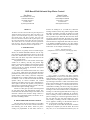
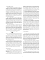
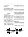
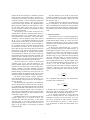
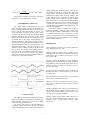
DSP-Based Field-Oriented Step Motor Control Dan Simon Dennis Feucht Cleveland State University 1960 East 24th Street Cleveland, OH 44115 216-687-5407 [email protected] Innovatia Laboratories 14554 Maplewood Road Townville, PA 16360 814-789-2100 [email protected] ABSTRACT ferred to as windings A (or 1) and B (or 2). When the windings conduct current, they produce magnetic fields that add to each other vectorially to produce an overall stator flux. The stator flux interacts with the rotor magnets to produce torque. When the stator and rotor fluxes are directly opposite each other, the motor is in a stable equilibrium and zero torque is produced. When the stator and rotor fluxes are aligned with each other, the motor is in an unstable equilibrium position. Any other relative orientation of the stator and rotor fluxes produces torque in the motor. As an example, consider Fig. 1. The SMC3 motor drive has been built using an Analog Devices ADSP-2101 digital signal processor (DSP). The SMC3 is designed to work with two-phase step motors, which are permanent magnet motors with many (typically 100) poles. The firmware in the SMC3 DSP drives the step motor phase windings using field-oriented control rather than using single steps. This method derives the maximum theoretical performance from the motor. This paper describes field-oriented control, and how the SMC3 hardware and firmware implements it. I. INTRODUCTION Figure 1: Step Motor Diagram (adapted from www.cs.uiowa.edu/~jones/step/types.html) Step motors, as typically driven in industrial applications, can exhibit undesirable behavior such as stepping resonances and skipped steps. However, this is due to the drive method that is used, and is not due to the motor itself. The name "step motor" indicates how the motor is typically driven. Step motors are low in cost because of their highvolume use in industry, and they also produce high torque at a given motor winding current (because of their many poles). This is desirable for low-speed position control, and also for reducing mechanical force-speed conversion such as gearing. The SMC3 uses field-oriented control (also called vector control), which derives the maximum theoretical performance from the motor. This approach is not widespread because, until recently, electronic components constrained drives to simple schemes such as stepping. In addition, it was not until the mid-1980s that the full dynamic theory of electric machines was worked out [Kr89]. The SMC3 does not need a tachometer because speed is derived from position, and position is derived from an incremental position encoder or directly from the motor's phase-winding voltages. Section II of this paper provides some background on step motor theory and field-oriented control. Section III discusses the hardware design of the SMC3, and Section IV discusses the firmware design. Section V presents some experimental results, and Section VI offers some concluding remarks. (a) Position 1 (b) Position 2 Fig. 1 portrays a two-phase step motor with the windings labeled "1" and "2". The rotor has six poles (in north-south pairs). In Fig. 1(a), current excites winding 1 such that the stator magnetic field leaves "north" at the top of the figure and enters "south" at the bottom of the figure. This will attract the rotor into the position shown. If the power to winding 1 is removed and current is commanded in winding 2 as shown in Fig. 1(b), then the rotor will move 30° (one step) clockwise. If the power to winding 2 is then removed and current is commanded in winding 1 in a direction opposite that shown in Fig. 1(a), then the rotor will rotate an additional 30° clockwise. Next, if winding 1 current is removed and current is applied to winding 2 in a direction opposite that shown in Fig. 1(b), then the rotor will rotate another 30° clockwise. Finally, if winding 2 current is removed and current is applied to winding 1 in the direction shown in Fig. 1(a), the motor will rotate yet another 30°. At this point we have taken the electrical excitation through one complete cycle, but the motor has moved only 120°, or 1/3 of a mechanical revolution (cycle). In II. FIELD-ORIENTED MOTOR CONTROL The step motors driven by the SMC3 are two-phase motors; they have two sets of wires wound on the stator (the stationary part of the motor). These two phasewindings are perpendicular to each other, and are re- 1 general, the relationship between electrical frequency and mechanical frequency is given by the equation other, then the resulting stator magnetic field vector will rotate at the sinusoidal frequency. fe = fm × P / 2 III. HARDWARE DESIGN where P is the number of rotor poles. The motors intended for the SMC3 are 100-pole motors, and so fe = 50 × fm. The stator magnetic field can be oriented in any direction by commanding the proper proportion of current in windings A and B. By maintaining the stator magnetic field vector 90° (electrical) ahead of the magnetic field vector of the rotor (in the direction of rotation), then the motor is field-orientated, and torque will be maximum (for a given power supply voltage). If winding A and B currents are sine-waves phased 90° with respect to each The following sections describe the various aspects of the SMC3 hardware. The SMC3 functional diagram is shown in Fig. 2 and a photograph of the SMC3 is shown in Fig. 3. The DSP program code is stored in a 27128 EPROM. At reset, the DSP boots in the program code and then proceeds to execute it. One reason for choosing the ADSP-2100 family of DSPs is that a 2-chip solution is possible because of the single EPROM bootstrapping (TI does not provide this feature). A 20 MHz crystal oscillator is mounted on the bottom side of the SMC3. Figure 2: SMC3 Hardware Functional Diagram User-Adjustable Pot 4-input MUX & 10-bit ADC DSP Configuration Jumpers Motor current sense amplifiers and analog processing Dual PWM Generator Encoder Interface Motor Voltage ZeroCrossing Detector 15V & 5V Control Supplies Converter External Bytewide Latch Stop Button Powerswitch translators and logic Dual power bridge driver From Motor Windings To Motor Windings Power Supply Figure 3: SMC3 Photograph Power driver supply A-phase H-bridge MOSFET gate A-phase H-bridge MOSFET power switches B-phase power driver Power-driver sense amplifiers and current-limit comparator Power connector: +12V, +5V, GND Switching power supply Dual PWM generator AD7811 ADC 27128 EPROM Stop and command inputs 74HC373 Latch External Input Port Incremental position encoder input 2 DSP reset IC ADSP-2101 DSP negative A output terminals. Heat sinks mounted on the MOSFETs (not shown in Fig. 3) are required for dissipation of MOSFET conduction and switching losses. The TO-220 MOSFET packages, shown in Fig. 3, have a 1.7 °C/W thermal resistance and can be operated with heat sinks at an output power of only a few watts. The Power Integrations INT-200 low-side and INT201 high-side MOSFET drivers work in pairs to prevent shoot-through (turning on both high and low-side MOSFETs at the same time). Both low and high-side drive waveforms are applied to the INT-200s. The PWM sign bit selects between the positive and negative low-side drivers, and also gates the PWM waveform to the highside drivers. The PWM signal is diode-ORed with a current-limiting signal (derived from the sense circuits described below in Section III C). This provides a fast, direct path for over-current turn-off. The gate drive to the MOSFETs must exceed the source voltage when on by at least 12 V. This is accomplished by charging bootstrap capacitors through diodes connected to the 15 V supply when the low-side drivers pull the output-side terminals of these capacitors to ground. Then the capacitors charge to 12 V (minus the diode drop). When the low-side switches are off and high-side on, the capacitors supply 12 V above the power supply to the INT-201s for gate drive to turn the high-side MOSFETs on. The series gate resistors are chosen to tailor the switching time to be as fast a possible without excessive voltage spikes in the circuit due to parasitic inductance. A. Dual PWM Generator The DSP generates two sinusoidal waveforms (for windings A and B) with frequencies and amplitudes computed by the DSP. The DSP firmware approximates the sine functions with the five-term, four-quadrant series expansion found in [Ma92]. The sine-waves are in PWM form, as signed PWM duty ratios. The sine-waves are applied to the motor windings through two full Hbridge power drivers (again, one for each winding). For smooth, steady-state motor operation, the two motor winding voltages must be sine-waves in quadrature. Each PWM on-time is represented by nine bits (one sign bit and eight magnitude bits). The 18 PWM bits are sent out serial port 1 (SPORT1) of the DSP, nine bits at a time. The PWM bits propagate through two 74HC595 shift registers. Meanwhile, a 74HC590 (8-bit counter) is driven at 10 MHz by a divide-by-two flip-flop (which is itself driven by the 20 MHz DSP clock). The eight LSBs of the shift registers comprise the winding A and B PWM duty-ratio magnitudes. The ninth bit is the sign bit. It switches the H-bridge for bipolar drive. The PWM magnitudes are compared with the counter output by two 74HC688 comparators. When the two inputs of a comparator are equal, the comparator output asserts low, which resets a flip-flop output that ends the PWM on-time and interrupts the DSP through IRQ2. Since the counter runs at 10 MHz, IRQ interrupts occur at a frequency of 10 MHz /256 = 39.0625 kHz. The PWM duty ratio is determined by the formula D= N +1 , N = 0, … ,254 256 C. Sense Circuits The output sense circuits measure motor winding voltages and currents. The winding voltage zero crossings are detected and input to the DSP as comparator output waveforms, and the currents are measured as scaled analog voltages (3.5 A/V). These voltages are input to an Analog Devices AD7811 ADC. The ADC outputs are sent to the serial port 0 (SPORT0) input of the DSP. The SPORT0 output simultaneously sets the channel for the next A/D sample acquisition. These measurements make it possible to implement many different firmware-level control schemes, including winding-sensed (sensorless) control. The DSP reads digitized motor winding voltages and currents from the motor and performs appropriate firmware-level signal processing. The DSP uses this feedback to compute the appropriate quantities (torque or speed), and then compares the acquired value to the commanded value. The error difference is processed by a firmware-level controller to achieve the desired dynamic loop response. The output quantities of the controller are the duty ratios, D, that are sent to the dual PWM generator via DSP SPORT1. To sense winding-voltage zero crossings, low-cost LM358 differential amplifiers low-pass filter the switching noise from the winding voltages before driving where N is the 8-bit magnitude that comes from the DSP. The end of a PWM cycle interrupts the DSP, which then computes new values of D for the A and B PWM signals. The composite 18-bit PWM data stream is shifted out of the DSP before the end of the PWM cycle, so that when it occurs, the updated values of D are loaded into the shift registers at the 255 count (reload state), starting the new cycle. For development and testing, it is hard to view a PWM waveform as a duty ratio changing in time. To recreate an approximate waveform, the PWM outputs are low-pass filtered with resistor-capacitor combinations and are available at test points on the SMC3. They normally appear as approximate (obviously sampled) sine magnitudes (haversines) that are in quadrature with each other. An example will be shown in Section V. B. Power Drivers The SMC3 contains two identical full H-bridge power drivers, one for each phase-winding. This section will consider only the winding A driver; the B driver is identical to it. The full H-bridge driver provides bipolar drive to the motor windings, connected between the positive and 3 The phase and speed estimator in Fig. 4 also estimates the rotational speed of the motor. A couple of options in the firmware provide speed estimates. One option is by differentiating the phase estimate. However, numerical differentiation is a difficult task because differentiation amplifies noise. Another option that has been implemented in the firmware for speed estimation is Kalman filtering. This gives a more accurate speed estimate, but if encoder data is available, numerical differentiation works well because of the high resolution of the encoder (4000 pulses per mechanical revolution). As we migrate the firmware towards winding-sensed control, the Kalman filter (or some type of phase-lock loop) will be used for speed estimation. The speed estimate is input by the speed controller to adjust PWM magnitude to achieve the desired motor speed. The winding currents that come from the ADC go into a current estimator for filtering. This part of the firmware has not yet been implemented, but generally a Kalman filter or phase-lock loop will be used to obtain a smooth current estimate. The sensed winding currents are quite noisy due to electrical switching noise, making current estimation a challenging problem [Si00]. The current estimate will then be input to the current controller, which will adjust the PWM outputs so that the commanded motor winding quantities are currents rather than voltages. This will make the sources driving motor windings appear as current sources rather than voltage sources, which will allow sensing of the motor induced voltages across the windings, to obtain their zero crossings. (If the sources across the motor windings appear as voltage sources, then the sensed winding voltages are merely the H-bridge voltage outputs and not the motor induced voltages.) LM393 zero-crossing comparators. The zero-crossing digital waveforms are inputs to the DSP. Similarly, another set of LM358 op-amps low-pass filter the winding currents before driving LM393 opamps which output to the ADC. D. External Data Bus Eight bits are available externally from a 74HC373 latch. The input byte is gated onto the DSP external bus for read cycles addressing data memory. These eight bits include three encoder bits (two quadrature bits and an absolute-position index bit), two phase-winding zerocrossing bits, a stop-command bit that can be asserted with a pushbutton, and two configuration jumpers. These eight bits are also available on a connector on the SMC3, as indicated in Fig. 3. The configuration jumpers can be used to select code segments in program boot memory. IV. DSP Firmware A. DSP Firmware Functions The DSP firmware functional diagram is shown in Fig. 4 and discussed in this section. First consider the inputs to the DSP. As seen in Fig. 4, the ADC inputs come into SPORT0. This data consists of sensed motor winding currents, as described above in Section III C, and a pot voltage that sets the commanded quantity. The other DSP input is the external data memory. This consists of encoder counts, and the zero crossings of the motor winding voltage, as described above in Section III D. The phase and speed estimator in Fig. 4 estimates the motor electrical phase which corresponds to the rotor position. The phase can be estimated using encoder counts, motor currents, zero crossings of the motor voltages, or any combination of these quantities. The present implementation of the SMC3 firmware includes only the encoder driver, although the hardware exists to sense motor currents and voltage zero-crossings. The phase output of the phase estimator inputs to the phase controller, which advances the commanded motor phase to keep it 90° ahead of the estimated phase, for field orientation. B. DSP Firmware Tasks The bulk of the work in the firmware is done in the 10 µs timer interrupt routine. This routine takes advantage of the ADSP-2101 secondary register set; registers do not have to be saved and restored at the beginning and end of the routine. This routine is where the latch data is read, and where the Encoder Driver and the Zero Crossing Driver (see Fig. 4) are called. The Phase & Speed Estimator, and the Phase Controller, are also Figure 4: Firmware Architecture ADC Inputs SPORT0 External Latch ADC Driver Encoder Driver Zero Crossing Driver Winding Currents Encoder Counts Phase & Speed Estimator Zero Crossings Current Estimator Current Controller Phase Controller PWM Generator Speed Controller 4 SPORT1 The RX0 interrupt occurs whenever ADC data is available on SPORT0. This routine extracts and formats the converted data, and essentially comprises the ADC Driver block in Fig. 4. The Main Routine of the firmware is an infinite loop that is interrupted by the interrupt routines discussed above. The Main Routine computes the sine of the phase that is output by the PWM Generator, performs magnitude limiting, and performs miscellaneous administrative tasks. called from the timer interrupt. For the Phase Controller block, the timer interrupt calls either an open-loop or a closed-loop control routine. (This option can be set with a firmware constant, or with a configuration jumper that is read from external memory.) The open-loop phasecontrol routine simply advances the commanded motor phase without any feedback of motor position or velocity. The motor phase advance rate can be set with a firmware constant, or with the user-adjustable pot setting that comes from the ADC. The closed-loop control routine advances the commanded phase on the basis of measured phase (however measured). Presently only encoder-based control has been implemented in the firmware. The encoder data is available as a two-bit quadrature signal with a value of 00, 01, 10, or 11. The difference between the previous and the present encoder data is used to derive the direction and rate of the motor rotation. We are presently using a 1000-line encoder, with 4000 encoder transitions per mechanical revolution. We can keep track of the motor speed as long as the encoder does not exceed two transitions per 10 µs interrupt. This translates to a maximum encoder sample rate of 200 kHz, which translates to 50 mechanical revolutions per second or 3000 rpm, the maximum rate the present controller can handle. The closed-loop phase controller simply advances the commanded phase in step with the encoder-derived motor phase to maintain the field orientation of the motor. The timer routine uses a counter to call the speed controller of Fig. 4 every 100 timer interrupts (a 1 ms period). Without speed control, the motor speed varies (especially at low speeds) due to motor bearing imperfections, asymmetry, and other anomalies. The speed controller uses optional encoder count differentiation or Kalman filtering to estimate the motor speed. The controller then adjusts the magnitude of the sine-wave from the phase controller to maintain a constant motor speed. The timer routine presently contains 120 instructions, which consumes (at 50 ns per instruction) 6 µs. We are therefore using about 60% of our throughput in the timer interrupt. The IRQ2 interrupt is generated by the PWM hardware (as discussed above in Section III A) at a frequency of 39.0625 kHz. The IRQ2 interrupt routine sends the PWM data out SPORT1 and initiates an A/D conversion. The firmware presently acquires only one channel of ADC data (a user-adjustable pot setting), but three additional channels include the two motor winding currents and the motor supply voltage. The IRQ2 interrupt occurs at 39.0625 kHz and must complete within 25.6 µs. It presently involves only 13 instructions, which takes less than 1 µs. The routine will grow longer as more ADC channels are used and ADC multiplexing logic is required, but there does not appear to be any danger of overrunning our allotted throughput budget. C. Frequency Synthesis The quadrature sine waves are generated digitally by the DSP firmware. Frequency is the rate of phase, dφ /dt. Assume that the phase variable, φ, is N bits. It is incremented by an amount ∆φ at a rate of fc times per second. The phase is then scaled appropriately and the sine of the phase is computed. In this case, the phase iteration rate, fc, is the frequency of the IRQ2 interrupt, or the PWM frequency of 39.0625 kHz. The phase of one cycle of a sine-wave (2π radians) is scaled to the word-length of the phase variable (N bits) so that when the variable exceeds its allowable range, it wraps continuously into the adjacent sine cycle. With this scaling, no end-of-cycle rollover calculation is required. Therefore, one bit of the N-bit phase variable represents 2π / 2N degrees of phase. In the case of the ADSP-2100 family, with a data word size of 16 bits, N = 16, and an LSB represents 2π / 216 = 96 µrad. The sine of the phase is therefore computed as sin(2πφ /2N), where φ is the N-bit value of the phase variable. The output frequency of the sinusoid is, in general, ∆φ f out = N f c 2 For a commanded output frequency, the required phaseincrement value is calculated as: f ∆φ = 2 N out fc 2N In the DSP code, fout is multiplied by 2 / fc. After multiplying, the upper N bits of the 2N-bit product are taken as the result, effectively dividing the product by 2N. As an example, assume that we want to drive the motor at a constant 1200 rpm. This corresponds to 20 mechanical revolutions per second, which, for a 100pole motor, corresponds to 1000 electrical revolutions per second. Therefore, we desire fout = 1 kHz. Given an fc of 39.0625 kHz, we obtain the desired phase increment of 5 voltage, thus causing the driving sources across the motor windings to function as current sources rather than voltage sources. This will then enable us to observe the induced motor voltage across the motor windings. This in turn will allow us to implement closed-loop phase control without encoders. However, in order to implement current control, we need an accurate estimate of the winding currents [Fe93]. These are available in the DSP from the ADC, but are noisy (see Fig. 5), necessitating a firmware filtering algorithm before completing the current control loop [Si00]. After current control is complete, we will be in a position to implement sensorless phase control. After sensorless phase control is implemented, we will be able to experiment with other types of control (e.g., torque control or speed control) using various interesting control technologies (fuzzy logic [Be00], H∞ control [Qi00], optimal control [Cr00], etc.) 1 kHz ∆ϕ = 216 = 1677 ≅ 10.7 bits 39.0625 kHz Since ∆φ has a resolution of ± 1/2 bit, fout has a resolution of 216 [(1/2) / 39.0625 kHz] = 0.30 Hz. V. EXPERIMENTAL RESULTS The SMC3 design has progressed to the point where closed-loop phase control (encoder-based) has been successfully implemented. Figure 5 shows an oscilloscope trace of some phase-winding A data for of a size 23 step-motor. The power converter supply voltage was about 7 V. The top trace is the commanded PWM duty-ratio magnitude; the second trace is the sensed winding current; the third trace is the PWM polarity; and the bottom trace is the sensed winding-voltage zero crossings. Though the motor induced voltage waveform zero-crossing cannot yet be obtained, the bottom trace is the present operation of the zero-crossing hardware. It is sensing the drive voltage, with zero-crossings in synchronism with the polarity reversals of the drive sinusoid. It can be seen that the sensed winding current is noisy and will have to be filtered in firmware in order to be used for current control. Likewise, the inducedvoltage zero crossings will need to be filtered because of the time jitter (noise) of the transitions. REFERENCES [An95] ADSP-2100 Family User's Manual (Third Edition), Analog Devices Inc., 1995. [Be00] F. Betin, D. Pinchon, and G. Capolino, "Fuzzy logic applied to speed control of a stepping motor drive," IEEE Transactions on Industrial Electronics, vol. 47, pp. 610-622, 2000. [Cr00] P. Crnosija, B. Kuzmanovic, and S. Ajdukovic, "Microcomputer implementation of optimal algorithms for closed-loop control of hybrid stepper motor drives," IEEE Transactions on Industrial Electronics, vol. 47, pp. 1319-1325, 2000. [Fe93] D. Feucht, "Sensorless Start-up Positioning of Brushless DC Motors," PCIM Magazine, vol. 19, pp. 2427, March 1993. [Kr89] P. Krause and O. Wasynczuk, Electromechanical Motion Devices, McGraw-Hill, 1989. [Ma92] A. Mar (ed.), Digital Signal Processing Applications Using the ADSP-2100 Family, Volume 1, Prentice Hall, 1992. [Qi00] G. Qingding and S. Yanna, "H∞ control based on internal model theory for linear permanent magnet synchronous servo motor (LPSM)," Control Theory & Applications, vol. 17, pp. 509-512, 2000. Figure 5: Oscilloscope Traces VI. CONCLUSION [Si00] D. Simon, "Design and rule base reduction of a fuzzy filter for the estimation of motor currents," International Journal of Approximate Reasoning, 2000, pp. 145-167. This paper has discussed the hardware and software design for the SMC3, a field-oriented, two-phase stepmotor controller. The hardware is based on an ADSP2100-family digital signal processor. Our present work focuses on the development of closed-loop current control. This will drive the PWM outputs to command a given current rather than a given 6


![ZXmore-V11-ConstructionKit [1144.78] KB](http://vs1.manualzilla.com/store/data/005859049_1-e30fafda14586d16f36a324828eeb8d9-150x150.png)