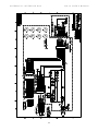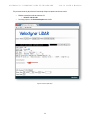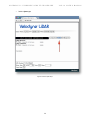
1
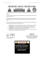
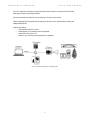
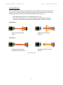
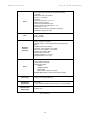
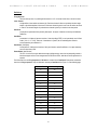
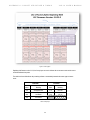
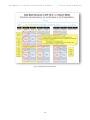
USER‘S MANUAL AND
PROGRAMMING GUIDE
VLP-16
Velodyne LiDAR Puck
TABLE OF CONTENTS
i SAFETY NOTICES
1 INTRODUCTION
2 PRINCIPLES OF OPERATION
3 Calibrated Reflectivities
4 Return Modes
7 SETUP
7 Case Contents
7 Mounting
8 Connections
8 Power
8 Ethernet
9 GPS
10 USAGE
10 Using the Sensor
12 SENSOR DATA
12 Data Packet Format
16 Time Stamp
16 Time Stamping Accuracy
16 Factory Bytes
17 The Position Packet
19 TROUBLESHOOTING
19 Service and Maintenance
20 SPECIFICATIONS
21 APPENDIX A
Packet Structure & Timing
29 APPENDIX B
Interface Box
34 APPENDIX C
Webserver GUI
35 APPENDIX D
Firmware Update Procedure
43 APPENDIX E
VeloView
44 APPENDIX F
Mechanical Drawing
VLP-16 USER’S MANUAL
SAFETY NOTICES
VLP-16 USER’S MANUAL
Caution
To reduce the risk of electric shock and to avoid violating the warranty, do not open sensor body. Refer servicing to
qualified service personnel.
The lightning flash with arrowhead symbol is intended to alert the user to the presence of uninsulated “dangerous
voltage” within the product’s enclosure that may be of sufficient magnitude to constitute a risk of electric shock to
persons.
The exclamation point symbol is intended to alert the user to the presence of important operating and maintenance
(servicing) instructions in the literature accompanying the product.
1.
2.
3.
4.
5.
Read Instructions – All safety and operating instructions should be read before the product is operated.
Retain Instructions – The safety and operating instructions should be retained for future reference.
Heed Warnings – All warnings on the product and in the operating instructions should be adhered to.
Follow Instructions – All operating and use instructions should be followed.
Servicing – The user should not attempt to service the product beyond what is described in the operating
instructions. All other servicing should be referred to Velodyne.
Complies with IEC 60825-1
CAUTION
Use of controls or
adjustments or performance
of procedures other than
those specified herein may
result in hazardous
radiation exposure
i INTRODUCTION
VLP-16 USER’S MANUAL
Congratulations on your purchase of a Velodyne VLP-16 Real-Time 3D LiDAR Sensor. This sensor provides state-ofthe-art 3D imaging in real time.
This manual describes how to set up and operate the VLP-16. It covers installation and wiring, output packet format
and interpretation, and GPS installation notes.
This manual is undergoing constant revision and improvement – check www.velodynelidar.com for updates.
1 PRINCIPLES OF OPERATION
VLP-16 USER’S MANUAL
The VLP-16 creates 360º 3D images by using 16 laser/detector pairs mounted in a compact housing. The housing
rapidly spins to scan the surrounding environment.
The lasers fire thousands of times per second, providing a rich, 3D point cloud in real time.
Advanced digital signal processing and waveform analysis provide high accuracy, extended distance sensing, and
calibrated reflectivity data.
Unique features include:
• Horizontal Field of View (FOV) of 360°
• Rotational speed of 5-20 rotations per second (adjustable)
• Vertical Field of View (FOV) of 30°
• Returns of up to 100 meters (useful range depends on application)
Figure 1. Overview of the LiDAR VLP-16 3D Imaging System
2 PRINCIPLES OF OPERATION
VLP-16 USER’S MANUAL
Calibrated Reflectivities
The VLP-16 measures the reflectivity of an object with 256-bit resolution independent of laser power and distance over
a range from 1m to 100m. Commercially available reflectivity standards and retro-reflectors are used for the absolute
calibration of the reflectivity, which is stored in a calibration table within the FPGA of the VLP-16.
•
•
Diffuse reflectors report values from 0-100 for reflectivities from 0% to 100%.
Retro-reflectors report values from 101 to 255 with 255 being the reported reflectivity for an ideal retroreflector and 101-254 being the reported reflectivity for partially obstructed or imperfect retro-reflectors.
Diffuse Reflector
Black, absorbent diffuse reflector
(value 0)
White, reflective diffuse reflector
(value 100)
Retro-Reflector:
Retro-reflector covered with semitransparent white surface (value 101)
Retro-reflector without any coverage
(value 255)
Figure 2. Reflector Types
3 PRINCIPLES OF OPERATION
VLP-16 USER’S MANUAL
Return Modes
Due to the laser’s beam divergence, a single laser firing often hits multiple objects producing multiple returns. The
VLP-16 analyzes multiple returns and reports either the strongest return, the last return, or both returns.
In the illustration below, the majority of the beam hits the near wall while the remainder of the beam hits the far wall.
The VLP-16 will record both returns only if the distance between the two objects is greater than 1m.
In the event that the strongest return is the last return, the second-strongest return is reported.
Figure 3. Return Modes
The dual return function is often used in forestry applications where the user needs to determine the height of the
trees. The figure below illustrates what happens when the laser spot hits the outer canopy, penetrates the leaves and
branches, and eventually hits the ground.
Figure 4a. Dual Returns Example 1
4 PRINCIPLES OF OPERATION
VLP-16 USER’S MANUAL
VeloView is able to display dual return data. Figure 4b below has two good examples of dual return data.
In this test area, the VLP-16 gets returns from the vinyl weather curtain (see inserted image) as well as from objects
inside the building.
Additionally, you can see where the beam is split on the edge of the loading dock. The blue lines indicate the portion of
the beam that hit the loading dock while the red lines indicate the portion of the beam that hit the ground beyond the
loading dock.
Figure 4b. Dual Returns Example 2
In dual return mode, the data rate of the sensor doubles. Data rates for the two modes are given below:
Mode
Packets/Second
Megabits/Second Strongest
754 ~ 8 Last
754 ~ 8 Dual
1508 ~ 16 Table 1. Dual Return Data Rates
5 PRINCIPLES OF OPERATION
VLP-16 USER’S MANUAL
The return mode is selected in the webserver user interface (Appendix C). In the screenshot below the Strongest
return is selected. The other options are Last and Dual.
Figure 5. Selecting Return Type
6 SETUP
VLP-16 USER’S MANUAL
This section describes the usual standard set up of the sensor assuming you are connecting the sensor to a standard
computer or laptop and mounting the sensor on a vehicle. For other connections and mounting locations, please
contact Velodyne for technical assistance.
A video showing the set-up of the VLP-16 in an office environment is available at:
https://www.youtube.com/watch?v=wUfHadExvs8
The standard setup involves:
1. Unpacking the shipping case contents.
2. Securely mounting the sensor to a vehicle or other scanning platform.
3. Connecting power to the sensor.
4. Connecting the sensor’s data output to the computer.
Case Contents
The shipping case contains:
• VLP-16 sensor unit with ~3 meter cable terminated at an interface box
• Desktop AC/DC power adapter (North American plug)
• 6’ AC cord
• Ethernet cable (1 meter)
• USB memory stick with:
o User manual (check www.velodynelidar.com for updates)
o Sample data sets and miscellaneous documents
o VeloView (free, open source viewing and recording software)
Mounting
The sensor base provides one ¼-20 threaded, 9/32” deep mounting hole and two precision locating holes for dowel
pins. The sensor can be mounted at any angle/orientation.
• The unit is weatherproofed to withstand wind, rain and other adverse weather conditions. Refer to the
specifications page for operational and storage temperature ranges.
• Be sure the unit is mounted securely to withstand vibration and shock without risk of detachment. The unit
does not need shock proofing. The unit is designed to withstand automotive G-forces; (500 m/sec2 amplitude,
11 msec duration shock and 3G rms 5 Hz to 2000 Hz vibration).
Figure 6. VLP-16 Base
7 SETUP
VLP-16 USER’S MANUAL
Connections
The VLP-16 comes with an integral cable that is terminated at an interface box. The cable is approximately 3 meters
(10’) in length and is permanently attached at the sensor, but it may be removed from the interface box for ease of
cable routing, direct wiring, and/or inserting in-line connector(s). The interface box provides connections for power,
Ethernet, and GPS inputs. For more information on the interface box, see Appendix B.
Power
The 2.1 mm barrel plug jack fits in the included AC/DC power adapter. The center pin is positive polarity.
Note: The VLP-16 does not have a power switch. It spins and operates approximately 5s after
power has been applied.
The VLP-16 requires 8 watts of power and is commonly used in vehicle applications where standard 12
volt, 2 amp power is readily available.
1.
2.
Connect the interface box.
Connect to the Ethernet port of any standard computer.
Note: Before operating the sensor, make sure that:
• The sensor is securely mounted
• Power is applied in the correct polarity
Ethernet
The standard RJ45 Ethernet connector connects to any standard computer.
IP Address: The IP address for each VLP-16 is set at the factory to 192.168.1.201, but can be
changed by the user via the WebServer GUI. For details on how to connect to the webserver GUI,
see Appendix C.
MAC address: Each VLP-16 has a unique MAC address that is defined by Velodyne and cannot
be changed.
Serial Number: Each VLP-16 has a unique serial number that is defined by Velodyne and cannot
be changed.
Note: The VLP-16 is only compatible with network cards that have either MDI or AUTO
MDIX capability.
8 SETUP
VLP-16 USER’S MANUAL
GPS
The VLP-16 can synchronize its data with precision, GPS-supplied time pulses enabling users to determine
the exact firing time of each laser.
External synchronization requires a user supplied GPS receiver generating a synchronization Pulse Per
Second (PPS) signal and a NMEA $GPRMC message (Appendix B). The $GPRMC message provides
minutes and seconds in Coordinated Universal Time. Upon synchronization, the sensor will read the minutes
and seconds from the $GPRMC message and use that to set the sensor’s time stamp to the number of
microseconds past the hour per UTC time. Synchronizing the VLP-16’s timestamps to UTC allows third party
software to easily geo-reference the LiDAR data into a point cloud.
GPS Receiver Option 1: User Supplied GPS Receiver
The user must configure their GPS device to issue a once-a-second synchronization pulse (PPS, 0-5V, rising
edge), typically output over a dedicated wire, and issue a once-a-second NMEA standard $GPRMC
sentence. No other output message from the GPS will be accepted by the VLP-16.
Note: The $GPRMC sentence can be configured for either hhmmss format or hhmmss.s format.
The GPS signals can be wired directly to the screw-terminal inside the interface box. If you wish to wire your
own GPS receiver, unscrew the top of the interface box and refer to the labeled screw terminal connector on
the circuit card (Appendix B).
GPS Receiver Option 2: Velodyne Supplied GPS Receiver
A consumer grade Garmin GPS receiver that is pre-programmed by Velodyne is available for purchase by
VLP-16 users. This receiver is pre-wired with a connector that plugs into the VLP-16 interface box, and it is
pre-programmed to output the correct $GPRMC sentence and PPS synchronization pulse. Contact Velodyne
for current pricing and order part number “92-GPS18LVC.”
Figure 7. Interface Box
9 USAGE
VLP-16 USER’S MANUAL
Using the Sensor
The VLP-16 sensor needs no configuration, calibration, or other setup to begin producing usable data. Once the unit is
mounted and wired, supplying power initiates scanning and the delivery of data. The quickest way to watch the VLP-16
in action is to use VeloView, the open-source viewer software (https://github.com/Kitware/VeloView) included with the
unit. VeloView reads the packets from the VLP-16 via the Ethernet connection, performs the necessary calculations to
determine point locations, then plots the points in 3D on the viewer’s computer. This is the recommended starting point
for new users. You can observe both distance and intensity data through VeloView. For more information on VeloView,
see Appendix E.
Most users will elect to create their own application-specific point cloud tracking and plotting and/or storage scheme.
There are several fundamental steps to this process:
1.
2.
3.
4.
Establish communication with the VLP-16
Parse the data packets for rotational angle, measured distance, and reported calibrated reflectivities
Calculate X, Y, Z coordinates from reported rotational angle, measured distance, and vertical angle
dependent on laser ID
Plot or store the data as needed
Each of these steps is described in detail below:
1.
Establish communication with the VLP-16.
The VLP-16 outputs two separate broadcast UDP packets. By using a network monitoring tool such as
Wireshark (https://www.wireshark.org/download.html) you can capture and observe the packets as they are
generated by the unit.
2.
Parse the data packets for rotational angle, measured distance, and reported calibrated reflectivities.
Your software needs to read the data packet from the Ethernet port, and extract the azimuth, elevation angle,
distance to the object, and time stamp. Once the data is identified, proceed to the next step. See Data
Packet Format in Appendix A.
3.
Calculate X, Y, Z coordinates from reported data.
The VLP-16 reports coordinates in spherical coordinates (r, ω, α). Consequently, a transformation is
necessary to convert to XYZ coordinates. The vertical/elevation angle (ω) is fixed and is given by the Laser
ID (Appendix A). The position of the return in the data packet indicates the Laser ID. The horizontal
angle/azimuth (α) is reported at the beginning of every other firing sequence, and the distance is reported in
the two distance bytes. With this information X, Y, Z coordinates can be calculated for each measured point.
Points with distances less than one meter should be ignored. The conversion is shown in Figure 8 on the
following page.
10 USAGE
VLP-16 USER’S MANUAL
Figure 8. Spherical to XYZ Conversion
4.
Plot or store the data as needed
The calculated X, Y, Z data is typically stored for later processing and/or it is displayed on a computer as a
series of point clouds.
Note: The VLP-16 has the capability to synchronize its data with GPS precision time via a Pulse
Per Second (PPS) signal from a GPS receiver. A synchronized timestamp from the VLP-16 sensor
may be used to match the data stream from the sensor with the data stream from the attached
external GPS receiver and/or Inertial Measurement Unit (IMU).
11 SENSOR DATA
VLP-16 USER’S MANUAL
Data Packet Format
The VLP-16 outputs two types of UDP Ethernet packets: Data Packets and Position Packets.
The Data Packet is comprised of the laser return values, calibrated reflectivity values, azimuth values, a time stamp,
and two factory bytes indicating the sensor model and the return mode (Strongest, Last, and Dual). The data packet is
1248 bytes long and is sent on port 2368.
Each VLP-16 data packet consists of a 42 byte header and a 1206 byte payload containing twelve blocks of 100-byte
data records. The data is followed by a four-byte time stamp data and two factory bytes. The data packet is then
combined with status and header data in a UDP packet and transmitted over the Ethernet.
The firing data is assembled into the packets in the firing order, with multi-byte values - azimuth, distance,
timestamp - transmitted least significant byte first.
The basic form of the data packet is shown below.
Figure 9a. Data Packet
Each data block begins with a two-byte start identifier “FF EE”, then a two-byte azimuth value (rotational angle),
followed by 32x 3-byte data records.
Azimuth Value
The reported azimuth is associated with the first laser shot in each collection of 16 laser shots. However, only
every other encoder angle is reported for alternate firing sequences. The user can choose to interpolate that
missing encoder stamp (see Appendix A).
12 SENSOR DATA
VLP-16 USER’S MANUAL
Valid values for the azimuth range from 0° to 359.99°
For example, in Figure 10a on page the following page, the second azimuth calculation for the second data
block would be:
1) Get Azimuth Values: 0x33 & 0x71
2) Reverse the bytes: 0x71 & 0x33
3) Combine the bytes into a two-byte, unsigned integer: 0x7133
4) Convert to decimal: 28,979
5) Divide by 100
6) Result: 289.79°
Hence value of the azimuth for the first laser firing the second data block is 289.79°
Note: The zero degree position on the sensor is directly opposite the cable connection (Appendix
F).
Data Record
Each three-byte data record consists of two distance bytes and a calibrated reflectivity byte.
Figure 9b. Data Record
The distance and reflectivity data are collected in the same staggered order in which the lasers are fired.
(see Appendix A). Distance to an object is reported in the first two of the three bytes in a data record. The
Calibrated Reflectivity value is reported in the third of the three bytes. The distance is reported to the nearest
2.0mm, meaning that the unsigned integer value given by the two distance bytes needs to be multiplied by
2.0mm to calculate the absolute distance to the object.
The Calibrated Reflectivity value is defined on a scale from 0-255. Refer to the Calibrated Reflectivities
section on page 3 for further details.
13 SENSOR DATA
VLP-16 USER’S MANUAL
Below is the first part of a sample packet as displayed in Wireshark.
Figure 10a. Sample Packet 1
14 SENSOR DATA
VLP-16 USER’S MANUAL
Below is the last part of a sample packet as displayed in Wireshark. Calculation of the timestamp and interpretation of
the Factory Bytes are shown.
Figure 10b. Sample Packet 2
For further information regarding the packet structure see Appendix A.
15 SENSOR DATA
VLP-16 USER’S MANUAL
Time Stamp
The four-byte time stamp is a 32-bit unsigned integer. This value represents microseconds from the top of the hour to
the first laser firing in the packet. The number ranges from 0 to 3600x106 µs (the number of microseconds in one
hour). The time stamp represents the time of the first shot of the first firing sequence. The time stamp, like the
reported distance, are transmitted least significant byte first.
All sixteen lasers are fired and recharged every 55.296µs. The cycle time between firings is 2.304µs. There are 16
firings (16 x 2.304µs) followed by a recharge period of 18.43µs. Therefore, the timing cycle to fire and recharge 16
lasers is given by ((16 x 2.304µs) + (1 x 18.43µs)) = 55.296µs
There are 24 of these 16-laser firing groups per packet, hence, it takes 1.33ms to accumulate one data packet. This
implies a data rate of 754 data packets/second (1/1.33ms).
The GPS timestamp feature is used to determine the exact firing time for each laser. This allows users to properly
time-align the VLP-16 data points with the pitch, roll, yaw, latitude, longitude, and altitude data from a GPS/Inertial
measurement system.
Time Stamping Accuracy
The following rules and subsequent accuracy apply for GPS time stamping.
1.
2.
When the VLP-16 powers up it runs on its own internal clock, and it begins issuing timestamps in
microseconds beginning from zero. Expect a drift of about 5 seconds per day under this method.
When a GPS is connected and synchronized, the NMEA $GPRMC sentence is reported in the position
packet as described in Appendix B. GPS time synching runs in one of two modes:
a.
b.
When the GPS achieves lock. The VLP-16 clock will then be within +/-50ps of the correct time at all
times. The timestamp reported will be in microseconds past the hour based on the current UTC
provided by the GPS.
Some GPS receivers have a battery back up and will continue to supply a time code for some
period (hours, days, or weeks). In this instance the accuracy is as good as the back up clock in the
GPS.
If the GPS is disconnected after synchronization the VLP-16 will continue to run its own clock and be subject to a drift
of approximately 5 seconds per day.
Factory Bytes
Every VLP-16 data packet, beginning with firmware version 3.0.23, identifies the type of sensor from which the packet
came and the return mode (Strongest, Last, Dual). The return mode determines how the packet should be interpreted.
See Figure 10b on the previous page.
Value
37h
38h
39h
Field 4DEh
Meaning
Strongest Return
Last Return
Dual Return
Field 4DFh
Value
Meaning
21h
HDL-32E
22h
VLP-16
Table 2. Factory Byte
16 SENSOR DATA
VLP-16 USER’S MANUAL
The Position Packet
The position packet is provided so the user can verify that the VLP-16 is receiving valid time updates from a GPS
receiver.
The position packet is a 554 byte long UDP packet broadcasted on port 8308. It consists of:
42 byte
Ethernet header
198 bytes
Unused
4 bytes
Timestamp
4 bytes
Unused
72 byte
NMEA $GPRMC sentence
234 bytes
Unused
Table 3. Position Packet
An example $GPRMC message is shown below:
$GPRMC,220516,A,5133.82,N,00042.24,W,173.8,231.8,130694,004.2,W*70
1
2
3
4
5
6
7
8
9
10 11 12
1
2
3
4
5
6
7
8
9
10
11
12
220516
A
5133.82
N
00042.24
W
173.8
231.8
130694
004.2
W
*70
Time Stamp
validity - A-ok, V-invalid
current Latitude
North/South
current Longitude
East/West
Speed in knots
True course
Date Stamp
Variation
East/West
checksum
The position packet returns the exact same $GPRMC message that was received from the GPS via the serial
connection.
Note: The Validity field in the $GPRMC message (‘A’ or ‘V’) should be checked by the user to ensure the
GPS system and the VLP-16 are receiving valid Coordinated Universal Time (UTC) updates from the user’s
GPS receiver.
Providing timestamps in UTC allows third party software to geo-reference the LiDAR data into a point cloud. Upon
synchronization, the sensor will read the minutes and seconds from the $GPRMC message and use that to set the
sensor’s time stamp to the number of microseconds past the hour per UTC time.
17 SENSOR DATA
VLP-16 USER’S MANUAL
Figure 11. Position Packet
18 TROUBLESHOOTING
VLP-16 USER’S MANUAL
Use this chart to troubleshoot common problems with the VLP-16.
Problem
Resolution
Unit doesn’t spin
Verify power connection and polarity.
Verify proper voltage — should be between 9 and 32
volts drawing a minimum of one amp.
Inspect the fuse in the interface module.
Replace if necessary (3 Amp automotive fuse).
Unit spins but no data
Verify Ethernet wiring.
Verify packet output using another application
(e.g. Ethereall/Wireshark).
Verify receiving computer’s network settings.
Set a static IP address in your computer’s network settings.
192.168.1.77
Verify that no security software has been installed which may block
Ethernet broadcasts.
Table 4. Troubleshooting
Service and Maintenance
There are no user serviceable nor maintenance requirements or procedures for the Velodyne VLP-16. Opening the
sensor will void the warranty.
For service or maintenance, please contact Velodyne at +1 (408) 465-2800, or log on to our website at
www.velodynelidar.com
19 SPECIFICATIONS
VLP-16 USER’S MANUAL
Sensor:
• Time of flight distance measurement with calibrated reflectivities
• 16 channels
• Measurement range up to 100 meters
• Accuracy +/- 3 cm (typical)
• Dual returns
• Field of view (vertical): 30° (+15° to -15°)
• Angular resolution (vertical): 2°
• Field of view (horizontal/azimuth): 360°
• Angular resolution (horizontal/azimuth): 0.1º - 0.4º
• Rotation rates: 5 - 20 Hz
• Integrated web server for easy monitoring and configuration
• Max altitude of operation 200 meters
Laser:
• Class 1 - eye safe
• 903 nm wavelength
Mechanical/
Electrical/
Operational:
Output:
Wave Length
Pulse Duration/
Repetition Rate
Maximum Power/
Energy Output
• Power consumption: 8 W (typical)
• Operating voltage: 9 - 32 VDC (with interface box and regulated power
supply)
• Weight: 830 grams (without cabling)
• Dimensions: 103 mm diameter x 72 mm height
• Shock: 500 m/sec2 amplitude, 11 msec duration
• Vibration: 5 Hz to 2000 Hz, 3G rms
• Environmental Protection: IP67
• Operating temperature -10° to + 60° C
• Storage temperature -40° to +105° C
• Up to 0.3 million points/second
• 100 Mbps Ethernet Connection
• UDP packets containing
- Distances
- Calibrated relectivities
- Rotation angles
- Synchronized time stamps (µs resolution)
• $GPRMC NMEA sentence from GPS receiver (GPS not included)
• 903 nm (min/max range is 896/910 nm)
• 6 ns (duration)
• 1.44µs * 16 lasers per pattern for a period of 46.1 µs = 21.7KHz (repetition)
•31 Watt (0.19 uJ)
Table 5. Specifications
20 APPENDIX A: PACKET STRUCTURE & TIMING
VLP-16 USER’S MANUAL
Definitions
Firing Sequence
The time and/or process of cycle-firing all the lasers in a VLP-16. It takes 55.296 uSec to fire all 16 Lasers.
Laser Channel
A single 905nm Laser emitter and detector pair. Each laser channel is fixed at a particular elevation angle
relative to the horizontal plane of the sensor. Each laser channel is given its own Laser ID number as shown
in Table 6. The elevation angle of a particular laser channel is given by its location in the data packet.
Data Point
A data point is represented in the packet by three bytes - two bytes of distance and one byte of Calibrated
Reflectivity.
Data Block
A data block is 100 bytes of data and consists of: A two-byte flag (xFFEE), a two-byte azimuth, and 32 Data
Points. [100 = 2 + 2 + 32*3]. There are 12 data blocks in a packet, but for calculating time offsets it’s
recommended they be numbered 0-11.
Data Packet (1248 Bytes)
A data packet is 1248 bytes and consists of 42 bytes of header, twelve Data Blocks, a four-byte timestamp,
and a two-byte factory field.
Return Modes (three choices)
The VLP-16 can be set to report either the strongest (by light energy) return, the last (temporally) default or
both the strongest and last. If the strongest return is also the last return, then the second-strongest return is
reported.
The information from two Firing Sequences of 16 lasers is contained in one Data Block. Each packet contains the
data from 24 firing sequences. Only one Azimuth is returned per Data Block. See Figure 12 on the following page.
Laser ID
Vertical Angle
0
-15°
1
1°
2
-13°
3
-3°
4
-11°
5
5°
6
-9°
7
7°
8
-7°
9
9°
10
-5°
11
11°
12
-3°
13
13°
14
-1°
15
15°
Table 6. Laser ID
21 APPENDIX A: PACKET STRUCTURE & TIMING
Figure 12. Data Block Structure (Single Return Mode)
22 VLP-16 USER’S MANUAL
APPENDIX A: PACKET STRUCTURE & TIMING
VLP-16 USER’S MANUAL
Figure 13. Factory Bytes
Beginning with firmware version 3.0.23, the factory bytes are used to indicate the current return mode and the sensor
model that delivered the packet.
The addition of these fields allows the processing software to automatically determine the sensor type and return
mode.
Field 4DEh
Field 4DFh
Value
Meaning
Value
Meaning
37h
Strongest Return
21h
HDL-32E
38h
Last Return
22h
VLP-16
39h
Dual Return
Table 2. Factory Byte
23 APPENDIX A: PACKET STRUCTURE & TIMING
Figure 14. Data Block Structure (Dual Return Mode)
24 VLP-16 USER’S MANUAL
APPENDIX A: PACKET STRUCTURE & TIMING
VLP-16 USER’S MANUAL
Azimuth Interpolation
Because the VLP-16 reports the azimuth value for every-other firing
sequence it’s helpful to interpolate the un-reported azimuth. There are
several ways to interpolate the un-reported azimuth, but the one given
below is simple and straight forward.
Consider a single data packet. The time between the first firing of the first
set of sixteen firings (Data Block 1) and the first firing of the third set of
sixteen laser firings (Data Block 2) is ~110.6µs. If you assume the
rotation speed over that short interval is constant, you can assume the
azimuth of the (N+1) set of sixteen laser firings is halfway between the
azimuth reported with the Nth set of 16 laser firings and the azimuth
reported with the (N+2) set of laser firings.
Below is pseudo-code that performs the interpolation. The code checks
to see if the azimuth rolled over from 359.99° to 0° between firing sets N
and N+2.
In the example below, N=1.
// First, adjust for a rollover from
359.99° to 0°
If (Azimuth[3] < Azimuth[1])
Then Azimuth[3]:= Azimuth[3]+360;
Figure 15. Azimuth Interpolation
Endif;
// Perform the interpolation
Azimuth[2]:=Azimuth[1]+((Azimuth[3]-Azimuth[1])/2);
// Correct for any rollover over from 359.99° to 0°
If (Azimuth[2]>360)
Then Azimuth[2]:= Azimuth[2]-360;
Endif 25 APPENDIX A: PACKET STRUCTURE & TIMING
VLP-16 USER’S MANUAL
Precise Data Point Timings
All sixteen lasers are fired and recharged every 55.296µs. The cycle time between firings is 2.304µs. There are 16
firings (16 x 2.304µs) followed by a recharge period of 18.43µs. Therefore, the timing cycle to fire and recharge all 16
lasers is given by ((16 x 2.304µs) + (1 x 18.43µs)) = 55.296µs.
To calculate the exact time in microseconds of each data point, first number the points in the firing sequence as
0-15. This becomes the data point index for your calculations. Next, number the firing sequences 0-23. This becomes
your sequence index.
Because the timestamp is the time of the first data point in the packet, you need to calculate a time offset for each data
point and then add that offset to the timestamp.
The offset equation is given by:
TimeOffset=(55.296µs * Sequence Index)+(2.304µs * Data Point Index)
To calculate the exact point time, add the TimeOffset to the timestamp.
ExactPointTime = Timestamp + TimeOffset
Example: Calculate the exact firing time of the last firing in a packet if the timestamp value is 45,231,878µs
Sequence Index = 23
Data Point Index = 15
Time Stamp = 45,231,878µs
ExactPointTime = Timestamp + TimeOffset
ExactPointTime = 45,231,878 + (55.296µs * 23) + (2.304µs * 15)
ExactPointTime = 45,231,878 + 1,306.368µs
ExactPointTime = 45,233,184.368µs
Additional examples are show in Figure 16, and a complete table of the offsets is given in Table 7.
26 APPENDIX A: PACKET STRUCTURE & TIMING
Figure 16. Time Offset Calculation
27 VLP-16 USER’S MANUAL
APPENDIX A: PACKET STRUCTURE & TIMING
Data Block
Laser ID
First
Firing
Second
Firing
VLP-16 USER’S MANUAL
0
1
2
3
4
5
6
7
8
9
10
11
0
0.00
110.59
221.18
331.78
442.37
552.96
663.55
774.14
884.74
995.33
1105.92
1216.51
1
2.30
112.90
223.49
334.08
444.67
555.26
665.86
776.45
887.04
997.63
1108.22
1218.82
2
4.61
115.20
225.79
336.38
446.98
557.57
668.16
778.75
889.34
999.94
1110.53
1221.12
3
6.91
117.50
228.10
338.69
449.28
559.87
670.46
781.06
891.65
1002.24
1112.83
1223.42
4
9.22
119.81
230.40
340.99
451.58
562.18
672.77
783.36
893.95
1004.54
1115.14
1225.73
5
11.52
122.11
232.70
343.30
453.89
564.48
675.07
785.66
896.26
1006.85
1117.44
1228.03
6
13.82
124.42
235.01
345.60
456.19
566.78
677.38
787.97
898.56
1009.15
1119.74
1230.34
7
16.13
126.72
237.31
347.90
458.50
569.09
679.68
790.27
900.86
1011.46
1122.05
1232.64
8
18.43
129.02
239.62
350.21
460.80
571.39
681.98
792.58
903.17
1013.76
1124.35
1234.94
9
20.74
131.33
241.92
352.51
463.10
573.70
684.29
794.88
905.47
1016.06
1126.66
1237.25
10
23.04
133.63
244.22
354.82
465.41
576.00
686.59
797.18
907.78
1018.37
1128.96
1239.55
11
25.34
135.94
246.53
357.12
467.71
578.30
688.90
799.49
910.08
1020.67
1131.26
1241.86
12
27.65
138.24
248.83
359.42
470.02
580.61
691.20
801.79
912.38
1022.98
1133.57
1244.16
13
29.95
140.54
251.14
361.73
472.32
582.91
693.50
804.10
914.69
1025.28
1135.87
1246.46
14
32.26
142.85
253.44
364.03
474.62
585.22
695.81
806.40
916.99
1027.58
1138.18
1248.77
15
34.56
145.15
255.74
366.34
476.93
587.52
698.11
808.70
919.30
1029.89
1140.48
1251.07
0
55.30
165.89
276.48
387.07
497.66
608.26
718.85
829.44
940.03
1050.62
1161.22
1271.81
1
57.60
168.19
278.78
389.38
499.97
610.56
721.15
831.74
942.34
1052.93
1163.52
1274.11
2
59.90
170.50
281.09
391.68
502.27
612.86
723.46
834.05
944.64
1055.23
1165.82
1276.42
3
62.21
172.80
283.39
393.98
504.58
615.17
725.76
836.35
946.94
1057.54
1168.13
1278.72
4
64.51
175.10
285.70
396.29
506.88
617.47
728.06
838.66
949.25
1059.84
1170.43
1281.02
5
66.82
177.41
288.00
398.59
509.18
619.78
730.37
840.96
951.55
1062.14
1172.74
1283.33
6
69.12
179.71
290.30
400.90
511.49
622.08
732.67
843.26
953.86
1064.45
1175.04
1285.63
7
71.42
182.02
292.61
403.20
513.79
624.38
734.98
845.57
956.16
1066.75
1177.34
1287.94
8
73.73
184.32
294.91
405.50
516.10
626.69
737.28
847.87
958.46
1069.06
1179.65
1290.24
9
76.03
186.62
297.22
407.81
518.40
628.99
739.58
850.18
960.77
1071.36
1181.95
1292.54
10
78.34
188.93
299.52
410.11
520.70
631.30
741.89
852.48
963.07
1073.66
1184.26
1294.85
11
80.64
191.23
301.82
412.42
523.01
633.60
744.19
854.78
965.38
1075.97
1186.56
1297.15
12
82.94
193.54
304.13
414.72
525.31
635.90
746.50
857.09
967.68
1078.27
1188.86
1299.46
13
85.25
195.84
306.43
417.02
527.62
638.21
748.80
859.39
969.98
1080.58
1191.17
1301.76
14
87.55
198.14
308.74
419.33
529.92
640.51
751.10
861.70
972.29
1082.88
1193.47
1304.06
15
89.86
200.45
311.04
421.63
532.22
642.82
753.41
864.00
974.59
1085.18
1195.78
1306.37
Table 7. Timing Offset Values
Note: All times in microseconds. Combine the value shown from the packet to arrive at actual laser firing time.
28 APPENDIX B: INTERFACE BOX
VLP-16 USER’S MANUAL
Using the Interface Box
Caution!
There is no internal polarity nor over voltage production in the sensors; therefore it is imperative that the Interface Box
and/or protective circuitry is incorporated in every installation.
The interface box contains circuitry to protect against:
1.
Over Voltage:
The Interface Box accepts 9-32VDC input voltage. The over voltage protection will kick in at 34V until the 3A
fuse blows.
2.
Reverse Voltage:
The reverse voltage protection kicks in at 0.6V until the 3A fuse blows or the TVS diode burns out.
Using the Sensors in Hardwired Applications
The sensors may be integrated into a custom system by removing the Interface Box and cutting the interface cable to
the desired length. When integrated into a custom system, adequate circuit protection – similar to that provided by the
interface box - must be included to safeguard against damaging the sensors.
Failing to provide adequate circuit protection may result in severe damage to the sensors.
Important!
When shortening the interface cable, take care to ensure the terminal block is correctly wired. Reversing the power and
ground at the terminal block may result in severe damage to the sensors.
29 APPENDIX B: INTERFACE BOX
VLP-16 USER’S MANUAL
Time Synchronization with an External GPS/INS System
The sensors can synchronize their data with precise GPS-supplied time. Synchronizing to the GPS pulse-per-second
(PPS) signal provides the ability to compute the exact firing time of each data point which aids in geo-referencing and
other applications.
To utilize these features the user must configure their GPS/INS device to issue a once-per-second synchronization
pulse in conjunction with a once-per-second NMEA $GPRMC sentence. No other NMEA message will be accepted by
the sensors. Other NMEA sentences might be misinterpreted by the sensors.
For additional information, please refer to the tables and diagrams in the following section “Interface Cable Signal
Description.”
• The serial data output from the GPS receiver should be connected to the sensor Interface Box via the screw
terminal labeled: “GPS RECEIVE.”
• The PPS output from the GPS/INS should be connected to the sensor Interface Box via the screw terminal
labeled: “GPS PULSE.”
• The ground signal(s) from the GPS/INS should be connected to the sensor Interface Box via the screw
terminal labeled: “GROUND.”
• Serial configuration for the NMEA Message should be 9600 baud, 8N1.
The PPS synchronization pulse and $GPRMC message may be issued concurrently or sequentially. The PPS
synchronization pulse length is not critical (typical lengths are between 20ms and 200ms), but reception of the
$GPRMC sentence must conclude less than 500ms after the rising edge of the synchronization pulse.
Figure 17. PPS Synchronization and $GPRMC Message
30 APPENDIX B: INTERFACE BOX
VLP-16 USER’S MANUAL
Interface Cable Signal Description
Wire
Signal
Input/Output
Specifications
Black
Ground
Input
System Ground
Red
Power
Input
9-15V DC / 12W
Yellow
GPS Sync Pulse
Input
TTL
White
GPS Serial Receive
Input
TTL
Light Orange
Ethernet TX+
Output
Differential
Orange
Ethernet TX-
Output
Differential
Light Blue
Ethernet RX+
Input
Differential
Blue
Ethernet RX-
Input
Differential
Table 8. Interface Cable Signal Description
Figure 18. Interface Box Connections
31 APPENDIX B: INTERFACE BOX
VLP-16 USER’S MANUAL
32 33 A
B
C
5
0
.790
8
SECTION G-G
SCALE 1 : 1
7
.437 THRU
.650 .023
4. MACHINE FEATURES SHOWN.
6
G
G
5
3. FINISH: PRINT WITH SUPPLIED ARTWORK (VELODYNE P/N 63-9082) - COLOR: PANTONE 877C
2. MATERIAL: MAKE FROM 58-756 POLYCASE LP-41BFMB1
1. ALL DIMENSIONS ARE IN DECIMAL INCHES.
.186
0
D
NOTES: UNLESS OTHERWISE SPECIFIED
THE WRITTEN PERMISSION OF VELODYNE ACOUSTICS, INC., IS PROHIBITED.
VELODYNE ACOUSTICS, INC., ANY REPRODUCTION IN PART OR WHOLE WITHOUT
6
4
4
F
F
NEXT ASSY
XX-XXX
ECN REV
REVISIONS
DESCRIPTION
2
SEE NOTES
SEE NOTES
3
DO NOT SCALE DRAWING
FINISH
MATERIAL
N/A
ANGLES
.xx .03 [0.76]
.xxx .005 [0.127]
DECIMALS
TOLERANCES ARE:
UNLESS OTHERWISE SPECIFIED
DIMENSIONS ARE IN DECIMAL
INCHES AND [METRIC].
ENG
QC
DATE
2
TAR 11/09/10
TAR 11/09/10
APPROVALS
DWN
CHKD
.180
0
1.050
.840
2.050
2.009
1.654
1.614
1.444
DATE
11/09/10
7/14/11
TAR
JLC
1
APPROVAL
B
SCALE= NTS
SIZE DWG. NO.
1
50-6001
A
SHEET 1 of 1
REV.
FAB ENCLOSURE,
ADAPTER,ABS,BLK,P2.0
Velodyne Acoustics, Inc.
SECTION F-F
SCALE 1 : 1
SOLIDWORKS2006
GENERATED DRAWING,
DO NOT MANUALLY UPDATE!
TYP R.030
3
E1 INITIAL ENGINEERING RELEASE
111863 A ADD 58-756 ENCLOSURE, LP-41 TO BOM;
RELEASE FOR PRODUCTION
3
GPS
POWER
ETHERNET
7
.020
0
8
0
.082
.196
.515
.602
.042
THE INFORMATION CONTAINED IN THIS DRAWING IS THE SOLE PROPERTY OF
A
B
C
D
APPENDIX B: INTERFACE BOX
VLP-16 USER’S MANUAL
APPENDIX C: WEBSERVER GUI
VLP-16 USER’S MANUAL
Setting up your computer to communicate with the sensor
•
•
•
•
•
•
•
Connect the computer to the interface box with an Ethernet Cable.
Apply power to the sensor.
For now, disable the WiFI connection on your computer.
Configure your computer’s IP address on its Ethernet port to manual mode.
Set your computer’s IP address to 192.168.1.77 (“77” can be any number except 0, 255, or 201)
Set the subnet mask to 255.255.255.0
Pull up the sensor’s webserver interface by typing the sensor’s network address, 192.168.201, into the
address bar in your web browser.
Note: Occasionally a computer won’t activate the new IP address unless the computer is rebooted. If you cannot
communicate with your sensor after double checking the IP address of the sensor (with Wireshark) and the IP address
of your computer, try rebooting the computer.
For detailed step-by-step instructions, follow the directions in the presentation found at this link:
http://velodyne.com/lidar/web/pdf/doc/Webserver%20Interface%20Instructions%20v1a.pdf
34 APPENDIX D: FIRMWARE UPDATE PROCEDURE
VLP-16 USER’S MANUAL
This procedure should only be performed if instructed by Velodyne to update a new firmware version.
•
•
Establish communication with the webserver GUI
o Default IP: 192.168.1.201
For backup purposes, click Download Snapshot and save file
Figure 19a. Firmware Update Step 1
35
APPENDIX D: FIRMWARE UPDATE PROCEDURE
•
Switch to System page
Figure 19b. Firmware Update Step 2
36
VLP-16 USER’S MANUAL
APPENDIX D: FIRMWARE UPDATE PROCEDURE
•
•
Click Choose File and locate firmware to be uploaded
Click Open and see file path in window
Figure 19c. Firmware Update Step 3
37
VLP-16 USER’S MANUAL
APPENDIX D: FIRMWARE UPDATE PROCEDURE
•
Click Update and notice progress status
Figure 19d. Firmware Update Step 4
38
VLP-16 USER’S MANUAL
APPENDIX D: FIRMWARE UPDATE PROCEDURE
•
•
•
Once uploaded the following window will open
Click Process Firmware Update
Monitor progress status
Figure 19e. Firmware Update Step 5
39
VLP-16 USER’S MANUAL
APPENDIX D: FIRMWARE UPDATE PROCEDURE
•
•
Once 100% has been reached, click Reset System
The main page will appear again after reset
Figure 19f. Firmware Update Step 6
40
VLP-16 USER’S MANUAL
APPENDIX D: FIRMWARE UPDATE PROCEDURE
•
Click Download Snapshot to save configuration after upload
Figure 19g. Firmware Update Step 7
41
VLP-16 USER’S MANUAL
APPENDIX D: FIRMWARE UPDATE PROCEDURE
•
Switch to Info screen to verify new firmware version
Figure 19h. Firmware Update Step 8
42
VLP-16 USER’S MANUAL
APPENDIX E: VeloView
VLP-16 USER’S MANUAL
VeloView performs real-time visualization of 3D LiDAR data from Velodyne sensors. VeloView can also playback prerecorded data stored in .pcap files. VeloView displays the distance measurements from the sensors as point cloud data
and supports customer color maps of multiple variables such as intensity-of-return, time, distance, azimuth, and laser
ID. The data can be exported as X, Y, Z data in CSV format or screenshots of the currently displayed point cloud can
be exported with the touch of a button.
Features
• Input from live sensor stream or recorded .pcap file
• Visualization of LiDAR returns in 3D + time including 3D position and attribute data such as timestamp,
azimuth, laser ID, etc.
• Spreadsheet inspector for LiDAR attributes
• Record to .pcap from sensor
• Export to CSV or VTK formats
• Record and export GPS and IMU data
• Ruler tool
• Visualize path of GPS data
• Show multiple frames of data simultaneously
• Show or hide subset of lasers
Installation
Download VeloView at the following link: http://www.paraview.org/Wiki/VeloView
Click on the executable file and follow the on screen instructions.
How to use
For “sensor streaming” (live display of sensor data) it is important to change the network settings of the Ethernet
adapter connected to the sensor to manual IP address selection and choose:
• IP address: 192.168.1.77 (77” can be any number except 0, 255, or 201)
• Gateway: 255.255.255.0
It is important to disable firewall restrictions for the Ethernet port. Disable the firewall completely for the Ethernet device
connected to the sensor or explicitly allow data from that Ethernet port (including both public and private networks).
43
44
A
B
C
D
8
7
6
8
3.50 88.9
.74 18.8
1.485 37.7
OPTICAL CENTER
2X
0°
7
.16 FEATURES
FOR 5/32 PINS
7/32 [5.5]
90°
6
NOTES:
1.
ALL DIMENSIONS ARE IN DECIMAL INCHES AND [MILLIMETERS].
2.
ALL DIMENSIONS FOR REFERENCE ONLY.
THE WRITTEN PERMISSION OF VELODYNE ACOUSTICS, INC., IS PROHIBITED.
VELODYNE ACOUSTICS, INC., ANY REPRODUCTION IN PART OR WHOLE WITHOUT
THE INFORMATION CONTAINED IN THIS DRAWING IS THE SOLE PROPERTY OF
5
.50 MAX 12.7 MAX
4
.50 MAX 12.7 MAX
.50 12.7
1/4-20 MOUNT
5/16 [7.9]
4
2.82 71.7
1.50 38.1
ACTIVE AREA
FULL 360°
4.07 103.3
5
NEXT ASSY
REV
SEE NOTES
SEE NOTES
3
DO NOT SCALE DRAWING
FINISH
MATERIAL
N/A
ANGLES
.xx .01 [0.25]
.xxx .005 [0.127]
DECIMALS
TOLERANCES ARE:
UNLESS OTHERWISE SPECIFIED
DIMENSIONS ARE IN DECIMAL
INCHES AND [METRIC].
ECN
3
DWN
ENG
QC
DATE
2
BRP 2014-12-05
APPROVALS
SOLIDWORKS
GENERATED DRAWING,
DO NOT MANUALLY UPDATE!
CHKD
REVISIONS
1
APPROVAL
DATE
B
SCALE= 1:1
SIZE DWG. NO.
86-0101
1
A
SHEET 1 of 2
REV.
VLP-16 ENVELOPE
Velodyne Acoustics, Inc.
DESCRIPTION
2
A
B
C
D
APPENDIX F: MECHANICAL DRAWING
VLP-16 USER’S MANUAL
45
A
B
C
D
8
7
8
DSR CHANNEL
15
13
11
9
7
5
3
1
14
12
10
8
6
4
2
0
7
THE WRITTEN PERMISSION OF VELODYNE ACOUSTICS, INC., IS PROHIBITED.
VELODYNE ACOUSTICS, INC., ANY REPRODUCTION IN PART OR WHOLE WITHOUT
THE INFORMATION CONTAINED IN THIS DRAWING IS THE SOLE PROPERTY OF
2.00° TYP
6
6
1.65
4
5
4
REV
CENTER AXIS
(MEASUREMENT ZERO)
ECN
3
3
APPROXIMATE BEAM CENTERS
DOES NOT REPRESENT BEAM WIDTHS
BEAMS ARE APPROXIMATELY .75 TALL AT FOCAL POINT
BEAM DIVERGENCE IS APPROXIMATELY 3 MILLIRADIANS
APPLY VERTICAL CORRECTION FOR GREATEST ACCURACY
5
REVISIONS
2
1
APPROVAL
SCALE= NTS
B
SIZE DWG. NO.
86-0101
1
.44 11.2
.38 9.7
.32 8.1
.26 6.6
.20 5.1
.14 3.7
.09 2.2
.03 0.7
0 (OPTICAL CENTER)
.03 0.7
.09 2.2
.14 3.7
.20 5.1
.26 6.6
.32 8.1
.38 9.7
.44 11.2
DESCRIPTION
2
A
SHEET 2 of 2
REV.
DATE
A
B
C
D
APPENDIX F: MECHANICAL DRAWING
VLP-16 USER’S MANUAL
Velodyne Acoustics, Inc.
345 Digital Drive
Morgan Hill CA 95037
408.465.2800 Voice
408.779.9227 Fax
408.779.9208 Service Fax
www.velodynelidar.com
Service Email: [email protected]
Sales Email: [email protected]
All Velodyne LiDAR products are made in the U.S.A.
Specifications subject to change without notice.
Other trademarks or registered trademarks are property of their
respective owner.
63-9243 Rev A Aug 2015