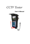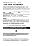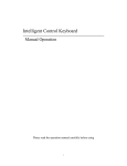
1
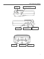
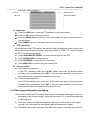
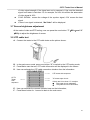
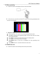
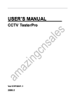
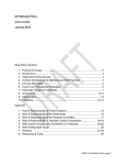
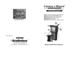
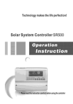
CCTV Tester User’s Manual Model: JW-T002 CCTV Tester User’s Manual Table of Contents 1, Safety Information..................................................................................................................2 1.1 Precaution before using the tester .................................................................................2 1.2 Precautions when using the tester .................................................................................2 1.3 Precautions for battery charging and using.................................................................2 2, Introduction .............................................................................................................................2 2.1 Features and function ........................................................................................................2 2.2 Standard items .....................................................................................................................3 2.3 Function of each part..........................................................................................................4 2.4 Specification .........................................................................................................................6 3, Operation Introduction .........................................................................................................7 3.1 Power and battery ...............................................................................................................7 3.2 Main menu introduction.....................................................................................................7 3.3 Video test...............................................................................................................................7 3.4 System information submenu.........................................................................................8 3.5 PTZ test ..................................................................................................................................8 3.6 Video signal attenuation analyzing.................................................................................9 3.7 Screen brightness adjustment.......................................................................................10 3.8 UTP cable test ....................................................................................................................10 3.7 Video generating................................................................................................................11 3.10 RS485 data test ................................................................................................................11 3.11 Digital multimeter ...........................................................................................................12 3.12 Output power to camera................................................................................................13 4, Warranty .................................................................................................................................14 4.1 Warranty items ...................................................................................................................14 4.2 Warranty exception ...........................................................................................................14 4.3 Complemented items........................................................................................................14 1 CCTV Tester User’s Manual 1, Safety Information 1.1 Precaution before using the tester A. Make sure to read the user’s manual before using the product. B. Make sure to check the input and output range of voltage or current at every input and output ports before connecting, so that the system cannot be overloaded. C. The following operational environment should be maintained constantly: l Temperature: 30℃ 70℃ l Relative humidity: 30% ~ 90% l Recharging voltage: DC5V 1.2 Precautions when using the tester A. Do not use the tester in damp humidity or leaking gas environments. B. Do not touch the tester with wet hands. C. Be mindful not to shock or shake the tester while in use to avoid damage. D. Avoid the places of strong magnetism or electric wave, which could cause incorrect measuring. E. Be careful not to expose the ports or joints to dirt or liquid. F. Do not disassemble the tester. 1.3 Precautions for battery charging and using A. Use only original chargeable battery with the tester, when charge the batteries, please use the original power adapter. B. Make sure not to disorient the polarization of batteries. C. Do not shortcircuit or disassemble batteries. 2, Introduction 2.1 Features and function A. Video test The video signal and the quality of picture can be tested. B. PTZ controlling It has the basic operational test of PTZ products, function include pan/tilt, zoom in/out, preset setting and operation, speed adjustment etc; support multiprotocol and baud rate, communication via RS232, RS422 simplex and RS485 port. RS485 protocol include: Pelco D,P, Samsung, Panasonic, Molynx. Additional Protocols may be added as per customer requests. 2 CCTV Tester User’s Manual Baud rate include: 2400, 4800, 9600, 19200. C. Power to camera The tester can output DC12V power to camera; it’s a helpful function when testing person can’t find power supply when they test a camera. D. Digital multimeter The tester can detect the AC/DC voltage and resistance, high testing range and precision can help installer find out the circuit problem. E. Video signal attenuation analyzing The tester can help installer to analyze the video signal attenuation by catching the video signal parameters. F. UTP cable test The wiring condition (disconnected, short of UTP cable) can be tested and show in the screen clearly. G. Video signal generating It can output Green, white Black and Blue screen to allow technician to inspect video monitor or DVR. The generating signal support PAL or NTSC (don’t support both meanwhile) format. H. RS485 data test It can test the RS485 data sent from controlling device, display the hexadecimal data content for engineer to analyze. 2.2 Standard items Item Quantity CCTV tester 1 Battery 1 Power adapter 1 UTP cable tester 1 BNC connect cable 1 Test lead set 1 Necklace 1 Multimeter cables 2 DC12V power cable 1 User manual 1 3 CCTV Tester User’s Manual 2.3 Function of each part Data Transmitting LED: Data Receiving LED: It lights when transmitting data. It lights when receiving data. Charge Indicating LED: Power LED: It is on when being charged. It is on when the tester is on. Glitters when charge finish. 2.5 inch LCD Screen: Open & setup: 960x240 resolution. Open iris & setup the functions Close & clear: Close Iris & clear the setup Menu: Long press back to main menu, Tele: display/hide submenu To zoom in the PTZ lens & send the generated video Shift setup buttons:: signal out to the display Shifts up, down, right, left for device. PTZ & menus & others. Wide: 09 numbuttons: To zoom out the PTZ lens & Input number when setup recalls the generated video preset, call preset & PTZ ID signal. Address: Far: Setup PTZ ID To adjust PTZ focus to far Set preset: Call preset: Near: In PTZ mode,press to start In PTZ mode,press to start To adjust PTZ focus to near to set preset to call preset 4 CCTV Tester User’s Manual RS232 port DC12V power output jack Power switcher Video input DC5V power jack RS422/485 port UTP cable jack Video output 5 CCTV Tester User’s Manual 2.4 Specification Model JW-T002 Signal Mode NTSC/PAL automatically suitable Display 2.5 inch LCD screen, 960 x 240 resolution Video Input 1 channel BNC Video Output 1 channel BNC Adjustable Brightness adjustable Communication RS232, RS422 simplex and RS485 Protocol Include more than 20 kinds of protocols or customized Baud Rate 2400,4800,9600,19200 DC Voltage Test Max: 1000V, Precision: 0.1mV AC Voltage Test Max: 750V, Precision: 0.1mV Resistance Test Max: 40MΩ, Precision: 0.1Ω Voltage DC12V Working Time 45 hours to normal camera Max Current 200mA Video analyzing Video signal attenuation analyzing UTP Cable Test Test UTP cable connection state Other Signal Generating Output 1 channel video signal for testing monitor Functions RS485 Data Test Test the RS485 data sent from controlling device OSD Menu English OSD menu Keyboard New design with number buttons, easy to operation Power Adapter DC5V Battery 3000mAh rechargeable battery inside Rechargeable 6 hours recharging time Low Consumption Sleeping mode, display battery power state Working Time 10 hours Work Temperature 30℃+70℃ Work Humidity 30%90% Dimension 166mm x91mm x48mm Weight 280g Video Test PTZ Control and Test Multimeter Function Power to Camera Power and Battery Others 6 CCTV Tester User’s Manual 3, Operation Introduction 3.1 Power and battery A. The power slide switch is located at the side of the tester. Turn the power slide switch on to power on the tester, turn it off to power off the tester; B. After the tester turning to sleeping mode, turn the slide switch on again to restart it; C. This tester has panel battery inside the device, more capacity, longer working time; D. Without the authorization from the manufacturer, please don’t release the rear panel and try to repair the battery; E. The batteries should be plugged in over 5 hours for full charge, when charged the Charge Indicating LED will on, after full charging, the Charge Indicating LED light will off and the charging work can stop automatically. F. The charged batteries can operate for 10 hours or more. G. When the battery indicator in system information menu shows 25 (the status number includes 100, 90, 75, 50, 25, 5), please recharge it for use. H. The tester can be used when it is being charged. 3.2 Main menu introduction Turn on the device; you will see the main menu, as the following shows: l 15 are five independent submenu; l Press the corresponding number button to get into the submenu; l Version number and S/N cant be edited; 1 SYSTEM SETUP ——> System information 2 PTZ CONTROLLING ——> PTZ controlling function 3 UTP TESTING 4 VIDEO GENERATING ——> UTP testing function 5 RS485 DATA ANALYZING ——> RS485 protocol analyzing 6 MULTI METER VER:V1.09 S/N:08110910 ——> Software version and S/N ——> Video generating function 3.3 Video test 7 CCTV Tester User’s Manual A. Connect the output terminal of video output system to the video input BNC of tester, turn on the tester, the video can be display on the screen. B. Connect the video output BNC of tester to the video input of other display device, it can display the video signal generated by the tester or looped by tester. 3.4 System information submenu A. Press “1” to switch to the system information submenu, as follows: PROTOCOL Pelco P ——> PTZ protocol COM 485 ——> Communication port in used RATE 4800 ——> Baudrate: 2400/4800/9600/19200 SPEED 016 ——> Pan and tilt speed IDLE TIME 000 ——> Idle time from last operation to auto turn off (minute) BATTERY 090 ——> Battery power status: 100/90/75/50/25/5 B. Press Set button to start the set up: C. Press numbutton ”2” and ”8” (PTZ direction button “UP” and “DOWN”) to select the option; (Battery power status can be edited) D. Press numbutton “2/6/8” (PTZ direction button “UP/DOWN/RIGHT”) to adjust the parameter; E. Press numbutton “4” (PTZ direction button “LEFT” )to save and quit; F. Press numbutton “4” again to finish the setup situation, the characters in the menu will stop glitter; G. Press MENU button for 1 second to back to the main menu. Note: In our device, PTZ there are 16 (some protocol ok has 7) levels for the PTZ, 0 means the minimum speed, 17 (or 7) means the maximum speed. 3.5 PTZ test A. Connection l Connect the tester with the PTZ camera as the picture shows. l In the main menu, press numbutton “2” to switch to the PTZ testing function 8 CCTV Tester User’s Manual submenu, as the following PTZ ID <—— ADDRESS:001 VIDEO:NULL ——> Video format 001255 PAL/NTSC/NULL B. Operation l Press the ADR button, input the PTZ address by using numbutton; l Press the SET button to save the setup; l Press the MENU button to hide the menu information and show a clean screen for camera image; l Press MENU button for 1 second to back to the main menu. C. PTZ controlling When connect to the PTZ correctly, the camera image will displayed in the screen of the tester, after setup the proper protocol, baud rate and the ID of the PTZ, user can control the PTZ as the following method: l Press UP/DOWN/LEFT/RIGHT to control the movement of the PTZ; l Press OPEN/CLOSE to control the iris; l Press FAR/NEAR to adjust the focus manually; l Press WIDE/TELE to zoom in/out the camera lens. D. Preset position l Set up the preset position In the PTZ controlling mode, press SPST button, then input the preset position number by the numbuttons, press SET to save the setup operation, user can use this method to set several preset positions one by one; l Calling the preset position In the PTZ controlling mode, press the CPST button, then input the preset position number by the numbuttons, press SET to save the setup operation, user can use this method to call several preset positions one by one; 3.6 Video signal attenuation analyzing At the mode of video and PTZ testing, when there is a analogue video signal connect in and display in the screen correctly, press the numbutton “1” to catch the parameter of video signal as: l MAX Vpp: means the difference between maximum and minimum of video signal strength, the video signal will be brighter when this parameter is bigger. l AVERAGE Vpp: means average of the difference between maximum and minimum 9 CCTV Tester User’s Manual of video signal strength, if the signal sent out by camera is 1Vpp, and the detected signal from tester is less than 1V, for example, its 0.8V, this means the attenuation of video signal is 20%. l SYNC SIGNAL:means the voltage of the synchro signal, 0.3V means the best signal. l If there is no signal is detected, “No Video” will be displayed. 3.7 Screen brightness adjustment At the mode of video and PTZ testing, user can press the numbutton “7”(BR+)and “9” (BR)to adjust the brightness of screen. 3.8 UTP cable test A. Connect the tester to the UTP cable tester as the picture shows: B. In the main menu mode, press numbutton “3” to switch to the UTP testing mode; C. Press Set to start the test, UTP cable information will be displayed in the screen. D. User can estimate the UTP cable connection situation from the information. UTP CABLE TEST 1 --- ----3 ——> UTP tester side sequence 2 --- ----6 3 --- ----1 CCTV 4 --- ----0 ——> ”0” means open circuit Tester <—— 5 --- ----0 ——> side If there are 2 line show “0”, it maybe: sequence 6 --- ----2 l They open circuit separately; 7 --- ----7 l They short circuit to each other; 8 --- ----8 E. User can estimate the connect situation base on the information; F. Press Menu button for 1 second to back to the main menu. 10 CCTV Tester User’s Manual 3.9 Video generating A. Connect the tester to the displayer device as the picture shows: B. In the main menu, press the numbutton”4” to switch to the video generating function submenu, as the follows: C. Operation setup l Press numbutton “4” to switch to the video generating function mode. l Press SET to switch the video generating signal: Color bar, Blue, Red, Pink, Green, Cyan, Yellow and White. l Press TELE to send the generated video signal to the display device. l Press WIDE to recall the generated video signal. l Press MENU button in short time to hid/display the video generating menu character. l Press MENU button for 1 second to back to the main menu. 3.10 RS485 data test A. Connect the tester to the controlling device as the picture shows: 11 CCTV Tester User’s Manual B. In the main menu, press numbutton “5” to switch to the RS485 protocol analyzing mode, as follows: DATA ANALYZING C. Press SET to start the setup of baud rate. D. Press UP/DOWN to select the tester’s baud rate, make it same with the controlling device’s. baud rate in using. E. Make the controlling device transfer the RS485 data to the tester, the hexadecimal signal data will displayed in the screen as follows, engineer can analyze the data to know if the controlling device work with the correct protocol. DATA ANALYZING A0 00 01 00 00 00 AF 0F A0 00 00 00 00 00 AF 0E A0 00 00 01 00 00 AF 0F A0 00 01 00 00 00 AF 4F A0 00 00 00 00 00 AF EF A0 00 00 00 00 00 AF 2F 3.11 Digital multimeter A. Connect the 2 detecting cable on the tester as the picture shows: 12 CCTV Tester User’s Manual B. Press the numbutton “6” to go to the multimeter submenu as follows: DC: 121.3mV 1 DC VOLTAGE 2 AC VOLTAGE 3 RESISTANCE C. Press the numbutton 1,2,3 can select the corresponding option: l DC voltage test range:01000V,precision:0.1mV; l AC voltage test range:750V,precision:0.1mV; l Resistance test range:040MΩ,precision:0.1Ω。 D. Press MENU button for 1 second to back to the main menu. Note:Please don’t test the voltage over the testing range, it can make the tester broken. 3.12 Output power to camera Connect the camera with the tester as the picture shows, connect the DC12V output from tester to the DC12V input port from the camera using the accessory “DC12V power cable”: 13 CCTV Tester User’s Manual The working time of camera are different because of different consumption camera, it can work more than 4 hours if it work with a camera that consumption current is less than 100mA, The maximum output current from tester is 200mA, please use the proper camera to work with. Note: 1. The output voltage of tester is DC12V, please make sure it work with the proper camera. 2. Please don’t connect the output to the input of tester itself, this can make the tester broken. 4, Warranty 4.1 Warranty items Since the delivery day: 1) Exchanging service within 15 days from the receiving day, we responsible for the freight charge (battery exchanging service within 90 days from the receiving day). 2) Repairing service within 1 year, change accessories and repair for free, customers should responsible for the freight charge (repairing service don’t include battery). 3) We provide whole life repairing service for our products with proper charge; customers should responsible for the freight charge. 4.2 Warranty exception We provide repairing service with proper charge, customers responsible for the freight charge 1) Damage caused by abuse, unreasonable use, mistreatment, or neglect. 2) Damage caused by modification or repair not authorized by our company, working in hostile environments, or natural disaster. 3) Damage caused by improper or improperly used packaging, or other devices work in the same system. 4.3 Complemented items 1) Company is not responsible for other assurance and other derivative from capital loss: The product and the user guides are not assured for particular users and some special purpose of use. 2) If the products returning for exchanging was damaged, modified or miss accessory, we will charge the proper payment. 3) If the components are no longer produced during the warrantylimited period, company will make a decision to replace similar products at no charge. 4) Don't offer exchanging service for special design products by customers. 14