1
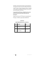
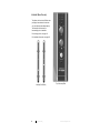
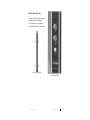
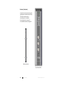
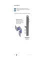
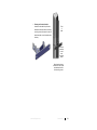
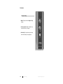
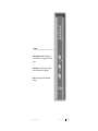
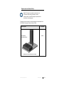
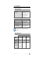
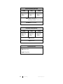
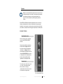
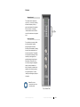
SAFESCAN® Ferromagnetic Detection Systems (FMDS) User Manual Intercept (Dual Pillars) Sentry (Single Pillar) Sentinel (Screener) ETS-Lindgren Inc. reserves the right to make changes to any product described herein in order to improve function, design, or for any other reason. Nothing contained herein shall constitute ETS-Lindgren Inc. assuming any liability whatsoever arising out of the application or use of any product or circuit described herein. ETS-Lindgren Inc. does not convey any license under its patent rights or the rights of others. © Copyright 2014–2015 by ETS-Lindgren Inc. All Rights Reserved. No part of this document may be copied by any means without written permission from ETS-Lindgren Inc. Trademarks used in this document: The ETS-Lindgren logo is a registered trademark of ETS-Lindgren Inc.; SAFESCAN is a registered trademark of MEDNOVUS INC. Revision Record MANUAL,FMDS SAFESCAN PILLARS | Part #399355, Rev. B ii Revision Description Date A Initial Release July, 2014 B Added Sentry and Sentinel product and CE information February, 2015 www.ets-lindgren.com Table of Contents Notes, Cautions, and Warnings ................................................ v 1.0 Introduction .......................................................................... 7 SAFESCAN FMDS Models ......................................................................... 7 Intercept (Dual Pillars) ........................................................................ 8 Sentry (Single Pillar) ........................................................................... 9 Sentinel (Screener) ........................................................................... 10 Features ................................................................................................... 11 Indicator Lights ................................................................................. 11 Audio Indicator .................................................................................. 11 Activation .......................................................................................... 11 Mounting Brackets ............................................................................ 12 Controls ............................................................................................ 14 ETS-Lindgren Product Information Bulletin ............................................... 16 2.0 Maintenance ....................................................................... 17 Verify Proper Operation ............................................................................ 17 Perform Indicator Test ...................................................................... 18 Perform Sensor Test ......................................................................... 18 Replacement and Optional Parts .............................................................. 19 Service Procedures .................................................................................. 20 Contacting ETS-Lindgren .................................................................. 20 Sending a Component for Service..................................................... 20 Calibration Services and Annual Calibration...................................... 20 3.0 Specifications ..................................................................... 21 Electrical Specifications ............................................................................ 21 Physical Specifications ............................................................................. 21 4.0 Installation .......................................................................... 23 Before You Begin Installation .................................................................... 23 Installation Location Requirements ................................................... 23 Electrical Requirements .................................................................... 24 Installing the Wall-Mounted Model ............................................................ 25 Intercept............................................................................................ 25 Sentry ............................................................................................... 26 Sentinel............................................................................................. 26 www.ets-lindgren.com iii Installing the Optional Free-Standing Model: Intercept, Sentry, Sentinel ... 27 Aligning: Intercept (Optional Free-Standing Model Only) ........................... 28 5.0 Controls and Indicators .................................................... 29 Sensors .................................................................................................... 29 Indicator Lights ......................................................................................... 30 Intercept / Sentry .............................................................................. 30 Sentinel............................................................................................. 30 Controls .................................................................................................... 31 Intercept / Sentry .............................................................................. 31 Sentinel............................................................................................. 33 6.0 Operation ............................................................................ 35 Pre-Screening Procedures ........................................................................ 35 Using the Intercept / Sentry....................................................................... 36 Using the Sentinel..................................................................................... 37 Appendix A: Warranty ............................................................. 39 Duration of Warranties .............................................................................. 39 Appendix B: EC Declaration of Conformity .......................... 41 iv www.ets-lindgren.com Notes, Cautions, and Warnings Note: Denotes helpful information intended to provide tips for better use of the product. Caution: Denotes a hazard. Failure to follow instructions could result in minor personal injury and/or property damage. Included text gives proper procedures. Warning: Denotes a hazard. Failure to follow instructions could result in SEVERE personal injury and/or property damage. Included text gives proper procedures. Note: See the ETS-Lindgren Product Information Bulletin for safety, regulatory, and other product marking information. www.ets-lindgren.com v This page intentionally left blank. vi www.ets-lindgren.com 1.0 Introduction Note: The SAFESCAN FMDS is intended to help deter significant ferromagnetic threats from entering the secured area. Ferromagnetic detection should be used as a second line of defense, and should not be used as a substitute for conscientious screening procedures. SAFESCAN FMDS Models The ETS-Lindgren SAFESCAN® Ferromagnetic Detection System (FMDS) provides three options for ferromagnetic detection: Intercept (Dual Pillars)—See page 8 for more information. Sentry (Single Pillar)—See page 9 for more information. Sentinel (Screener)—See page 10 for more information. www.ets-lindgren.com Introduction 7 INTERCEPT (DUAL PILLARS) Two pillars, side A and side B. Other than providing a beam reflector for the other one, each pillar operates independently. The Intercept is wall-mounted; a free-standing option is available. For mounting options, see page 12. For installation information, see page 23. Intercept (Dual Pillars) 8 Introduction Top of Intercept Pillar www.ets-lindgren.com SENTRY (SINGLE PILLAR) One pillar. The Sentry is wall-mounted; a free-standing option is available. For mounting options, see page 12. For installation information, see page 23. Sentry (Single Pillar) Top of Sentry Pillar www.ets-lindgren.com Introduction 9 SENTINEL (SCREENER) One pillar with continuous monitoring and a higher degree of sensitivity than the Sentry. The Sentinel is wall-mounted; a free-standing option is available. For mounting options, see page 12. For installation information, see page 23. Sentinel (Screener) Top of Sentinel Pillar 10 Introduction www.ets-lindgren.com Features Each pillar provides the following controls and indicators; for detailed information, see Controls and Indictors on page 29. INDICATOR LIGHTS The Intercept and the Sentry feature green and red indicator lights located in the top dome. The Sentinel features eight red LEDs located above the controls on the front panel. AUDIO INDICATOR The alarm buzzer for the Intercept and the Sentry is approximately 2.5 kHz to 3.8 kHz. The audio indicator for the Sentinel is a variable musical tone, increasing in pitch with increased ferromagnetic threat. ACTIVATION The Intercept features a photoelectric sensor with reflective beam. The Sentry features a one-sided beam with motion and object sensors. The Sentinel provides continuous monitoring. www.ets-lindgren.com Introduction 11 MOUNTING BRACKETS Note: As an alternative to hallway or doorway mounting, a free-standing optional base is available. For ordering information, see page 19. Each SAFESCAN model includes two sets of mounting brackets for each pillar: Hallway wall mount bracket— Attached to the back of the pillar with the including mounting screw, this bracket is used to attach the pillar to a wall located in a hallway. Front of pillar Bracket attaches to hallway wall Mount bracket shown installed on back of pillar and attached with mounting screw 12 Introduction www.ets-lindgren.com Doorway wall mount bracket— Installed on the side of the pillar and attached to the back with the including mounting screw, this bracket is used to attach the pillar to a wall located near a doorway. Front of pillar Bracket attaches to wall near doorway frame Mount bracket shown installed on side of pillar and attached to back with mounting screw www.ets-lindgren.com Introduction 13 CONTROLS Intercept / Sentry Mode—Rotary switch with Night and Day settings. Volume (speaker icon)—Variable rotary control from low (–) to high (+). Sensitivity—Four-position key lock rotary switch from lowest (1) to highest (4). Top of Intercept/Sentry Pillar 14 Introduction www.ets-lindgren.com Sentinel Volume (speaker icon)—Variable rotary control from low (–) to high (+) with audio off switch. Sensitivity—Four-position key lock rotary switch from lowest (1) to highest (4). Power—Rotary switch with Off and On settings. www.ets-lindgren.com Introduction 15 ETS-Lindgren Product Information Bulletin See the ETS-Lindgren Product Information Bulletin included with your shipment for the following: 16 Warranty information Safety, regulatory, and other product marking information Steps to receive your shipment Steps to return a component for service ETS-Lindgren calibration service ETS-Lindgren contact information Introduction www.ets-lindgren.com 2.0 Maintenance CAUTION: Before performing any maintenance, follow the safety information in the ETS-Lindgren Product Information Bulletin included with your shipment. WARNING: Maintenance of SAFESCAN FMDS is limited to external components such as cables or connectors. Clean the exterior of the cabinet using a damp cloth and mild cleaner. Always unplug the unit before cleaning. To prevent electrical shock, do not remove cover. WARRANTY Warranty may be void if the housing is opened. If you have any questions concerning maintenance, contact ETS-Lindgren Customer Service. Verify Proper Operation Note: Perform the following checks daily to verify proper operation. Use a small ferromagnetic test object (for example, a nail clipper) to trigger at various positions on each side and to verify proper alarm indication. For the Intercept and Sentry, block the infrared beam and then pass the nail clipper close to the vertical sensors from the bottom to the top in sequence. An alarm should be triggered in each instance. www.ets-lindgren.com Maintenance 17 PERFORM INDICATOR TEST Test the functions of each of these components: Top dome lights (Intercept/Sentry) Alarm light/LED indicators (Sentinel) Mode switch (Intercept/Sentry) Power switch (Sentinel) Reflective beam (Intercept) Audio buzzer/indicator Volume control PERFORM SENSOR TEST Test the functions of each of these components: 18 Sensor Analog circuits Digital signal processing Alarm logic Maintenance www.ets-lindgren.com Replacement and Optional Parts Note: ETS-Lindgren may substitute a similar part or new part number with the same functionality for another part/part number. Contact ETS-Lindgren for questions about part numbers and ordering parts. Following are the part numbers for ordering replacement or optional parts for the SAFESCAN® Ferromagnetic Detection System (FMDS). Part Description Base Assembly, Free-Standing Option Part Number 121824 Optional base shown with pillar (not included) www.ets-lindgren.com Maintenance 19 Service Procedures CONTACTING ETS-LINDGREN Note: Please see www.ets-lindgren.com for a list of ETS-Lindgren offices, including phone and email contact information. SENDING A COMPONENT FOR SERVICE For the steps to return a system or system component to ETS-Lindgren for service, see the Product Information Bulletin included with your shipment. CALIBRATION SERVICES AND ANNUAL CALIBRATION See the Product Information Bulletin included with your shipment for information on ETS-Lindgren calibration services. 20 Maintenance www.ets-lindgren.com 3.0 Specifications Electrical Specifications Audio Indicator: Intercept/Sentry: Alarm buzzer, approximately 2.5 kHz to 3.8 kHz Sentinel: Variable tone, pitch increases with increased ferromagnetic threat Power Input: 100–240 VAC, 50/60 Hz Power Consumption (per side): 6 Watts maximum, 3 Watts nominal Current Draw (per side): 110 VAC, 0.05A maximum, 0.03A nominal Note: Power is connected to each pillar from either the top or the bottom. Physical Specifications Intercept Sentry Sentinel Aperture: Variable, 26-in to 54-in Open Scan Area: 26-in to 54-in 24-in maximum 24-in maximum Weight (not including optional base): Each side: 16 kg (35 lb) 16 kg (35 lb) 16 kg (35 lb) www.ets-lindgren.com Open Total: 32 kg (70 lb) Specifications 21 Pillar Dimensions: Without Optional Base Intercept Sentry Height: 181.7 cm (71.55 in) Height: 181.7 cm (71.55 in) Sentinel Height: 194.4 cm (76.55 in) Width: Pillar only – 10.2 cm (4.0 in) With hallway mount bracket – 19.1 cm (7.5 in) Depth (Maximum): 16.2 cm (6.38 in) Pillar Dimensions: With Optional Base Intercept Height: 188 cm (74.09 in) Sentry Height: 188 cm (74.09 in) Sentinel Height: 200 cm (79.09 in) Width: 46 cm (18 in) Depth: 33 cm (13 in) Optional Base Dimensions Width: 33.02 cm (13.0 in) Length: 45.72 cm (18.0 in) 22 Specifications www.ets-lindgren.com 4.0 Installation CAUTION: Before connecting any components, follow the safety information in the ETS-Lindgren Product Information Bulletin included with your shipment. Before You Begin Installation Note: Each SAFESCAN model includes two sets of mounting brackets for each pillar for mounting either to a wall located in a hallway or to a wall located near a doorway. See Mounting Brackets on page 12 for more information. INSTALLATION LOCATION REQUIREMENTS Each SAFESCAN® Ferromagnetic Detection System (FMDS) model is wall-mounted; a free-standing option is available. Intercept The Intercept includes a left A side, a right B side, and two power adapters (one for each side). When installing the Intercept, space the dual pillars as follows: For entry/doorway protection: The recommended distance is 36 inches to 54 inches (or greater, when necessary). For more sensitive patient screening: The recommended distance is 26 inches to 33 inches. Each side of the free-standing model requires: A floor footprint of approximately 14-in by 13-in and a vertical clearance of 74 inches. The two sides can be separated by a variable aperture anywhere between 26 inches and 54 inches. www.ets-lindgren.com Installation 23 Sentry / Sentinel The Sentry and the Sentinel each include a single pillar and one power adapter. The installation location must meet these space requirements: The walk-past scanning aperture is 24 inches maximum. There must be 72 inches minimum free space around the pillar. The trigger beam senses both motion and objects, so the space must be clear of people, objects, and walls to ensure that the trigger beam functions properly. The optional free-standing model requires a floor footprint of approximately 14-in by 13-in and a vertical clearance of 74 inches for the Sentry or 79 inches for the Sentinel. The pillar must be positioned on one side of the area where the person or object to be checked will move past, within the 24-inch scan aperture and the 72 inches of free space. ELECTRICAL REQUIREMENTS The Sentry and the Sentinel each provide one power supply; the Intercept provides two power supplies, one for each pillar. The power supply includes a cord that plugs into a standard 110 VAC outlet (or 220 VAC, where applicable) and a +12 VDC output cable that connects to the pillar. Each pillar provides two +12 VDC input receptacles on each leg, one at the top and one at the bottom; either may be used. 24 Installation www.ets-lindgren.com Installing the Wall-Mounted Model Note: Each SAFESCAN model includes two sets of mounting brackets for each pillar for mounting either to a wall located in a hallway or to a wall located near a doorway. See Mounting Brackets on page 12 for more information, and then attach the desired bracket to the pillar. INTERCEPT Note: When mounting the pillars, make sure they are vertically aligned with each other, and that the front of each pillar is horizontally aligned with the other. If not in alignment, you will need to remove them and re-mount. 1. Select an appropriate installation location and position the two pillars. See Installation Location Requirements on page 23 for information. 2. Depending on the mounting bracket installed on the pillars, use toggle bolts (not included) to attach each bracket to the hallway walls or to the walls near the doorway. 3. Mount the power supplies either by the bottom of each pillar or in an overhead location. 4. Run the power cord from each power supply to a 110-VAC receptacle (or 220-VAC receptacle, where applicable). 5. Turn the Mode switch to the Night position on both pillars. 6. Connect the power supply output to each pillar. 7. Turn the Mode switch to the Day position on both pillars. 8. The top dome lights will illuminate green; scanning can then begin. 9. Test the pillars with a known ferromagnetic object to verify that the alarm is activated. www.ets-lindgren.com Installation 25 SENTRY 1. Select an appropriate installation location and position the single pillar. See Installation Location Requirements on page 23 for information. 2. Depending on the mounting bracket installed on the pillar, use toggle bolts (not included) to attach the bracket to the hallway wall or to the wall near the doorway. 3. Mount the power supply either by the bottom of the pillar or in an overhead location. 4. Run the power cord from the power supply to a 110-VAC receptacle (or 220-VAC receptacle, where applicable). 5. Turn the Mode switch to the Night position on the pillar. 6. Connect the power supply output to the pillar. 7. Turn the Mode switch to the Day position on the pillar. 8. The top dome lights will illuminate green; scanning can then begin. 9. Test the pillar with a known ferromagnetic object to verify that the alarm is activated. SENTINEL 26 1. Select an appropriate installation location and position the single pillar. See Installation Location Requirements on page 23 for information. 2. Depending on the mounting bracket installed on the pillar, use toggle bolts (not included) to attach the bracket to the hallway wall or to the wall near the doorway. 3. Mount the power supply either by the bottom of the pillar or in an overhead location. 4. Run the power cord from the power supply to a 110-VAC receptacle (or 220-VAC receptacle, where applicable). 5. Turn Power switch to the Off position. 6. Connect the power supply output to the pillar. 7. Turn Power switch to the On position. 8. Test the pillar with a known ferromagnetic object to verify that the alarm is activated. Installation www.ets-lindgren.com Installing the Optional Free-Standing Model: Intercept, Sentry, Sentinel Note: The optional free-standing model requires base assembly part# 121824. See page 19 for ordering information. 1. Attach the optional base to the pillar(s) per the instructions included with the base. Select an appropriate installation location; position the single pillar for the Sentry and the Sentinel and the two pillars for the Intercept. See Installation Location Requirements on page 23 for information. 2. Ensure that the feet are flush with the floor and not unbalanced. 3. Mount the single power supply for the Sentry and the Sentinel and the two power supplies for the Intercept. 4. Run the power cord from each power supply to a 110-VAC receptacle (or 220-VAC receptacle, where applicable). 5. Intercept only: Follow the steps on page 28 to align the pillars. Sentry only: Turn the Mode switch to the Night position on the pillar. Connect the power supply output to the pillar. Turn the Mode switch to the Day position on the pillar. Test the pillar with a known ferromagnetic object to verify that the alarm is activated. Sentinel only: Turn Power switch to the Off position. Connect the power supply output to the pillar. Turn Power switch to the On position. Test the pillar with a known ferromagnetic object to verify that the alarm is activated www.ets-lindgren.com Installation 27 Aligning: Intercept (Optional Free-Standing Model Only) Note: The two pillars must be aligned for proper functioning. This is accomplished when the infrared beam is aligned with the mirror system of the fellow pillar. 28 1. Disconnect the power from both pillars. 2. Turn the Mode switch to the Night position on both pillars. 3. Purposely misalign beams. 4. Connect the power on each pillar. 5. When the alarm buzzer stops, the pillars will be ready to align. 6. Rotate one pillar and find the center of the arc where red and green are both illuminated. Repeat for both pillars. 7. Turn the Mode switch to the Day position on both pillars. 8. Test the pillars with a known ferromagnetic object to verify that the alarm is activated. Installation www.ets-lindgren.com 5.0 Controls and Indicators CAUTION: Before placing into operation, follow the safety information in the ETS-Lindgren Product Information Bulletin included with your shipment. Note: The SAFESCAN FMDS is intended to help deter significant ferromagnetic threats from entering the secured area. Ferromagnetic detection should be used as a second line of defense, and should not be used as a substitute for conscientious screening procedures. In the MRI environment, a serious deterrent for ferromagnetic missile threats is the conscientious application of both diligent screening protocols and a quality ferromagnetic detection system. Detection depends upon a number of factors, including: Distance from the sensor Orientation of the threat to the sensor Shape of the threat (round, elongated, etc.) Presence or absence of pre-magnetization Characteristics of the material (ferromagnetically-hard versus ferromagnetically-soft) Sensors The SAFESCAN® Ferromagnetic Detection Systems (FMDS) has six sensors in each pillar (Intercept and Sentry models only). The sensors are located vertically at these approximate heights: head, shoulders, chest, waist, knee, and foot. www.ets-lindgren.com Controls and Indicators 29 Indicator Lights Warning: When an alarm is triggered, search diligently for the ferromagnetic threat(s). Note: An alarm trigger occurs independently on each of the two Intercept pillars. INTERCEPT / SENTRY Green Ready Lights—Three high-power green LEDs located inside the top dome on each of the pillars. These indicate the pillar is powered up and in the ready state. Red Alarm Lights—Three high-power red LEDs located inside the top dome on each of the pillars. The SAFESCAN FMDS will initiate ferromagnetic threat screening when the beam senses a passing person or object. When an alarm is triggered, the red lights will flash until the aperture is cleared. Additionally, when in the Night position, the top dome light will illuminate dim red. SENTINEL The Sentinel includes eight LEDs on the front panel, located above the controls. These LEDs illuminate red in four stages; the number of stages illuminated increases with increased ferromagnetic threat. A musical tone will also increase with increased ferromagnetic threat. 30 Controls and Indicators www.ets-lindgren.com Controls Note: It is recommended that the pillars be left on 24 hours a day if guarding the magnet room, except for turning them off momentarily at the beginning of each day to verify proper operation. See page 17 for more information on performing daily operational checks. Each SAFESCAN FMDS pillar operates independently with its own controls, indicators, internal electronics, sensors, reflective beam, and power supply. Additionally, for the Intercept, one pillar provides a beam reflector for the fellow pillar; however, each pillar senses and triggers independently of the fellow pillar. INTERCEPT / SENTRY Night/Day Mode Switch When connected to power, the lighting system of the SAFESCAN FMDS is activated. When leaving the facility at night, place the Mode switch in Night position and the Volume control at the highest level (clockwise). In the Night position, the top dome light will illuminate dim red; this indicates DO NOT ENTER. If a person or an object passes into the pillar aperture, the alarm will automatically activate regardless of a ferromagnetic threat. Volume Control The volume can be varied from very soft (—) to loud (+) by rotating the knob. After work hours, it is strongly recommended to set the Volume control full clockwise to the highest level. Top of Intercept/Sentry Pillar www.ets-lindgren.com Controls and Indicators 31 Sensitivity Switch Four positions are present, with 4, the right (clockwise) position, being the highest sensitivity. Sensitivity is decreased by rotating the switch counterclockwise to 1, the lowest sensitivity. This adjusts the threshold for alarming. Set the sensitivity to the highest level possible without having frequent false alarms. These can occur from close-moving ferromagnetic objects, such as hardware on doors. Sensitivity is related to the speed at which a person passes through the aperture. For best results, pass through as quickly as is feasible. Note: Do not use excessive force on the Sensitivity knob. The switch position can be locked in place by removing the key. 32 Controls and Indicators www.ets-lindgren.com SENTINEL Volume Control The volume can be varied from very soft (—) to loud (+). Rotating the knob completely to the (—) position will switch off the speaker. After work hours, it is strongly recommended to set the Volume control full clockwise to the highest level. Sensitivity Switch Four positions are present, with 4, the right (clockwise) position, being the highest sensitivity. Sensitivity is decreased by rotating the switch counterclockwise to 1, the lowest sensitivity. This adjusts the threshold for alarming. Set the sensitivity to the highest level possible without having frequent false alarms. These can occur from close-moving ferromagnetic objects, such as hardware on doors. Sensitivity is related to the speed at which a person passes through the aperture. For best results, pass through as quickly as is feasible. Note: Do not use excessive force on the Sensitivity knob. Top of Sentinel Pillar www.ets-lindgren.com Controls and Indicators 33 On/Off Switch When connected to power, the lighting system of the SAFESCAN FMDS is activated. When leaving the facility at night, place the Power switch in the On position and the Volume control at the highest level (clockwise). In the On position, after an automatic sound and light check, the two LEDs in the middle will illuminate red; this indicates DO NOT ENTER. If a person or an object enters the range of the pillar, the alarm will automatically activate regardless of a ferromagnetic threat. 34 Controls and Indicators www.ets-lindgren.com 6.0 Operation Warning: Use only AFTER the patient has undergone complete pre-screening and is cleared to enter the MRI magnet field. CAUTION: Before placing into operation, follow the safety information in the ETS-Lindgren Product Information Bulletin included with your shipment. Note: The SAFESCAN FMDS is intended to help deter significant ferromagnetic threats from entering the secured area. Ferromagnetic detection should be used as a second line of defense, and should not be used as a substitute for conscientious screening procedures. Pre-Screening Procedures Prior to entering the scan area for the Intercept, Sentry, or Sentinel, it is recommended that each person complete a thorough pre-screening process that includes, but is not limited to, a medical history and questionnaire. For example, the pre-screening should include questions regarding implanted medical devices, jewelry, hair pins, piercings, and pocket contents, to name a few. It is the responsibility of the customer to perform this type of pre-screening according to their internal procedures prior to a person entering the scan area for the Intercept, Sentry, or Sentinel. www.ets-lindgren.com Operation 35 Using the Intercept / Sentry Note: While smaller ferromagnetic threats can sometimes be detected, no pillar or portal can infallibly detect smaller threats, especially when these pass through the aperture close to the midline of the detector. Sensitivity is best when a threat object is closest to the sensors positioned within the vertical limbs. Because of the inverse cube law of physics, objects two times as close to the sensors elicit a signal 2 x 2 x 2 = 8 times stronger. 1. Perform pre-screening per internal procedures. 2. Stand just outside the scan area for the single pillar or the opening between the dual pillars (aperture). Confirm that the pillar is ready for operation by verifying that the top dome lights are illuminated green. Pass through the scan area or aperture. 3. 36 If a ferromagnetic object is detected, the green light(s) will turn off and an alarm will be initiated. The audio buzzer will sound and the top dome lights will flash red. The alarm will persist until the scan area is cleared, and then it will reset. Operation www.ets-lindgren.com Using the Sentinel Note: While smaller ferromagnetic threats can sometimes be detected, no pillar or portal can infallibly detect smaller threats, especially when these pass through the aperture close to the midline of the detector. Sensitivity is best when a threat object is closest to the sensors positioned within the vertical limbs. Because of the inverse cube law of physics, objects two times as close to the sensors elicit a signal 2 x 2 x 2 = 8 times stronger. 1. Perform pre-screening per internal procedures. 2. Stand just outside the scan area for the Sentinel. Confirm that the pillar is ready for operation by verifying the two LEDs in the middle are illuminated red. Walk to the Sentinel, face it, and do a 360-degree turn. 3. If a ferromagnetic object is detected, the eight red LEDs will flash in succession and the alarm will sound a variable musical tone that increases in pitch. The alarm will persist until the scan area is cleared, and then it will reset. www.ets-lindgren.com Operation 37 This page intentionally left blank. 38 Operation www.ets-lindgren.com Appendix A: Warranty Note: See the Product Information Bulletin included with your shipment for the complete ETS-Lindgren warranty. Duration of Warranties All product warranties, except the warranty of title, and all remedies for warranty failures are limited to one year. Product Warranted Duration of Warranty Period SAFESCAN Ferromagnetic Detection Systems (FMDS) 1 Year www.ets-lindgren.com Warranty 39 This page intentionally left blank. 40 Warranty www.ets-lindgren.com Appendix B: EC Declaration of Conformity 15 EC Declaration of Conformity We, ETS-Lindgren Inc., 1301 Arrow Point Drive, Cedar Park, Texas, 78613, USA, declare under our sole responsibility that the product: Product: SAFESCAN® Intercept SAFESCAN® Sentry Description: Ferromagnetic Detection System to which this declaration relates in conformity with the following European, harmonized and published standards at date of this declaration: Standard(s): ☒ CISPR 11:2003 – Industrial, scientific and medical (ISM) radio-frequency equipment – Electromagnetic disturbance characteristics – Limits and methods of measurement ☒ IEC 61000-3-2:2000 – Limits for harmonic current emissions (input current ≤ 16A per phase) ☒ IEC 61000-3-3:1994, A1:2001 – Limitation of voltage changes, voltage fluctuations and flicker in public low-voltage supply systems, for equipment with rated current ≤ 75A and subject to conditional connection ☒ IEC 61000-4-2:1995, A1:1998. A2:2000 – Electrostatic discharge immunity ☒ IEC 61000-4-3:2002 – Radiated, radio-frequency, electromagnetic field immunity test ☒ IEC 61000-4-4:2004 – Electrical fast transient/burst immunity test ☒ IEC 61000-4-5:1995, A1:2000 – Surge immunity test www.ets-lindgren.com EC Declaration of Conformity 41 ☒ IEC 61000-4-6:2003 – Immunity to conducted disturbances, induced by radio frequency fields ☐ IEC 61000-4-8:1993, A1:2000 – Power frequency magnetic field immunity test ☒ IEC 61000-4-11:2004 – Voltage dips, short interruptions and voltage variations immunity tests Directive(s): ☒ Low Voltage Directive (LVD): 73/23/EEC and its amending directives ☒ Electromagnetic Compatibility Directive (EMC): 89/336/EEC and its amending directives Authorized Signature: Jim Psencik Vice President, Engineering ETS-Lindgren Inc. 42 EC Declaration of Conformity www.ets-lindgren.com