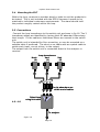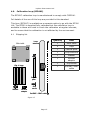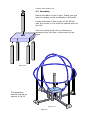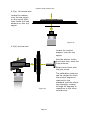
1
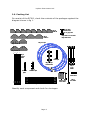
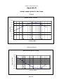
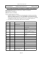
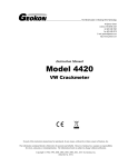
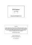
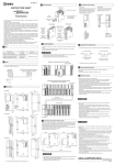
Laplace Instruments Ltd
LAPLACE INSTRUMENTS LTD
RF300
Large Loop Antenna
(Van Leen Loop)
2 metre diameter
Mk II-A
USER MANUAL
Ver 2.00
October 2011
Serial number:
Page 1
XXXX
Laplace Instruments Ltd
This Page intentionally blank
Page 2
Laplace Instruments Ltd
Index
1.0
2.0
3.0
4.0
5.0
6.0
Introduction
Packing List
Assembly
Calibration loop
Calibration
Operation
Appendix
A.
B.
Calibration data
Latest changes to standards
CISPR15 & CISPR16.
Page 3
Laplace Instruments Ltd
This Page intentionally blank
Page 4
Laplace Instruments Ltd
1.0
Introduction
The RF300 large loop antenna has been developed to meet the
requirements of EN55015: 2006 + A2: 2009, section 9.9.1, which
refers to CISPR16-1-4: 2007 + A1: 2008 section 4.6.1. This specifies
the limits for magnetic field induced current for luminaires with lamp
operating frequencies in excess of 100Hz.
Construction of the RF300 is as detailed in annex C of EN55016. This
antenna is fully compliant with the standard and details of the
calibration factors are included in this manual. These antenna factors
should be added to the results to obtain correct measurements that
can be compared directly with the limits.
Test setup and limits should be conducted as required by EN55015,
section 4.4.
The design of the RF300 is such that it can be readily erected and
provide a rigid and stable configuration for accurate and repeatable
measurements.
A calibration loop (RF300C) is available as an option if on-site
calibration is deemed necessary. The RF300C allows the calibration
loop to be used on all three axes and rotated within each as required
by the standards.
Page 5
Laplace Instruments Ltd
2.0 Packing List
On receipt of the RF300, check the contents of the packages against the
diagram shown in fig 1.
Qty 8
Plate D
Qty 31 Grip
Screws and
qty 31 grip nuts
Qty 8 M6 x 12 screws
Qty 8 M6 nuts
Qty 4
Plate C
Qty 3 loops
Qty 2 Plate B
Qty 2 Plate A
Qty 4
Corner
posts
Qty 2
tiewraps
Qty 3 Loop
transducers
Central
pillar
Qty 3
loop
leads
Qty 4
Saddle clips
10dB
attenuator
Switch unit
with cable
Qty 4 Base extensions
Identify each component and check for shortages.
Page 6
Qty 1
5m cable
Laplace Instruments Ltd
Quantity
Item
2
Plates A
2
Plates B
4
Plates C
8
Plates D
3
Loop antennas (Blue)
4
Corner posts
4
Base extensions
1
Central pillar
4
Saddle Clips
31
Grip screws
31
Grip nuts
(M10)
(M10)
8
M6 x 12 screws and nuts
3
Loop transducers (current sensors)
1
Switch Unit
1
Short BNC—BNC cable, patch cable
1
BNC—BNC cable (5m), output cable
3
BNC—BNC cable (1.5m), loop leads
1
10dB attenuator
2
Tiewraps
Page 7
Laplace Instruments Ltd
3.0 Assembly
3.1 Stage 1 Central sub-assembly
Establish a clear area with a level floor clear of metallic structures and
having a 3m clearance height.
Central pillar
1(a)….Secure Plates A to
the central pillar using the
supplied grip screws..
Note that the plates have
tapered holes to mach the
taper on the grip screws,
so ensure that these
plates are assembled
correct way round.
1(b)….Secure Plates B as
shown in fig 3.
Plates A
Figure 2
Plates B
Figure 3
1(c)…..Place the central post assembly in the
centre of the prepared area and add the 4 base
extensions, each using 2 grip screws.
Horizontal strut
Repeat in 4 places
Figure 4
Page 8
Laplace Instruments Ltd
3.2 Stage 2 Corner post assembly
Corner
post
2(a) ….Add plate C to the base of each corner
post using 2 grip screws. Repeat for the other
corner posts. Note that the plate is fitted on the
opposite side to the 2 mounting holes at the top
of the post.
2(b)…. Add the 2 Plates
D to each corner post
as shown. In Fig 6.
Plate C
Figure 5
Plates D
Figure 6
2(c.)…..Secure the corner posts to the
outer end of each base extension.
Join posts to
horizontal struts
Figure 7
Page 9
Laplace Instruments Ltd
3.3
Assembly of Loops
The frame should now look like that
shown in Figure 8.
The next steps are to add the loops.
Figure 8
3.3(a) The configuration of these loops is as shown in fig 9 and fig 10.
The connectors on each end of the loop are mated with the sockets either
side of each loop transducer. The retaining ring on each connector needs
to be screwed firmly to the socket but take care. These rings will bind
and be difficult to turn unless the loop is aligned properly. Force is not
necessary, simple jiggle the loop into alignment and the ring will turn
easily.
Figure 9
Page 10
Laplace Instruments Ltd
Screw loops connectors into
transducer sockets. Do not
force, adjust alignment to ease
tightening
BNC outlet for cable to selector
unit
Figure 10
3.3(b) Install the first loop on the stand. This is the horizontal
orientation. This task requires at least 2 persons.
The loop will simply rest in the slots at the top of the corner posts. Locate
the current transducer close to one of the corner posts. It will be found
that if the loop does not lie flat, by rotating it relative to the stand, and/
or inverting it, an optimum position can be found which results in the
‘flatest’ loop. Note that there is no requirement for a perfectly flat loop.
Some vertical displacement
round the loop will not affect
results.
Figure 11
Page 11
Laplace Instruments Ltd
Figure 12
3.3(c.) The second loop is
now fitted. Figs 12 and 13
show the details.
This loop is fitted inside the
first (horizontal) loop,
orientated so that it fits in
the lower ‘slot’ in the central
pillar and is held by the
saddle clips at the top of the
corner posts (fig 13).
Arrange the loop so that the
transducer is within 20 cm of
the central pillar.
Adjust the position of the
loop in the saddle clips to
give best circular shape of
the loop.
M6 x 12 screws
and M6 nuts
Figure 13
Page 12
Laplace Instruments Ltd
3.3 (d). The final loop is
now fitted INSIDE the other
two. See fig 14.
This fits in the upper slot in
the central pillar and under
the other vertical loop at
the top. Again arrange the
loop so the transducer is
close to the central pillar.
3.3(e). The loops can now
be adjusted for best shape
and position. Generally the
vertical loops will tend to
sag into the lower half of
Figure 14
the antenna. These are held
up in position by using the saddle clips on each corner post to take some
on the weight of the loop. The top of the vertical loops can be adjusted
for best shape and the two loops fastened together with the tiewraps as
shown in fig 15. With care, the tiewraps can be adjusted to produce
reasonable circles for each loop.
Note that the exact shape is not critical. Deviation from perfect circles is
inevitable but this has no significant effect on antenna performance.
EN55015 states in section 7.2 that
even the position of the UUT in the
antenna is not critical.
Figure 15
Arrangement at top of loops.
Use 2 tywraps in series for adequate
length.
Page 13
Laplace Instruments Ltd
3.4
Mounting the EUT
Within the loop, construct a wooden stand or table to suit the products to
be tested. This is not included with the RF300 because it needs to be
matched to individual customers requirements. The stand should hold
the product roughly central within the loop.
3.5 Connections
Connect the loop transducers to the switch unit as shown in fig 16. The 3
transducer cables are identified by having thick RF absorber filters along
their length. Fit the cables so that these filters are nearest to the switch
unit.
The switch unit is intended for floor mounting, or may be mounted on a
suitable table if preferred. The short co-ax cable acts as a patch cable to
switch each input, one at a time, to the output.
The output from the switch unit is connected direct to the analyser or
receiver.
Loop transducers
Vert
Vert
Horiz
(Z)
(Y)
(X)
Ferrite absorbers are
at this end of cables
Select loop
using link cable
4.0 4.0
To analyser
Figure 16
Page 14
Laplace Instruments Ltd
4.0
Calibration loop (RF300C)
The RF300C calibration loop is manufactured to comply with CISPR16.
Full details of the use of this loop are provided in this standard.
This item (RF300C) is available as a separate option to go with the RF300
LLA. The RF300 is supplied fully calibrated but the calibration loop is
available to those who wish to check the calibration at regular intervals,
and to ensure that the calibration is not affected by the environment.
4.1
Shipping list
Main table
Loop
antenna
Qty 4 Legs
Central
pillar
Washer
Vertical
adaptor
Grip
screw
5m BNC – BNC cable
Figure 17
Page 15
Quantity
Item
1
Main table
4
Legs
1
Central pillar
1
Loop antenna
1
Washer
1
Vertical
adaptor
1
Grip screw
1
5m BNC—BNC
calble
Laplace Instruments Ltd
4.2 Assembly
Mount the table on the 4 legs. These just slot
into the recess on the underside of the table.
Locate the table in the centre of the RF300,
with the centre in line with the central pillar of
the LLA.
Slot the central pillar of the calibratrion
assembly into the hole in the centre of the
table.
Figure 18
The assembly
should now be as
shown in fig 19
Figure 19
Page 16
Laplace Instruments Ltd
4.3(a) Horizontal axis
Locate the washer
over the top spigot
on the cenral pillar,
then locate the loop
antenna on this top
spigot.
Figure 20
4.3(b) Vertical axis
Locate the vertical
adaptor over the top
spigot.
Add the washer to the
horizontal stub, then the
loop antenna.
Retain both items with
the grip screw.
Figure 21
Page 17
The calibration antenna
can be rotated to check
the several angles as
required by the
standard, and the whole
top assembly rotated
through 90 degrees to
reposition to the other
vertical axis.
Laplace Instruments Ltd
5.0 Calibration
The calibration technique is fully described in CISPR16. It requires the
use of a signal generator covering the range 9KHz to 30MHz with a
50ohm output that is calibrated for 1v rms emf.
See appendix A
The calibration data for each loop is virtually identical. The following
details therefore apply to all three axes, although full data for each axis is
given in the appendix.
For reference, the ‘ideal’ curve is shown in graph 1. This is taken directly
from EN55016, annex C, Figure C8.
The antenna factor data for the RF300 are also given.
This ‘antenna factor’ correction data effectively converts the output from
the RF300 (measured in dBuV) directly to dBuA.
The data can be used with any analyser or receiver capable of EMC
measurements.
The estimated measurement uncertainty is 3dB.
For a detailed explanation of the calibration of the RF300 and discussion
of changes to CISPR15 (EN55015) and CISPR16, see appendix B
If using the SA1002 or SA3000 analyser:
The RF300 is listed under the normal Inputs menu. Just select this
device and the software automatically applies the appropriate correction
factors so that the trace reads correctly in dBuA and can be compared
directly with the EN55015 limits.
Further details are given in section 6.1
Page 18
Laplace Instruments Ltd
6.0 Operation
Details of the measurements and limits are given in EN55015, section
4.4. A copy of this should be consulted if performing compliance tests.
The UUT should be mounted on a wooden frame or table in the centre of
the antenna. The position is not critical.
Connecting cables to the EUT should leave the volume enclosed by the
loops in such a way as to be kept away from the loops to avoid capacitive
coupling. See Fig C6 in CISPR16.
Each axis (loop) should be measured in turn. Each should meet the
requirements of the standard. The loops are individually selected by
connecting the short patch lead to the appropriate input socket as shown
in fig 11.
6.1 Measurement with the SA1002 or SA3000 and EMCEngineer
Windows software.
1. Select the RF300 item under the input menu. The vertical scale will
indicate units of dBuA. (If this item is not available, you need a later
version of the software. Contact your supplier)
2 Under the limits menu, select the EN55015 ......... 2m loop antenna
limit line.
3. Connect the switch unit to the analyser input.
4. With the UUT switched off, check the background signal level. At
frequencies below 1MHz, the background can be very strong. If strong
signals do exist, check that the analyser is not in compression by
changing the input attenuator setting on the analyser and comparing
scans. Apart from the base line, the traces should overlay. If this
happens then it is OK to use the analyser with that attenuator setting. If
not, increase the attenuation and try again.
5. If the background is strong, it is advisable to either find a ‘quieter’
location or screen the room.
6. Switch the UUT on. Check the levels of signal over the background
levels using the techniques used for conventional radiated testing as
described in the user guide.
The levels displayed are fully compensated for the RF300 characteristics
Page 19
Laplace Instruments Ltd
and can be compared directly with the limit lines.
7. ALWAYS check for compression (overload) when taking
measurements. The amplitude of the reading on the screen cannot be
used directly as a guide for compression because the readings have been
adjusted for the RF300 characteristics.
If it is suspected that the signals are too strong even with the attenuator
switched in, install the 10dB attenuator in the input lead to the switch
unit. This additional attenuator can be automatically compensated for in
the software by adjusting the pre-amp settings on the screen.
10dB attenuator
Figure 22
8. If the background and the product is ‘quiet’, and especially at
frequencies above 20MHz, use 0dB attenuation.
Page 20
Laplace Instruments Ltd
APPENDIX A
CALIBRATION DATA
1.
CISPR16 ‘ideal’ plot
2.
Calibration data.
3.
RF300 actual sensitivity plots and RF300
correction plot (Antenna Factor)
Page 21
Laplace Instruments Ltd
This Page intentionally blank
Page 22
Laplace Instruments Ltd
EN55015 Standard antenna response
CISPR16 LLA (2m diameter)
60
65
Validation factor (dBohms)
70
75
80
85
90
95
100
105
110
0.01
0.1
1
Freq (MHz)
Page 23
10
100
Laplace Instruments Ltd
This Page intentionally blank
Page 24
Laplace Instruments Ltd
Calibration data
Freq.
MHz
0.01
0.04
0.10
0.50
1.00
2.51
5.04
10.01
12.00
15.09
20.09
25.03
30.00
Calibration
9108A
9108B
37.00
35.00
48.00
48.00
57.00
57.00
68.00
67.00
71.00
71.00
72.00
72.00
69.00
69.00
64.00
64.00
63.00
63.00
61.00
60.00
56.00
56.00
55.00
55.00
52.00
52.00
9108C
36.00
48.00
57.00
68.00
71.00
72.00
69.00
64.00
63.00
60.00
56.00
55.00
52.00
Freq.
MHz
0.01
0.04
0.10
0.50
1.00
2.51
5.04
10.01
12.00
15.09
20.09
25.03
30.00
Average
36.00
48.00
57.00
67.67
71.00
72.00
69.00
64.00
63.00
60.33
56.00
55.00
52.00
Max
37.00
48.00
57.00
68.00
71.00
72.00
69.00
64.00
63.00
61.00
56.00
55.00
52.00
Min
35.00
48.00
57.00
67.00
71.00
72.00
69.00
64.00
63.00
60.00
56.00
55.00
52.00
Range
2.00
0.00
0.00
1.00
0.00
0.00
0.00
0.00
0.00
1.00
0.00
0.00
0.00
Freq
0.01
0.04
0.10
0.50
1.00
2.51
5.04
10.01
12.00
15.09
20.09
25.03
30.00
EN
55015
46
46.5
46.5
46
45.5
44
41
37.5
37
36.5
36
35.5
35
Freq
0.01
0.04
0.10
0.50
1.00
2.51
5.04
10.01
12.00
15.09
20.09
25.03
30.00
Calibration sources
Laplace Instruments Ltd, RF300C calibration loop to CISPR16, annex C5.
Laplace Instruments Ltd, SA1002 Spectrum analyser s/n 1010
Calibration: Laplace: 16.03.2009
Marconi TF2016A signal generator, s/n 118032/004
Calibration: Checked against Marconi TF2019A, s/n 118449-169
Advantest R4131D calibrated by Schaffner, 20.11.02 and checked against
Marconi TF2019A, s/n 118449-169
Marconi TF2019A, serial number 118449-169, calibrated by Industrial
Calibration Ltd, 22.06.07
Page 25
A.F
10.00
-1.50
-10.50
-21.67
-25.50
-28.00
-28.00
-26.50
-26.00
-23.83
-20.00
-19.50
-17.00
Laplace Instruments Ltd
This Page intentionally blank
Page 26
Laplace Instruments Ltd
Appendix B
Actual output plots for the loops
Output
Output - RF300 s/n 9108
80.00
70.00
50.00
40.00
30.00
20.00
10.00
0.00
0.01
0.10
1.00
10.00
100.00
Frequency (MHz)
Antenna factor
Antenna factor RF300 s/n 9108
15.00
10.00
Antenna factor (dB)
Output (dBuV)
60.00
5.00
0.00
-5.00
-10.00
-15.00
-20.00
-25.00
-30.00
0.01
0.10
1.00
Frequency (MHz)
Page 27
10.00
100.00
Laplace Instruments Ltd
Page 28
Laplace Instruments Ltd
Appendix B
Changes to standards CISPR15 and CISPR16, 2009
Page 29
Laplace Instruments Ltd
Technical Report
Laplace Instruments Ltd
January 2010
RF300 Large loop antenna, an analysis of changes to the standards
These changes are due to the amendments to CISPR15 and CISPR16
The latest versions are now …..
CISPR15:2006 + A2:2009 and
CISPR16-1-4:2007 + A1:2008
The key changes related to LLAs are:
1. Sections related to the construction and specification of LLAs are moved from
CISPR15 to CISPR16. Note that in the new CISPR15, the requirements for the
LLA are referred to Section 4.7.1 in the new CISPR16, which does not exist! It
seems that the reference should be to Section 4.6.1. The same error is repeated
in CISPR16 which again refers in Annex C to the non-existent section 4.7.
2. The definition of the calibration data has been re-defined.
Previous New CISPR16
Notes
CISPR15
Annex B
Annex C
Description, construction and
validation of LAS
Annex C
Significant changes
Both annexes combined into one.
Clause B1
Clause C1
Introduction
Clause B2
Clause C2
Construction of LAS
Clause C3
Construction of loop
Clause B3
-----
Positioning of the LAS
Clause B4
Clause C4
Validation
Figure B1
Figure C1
General view
Loop antenna named LAS (Loop
Antenna System
Additional requirements for cables and
connectors.
Information previously included with
diagrams now included in text. Note low
R for inner conductor is required.
Requirement for minimum distance to
nearby objects,…… not included in new
CISPR16
New definition for validation factor. (see
below).
None
Figure B2
Figure C2
Position of slits
None
Figure C3
Construction of slits
None
Figure C5
Metal box for current probe
None
Figure B3
Figure C4
Example slit construction
None
Figure B4
Figure C8
Validation factor
Figure C7
Positions of calibration loop
Converted from dBuA to dB(Ω). See
below.
None
Figure C9
Construction of calibration loop None
Figure C1
Figure C11
Sensitivity vs diameter
Figure C2
Figure C10
Conversion factors between loop Factors for magnetic field with electric
current and magnetic field
field added. Factors for distance 30m
strength at a distance.
removed.
Page 30
None
Laplace Instruments Ltd
Note 1.
The details of the LLA were given in Annex B of CISPR15. These are now transferred
to Annex C of CISPR16. Most of the content has remained the same, but Table 1
summarises the changes.
Note 2
CISPR15 gave the verification data as a plot of loop current in dBuA vs frequency for
the standard test signal (1V, open circuit voltage with a source impedance of
50ohm). This seems to be a straightforward method, especially as the limits are
quoted in dBuA, so it’s a direct correlation between the calibration loop and the
limits.
CISPR16 is essentially the same information, but presented differently. It specifies
the relationship between the source voltage (1V, as specified above) and the output
current in the loop as measured by the current probe. Note that the current probe
has a transfer characteristic of 1V/A. The relationship between volts and current is
ohms, hence the use of dB(ohms) as the ‘validation factor’.
The result is therefore a conversion factor scaled in dB(Ω) to convert current to
voltage,
CISPR16 defines the validation factor dB(Ω) = 20*log(Vs/Ii) where Vs is the source
voltage and Ii is the loop current.
Vs = 1V = 1,000,000uV
Under ‘old’ CISPR15, for Ii @ 100KHz = 46dBuA = 200uA
So the new CISPR16 value is 20*log(1000000/200) = 74 dB(Ω)
and
Old CISPR15 for Ii @ 30MHz = 29dBuA = 29uA
So the new CISPR16 value is 20*log(1000000/29) = 91 dB(Ω)
These calculations confirm the relationship between the CISPR15 plot and the
CISPR16 validation factor.
The plots in the standards assume a current probe with a 1V/A transfer function.
Such probes are ‘active’ but provide a flat frequency response. The RF300 uses
passive probes which have a non-flat frequency response. This is not important if the
probe is ‘inside’ the calibration loop and has a linear transfer function with amplitude.
These factors hold true for the probe that is used. So the RF300 antenna uses an
antenna factor correction to produce a calibration that agrees with the validation
factor. This antenna factor is supplied with each antenna, and is equivalent to the
correction factors as supplied with all EMC antennas, test cells, LISNs and other types
of transducer.
Using the antenna factor data with the RF300 enables the output to be compared
directly with the limits as specified in EN55015.
Page 31
Laplace Instruments Ltd
LAPLACE INSTRUMENTS LTD
Tudor House
Grammar School Road
North Walsham
Norfolk
NR28 9JH
UK
Tel: +44 (0) 16 92 40 20 70
Fax: +44 (0) 16 92 40 49 10
Web: www.laplace.co.uk
E: [email protected]
Page 32