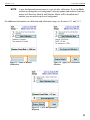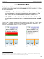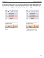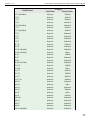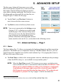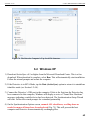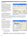
1
ORTEC
®
Micro-Detective
®
Detective -200
®
Portable Neutron and Gamma Nuclide Identifiers
User’s Manual
Software Version 3.1
Printed in U.S.A.
ORTEC Part No. 931046
Manual Revision G
0714
Advanced Measurement Technology, Inc.
a/k/a/ ORTEC®, a subsidiary of AMETEK®, Inc.
WARRANTY
ORTEC* warrants that the items will be delivered free from defects in material or workmanship. ORTEC makes no other
warranties, express or implied, and specifically NO WARRANTY OF MERCHANTABILITY OR FITNESS FOR A
PARTICULAR PURPOSE.
ORTEC’s exclusive liability is limited to repairing or replacing at ORTEC’s option, items found by ORTEC to be defective
in workmanship or materials within one year from the date of delivery. ORTEC’s liability on any claim of any kind, including
negligence, loss, or damages arising out of, connected with, or from the performance or breach thereof, or from the
manufacture, sale, delivery, resale, repair, or use of any item or services covered by this agreement or purchase order, shall in
no case exceed the price allocable to the item or service furnished or any part thereof that gives rise to the claim. In the event
ORTEC fails to manufacture or deliver items called for in this agreement or purchase order, ORTEC’s exclusive liability and
buyer’s exclusive remedy shall be release of the buyer from the obligation to pay the purchase price. In no event shall ORTEC
be liable for special or consequential damages.
Quality Control
Before being approved for shipment, each ORTEC instrument must pass a stringent set of quality control tests designed to
expose any flaws in materials or workmanship. Permanent records of these tests are maintained for use in warranty repair and
as a source of statistical information for design improvements.
Repair Service
If it becomes necessary to return this instrument for repair, it is essential that Customer Services be contacted in advance of
its return so that a Return Authorization Number can be assigned to the unit. Also, ORTEC must be informed, either in writing,
by telephone (865.482.4411) or by facsimile transmission (865.483.2133), of the nature of the fault of the instrument being
returned and of the model, serial, and revision (“Rev” on rear panel) numbers. Failure to do so may cause unnecessary delays
in getting the unit repaired. The ORTEC standard procedure requires that instruments returned for repair pass the same quality
control tests that are used for new-production instruments. Instruments that are returned should be packed so that they will
withstand normal transit handling and must be shipped PREPAID via Air Parcel Post or United Parcel Service to the designated
ORTEC repair center. The address label and the package should include the Return Authorization Number assigned.
Instruments being returned that are damaged in transit due to inadequate packing will be repaired at the sender’s expense, and
it will be the sender’s responsibility to make claim with the shipper. Instruments not in warranty should follow the same
procedure and ORTEC will provide a quotation.
Damage in Transit
Shipments should be examined immediately upon receipt for evidence of external or concealed damage. The carrier making
delivery should be notified immediately of any such damage, since the carrier is normally liable for damage in shipment.
Packing materials, waybills, and other such documentation should be preserved in order to establish claims. After such
notification to the carrier, please notify ORTEC of the circumstances so that assistance can be provided in making damage
claims and in providing replacement equipment, if necessary.
Copyright © 2014, Advanced Measurement Technology, Inc. All rights reserved.
*ORTEC® is a registered trademark of Advanced Measurement Technology, Inc. All other trademarks used herein are the property of their
respective owners.
NOTICE OF PROPRIETARY PROPERTY — This document and the information contained in it are the proprietary property of
AMETEK Inc., ORTEC Business Unit. It may not be copied or used in any manner nor may any of the information in or upon it be used for
any purpose without the express written consent of an authorized agent of AMETEK Inc., ORTEC Business Unit.
ADDITIONAL WARRANTY STATEMENT
Please note that the integrated computer that controls the Detective is
intended exclusively for the tasks detailed in this User’s Manual. Using
this computer for any other purpose could void your warranty.
In addition, the Detective contains no user-serviceable parts. Except for
the battery hatch on the left side panel, which can be opened when the
battery requires replacement, breaking the seal on the case voids your
warranty. The Detective should be opened only by ORTEC-authorized
service personnel.
If you have any questions about the use or maintenance of this instrument,
please contact your ORTEC representative or our Global Service Center
first.
IMPORTANT
The Detective is designed to function with the Regional Settings in
Microsoft® Windows® Mobile™ set to the English (United States) region
and all of its default settings, as discussed in Section 7.11. Using other
than the factory default settings can cause operational problems.
iii
[Intentionally blank]
iv
TABLE OF CONTENTS
WARRANTY . . . . . . . . . . . . . . . . . . . . . . . . . . . . . . . . . . . . . . . . . . . . . . . . . . . . . . . . . . . . . . . . ii
ADDITIONAL WARRANTY STATEMENT . . . . . . . . . . . . . . . . . . . . . . . . . . . . . . . . . . . . . . iii
Safety Instructions and Symbols . . . . . . . . . . . . . . . . . . . . . . . . . . . . . . . . . . . . . . . . . . . . . . . . . . ix
Cleaning Instructions . . . . . . . . . . . . . . . . . . . . . . . . . . . . . . . . . . . . . . . . . . . . . . . . . . . . . . . . . . . ix
1. INTRODUCTION . . . . . . . . . . . . . . . . . . . . . . . . . . . . . . . . . . . . . . . . . . . . . . . . . . . . . . . . . .
1.1. Monitoring Modes . . . . . . . . . . . . . . . . . . . . . . . . . . . . . . . . . . . . . . . . . . . . . . . . . . . . . .
1.2. Hardware Features . . . . . . . . . . . . . . . . . . . . . . . . . . . . . . . . . . . . . . . . . . . . . . . . . . . . . .
1.3. How This Manual Is Organized . . . . . . . . . . . . . . . . . . . . . . . . . . . . . . . . . . . . . . . . . . . .
1.4. Spectrum and Search File Storage, Transfer, and Viewing . . . . . . . . . . . . . . . . . . . . . .
1.4.1. Saving Spectra and Searches . . . . . . . . . . . . . . . . . . . . . . . . . . . . . . . . . . . . . . . .
1.4.2. File Formats and Filenaming Conventions . . . . . . . . . . . . . . . . . . . . . . . . . . . . .
1.4.2.1. Identification Mode Spectra . . . . . . . . . . . . . . . . . . . . . . . . . . . . . . . . .
1.4.2.2. Search Mode “Strip Charts” . . . . . . . . . . . . . . . . . . . . . . . . . . . . . . . . .
1.4.2.3. The Background File . . . . . . . . . . . . . . . . . . . . . . . . . . . . . . . . . . . . . . .
1.5. A Note About the Detective-200 User Interface . . . . . . . . . . . . . . . . . . . . . . . . . . . . . . .
1.6. The “Launcher” Interface for Multiple Identifier Applications . . . . . . . . . . . . . . . . . . .
1
1
3
4
5
6
6
6
7
7
7
7
2. GETTING STARTED . . . . . . . . . . . . . . . . . . . . . . . . . . . . . . . . . . . . . . . . . . . . . . . . . . . . . . . 9
2.1. Major System Components . . . . . . . . . . . . . . . . . . . . . . . . . . . . . . . . . . . . . . . . . . . . . . . 9
2.2. The Micro-Detective . . . . . . . . . . . . . . . . . . . . . . . . . . . . . . . . . . . . . . . . . . . . . . . . . . . . 9
2.2.1. Front Panel . . . . . . . . . . . . . . . . . . . . . . . . . . . . . . . . . . . . . . . . . . . . . . . . . . . . . . 9
2.2.2. Rear-Panel Connectors . . . . . . . . . . . . . . . . . . . . . . . . . . . . . . . . . . . . . . . . . . . . 10
2.2.3. The Internal Battery . . . . . . . . . . . . . . . . . . . . . . . . . . . . . . . . . . . . . . . . . . . . . . 10
2.2.4. The Touchscreen . . . . . . . . . . . . . . . . . . . . . . . . . . . . . . . . . . . . . . . . . . . . . . . . 11
2.2.5. Attaching the Carrying Strap . . . . . . . . . . . . . . . . . . . . . . . . . . . . . . . . . . . . . . . 11
2.3. The Detective-200 . . . . . . . . . . . . . . . . . . . . . . . . . . . . . . . . . . . . . . . . . . . . . . . . . . . . . 12
2.4. Internal vs. External Power . . . . . . . . . . . . . . . . . . . . . . . . . . . . . . . . . . . . . . . . . . . . . . 13
2.5. Operating Cautions and Notes . . . . . . . . . . . . . . . . . . . . . . . . . . . . . . . . . . . . . . . . . . . . 13
2.6. Startup and Cooldown . . . . . . . . . . . . . . . . . . . . . . . . . . . . . . . . . . . . . . . . . . . . . . . . . . 15
2.6.1. Connecting the Detective to External Power and Turning It On . . . . . . . . . . . . 15
2.6.2. Turning On the Mechanical Cooler . . . . . . . . . . . . . . . . . . . . . . . . . . . . . . . . . . 16
2.7. The User Interface . . . . . . . . . . . . . . . . . . . . . . . . . . . . . . . . . . . . . . . . . . . . . . . . . . . . . 17
2.7.1. Instrument Status Indicators . . . . . . . . . . . . . . . . . . . . . . . . . . . . . . . . . . . . . . . . 17
2.7.2. Moving Through the Menus . . . . . . . . . . . . . . . . . . . . . . . . . . . . . . . . . . . . . . . . 17
2.8. Customizing the Detective Settings . . . . . . . . . . . . . . . . . . . . . . . . . . . . . . . . . . . . . . . . 18
2.9. Checking the Calibration . . . . . . . . . . . . . . . . . . . . . . . . . . . . . . . . . . . . . . . . . . . . . . . . 19
v
Micro-Detective® and Detective®-200 Portable Nuclide Identifiers — User’s Manual
931046G / 0714
2.10. Running A New Background After Calibration . . . . . . . . . . . . . . . . . . . . . . . . . . . . . 22
3. RADIATION MONITORING . . . . . . . . . . . . . . . . . . . . . . . . . . . . . . . . . . . . . . . . . . . . . . . .
3.1. Survey (Count-Rate/Dose-Rate) Mode . . . . . . . . . . . . . . . . . . . . . . . . . . . . . . . . . . . . .
3.2. Identification Mode . . . . . . . . . . . . . . . . . . . . . . . . . . . . . . . . . . . . . . . . . . . . . . . . . . . .
3.2.1. Start the Identification . . . . . . . . . . . . . . . . . . . . . . . . . . . . . . . . . . . . . . . . . . . .
3.2.2. Extending the Count-to-Preset . . . . . . . . . . . . . . . . . . . . . . . . . . . . . . . . . . . . . .
3.2.3. Save . . . . . . . . . . . . . . . . . . . . . . . . . . . . . . . . . . . . . . . . . . . . . . . . . . . . . . . . . . .
3.2.4. View Found Nuclides List for Classify ID Display Mode . . . . . . . . . . . . . . . .
3.2.5. Intense (View Highest-Intensity Spectrum Lines) . . . . . . . . . . . . . . . . . . . . . . .
3.2.6. Display Spectrum . . . . . . . . . . . . . . . . . . . . . . . . . . . . . . . . . . . . . . . . . . . . . . . .
3.2.6.1. Display Controls . . . . . . . . . . . . . . . . . . . . . . . . . . . . . . . . . . . . . . . . .
3.3. Search Mode . . . . . . . . . . . . . . . . . . . . . . . . . . . . . . . . . . . . . . . . . . . . . . . . . . . . . . . . . .
3.4. Monitor Mode . . . . . . . . . . . . . . . . . . . . . . . . . . . . . . . . . . . . . . . . . . . . . . . . . . . . . . . .
3.5. SNM Search Mode . . . . . . . . . . . . . . . . . . . . . . . . . . . . . . . . . . . . . . . . . . . . . . . . . . . . .
23
23
25
26
27
27
27
28
29
29
30
31
32
4. IDENTIFICATION MESSAGES AND RADIONUCLIDE LIBRARY . . . . . . . . . . . . . . . . 35
4.1. Comments on Classify Mode Messages . . . . . . . . . . . . . . . . . . . . . . . . . . . . . . . . . . . . 40
4.1.1. Comments on “Found Nuclide” Screen Messages . . . . . . . . . . . . . . . . . . . . . . 40
5. ADVANCED SETUP . . . . . . . . . . . . . . . . . . . . . . . . . . . . . . . . . . . . . . . . . . . . . . . . . . . . . . .
5.1. Advanced Setup — Page 1 . . . . . . . . . . . . . . . . . . . . . . . . . . . . . . . . . . . . . . . . . . . . . .
5.1.1. Status . . . . . . . . . . . . . . . . . . . . . . . . . . . . . . . . . . . . . . . . . . . . . . . . . . . . . . . . .
5.1.2. Turn Cooler Off/On . . . . . . . . . . . . . . . . . . . . . . . . . . . . . . . . . . . . . . . . . . . . . .
5.1.3. Calibrate (Manual) . . . . . . . . . . . . . . . . . . . . . . . . . . . . . . . . . . . . . . . . . . . . . . .
5.1.3.1. Start the Calibration . . . . . . . . . . . . . . . . . . . . . . . . . . . . . . . . . . . . . . .
5.1.3.2. Apply the Improved Calibration . . . . . . . . . . . . . . . . . . . . . . . . . . . . .
5.1.3.3. Perform a Background Measurement . . . . . . . . . . . . . . . . . . . . . . . . .
5.1.3.4. Restore Default . . . . . . . . . . . . . . . . . . . . . . . . . . . . . . . . . . . . . . . . . .
5.1.3.5. Back . . . . . . . . . . . . . . . . . . . . . . . . . . . . . . . . . . . . . . . . . . . . . . . . . . .
5.1.4. Background . . . . . . . . . . . . . . . . . . . . . . . . . . . . . . . . . . . . . . . . . . . . . . . . . . . . .
5.1.5. List Nuclides (View Analysis Library) . . . . . . . . . . . . . . . . . . . . . . . . . . . . . . .
5.1.6. Recall Spectra . . . . . . . . . . . . . . . . . . . . . . . . . . . . . . . . . . . . . . . . . . . . . . . . . . .
5.1.6.1. Viewing Stored Spectra . . . . . . . . . . . . . . . . . . . . . . . . . . . . . . . . . . . .
5.1.6.2. Viewing Stored Spectrum Reports . . . . . . . . . . . . . . . . . . . . . . . . . . .
5.1.7. About . . . . . . . . . . . . . . . . . . . . . . . . . . . . . . . . . . . . . . . . . . . . . . . . . . . . . . . . .
5.2. Advanced Setup — Page 2 . . . . . . . . . . . . . . . . . . . . . . . . . . . . . . . . . . . . . . . . . . . . . .
5.2.1. Calibration Settings and Auto-Calibration . . . . . . . . . . . . . . . . . . . . . . . . . . . .
5.2.1.1. Setup Requirements for Successful Auto-Calibration . . . . . . . . . . . .
5.2.1.2. Auto-Calibration . . . . . . . . . . . . . . . . . . . . . . . . . . . . . . . . . . . . . . . . .
5.2.2. Background Settings . . . . . . . . . . . . . . . . . . . . . . . . . . . . . . . . . . . . . . . . . . . . .
vi
41
41
41
43
43
43
44
45
45
46
46
46
46
47
47
50
50
51
52
53
53
931046G / 0714
TABLE OF CONTENTS
5.2.3. Identify (Identification Mode) Settings . . . . . . . . . . . . . . . . . . . . . . . . . . . . . . .
5.2.3.1. Real Time Preset . . . . . . . . . . . . . . . . . . . . . . . . . . . . . . . . . . . . . . . . .
5.2.3.2. ID Display Mode . . . . . . . . . . . . . . . . . . . . . . . . . . . . . . . . . . . . . . . . .
5.2.3.3. LCX (Low-Confidence Expert) ID Mode . . . . . . . . . . . . . . . . . . . . . .
5.2.3.4. Color Coded IDs . . . . . . . . . . . . . . . . . . . . . . . . . . . . . . . . . . . . . . . . .
5.2.4. Settings . . . . . . . . . . . . . . . . . . . . . . . . . . . . . . . . . . . . . . . . . . . . . . . . . . . . . . . .
5.2.4.1. Password . . . . . . . . . . . . . . . . . . . . . . . . . . . . . . . . . . . . . . . . . . . . . . .
5.2.4.2. Allow Display of Spectrum . . . . . . . . . . . . . . . . . . . . . . . . . . . . . . . . .
5.2.4.3. GPS Port . . . . . . . . . . . . . . . . . . . . . . . . . . . . . . . . . . . . . . . . . . . . . . . .
5.2.4.4. USB Port . . . . . . . . . . . . . . . . . . . . . . . . . . . . . . . . . . . . . . . . . . . . . . .
Data (ActiveSync) . . . . . . . . . . . . . . . . . . . . . . . . . . . . . . . . . . . .
Control (MCA Mode) . . . . . . . . . . . . . . . . . . . . . . . . . . . . . . . . .
5.2.5. Search Mode Settings . . . . . . . . . . . . . . . . . . . . . . . . . . . . . . . . . . . . . . . . . . . . .
5.2.6. SNM Mode Settings . . . . . . . . . . . . . . . . . . . . . . . . . . . . . . . . . . . . . . . . . . . . . .
5.2.7. Dose-Rate Units and Alarms . . . . . . . . . . . . . . . . . . . . . . . . . . . . . . . . . . . . . . .
5.2.8. Adjust Audio Volume (Micro-Detective only) . . . . . . . . . . . . . . . . . . . . . . . . .
5.3. Advanced Setup — Page 3 . . . . . . . . . . . . . . . . . . . . . . . . . . . . . . . . . . . . . . . . . . . . . .
5.3.1. Remote . . . . . . . . . . . . . . . . . . . . . . . . . . . . . . . . . . . . . . . . . . . . . . . . . . . . . . . .
5.3.2. Exit . . . . . . . . . . . . . . . . . . . . . . . . . . . . . . . . . . . . . . . . . . . . . . . . . . . . . . . . . . .
5.3.3. Spectra . . . . . . . . . . . . . . . . . . . . . . . . . . . . . . . . . . . . . . . . . . . . . . . . . . . . . . . .
5.3.3.1. Ask for Sample Description . . . . . . . . . . . . . . . . . . . . . . . . . . . . . . . .
5.3.3.2. Default Description . . . . . . . . . . . . . . . . . . . . . . . . . . . . . . . . . . . . . . .
5.3.3.3. Data Location . . . . . . . . . . . . . . . . . . . . . . . . . . . . . . . . . . . . . . . . . . . .
5.3.3.4. File Save Format . . . . . . . . . . . . . . . . . . . . . . . . . . . . . . . . . . . . . . . . .
5.3.3.5. Delete Stored Spectra . . . . . . . . . . . . . . . . . . . . . . . . . . . . . . . . . . . . .
54
54
54
55
55
56
56
56
57
57
57
57
57
57
59
59
60
60
60
60
61
61
61
61
62
6. FILE TRANSFER TO COMPUTER . . . . . . . . . . . . . . . . . . . . . . . . . . . . . . . . . . . . . . . . . . .
6.1. Windows 7 . . . . . . . . . . . . . . . . . . . . . . . . . . . . . . . . . . . . . . . . . . . . . . . . . . . . . . . . . . .
6.2. Windows XP . . . . . . . . . . . . . . . . . . . . . . . . . . . . . . . . . . . . . . . . . . . . . . . . . . . . . . . . .
6.3. When File Transfer Is Complete . . . . . . . . . . . . . . . . . . . . . . . . . . . . . . . . . . . . . . . . . .
63
63
65
67
7. TROUBLESHOOTING . . . . . . . . . . . . . . . . . . . . . . . . . . . . . . . . . . . . . . . . . . . . . . . . . . . . .
7.1. “Error Saving .SPC File” Message . . . . . . . . . . . . . . . . . . . . . . . . . . . . . . . . . . . . . . . .
7.2. If the Detective Program Stops . . . . . . . . . . . . . . . . . . . . . . . . . . . . . . . . . . . . . . . . . . .
7.3. If You Drop the Detective . . . . . . . . . . . . . . . . . . . . . . . . . . . . . . . . . . . . . . . . . . . . . . .
7.4. If the Detective Will Not Turn On . . . . . . . . . . . . . . . . . . . . . . . . . . . . . . . . . . . . . . . . .
7.4.1. Starting from an Exhausted Battery . . . . . . . . . . . . . . . . . . . . . . . . . . . . . . . . . .
7.5. If the Display is Lost or Posts a “Display Disabled” Message . . . . . . . . . . . . . . . . . . .
7.6. If You Forgot the Password . . . . . . . . . . . . . . . . . . . . . . . . . . . . . . . . . . . . . . . . . . . . . .
7.7. Calibration Issues . . . . . . . . . . . . . . . . . . . . . . . . . . . . . . . . . . . . . . . . . . . . . . . . . . . . . .
7.7.1. Calibration Takes Very Long to Complete or Does Not Finish at All . . . . . . .
69
69
69
69
70
70
71
71
71
71
vii
Micro-Detective® and Detective®-200 Portable Nuclide Identifiers — User’s Manual
931046G / 0714
7.7.2. The Centroid, FWHM, or Calibration Adjustment Value Has Changed
Dramatically Since the Last Calibration . . . . . . . . . . . . . . . . . . . . . . . . . . . . . .
7.8. GPS Issues . . . . . . . . . . . . . . . . . . . . . . . . . . . . . . . . . . . . . . . . . . . . . . . . . . . . . . . . . . .
7.8.1. Delayed Display of Location Coordinates . . . . . . . . . . . . . . . . . . . . . . . . . . . . .
7.8.2. “GPS Not Communicating” . . . . . . . . . . . . . . . . . . . . . . . . . . . . . . . . . . . . . . . .
7.9. Windows Connectivity Problems . . . . . . . . . . . . . . . . . . . . . . . . . . . . . . . . . . . . . . . . .
7.10. Troubleshooting MAESTRO-Related Problems . . . . . . . . . . . . . . . . . . . . . . . . . . . . .
7.10.1. MAESTRO Does Not Connect with the Detective . . . . . . . . . . . . . . . . . . . . .
7.11. Other Problems with the Detective . . . . . . . . . . . . . . . . . . . . . . . . . . . . . . . . . . . . . . .
71
72
72
72
72
73
73
73
8. USING THE DETECTIVE WITH ORTEC SPECTRUM ANALYSIS PROGRAMS . . . .
8.1. Connecting the Detective to a Computer . . . . . . . . . . . . . . . . . . . . . . . . . . . . . . . . . . . .
8.2. Quantitative Analysis of Detective Spectra in GammaVision and ISOTOPIC . . . . . .
8.3. MCB Properties in MAESTRO . . . . . . . . . . . . . . . . . . . . . . . . . . . . . . . . . . . . . . . . . . .
8.3.1. Amplifier . . . . . . . . . . . . . . . . . . . . . . . . . . . . . . . . . . . . . . . . . . . . . . . . . . . . . . .
8.3.1.1. Gain . . . . . . . . . . . . . . . . . . . . . . . . . . . . . . . . . . . . . . . . . . . . . . . . . . .
8.3.1.2. Pole Zero Adjustment . . . . . . . . . . . . . . . . . . . . . . . . . . . . . . . . . . . . .
8.3.2. Amplifier 2 . . . . . . . . . . . . . . . . . . . . . . . . . . . . . . . . . . . . . . . . . . . . . . . . . . . . .
8.3.2.1. Shaping Controls . . . . . . . . . . . . . . . . . . . . . . . . . . . . . . . . . . . . . . . . .
8.3.3. Amplifier PRO . . . . . . . . . . . . . . . . . . . . . . . . . . . . . . . . . . . . . . . . . . . . . . . . . .
8.3.4. ADC . . . . . . . . . . . . . . . . . . . . . . . . . . . . . . . . . . . . . . . . . . . . . . . . . . . . . . . . . .
8.3.5. High Voltage . . . . . . . . . . . . . . . . . . . . . . . . . . . . . . . . . . . . . . . . . . . . . . . . . . .
8.3.6. About . . . . . . . . . . . . . . . . . . . . . . . . . . . . . . . . . . . . . . . . . . . . . . . . . . . . . . . . .
8.3.7. Status . . . . . . . . . . . . . . . . . . . . . . . . . . . . . . . . . . . . . . . . . . . . . . . . . . . . . . . . .
8.3.8. Reports . . . . . . . . . . . . . . . . . . . . . . . . . . . . . . . . . . . . . . . . . . . . . . . . . . . . . . . .
8.3.9. Presets . . . . . . . . . . . . . . . . . . . . . . . . . . . . . . . . . . . . . . . . . . . . . . . . . . . . . . . . .
75
75
76
77
78
78
78
79
79
80
80
81
82
82
83
84
9. SPECIFICATIONS . . . . . . . . . . . . . . . . . . . . . . . . . . . . . . . . . . . . . . . . . . . . . . . . . . . . . . . . .
9.1. Electrical and Mechanical . . . . . . . . . . . . . . . . . . . . . . . . . . . . . . . . . . . . . . . . . . . . . . .
9.2. Connectors . . . . . . . . . . . . . . . . . . . . . . . . . . . . . . . . . . . . . . . . . . . . . . . . . . . . . . . . . . .
9.3. Computer Prerequisites . . . . . . . . . . . . . . . . . . . . . . . . . . . . . . . . . . . . . . . . . . . . . . . . .
9.4. Shipping the Micro-Detective or Detective-200 . . . . . . . . . . . . . . . . . . . . . . . . . . . . . .
9.5. Long-Term Shutdown/Storage . . . . . . . . . . . . . . . . . . . . . . . . . . . . . . . . . . . . . . . . . . .
87
90
91
92
92
92
10. CHANGING THE INTERNAL BATTERY . . . . . . . . . . . . . . . . . . . . . . . . . . . . . . . . . . . . 95
INDEX . . . . . . . . . . . . . . . . . . . . . . . . . . . . . . . . . . . . . . . . . . . . . . . . . . . . . . . . . . . . . . . . . . . . . 99
viii
Safety Instructions and Symbols
This manual contains up to three levels of safety instructions that must be observed in order to
avoid personal injury and/or damage to equipment or other property. These are:
DANGER
Indicates a hazard that could result in death or serious bodily harm if the safety
instruction is not observed.
WARNING Indicates a hazard that could result in bodily harm if the safety instruction is not
observed.
CAUTION Indicates a hazard that could result in property damage if the safety instruction is
not observed.
In addition, the following symbols may appear on the product:
DANGER – High Voltage
ATTENTION – Refer to Manual
Please read all safety instructions carefully and make sure you understand them fully before
attempting to use this product.
Cleaning Instructions
To clean the instrument exterior:
! Disconnect the instrument from the power source.
! Remove loose dust on the outside of the instrument with a lint-free cloth.
! Remove remaining dirt with a lint-free cloth dampened in a general-purpose detergent and
water solution. Do not use abrasive cleaners.
CAUTION To prevent moisture inside of the instrument during external cleaning, use
only enough liquid to dampen the cloth or applicator.
! Allow the instrument to dry completely before reconnecting it to the power source.
ix
x
1. INTRODUCTION
The ORTEC Micro-Detective® portable nuclide identifier and its larger, super-sensitive family
member, the Detective®-200 transportable identifier, both use a high-purity germanium (HPGe)
detector for identification using gamma-ray emissions.1 The HPGe detector is cooled by a miniature, high-reliability mechanical cooler — no liquid nitrogen is required. The user interface is a
high-resolution color touch-screen. The result is a lightweight and rugged instrument that
delivers unmatched identification and detection for the needs of nuclear security.
Both instruments identify and classify radionuclides according to the requirements of ANSI
N42.34 and other standards. The radionuclide library for this release of the Micro-Detective and
Detective-200 is detailed in Chapter 4.2
! Micro-Detective — At 15 pounds, the most portable member of the Detective instrument
family can make an accurate and fast determination without the need for expert human
intervention. Nuclide identifications are based on the gamma-ray peaks in the spectrum
and on other aspects of the total spectrum.
! Detective-200 — This latest entry in the Detective family combines the software abilities
of the Micro-Detective with an HPGe crystal that is 2.9 times larger in area. At
47 pounds, two people are required to lift it. Use the Detective-200 where ruggedness
and sensitivity are more important than light weight, for instance, incident response
including emergency portal monitoring; public event surveys for illicit radioactive
materials; and configurations such as the ORTEC Detective®-Mobile Radiation Search
System, which can be deployed on aircraft, road vehicles, and naval vessels.
NOTE
These instruments differ only with respect to their hardware, e.g., the size and weight
of the enclosure, the HPGe crystal, and mechanical cooler. Therefore, in the remainder
of the manual, the term “Detective” refers to both instruments except where noted.
1.1. Monitoring Modes
The Detective has five radioactivity-monitoring modes; see also the diagram in Fig. 1.
! Survey Mode — In this “home screen” mode, the Detective displays gamma count-rate,
gamma dose-rate meter (and neutron dose-rate meter, where applicable), a battery-life
indicator, and an icon indicating the current power source (e.g., internal battery, power
adapter/ charger), detector dead (busy) time, and available disk storage.
1
Micro-Detectives may be equipped with an optional moderated neutron detector; the Detective-200 is not.
2
Other lists of nuclides can be supplied on special order.
1
Micro-Detective® and Detective®-200 Portable Nuclide Identifiers — User’s Manual
931046G / 0714
Figure 1. Detective Monitoring Modes.
! Identification Mode — This mode is used to identify radionuclides from a stationary
object of interest. Data can be collected for an arbitrarily long period to ensure very low
false-positive rates. Identifications can be displayed by nuclide name (“ANSI” display
mode) or by classification (“Classify” display mode). You can optionally view the spectrum in real time, as well as the 10 most intense gamma-ray lines. The identification
results and analysis data can be quickly saved in the .N42 and/or ORTEC .SPC file formats, providing backup for the displayed result and later analysis.3 For work in sensitive
areas, the spectrum display can be disabled.
! Monitor Mode — Monitor Mode is used to identify radionuclides while moving relative
to object(s) of interest. In this mode, the Detective collects and analyzes a rolling window
of the eight most recent 1-second spectra, making it particularly suited to situations
where a completely different set of objects may be presented to the instrument in that
time period. An example application is an ad hoc portal monitor where packages or
people pass by the instrument. This mode is also useful as a search tool where the instru-
3
Measurements with portable identifiers cannot take into account the counting geometry and source shielding, so
the Detective does not determine the quantity of the detected nuclides.
2
931046G / 0714
1. INTRODUCTION
ment is carried by the user in an effort to locate and identify a radioactive source. IDs
persist until you tap to acknowledge them; this ensures none go unnoticed.
! Search Mode — Search Mode makes it easy to find the areas of highest radionuclide
activity, that is, places where Identification Mode should be used. The display shows the
total gamma-ray count rate (and total neutron count rate, where applicable) in each time
period of the last 221 time periods in a rolling “strip chart” display. The time period is
selectable. The gamma dose rate (and neutron count rate, where applicable) is also displayed. These strip-chart data can be saved on disk in the ORTEC .CHN file format.
! SNM Search Mode4 — This mode lets you quickly sense the possible presence of
special nuclear materials 235U and 239Pu, even if other radioactive materials are present. It
is designed for rapid area searches as well as fast scanning of containers or vehicles. Use
it to locate possible SNM, then test more rigorously using Identification Mode. SNM
Search Mode also takes advantage of the fact that the comparatively innocuous 133Ba can
be used as a plutonium surrogate. Advanced users can choose to enable a “search for
133
Ba” feature within SNM Search Mode both for training purposes and for developing a
site’s concept of operations.
In all modes, visual (and audible for the Micro-Detective) alarms warn you of the high radiation
field when the gamma dose rate exceeds 10,000 µSv/hr (1 rem/hr); or the neutron count rate
exceeds 500 cps on models so equipped. You can optionally set the alarm threshold(s) lower.
1.2. Hardware Features
! The Detective’s integrated computer runs under Microsoft® Windows® Mobile™, with the
Detective as the only program running. The operation of the software is controlled by
soft buttons in much the same way as any other Windows program. A soft keyboard is
automatically displayed when any alphanumeric input is needed. The color touchscreen
has large soft keys for easy use with bulky gloves, and an audible gamma count-rate signal with adjustable volume. The instrument setup can be viewed and changed to ensure
correct operation. A password can be set to prevent changes to the setup parameters on
the second and third pages of Advanced Setup dialog, which is accessed by tapping the
Advanced button.
! Battery-powered operation:
— The Micro-Detective is completely self-contained and portable, and comes with a
power adapter/charger. It can operate for >3 hours on its internal lithium-ion battery.
4
Patent pending.
3
Micro-Detective® and Detective®-200 Portable Nuclide Identifiers — User’s Manual
931046G / 0714
The car accessory connector (included) allows you to use 12 V power from an automobile battery. In addition, ORTEC offers optional battery belts to extend the remote
operation time.
— The Detective-200 can operate for >2 hours on its internal lithium-ion battery. Like
the Micro-Detective, it comes with a power adapter/ charger and 12 V car accessory
connector, and can run on an optional battery belt.
! Checking the Detective’s calibration is easy, no matter where you are. The Detective
allows you to choose the calibration source that best suits your needs — even the 40K
naturally present in concrete or low-sodium salt substitute.
! The Detective includes global positioning (GPS) hardware, and where GPS signals can
be detected, the upper-right corner of the screen includes the current latitude and longitude, as shown in Fig. 8 on page 17. The GPS coordinates are captured and stored at the
start of each identification acquisition, and saved as part of .SPC or .N42 spectrum files.
They are available as one of the reports discussed in Section 5.1.6.2.
! The Detective is equipped with IEEE 802.11b wireless connectivity. Third-party software
can be used to implement wireless communications (see our technical note, P/N 932735).
Before using the Detective, it must be set up and cooled, and the calibration checked according
to the steps in Chapter 2.
1.3. How This Manual Is Organized
This release of the Detective software combines the “operator” and “administrator” functions
into one manual. Chapters 2 and 3 cover topics germane to everyday radiation monitoring tasks.
The remaining chapters are aimed more at administrator-level users and expert spectroscopists.
“Operator-oriented” chapters:
! Chapter 1 — System features, spectrum storage, file formats, and filename conventions.
! Chapter 2 — Unpacking, startup, operating limits, initial configuration, and user-interface overview.
! Chapter 3 — Using the Detective to monitor and identify radiation sources.
! Chapter 4 — Radionuclide library.
“Administrator-oriented” chapters:
! Chapter 5 — Administrator-level setup features.
! Chapter 6 — Transferring survey files to a computer.
! Chapter 7 — Troubleshooting and error messages.
4
931046G / 0714
1. INTRODUCTION
! Chapter 8 — Using the Detective with a computer and ORTEC spectroscopy software.
! Chapter 9 — Specifications.
! Chapter 10 — Changing the internal battery.
1.4. Spectrum and Search File Storage, Transfer, and Viewing
The Detective can store a nearly unlimited number of Identification Mode spectra in the ORTEC
.SPC file format, ANSI N42.42 format, or both. Search Mode count-rate “strip charts” can be
saved in the ORTEC .CHN format. The background file is in the .CHN format. See Section 1.4.2
for more information on file types and filenaming conventions. For details on saving and viewing Identification Mode spectra and the associated reports, see Section 5.1.6.
The files can be stored on user-supplied, removable Secure-Digital (SD) storage cards5 or in the
computer’s My Documents folder; we recommend the storage card option. The number of spectra
stored on an SD card depends on the card’s capacity. The Detective program automatically
creates a Data folder on the card in which spectrum and search files will be stored. The “home”
Survey Mode screen has a storage-space-remaining readout. If you try to save to a full SD card,
simply insert another card with available storage space (see also Section 7.1).
The background.chn file is stored on the computer in the \Program Files\DetectiveEX folder. If it is
moved or deleted, you must perform a new background measurement before the instrument can
be used for radionuclide identification.
If you store the spectrum files on SD cards, they can be transferred directly to your computer
with an SD card reader and Windows Explorer. Alternatively, files stored on SD card or in the
computer’s My Documents folder can be downloaded via the USB port to any computer running
under Windows 8 or 64- or 32-bit Windows 7 via the Windows Mobile Device Center; or XP®
Professional SP3 via ActiveSync®. See Chapter 6 for detailed instructions.
IMPORTANT Before connecting the Detective to a computer for the first time, install
ActiveSync or Windows Mobile Device Center first. Otherwise, the Detective
may not be able to communicate properly with the computer. Be sure to read
Chapter 6.
Our MAESTRO® MCA Emulator Software (A65-BW; sold separately) can be used to view the
search and identification spectrum files from the Micro-Detective or Detective-200.
5
Note that the computer also has a CF type II CompactFlash slot. However, the dust cover — which must be in
place to prevent contaminating the card slots — blocks full insertion of the CF card.
5
Micro-Detective® and Detective®-200 Portable Nuclide Identifiers — User’s Manual
931046G / 0714
MAESTRO can also be used to operate the identifier as a multichannel buffer (MCB) with highresolution HPGe detector, and store the resulting spectra to disk as ORTEC spectrum files. For
more information on these operations, see Chapter 8.
1.4.1. Saving Spectra and Searches
The current Identification Mode spectrum or Search Mode “strip chart” is stored in the unit’s
spectrum memory. If you do not save this spectrum or search by tapping the Save button, it will
be lost when you exit the screen.
The Spectra dialog (Section 5.3.3) lets you select the sample description options, the file storage
location, and the file save format(s) for the spectrum and “strip chart” files. It also lets you delete
spectrum files one-at-a-time.
1.4.2. File Formats and Filenaming Conventions
The ORTEC file format option saves identification spectra and search “strip charts” in the
ORTEC .SPC and .CHN formats, respectively. The ANSI format option saves in ANSI N42.42
format, which is compatible with the ANSI N42.42-2006 standard; identification spectra and
search “strip charts” are formatted for an InstrumentType of RadionuclideIdentifier and
PersonalRadiationDetector, respectively. The Both ORTEC and ANSI option saves both file
types for each measurement.
1.4.2.1. Identification Mode Spectra
These can be saved on the ID Mode and (spectrum) Display screens.
The .SPC file contains spectrum, calibration, sample description, and analysis results, as specified in the ORTEC Software File Structure Manual for DOS and Windows Systems (P/N 753800;
hereinafter called the File Structure Manual). It also includes the following information:
! For units with neutron detectors, total neutron counts for each acquisition and the neutron
count rate at the time the spectrum file is saved.
! GPS location data.
! The type of Detective-series instrument used to collect the data (e.g., Micro-Detective,
Detective-200, Detective-EX 100, Detective-DX 100).
The ANSI .N42 file is formatted for an InstrumentType of RadionuclideIdentifier. It includes the
spectrum, calibration, sample description, and identification results; neutron count rate (if the
unit is so equipped); and GPS location log.
6
931046G / 0714
1. INTRODUCTION
The filename format is:
YYYY_MM_DD_hh_mm_sss
1.4.2.2. Search Mode “Strip Charts”
Search Mode data are “strip charts” of count rate vs. elapsed time.
The .CHN format is simpler than the .SPC format, and is described in the File Structure Manual.
The .N42 file includes the sample description and a count rate log for the gamma strip chart; the
count rate log for the neutron strip chart (if the unit is so equipped); and GPS location log.
The filename format is:
YYYY_MM_DD_HH_MM_SSStype
When saving in the ORTEC .CHN format, two files are saved for each search, one for the gamma
count and one for the neutron count; type is either G for the gamma-ray chart or N for the
neutron chart.
When saving in ANSI .N42 format, only one file is generated; type is B indicating that it
contains both the gamma-ray chart and (for units so equipped) the neutron chart.
1.4.2.3. The Background File
The background file is saved in the \Program Files\DetectiveEX folder as background.chn, and is
overwritten each time the background is updated.
1.5. A Note About the Detective-200 User Interface
The illustrations and text in this manual reflect the user interface for Detectives that have
neutron detectors. Note that because the Detective-200 does not have a neutron detector, its user
interface does not display neutron count-rate meters, dose alarm controls, search controls,
property pages, etc.
1.6. The “Launcher” Interface for Multiple Identifier
Applications
ORTEC supports our versatile Detective platform with a wide range of nuclide identification
applications. When only one identifier application is installed on your Detective-series instrument, each time the unit is powered on or rebooted, it automatically starts up that application. If
7
Micro-Detective® and Detective®-200 Portable Nuclide Identifiers — User’s Manual
931046G / 0714
subsequent ORTEC applications are added to your instrument, our easy-to-use application
“Launcher” interface runs first, making it easy to switch between the ORTEC identifier programs, and exit to Windows Mobile.
Figure 2 illustrates the Launcher screen for a Micro-Detective with its native Detective program
as well as the additional Micro-trans-SPEC application installed. Simply tap the desired application name.6 (Note that the Launcher may have multiple pages if many applications are
installed; tap the scroll/paging indicator as needed.)
Figure 2. The Launcher Screen.
6
If the Launcher program does not start automatically, you will instead see the Microsoft® Windows® Mobile
desktop. In this case, tap Start then Launcher.
8
2. GETTING STARTED
This chapter covers the steps you will need to prepare the Detective for use:
!
!
!
!
!
!
System components and hardware overview (Sections 2.1 through 2.4)
Operating cautions (Section 2.5)
Startup and cooldown (Section 2.6)
User-interface basics (Section 2.7)
Customizing the Detective software settings (Section 2.8)
Initial calibration check (Section 2.9) and background measurement (Section 2.10)
2.1. Major System Components
The specific components for your instrument will depend on the model and options you purchased, but typically they will include a USB cable, the appropriate documentation set, an ac
power adapter/charger, and an automobile accessory adaptor for cooling and operating the unit
from a 12 V battery.
NOTE If your Detective was shipped in a foam-lined box, instead of a high-impact plastic
case, be sure to keep the box and foam and use it for shipping the identifier.
Any options will be packaged separately, and will include instructions for that option.
2.2. The Micro-Detective
Figure 3 shows the Micro-Detective’s features.
2.2.1. Front Panel
! On/Off Button Located below the touchscreen, on the base of the bezel. To reboot the
computer, press the power button. The computer will restart, then automatically launch
the unit’s software application (the cooler will stay on throughout).
! SD Card Slot This is located on the front panel under the protective dust cover. To
release the cover, press and rotate by a quarter turn the two captured, bayonet-mount
screws. The SD slot is keyed so the memory card can only be inserted in one orientation.
Insert the card and close the protective cover.
NOTE We strongly recommend that the dust cover be fastened in place at all times to protect
the card slots from moisture and particulates.
9
Micro-Detective® and Detective®-200 Portable Nuclide Identifiers — User’s Manual
931046G / 0714
Figure 3. Micro-Detective Features.
2.2.2. Rear-Panel Connectors
! INPUT POWER — Supplies external power for operating the Micro-Detective and
recharging the internal battery.
! USB port (
) — Used to connect the Micro-Detective’s microprocessor to a computer to retrieve stored spectra with the Data (ActiveSync) option; and to connect to the
Micro-Detective’s MCA board with the Control (MCA Mode) option.
! Headphone jack ( ) — For audio dose and count-rate warning signals. The speaker
volume can be adjusted as described in Section 5.2.8.
Each connector includes a dust cover. Keep them closed when using the instrument outdoors or
where moisture or particulates might contaminate the connectors.
2.2.3. The Internal Battery
When the internal battery no longer holds a charge (typically, after 3–5 years), contact ORTEC
for the appropriate battery replacement kit. See Chapter 10 for instructions on replacing it. Note
that the battery hatch is the only part of the Detective case that can be opened without voiding
the warranty.
10
931046G / 0714
2. GETTING STARTED
2.2.4. The Touchscreen
The Detective’s high-resolution color touchscreen
makes it easy to view data acquisition and settings
(Fig. 4), as well as change the instrument settings.
To select a function, tap it with your finger or the
stylus. When an alphanumeric input is needed, a
soft keyboard is displayed at the bottom of the
screen (see Fig. 50 on page 51).
2.2.5. Attaching the Carrying Strap
The carrying strap (Fig. 5) should be installed on
the top-diagonal corners of the Micro-Detective;
that is, looking down on the display panel, the
strap should be anchored to the left-front and
Figure 4. The User Interface.
right-rear corners or vice versa. If you wish to
change the factory orientation, use a 5/32-in. hex
wrench to exchange positions of the strap-hanger studs and the regular hex-head screws. Thread
the strap-hanger stud through the hanger bracket, followed by the two spacers, then insert the
stud into the Micro-Detective and tighten until the hanger bracket resists rotation but still turns
(do not overtighten).
Figure 5. Carrying Strap Attachment.
11
Micro-Detective® and Detective®-200 Portable Nuclide Identifiers — User’s Manual
931046G / 0714
2.3. The Detective-200
Figure 6 shows the Detective-200’s major features. Its front- and rear-panel features are identical
to the Micro-Detective’s, with the following exceptions: and it uses the same internal battery.
! It has no headphone jack or audio capability.
! The waterproof INPUT POWER connector is position-keyed and secured with a screw
collet. When not connected to external power, seal the connector with its threaded,
waterproof cap.
! The USB port has a waterproof threaded cap that should be left in place when the port is
not in use.
WARNING
At 21.3 kg (47 lbs) the Detective-200 is rated by OSHA as a two-person lift. In addition, it is
significantly nose-heavy. Keep this in mind when lifting and positioning the unit.
Figure 6. Detective-200 Features.
12
931046G / 0714
2. GETTING STARTED
2.4. Internal vs. External Power
The Micro-Detective and Detective-200 use power in these ways:
! The internal battery provides >3 hours of operation for the Micro-Detective and >2 hours
of operation for the Detective-200. The internal battery can start the cooler, however, it
cannot completely cool the detector from room temperature; external power is required.
The transition from internal to external power is automatic and does not interfere with
data collection. When recharging an exhausted internal battery, keep in mind that the
battery does not begin charging until after the detector is cooled down to operating
temperature (cooldown nominally takes <12 hours for the Micro-Detective and
<24 hours for the Detective-200). At that point, fully recharging the battery takes 3–4
hours.
! The power adapter provides external power to simultaneously start and operate the
Detective, as well as charge the internal battery.
! Other external power (supplied by external battery belt or 12 V automobile battery) can
start, cool, and operate the Detective, as well as charge the internal battery. When
connected to an external battery, the Detective relies on external power until the external
voltage drops below 9 V. It then switches to the internal battery. The instrument makes
the transition smoothly, and there is no effect on the energy resolution. If you begin with
both batteries fully charged, the sum of the two battery capacities will be achieved. If the
external battery has its own charge indicator, this can be used to determine when the
changeover will occur. The Detective battery monitor indicates the available capacity in
the internal battery, and when the switchover occurs, this indicator runs down in the
usual manner.
The icon on the lower right corner of the Survey Mode screen’s Status area shows whether the
Detective is operating on a fully charged battery, a charging battery, or external power. The three
respective icons are shown in Fig. 10.
NOTE When all power is exhausted, the high voltage and cooler shut down and the detector
begins to warm. The Detective cannot be used again until the unit has cooled enough
that the high voltage automatically switches on and the Status indicator changes back
to READY.
2.5. Operating Cautions and Notes
!
Remember that there are no user-serviceable parts inside the Detective. Opening the
Detective (except the battery hatch to replace the internal battery) voids the warranty.
13
Micro-Detective® and Detective®-200 Portable Nuclide Identifiers — User’s Manual
931046G / 0714
!
The cooler and detector are shock-sensitive, with a maximum tolerance of 20 g, so be
careful not to drop the unit. A shock in excess of this value will void the warranty.
!
The Detective’s enclosure is sealed with polymer o-rings and gaskets; if all seals are in
place, the instrument can survive brief immersion in water. However, care should
generally be taken to protect it from prolonged or heavy rainfall and from immersion.
Heat is dissipated from the cooler via the Detective baseplate; therefore, do not place
the unit in mud, loose soil or sand, standing water, dense grass; or on thick carpet.
Wrap or cover the unit to keep it clean and dry. Where possible, avoid placing it on
warm surfaces, such as sun-heated pavement, for extended periods. The front-panel
memory card slots and rear panel connectors include dust caps; keep the card slots and
all unused connectors capped.
!
The power adapter/charger should not be exposed to water. When in use, it should
ideally be placed on a dry, flat, dust-free surface. When not in use, it should be
disconnected from the ac power supply and covered to protect it from moisture and dirt.
Any covering must be completely removed before reconnecting the power adapter to
the input power source. Make sure the recharging connector on both the Detective and
power adapter are clean and dry before connecting to an the input power supply.
!
Both instruments are designed for use at temperatures between !10°C to +40°C, at a
relative humidity <90% at 35°C, non-condensing.
!
The HPGe detector assembly is designed to be continuously cooled. If the instrument is
turned off and allowed to warm between uses, it must be cooled and brought to
operational status (Status: Ready) for at least 48 hours every month. Failure to do this
may result in degraded performance or cooling system failure. Read Section 9.5.
! To avoid damaging the cooler (and, where applicable, to comply with transportation
regulations), be sure the cooler is turned off before shipping the Detective (see
Section 2.6.2). The unit can be shipped as soon as the cooler is turned off; there is no
need to wait until the detector warms up.
! For best results, we recommend that you not allow the instrument’s internal battery to
become exhausted, and that you read Section 2.4 on the Detective’s internal and external
power sources.
! When monitoring very high-activity sources (whether the source is an innocent or threat
nuclide), if the detector Dead Time exceeds 70%, the detector cannot process gamma
radiation and generate IDs according to its performance specifications. A red indicator in
the upper right corner of the screen tells you to MOVE BACK from the source until the
14
931046G / 0714
2. GETTING STARTED
dead time drops below 70% so that the instrument can perform as specified. See Fig. 9
(page 17).
! When the most recent background reading is no longer valid, the Background Invalid
message is displayed on the Survey Mode screen. The Identify and Monitor buttons
become inactive and the system will not post radionuclide IDs until a new background is
accepted (see Section 2.10). However, the gamma and neutron count-rate meters on the
Survey, Search, and SNM Mode screens continue to function normally, so the unit is still
passively monitoring.
2.6. Startup and Cooldown
2.6.1. Connecting the Detective to External Power and Turning It On
! Remove the Detective from its shipping carton.
! Connect the power adapter/charger to an ac power
source and to the Detective’s rear-panel INPUT
POWER connector. Alternatively, you can use the
12 V dc auto accessory adapter. If using a vehicle
battery as a power source, note that cooling the
detector to operating temperature can significantly
discharge the vehicle battery.
! Press the Detective computer’s On/Off button,
which is below and right of the touchscreen. The
computer will boot up (this can take 1 minute or
more), then the Detective program will start up at
the Survey Mode (“home”) screen. Note that when
Figure 7. The Display at Startup.
the program starts, it will take several seconds to
initialize and become responsive to button presses.
Until the unit is fully initialized, the storage capacity readout and other indicators will not
display accurate values.
(If the Detective program does not start automatically, you will instead see the Microsoft®
Windows® Mobile desktop. In this case, start the application by going to the upper left of
the screen and tapping Start, then Detective. It will initialize at the Survey Mode
screen.)
! Note the Status indicator on the display. On startup it will read Status: Cooler Off as
shown in (Fig. 7).
15
Micro-Detective® and Detective®-200 Portable Nuclide Identifiers — User’s Manual
931046G / 0714
2.6.2. Turning On the Mechanical Cooler
To turn the cooler on:
! Tap the Advanced button to display the first Advanced Setup menu page (see Fig. 32,
page 41), and tap Turn Cooler ON. Within a few seconds, the cooler will activate. You
will most likely be able to hear and/or feel the Micro-Detective’s cooler. Typically, the
cooler is somewhat noisy for the first few minutes of operation, then settles into a quiet
hum. You may not be able to hear or feel the Detective-200’s cooler. The status indicator
will read Status: Cooling.
! If you wish to view the detector and hardware status, tap Advanced, Status
(Section 5.1.1). Until the detector has cooled and the HV has automatically turned on,
Detector Temp, Cold Tip Temp, and HV Volt will read ERR, then they will switch to
OK.
! A warm Micro-Detective typically requires <12 hours to cool to operating temperature,
the Detective-200 typically <24 hours. When the detector reaches operating temperature,
the bias voltage will automatically turn on and the status indicator on the Survey Mode
screen will read Status: Background is invalid.7
! As noted earlier, the internal battery will not charge until the detector has reached
operating temperature. After that, the battery will typically reaches full charge in 3–4
hours.
NOTE
Once the Detective is cooled, you can turn the cooler off for a brief period (e.g., 10
to 20 minutes) without significantly warming the detector. As soon as the cooler is
restarted (assuming the instrument has a valid calibration and background), the
unit typically returns to Ready status within a few seconds. The cooler can be
restarted at any time without harming the detector crystal, regardless of whether
the detector is warm, partially cooled, or cooled to operating temperature.
While the Detective cools, we recommend that you familiarize yourself with the user interface
and configure the instrument’s software settings.
7
Until you perform the initial calibration and background (Sections 2.9 and 2.10), the Identify and Monitor modes
are disabled; however, the gamma and neutron count-rate meters function as passive monitors.
16
931046G / 0714
2. GETTING STARTED
2.7. The User Interface
2.7.1. Instrument Status Indicators
! Date/Time, GPS Location, Dead Time, Battery Status, and Storage Space — The top
line in the upper right corner alternates between the date/time, latitude/longitude, and
detector dead time. The lower line switches between from the battery status (charging vs.
time to full discharge) and the number of spectra that can be stored in the currently
selected storage location. See Fig. 8.
! When close to “hot” gamma-ray sources, the HPGe detector can become so busy
processing radiation pulses that its analysis algorithm does not function as designed and
specified. To avoid this problem, when the detector dead (busy) time exceeds 70%, a red
Move Back message is displayed in the upper right corner of the screen (Fig. 9), and
persists until you move away from the hot source.
Figure 8. Alternating Status Indicator Displays.
Figure 9. Too Close
to High-Activity
Source.
! Instrument Status Area — The center of the Survey Mode screen provides brief
indicator’s of the unit’s readiness for data acquisition. The Status is either READY
(Fig. 17) or Cooling. In addition, warnings such as the high gamma dose rate message are
posted in this part of the screen.
! Power Source Indicator — The icon in the
lower right corner of the Status area shows
whether the Detective is operating on a fully
charged battery, a charging battery, or external power with a fully discharged battery. The
three respective icons are shown in Fig. 10.
Figure 10. Battery Charged; Battery
Charging; Battery Discharged
(running on external power).
2.7.2. Moving Through the Menus
To move through the dialogs, tap the soft buttons shown on the display. The functions available
are shown on the buttons. If a function you want is not shown, it is not available from this
dialog. In some cases the function has been disabled in the Advanced Setup.
17
Micro-Detective® and Detective®-200 Portable Nuclide Identifiers — User’s Manual
931046G / 0714
! To select a function on a dialog, tap the button.
! To return to the preceding dialog, tap Back. For example, tapping Back from the
Advanced Setup dialog (Fig. 11 on page 20) returns you to the Survey Mode screen
(Fig. 17).
! On any entry, if you just tap Back without tapping any other keys, the current value will
be used; that is, no change will be made. Therefore, if you open a dialog by mistake, you
can just tap Back to return to the previous screen without changing any values.
! If a text or number entry is needed, a soft keyboard will be displayed at the bottom of the
screen. Tap the letters or numbers desired and then tap OK.
! The Identification, Display, and Search screens have a Save button. In Identification
Mode and its accompanying Display Mode, this saves the current energy histogram
(spectrum) and any identification results. In Search Mode, a histogram of counts vs time
is saved. The storage location and file format(s) are selected on the Spectra screen
(Section 5.3.3). The Spectra screen also includes an Ask for Sample Description option
that lets you save a text description/comment with Identification Mode spectra.
2.8. Customizing the Detective Settings
In addition to cooling and calibrating the Detective, there are a number of software parameters to
be configured.
! Data storage location and spectrum file format(s) — See Sections 5.3.3.3 and 5.3.3.4
(page 61). We recommend that spectrum files be stored on SD card, rather than on the
Detective computer.
! Identify Mode settings — Section 5.2.3 (page 54) tells how to select the ID Display
mode (ANSI vs. Classify), enter an optional real-time count preset, and configure this
mode’s other display and analysis features. Section 3.2 (page 25) discusses Identify
Mode in detail, and provides guidance on the settings.
! Dose-rate units and alarm thresholds — Section 5.2.7 (page 59) discusses the default
gamma and neutron count-rate alarm thresholds; you may set lower thresholds if you
wish. You can also set the displayed gamma dose-rate units to mrem/hr or µSv/hr.
! Password-restrict Advanced settings and/or the spectrum display (optional) — The
Settings screen (Section 5.2.4.1, page 56) lets you password-lock the second and third
Advanced menu screens to minimize unintended settings changes. It also lets you block
18
931046G / 0714
2. GETTING STARTED
users without password access from viewing Identify Mode spectra and stored .SPC
spectra.
! Optional Auto-Calibration — This feature lets you schedule automatic calibration of an
instrument that is connected to external power and in proximity to an appropriate calibration source. See Section 5.2.1 (page 51).
! Search Mode setup — The horizontal axis in this mode can be adjusted. See the Search
Mode discussion in Section 3.3.
! SNM Mode setup — Adjust the dwell time and SNM nuclide detection thresholds for
this mode. See the discussion in Section 3.5.
2.9. Checking the Calibration
Once the Detective has cooled and the Background is invalid status is displayed, the next setup step
is to check the calibration. This procedure checks and adjusts the Detective’s electronics so that
it correctly identifies the nuclides in the area. For an application as important as interdiction of
illicit nuclear materials trafficking, it is important to know that the nuclide identification is correct. Routine use of the recalibration feature is a solid means of quality assurance, which can be
used to support legal proceedings. The digital electronics are extremely stable, and in most situations are unlikely to need recalibration except at long intervals: days or weeks. However, if wide
ranges of ambient temperature variation are experienced (say, a change of 20EC), we recommend checking the calibration more often.
NOTE Before using the Calibrate feature, the calibration source must be selected on the Cal.
Settings dialog under the Advanced Settings. The Detective lets you choose from two
predefined calibration sources, 137Cs or 40K; or define one or two of your own sources.
See Sections 5.2.1 and 5.1.3.
A small calibration source can be used in conjunction with the manual calibration check to
ensure the unit remains in calibration.
To perform the manual calibration check:
! On the Survey Mode screen, tap Advanced (see Fig. 11), then Calibrate.
! Position the indicated source (in our example, a user has defined and selected a 60Co
source) in front of the detector window, then tap the Start Calibration Now
(Fig. 12) button.
19
Micro-Detective® and Detective®-200 Portable Nuclide Identifiers — User’s Manual
931046G / 0714
! While calibration is in progress (Fig. 13), a Time remaining readout should be displayed. This interval will depend on the strength and proximity of your calibration
source.
Figure 11. On the Advanced
Menu, Tap the Calibrate Button.
NOTE
Figure 12. Tap the “Start Calibration Now” Button.
If the Time remaining readout is not displayed, the calibration source is too
weak or too far from the detector to complete the calibration; or you may be
using the wrong source. Tap Abort Calibration, correct the situation, and
restart the calibration. See also the troubleshooting steps in Section 7.7
(page 71).
! At the end of the calibration period, the Use Improved Calibration button will be
displayed, along with the calibration and peak-shape indicators for the new measurement
(Fig. 14). The choice is yours whether to use this new calibration or not. To accept it, tap
Use Improved Calibration. Usually, the proposed change in calibration is of the order
of the one shown in Fig. 14. If it is larger than 0.3%, the cause should be investigated
(see Section 7.6).
! The final step is to take a representative background measurement. Figure 15 shows the
final calibration screen. Remove the calibration source, tap the Run a
Background button, then refer to Section 2.10 below.
20
931046G / 0714
NOTE
2. GETTING STARTED
A new background measurement is required after calibration. If you tap Back
without accepting the new background, only the gamma and neutron count-rate
meters will function; Identify and Monitor Modes will be disabled until
another you run and accept a new background.
For additional information on calibration and calibration setup, see Sections 5.2.1 and 5.1.3.
Figure 13. Status of Manual
Calibration.
Figure 14. Apply New Calibration
Selection.
Figure 15. A New Background Is
Required.
21
Micro-Detective® and Detective®-200 Portable Nuclide Identifiers — User’s Manual
931046G / 0714
2.10. Running A New Background After Calibration
The manual calibration routine deletes the current background.chn file. Therefore, the final step of
manual calibration is to run a new background.
NOTE
This section discusses only the mandatory background measurement required to complete the manual calibration. For the full discussion of Detective background measurements, see Section 5.2.2. As noted elsewhere, until you complete the background
measurement, the Identify and Monitor Modes are disabled.
The minimum acceptable data collection time for the background meas is set on the Bkg Settings screen (see Fig. 55, page 54). Note that, for optimum counting statistics, we recommend a
minimum 30-minute background acquisition. However, the background settings screen also
allows minimum intervals of 1, 5, or 15 minutes.
! All sources should be removed from the area before you tap the Run a Background
button at the end of the manual calibration routine. If you leave the source in place, a
“high count rate” message will remind you to remove the source and restart the
calibration.
! Tapping the Run a Background button opens the
screen shown in Fig. 16 and automatically starts
the background acquisition.
! Acquisition continues until you tap either Save or
Cancel, which returns you to the Advanced menu.
If the measurement is canceled before the minimum
time has elapsed, the software does not accept (i.e.,
save and use) the new background spectrum.
(If necessary, you can obtain a valid background
later; however, the background must be performed
before the unit is ready for field use. See the
instructions in Section 5.2.2.)
! When you return to the Survey Mode screen, the
status will now indicate Ready.
Figure 16. Collect Background
for At Least the Specified
Minimum Time.
*** The Detective is now ready to use ***
22
3. RADIATION MONITORING
Once the Detective displays the Ready status, the calibration has been checked, and the background has been measured, the instrument is ready for use. This chapter tells you how to use the
Survey, Identification, Search, Monitor, and SNM Modes.
Some users will find enough information in this chapter to begin using the
Detective right away — operation is very straightforward.
However, we also recommend the following reading:
! Chapter 4 lists the messages the Detective displays when it identifies radionuclides.
! Chapter 5 discusses the functions on the Advanced menu. These administrator-level
commands allow you to set up and adjust a number of detector functions, such as turning
on the mechanical cooler, selecting the location where spectrum files will be stored,
choosing the dose-rate units to be displayed, determining the frequency of autocalibration, configuring the SNM search dwell time and quality factor, customizing the
dose alarm sensitivity, and adjusting the “scroll rate” for the Search Mode strip-chart
emulation.
IMPORTANT
You can set a password to limit access to the second and third pages of
the Advanced menu; see Section 5.2.4.1 for instructions.
! Chapter 6 provides instructions on downloading spectrum files to a computer.
! Chapter 8 gives detailed information on connecting the Detective to a computer and using it
as a high-performance benchtop multichannel buffer (MCB) with MAESTRO or other
ORTEC spectroscopy applications.
3.1. Survey (Count-Rate/Dose-Rate) Mode
In Survey Mode (Fig. 17), the Detective behaves as a passive monitor, showing the current
gamma count and dose rate; neutron count rate (for units so equipped); instrument status; detector dead time, available disk storage space and battery charge; time and date; and GPS
coordinates.
The three rate indicators show the count rate or dose as both a value and a bar graph. The color
of the bar changes with increasing rate. The lowest rate is green, then yellow, then red. The γ
(gamma) Count Rate bar changes to yellow at~6300 counts per second (cps), and red at
~13300 cps. At ~20,000 cps, the red bar begins flashing. These various states are illustrated in
23
Micro-Detective® and Detective®-200 Portable Nuclide Identifiers — User’s Manual
931046G / 0714
Fig. 18. The factory-set alarm limits are 10000 µSv/h for the Gamma Dose Rate and 500 cps for
the Neutron Count Rate bar. To set lower limits, see Section 5.2.7.
Figure 18. The Gamma CountRate Meter As Count Rate
Increases.
Figure 17. The Survey Mode
Screen.
When the gamma dose rate goes above the limit, the WARNING!!! High Gamma Dose Rate! message
is displayed in the Instrument Status Area and an alarm sounds. You can optionally choose to set
lower gamma dose rate and neutron count rate alarms using the Dose Alarm setup feature under
the Advanced Settings screen (Section 5.2.7).
!
!
!
!
!
NOTE
24
Tap Identify to start the Identification Mode Section 3.2).
Tap Monitor to start the Monitor Mode (Section 3.4).
Tap Search to start the Search Mode (Section 3.3).
Tap SNM to use the SNM Mode (Section 3.5).
Tap Advanced to display the Advanced Setup dialog (Chapter 5).
If a blue simulated LED ( ) is displayed in the upper left, beside the screen title, the
instrument is in the LCX radiation detection mode, which we strongly recommend for
use only by experienced gamma spectroscopists. Be sure to read Section 5.2.3.3 and/or
refer to your organization’s operating procedures before using LCX Mode.
931046G / 0714
3. RADIATION MONITORING
3.2. Identification Mode
The Identification Mode lists the radionuclides present; and displays them in one of two ways,
according to the ID Display Mode selected on the Identify setup screen (Section 5.2.3.2).8 There
are two ID Display Modes:
! “ANSI” Mode — This is the default mode. Radionuclide IDs are listed on a background
color-coded according to their status as innocent (green), suspect (yellow; LCX Mode
only), or threat (red). The color background can be suppressed (Section 5.2.3.4).
! “Classify” Mode — In this mode, the list of detected radionuclides are listed according
to category instead of radionuclide name, e.g., Medical, Industrial, Nuclear Plutonium,
Other.
Figures 19 and 20 compare the same three IDs as displayed in the “ANSI” and “Classify” modes,
respectively. In each figure, the Detective has found one industrial nuclide (unshielded 241Am;
innocent), and two uranium isotopes (235U and 238U; threats).
Figure 19. Identification Mode
Screen in “ANSI” ID Display
Mode.
Figure 20. Identification Mode
Screen in “Classify” ID Display
Mode.
8
The expert LCX Mode (Section 5.2.3.3) also displays suspected IDs, i.e., nuclides that have been tentatively
identified at too low a confidence level to list them as definitively “found.”
25
Micro-Detective® and Detective®-200 Portable Nuclide Identifiers — User’s Manual
931046G / 0714
Chapter 4 lists all nuclide IDs along with “ANSI” their threat/suspect/innocent status and
“Classify” category.
In addition, this screen allows you to:
! Pause/Continue the current identification measurement. This button has additional functions if you are counting to a real-time preset (see Section 3.2.2).
! Save the current spectrum and IDs (Section 3.2.3).
! On the “Classify” display, tap to display found-nuclide reports (Section 3.2.4).
! Tap Intense to display a continuously updating list of the 10 highest-confidence peaks
currently being detected (Section 3.2.5).
! Display the real-time spectrum for the current data acquisition (Section 3.2.6) (unless the
spectrum view has been disabled on the Settings dialog [Section 5.2.4.2], in which case
there will be no Display button on the screen).
! Switch to Search mode (Section 3.3). If you do not Save the current spectrum and identification results before going to Search Mode, these data will be lost.
3.2.1. Start the Identification
To start an identification, tap the Identify button on any screen that displays it.
NOTE
When you start an identification, the Search, Monitor, or SNM data in the spectrum
memory are erased before the identification data are collected.
During data acquisition, a simulated green LED flashes at the top left of the screen. On units
with GPS capability, the top right of the screen alternates between the elapsed acquisition time
for the current spectrum and the GPS coordinates.9 In addition, the neutron count rate and the
gamma dose rate continually update.
At any time you can Pause the count and either Save the spectrum, return to the Survey Mode
screen, or Continue counting. (You can save at any time during an identification, and as many
times as you wish. The name of each saved spectrum file will include the time at which it was
saved.)
9
If your GPS has not received signals from GPS satellites for >30 days (e.g., if it has not been in use or has been
used continuously indoors), it may take 10–15 minutes for the unit to update and begin displaying location
information.
26
931046G / 0714
If counting to a Real Time Preset, the elapsed time readout counts
from zero to the preset (Fig. 21). Once the preset time has elapsed,
the Pause button changes to Continue. At this point, you can either
Save the spectrum or extend the count to add more data to the
spectrum, as described in the next section.
3. RADIATION MONITORING
Figure 21.
3.2.2. Extending the Count-to-Preset
To extend the count after the first preset count interval has lapsed — that is, to collect more data
for this measurement — just tap the Continue button. The extended count will start, and the
Continue button label will change back to Pause. Acquisition will resume, and will continue
until you stop it by tapping Back (or by pausing again). The Elapsed Time readout at the top
right of the screen will track the total count time.
NOTE Tapping Pause or Continue does not clear the spectrum. Pausing simply suspends data
collection. When you continue, subsequent data are added to the existing spectrum
until you tap Back to return to the Survey Mode screen. (Returning to Survey Mode
clears all spectrum and analysis data.)
3.2.3. Save
Tap Save to write the current identification spectrum and results in the selected data storage
location and file formats (Sections 5.3.3.3 and 5.3.3.4, respectively). You may save as many
times as you wish, during acquisition or pauses. The name of each saved spectrum file will
include the time at which it was saved.
The results are saved in the spectrum file(s) and can be viewed both on the Detective (Section 5.1.6) and with ORTEC spectroscopy applications such as MAESTRO. An identifying text
description can also be entered if the Ask for Sample Description feature is enabled on the
Spectra dialog (Fig. 68, page 60).
To end without creating a spectrum file, tap Back. This immediately returns you to the Survey
Mode.
3.2.4. View Found Nuclides List for Classify ID Display Mode
Because the Classify ID Display Mode lists categories instead of specific radioisotope names,
the Detective provides a screen that lists the Found Nuclides (and Suspect Nuclides in LCX
Mode). To view the found nuclides, simply tap any of the ID messages on the ID Mode screen.
The first tap will open the Found Nuclides report (see Fig. 22). Each ID will have a red, yellow,
or green background corresponding to its threat level as described in Chapter 4. To access the
Suspect Nuclides report in LCX Mode, tap an ID message on the Found screen. The report
27
Micro-Detective® and Detective®-200 Portable Nuclide Identifiers — User’s Manual
931046G / 0714
screens let you Save the current spectrum and identification results to disk and Display the
current spectrum. Tap Back to return to the main Identification Mode screen.
3.2.5. Intense (View Highest-Intensity Spectrum Lines)
Tap Intense to view the list of most intense gamma-ray lines in the spectrum. The most intense
lines list is a continuously updating list of the 10 best peaks currently detected (Fig. 23).
Figure 22. View Found Nuclides
List.
Figure 23. View Top Lines.
The energies are based on the internal nuclide library. The rank is based on the confidence value
for the peak. When a detected energy matches an entry in the library, its tentative identity is
posted on this screen, by peak energy, in column 1; and ID confidence factor (also called the Q
value), in column 2. The higher the confidence value, the more likely that the peak is a real
gamma ray peak and not background noise. It should be understood, however, that a peak could
be seen in the top lines list but the corresponding nuclide not reported as found. This is because
there are many other tests applied before an identity or tentative identity is chosen. In general,
any Confidence value over 25 indicates a good peak.
To return to the Identification Mode tap Back.
Tap Save to save the current spectrum and identification results in the selected data storage
location and file format(s). Tap Display to view the current spectrum (see Section 3.2.6).
28
931046G / 0714
3. RADIATION MONITORING
3.2.6. Display Spectrum
The Display screen (Fig. 24) plots the gamma-ray
energy spectrum currently in memory. This feature
gives the expert spectroscopist more information
about the nuclides present. The expert can then
make more informed decisions about the material
under investigation.
To enter Display Mode, tap the Display button.
See the Display Controls discussion below.
Tap Save to save this spectrum and identification
results to the selected data storage location and file
formats. Tap Back to return to the previous dialog.
Because the spectrum display area is limited, a
Figure 24. Spectrum Display
modified version of scientific notation is used
Mode.
when labeling the Y axes for numbers greater than
or equal to 10,000: The number of trailing zeros
in the number is replaced by “E” followed by the number of zeros. Some examples: 10,000
becomes 1E4; 12,000 becomes 12E3.
The spectrum display has a vertical marker line. Its position in the spectrum (in keV) and the
counts in the marker channel are displayed immediately below the spectrum. To move the
marker to a different location, tap the desired position. The energy and counts-per-channel will
update correspondingly. You can also tap and drag the marker left or right to a new location.
3.2.6.1. Display Controls
The spectrum display control buttons are just below the display. You can use them to show the
spectrum in different ways for better interpretation of the spectrum.
! Full/Zoom — In the expanded view, the Full button restores the display to 8000 channels. In the full view, the Full button changes to Zoom and zooms the display to the last
horizontal expansion before Full. In this way, you can easily look at the peaks in the
spectrum in detail (Zoom in) and move quickly from energy to energy in Full mode.
! Zoom In <> — The <> button expands the display by halving the number of channels, so
the peaks appear wider. The center channel of the new display will be the marker
position.
29
Micro-Detective® and Detective®-200 Portable Nuclide Identifiers — User’s Manual
931046G / 0714
! Zoom Out >< — The > < button contracts the display by doubling the number of channels, so the peaks appear narrower. The center channel of the new display will be the
marker position or channel 0 is the leftmost corner of the display or channel 8192 is the
rightmost corner of the display.
! Lin/Log — The Lin button changes the vertical display to linear mode and automatic
vertical limits. The Lin button changes to Log in the linear mode. Tap Log to change the
vertical scale to log mode.
! Pause/Continue — If the Detective is acquiring data, you can pause the data collection
and resume it later. Tap Pause to stop collection. The button will change to Continue
in the pause mode. Tap Continue to resume the data collection.
3.3. Search Mode
The Search Mode screen is a “strip-chart” emulation
that displays total count rate (gamma and neutron) vs
time (see Fig. 25). The gamma-ray data are presented
in blue and the neutron data are shown in red. To
adjust the x-axis “dwell time,” see Section 5.2.5.
Because the spectrum display area is limited, a modified version of scientific notation is used when labeling
the Y axes for numbers greater than or equal to 10,000:
The number of trailing zeros in the number is replaced
by “E” followed by the number of zeros. Some examples: 10,000 becomes 1E4; 12,000 becomes 12E3.0 cps
and the neutron data are scaled from 0 to 500 cps.
The Y-axes can be autoscaled (Scaled Y) so the current
maximum Y value for both counts is near the top of the
graph, as shown in Fig. 25; or fixed (Fixed Y) such that
the gamma-ray data are scaled from 0 to 1000.
Figure 25. “Strip Chart”
Emulation With Autoscaled YAxes.
! From the Survey Mode screen, tap Search. The search will continue until you stop it, but
only the most current count rate values (the newest 221) are displayed and can be saved.
! To save the displayed search results, tap Save. If the Ask for Sample Description option
is enabled on the Spectra setup screen (see Fig. 68, page 60), a soft keyboard will open so
you can enter a description for this data acquisition; tap Set to complete the save. If
saving in ORTEC .CHN format, two count-rate “strip chart” files are saved for each
30
931046G / 0714
3. RADIATION MONITORING
search, one for the gamma count (labeled with a G suffix) and one for the neutron count
(with an N suffix). For ANSI .N42 files, one file with both gamma and neutron count rate
(with a B suffix) is created. The filenames are automatically generated (Section 1.4.2) and
saved according to the spectrum settings (Section 5.3.3).
! To pause a search acquisition, tap Pause. The
Pause button will change to Continue, as shown
in Fig. 26. Tap Continue to resume the search.
The display will be continuous, that is, it will not
show a gap that spans the paused time.
Figure 26. The Search Mode,
Paused.
! To go directly to the Identification Mode, tap
Identify. If you have not already saved the current Search data, they will be lost when you change modes.
! To end this search and return to the Survey Mode (Fig. 17), tap Back. (The current search
data will be lost.)
3.4. Monitor Mode
Use the Monitor Mode (Fig. 27) to identify radionuclides while moving relative to object(s) of interest.
An example application is an ad hoc portal monitor
where packages or people pass by the instrument. This
mode is also useful as a search tool where the instrument is carried by the user in an effort to locate and
identify a radioactive source.
The Detective collects one spectrum per second, and
analyzes a rolling window of the eight most recent
spectra for radioisotope IDs. This makes it particularly suited to situations where a completely different
set of objects may be presented to the instrument in
that time interval.
Figure 27. Monitor Mode.
Each ID’s background is color-coded according to
its threat status (see the ID table in Chapter 4): red
for threat nuclides; green for innocent; and, in LCX Mode only, yellow for suspects.
Each ID persists until you tap to acknowledge it — this ensures that no ID goes unnoticed. Once
acknowledged, the ID then persists until the source that triggered it is no longer being detected.
31
Micro-Detective® and Detective®-200 Portable Nuclide Identifiers — User’s Manual
931046G / 0714
Monitor Mode searches cannot be saved. To collect data that can be saved and reviewed later,
tap Identify.
3.5. SNM Search Mode
The SNM Search Mode screen (Fig. 28) displays bar graphs showing how closely identifications
of 239Pu, 235U, and neutron flux approach user-selected detection thresholds. The thresholds are
set on the SNM Search Mode setup dialog under Advanced Settings (Section 5.2.6).
Because 133Ba can be used as a plutonium surrogate, advanced users can enable a 133Ba search for
training purposes and for developing a site’s concept of operations. If the 133Ba search is disabled, its bar graph is not displayed on the SNM search screen.
SNM searches cannot be saved. To collect data that can be saved and reviewed later, tap
Identify.
Figures 28 through 31 depict a search in which 133Ba is detected. At the start of the search, the
status message says Continue to search (Fig. 28). This message is displayed until the detection
threshold for any one of the radionuclides or neutrons is crossed. As a 133Ba source nears, the
confidence bar associated with it begins to lengthen and approach the threshold (Fig. 29).
Figure 28. SNM Search Under
Way.
32
Figure 29.
Exceeded.
133
Ba Threshold Almost
931046G / 0714
3. RADIATION MONITORING
As the Detective comes close to the 133Ba source, the identification for the radionuclide exceeds
the threshold. The confidence bar enters the shaded part of its box, and the shading turns red to
indicate the radionuclide has been found (Fig. 30). Figure 31 shows a high-probability hit. To
verify the presence of SNM, tap Identify to switch to Identification Mode.
Figure 30.
Detected.
133
Ba Tentatively
Figure 31. High Confidence That
133
Ba Has Been Detected. Use
Identification Mode to Verify.
33
Micro-Detective® and Detective®-200 Portable Nuclide Identifiers — User’s Manual
[Intentionally blank]
34
931046G / 0714
4. IDENTIFICATION MESSAGES AND
RADIONUCLIDE LIBRARY
This chapter provides the list of identifications for the v8.6 nuclide library, and their categorization in the “ANSI” and “Classify” ID Display Modes (Section 5.2.3).
Identification
186 keV peak present
2614 keV peak present
375/414 peak present
Ac-225
Ac-227
Ag-110m
Am-241
Am-241 (shielded)
Am-241 (unshielded)
Ar-41
As-72
As-74
At-211
Au-198
Ba-133
Ba-140
Be-7
Beta emitter
Bi-207
Bi-212 (Th-232/U-232 daughter)
Bi-214 (Ra-226 daughter)
Br-76
Br-76 (heavily shielded)
Br-76 (shielded)
Br-77
Ca-47
Cd-109
Cd-115
Ce-139
Ce-141
Ce-144
Cm-242
Category
ANSI Mode
Classify Mode
Suspect
Nuclear Uranium
Suspect
Nuclear Uranium
Suspect
Nuclear Plutonium
Innocent
Medical
Innocent
Industrial
Innocent
Industrial
Threat
Industrial
Threat
Nuclear Plutonium
Innocent
Industrial
Innocent
Industrial
Innocent
Industrial
Innocent
Medical
Innocent
Other
Innocent
Industrial
Innocent
Industrial
Innocent
Industrial
Innocent
Industrial
Innocent
Bremsstrahlung
Innocent
Other
Innocent
Industrial
Innocent
NORM
Innocent
Other
Innocent
Other
Innocent
Other
Innocent
Industrial
Innocent
Industrial
Innocent
Other
Innocent
Industrial
Innocent
Medical
Innocent
Medical
Innocent
Industrial
Innocent
Industrial
35
Micro-Detective® and Detective®-200 Portable Nuclide Identifiers — User’s Manual
Identification
Cm-243
Cm-244
Co-55
Co-56
Co-56 (shielded)
Co-57
Co-57 (shielded)
Co-58
Co-60
Cr-51
Cs-131
Cs-134
Cs-137
Cu-64
Cu-67/Ga-67
Enriched Uranium
Eu-152
Eu-154
Eu-155
Eu-156
F-18
Fe-59
Ga-64
Ga-64 (shielded)
Ga-67
Ga-67 (shielded)
Gd-153
Gd-159
Ge-68/Ga-68
HEU
Hf-181
Hg-203
Ho-166
Ho-166m
Ho-166m (shielded)
I-123
36
Category
ANSI Mode
Classify Mode
Innocent
Industrial
Innocent
Industrial
Innocent
Industrial
Innocent
Other
Innocent
Other
Innocent
Industrial
Innocent
Industrial
Innocent
Medical
Innocent
Industrial
Innocent
Other
Innocent
Medical
Innocent
Industrial
Innocent
Industrial
Innocent
Other
Innocent
Medical
Threat
Nuclear Uranium
Innocent
Other
Innocent
Other
Innocent
Other
Innocent
Other
Innocent
Medical
Innocent
Other
Innocent
Other
Innocent
Other
Innocent
Medical
Innocent
Medical
Innocent
Other
Innocent
Other
Innocent
Medical
Threat
Nuclear Uranium
Innocent
Industrial
Innocent
Industrial
Innocent
Other
Innocent
Industrial
Innocent
Industrial
Innocent
Medical
931046G / 0714
931046G / 0714
4. IDENTIFICATION MESSAGES AND RADIONUCLIDE LIBRARY
Identification
I-123 (shielded)
I-124
I-125
I-126
I-126 (shielded)
I-131
I-131 (shielded)
I-132
I-133
I-134
I-135
In-111
Ir-192
Ir-192 (shielded)
Ir-194 (shielded)
K-40
Kr-87
Kr-88
Kr-88 (shielded)
La-138
La-140
Lu-172
Lu-176
Lu-177
Lu-177m
Mn-52
Mn-54
Mn-56
Mo-99
Na-22
Na-24
Nb-92m
Nb-94
Nb-95
Nb-96
Nb-96 (shielded)
Category
ANSI Mode
Classify Mode
Innocent
Medical
Innocent
Medical
Innocent
Medical
Innocent
Industrial
Innocent
Industrial
Innocent
Medical
Innocent
Medical
Innocent
Industrial
Innocent
Industrial
Innocent
Industrial
Innocent
Industrial
Innocent
Medical
Innocent
Industrial
Innocent
Industrial
Innocent
Other
Innocent
NORM
Innocent
Industrial
Innocent
Industrial
Innocent
Industrial
Innocent
NORM
Innocent
Other
Innocent
Medical
Innocent
NORM
Innocent
Medical
Innocent
Medical
Innocent
Industrial
Innocent
Other
Innocent
Industrial
Innocent
Medical
Innocent
Other
Innocent
Medical
Innocent
Industrial
Innocent
Industrial
Innocent
Industrial
Innocent
Industrial
Innocent
Industrial
37
Micro-Detective® and Detective®-200 Portable Nuclide Identifiers — User’s Manual
Identification
Nd-147
Neutrons
Neutrons CR
Neutrons on Fe
Neutrons on Hydrogen
Np-237
Os-194/Ir-194
Pa-231
Pb-203
Pd-103
Po-210
Pr-144
Pu-238
Pu-239
Ra-223
Ra-226
Rb-83
Rb-86
Rh-105
Ru-103
Ru-106/Rh-106
Ru-97
Sb-124
Sb-124 (shielded)
Sb-125
Sb-127
Sc-46
Se-75
Sm-153
Sm-153 (shielded)
Sn-113
Sr-82/Rb-82
Sr-85/Kr-85
Sr-89
Ta-182
Tc-96
38
Category
ANSI Mode
Classify Mode
Innocent
Industrial
Threat
Other
Threat
Neutron
Threat
Other
Threat
Other
Threat
Nuclear Neptunium
Innocent
Other
Innocent
Industrial
Innocent
Industrial
Innocent
Medical
Innocent
Other
Innocent
Industrial
Threat
Nuclear Plutonium
Threat
Nuclear Plutonium
Innocent
Industrial
Innocent
NORM
Innocent
Medical
Innocent
Medical
Innocent
Industrial
Innocent
Industrial
Innocent
Medical
Innocent
Industrial
Innocent
Industrial
Innocent
Industrial
Innocent
Industrial
Innocent
Industrial
Innocent
Medical
Innocent
Medical
Innocent
Medical
Innocent
Medical
Innocent
Other
Innocent
Medical
Innocent
Industrial
Innocent
Medical
Innocent
Other
Innocent
Industrial
931046G / 0714
931046G / 0714
4. IDENTIFICATION MESSAGES AND RADIONUCLIDE LIBRARY
Identification
Tc-99m
Te-132
Th-229
Th-230
Th-232
Tl-200
Tl-201
Tl-202
Tl-204
Tm-170
Tm-171
U-232
U-233
U-235
U-238
Unknown Peak
Unknown/Beta emitter
V-48
W-187
W-188/Re-188
Xe-127
Xe-131m
Xe-133
Xe-133m
Xe-135
Y-88
Y-91
Yb-169
Zn-62
Zn-65
Zr-95
Category
ANSI Mode
Classify Mode
Innocent
Medical
Innocent
Industrial
Innocent
NORM-Th
Innocent
NORM-Th
Innocent
NORM-Th
Innocent
Other
Innocent
Medical
Innocent
Other
Innocent
Medical
Innocent
Medical
Innocent
Industrial
Threat
Nuclear Uranium
Threat
Nuclear Uranium
Threat
Nuclear Uranium
Threat
Nuclear Uranium
Threat
Other
Threat
Other
Innocent
Medical
Innocent
Industrial
Innocent
Industrial
Innocent
Industrial
Innocent
Other
Innocent
Medical
Innocent
Medical
Innocent
Other
Innocent
Other
Innocent
Industrial
Innocent
Medical
Innocent
Medical
Innocent
Medical
Innocent
Medical
39
Micro-Detective® and Detective®-200 Portable Nuclide Identifiers — User’s Manual
931046G / 0714
4.1. Comments on Classify Mode Messages
The following explains the criteria for selected Classify ID Display Mode messages.
HEU (highly enriched uranium)
This message is displayed if the major lines of uranium are detected, and the ratios of the
intensities of the lines indicates the 235U content to be above about 70%.
Am241 (unshielded) in the “Industrial” category
This message is displayed if the 59 keV peak is located. It could mean that an 241Am source
such as a smoke detector is present. Move closer to the source and/or count longer. This will
allow the higher-energy gamma rays to accumulate in the spectrum, in case plutonium is also
present.
Unknown peak and Unknown/Beta emitter
This indicates the gamma count rate is higher than can be accounted for based on the peaks
in the Detective library. The implication is that either an unexpected nuclide or a beta emitter
is present (beta emitters typically producing counts over a broad range of energies). Move
closer to the source and count longer to determine the nature of the suspect item.
4.1.1. Comments on “Found Nuclide” Screen Messages
RDD Detected
This message is posted when calculated activity is >100 mCi, whether the activity is from
threat or innocent nuclides. The gamma count-rate and dose-rate meters on the Survey Mode
and ID Mode screens display a flashing red background and extremely high count and dose
rates.
40
5. ADVANCED SETUP
The three-page Advanced Setup menu covers tasks
that are not typically required every work session and
that require some knowledge of gamma-ray spectrometry and/or radiation monitoring. The Detective saves
all settings and uses them until the next time they are
changed. Figure 32 shows the first page.
! Tap the Next>> and Previous<< buttons to
move between the three menu screens.
! Tap Back to return to the Survey Mode screen.
NOTE
You can set a password on the Settings screen
(Section 5.2.4.1) to limit access to the second
and third pages of the Advanced Setup menu.
Figure 32. Advanced Setup, First
All users can access the first Advanced Setup
Page.
page so they can view the hardware status,
perform calibrations and background measurements, turn the cooler on/off, etc., as described in the following section.
5.1. Advanced Setup — Page 1
5.1.1. Status
The Status dialog (Fig. 33) allows you to monitor the hardware diagnostic and data acquisition
parameters. The default view is a simplified “heads-up” OK/ERR readout. However, you can
toggle between the simplified view and the actual readouts (Fig. 34) by tapping three times in
the lower-left corner of the screen.
! The Dead Time is related to the current gamma count rate, and indicates the percentage
of time the MCB is busy (i.e., not available to accept another pulse).10
NOTE When the Dead Time exceeds 70% because you are near a very high-activity
source (whether the source is an innocent or threat nuclide), the Detective is not
able to process gamma radiation according to its performance requirements.
A red indicator in the upper right corner of the screen tells you to MOVE
BACK from the source until the dead time drops below 70% so that the unit
can perform as specified. See Fig. 9 (page 17) and its associated text.
10
This release of the Detective software does not use the Live Time and Real Time fields.
41
Micro-Detective® and Detective®-200 Portable Nuclide Identifiers — User’s Manual
Figure 33. Status Dialog.
931046G / 0714
Figure 34. Detailed Status Dialog.
! The remaining indicators are live (i.e., they continuously update to reflect current
hardware conditions). For the first few seconds after you open this screen, the nine live
indicators typically read Waiting, after which they acquire their actual current values or
status messages (e.g., OK, Error, Waiting, OFF).
On startup and until the detector has cooled and the HV has automatically turned on,
Detector Temp, Cold Tip Temp, and Bias Voltage read Error. Once cooldown is
complete and the HV automatically turns on, these indicators change to OK. When the
cooler is switched off, the Cold Tip Temp and Cooler Drive indicators read OFF.
The OK indicator means the parameter is within the allowed limits. The Error indicator
means the parameter is outside the limits and must be corrected before the Detective can
be used. If the Waiting indicator persists beyond a few seconds or if you receive an Error
reading for any of these parameters after the nominal cooldown time has elapsed,
contact your ORTEC representative or our Global Service Center.
When all parameters are within allowed limits, the Survey Mode screen displays the Ready status
message.
42
931046G / 0714
5. ADVANCED SETUP
5.1.2. Turn Cooler Off/On
When the cooler is ON, the button reads Turn Cooler OFF.
To turn the cooler off, tap this button, then confirm (see
Fig. 35). The button title will change to Turn Cooler ON.
Tap it to restart the cooler. When the instrument has cooled
to operating temperature, the bias voltage automatically
turns on.
Figure 35. Turn Cooler Off?
NOTE The Detective internal battery does not have
enough power to cool down the detector from room temperature, therefore, external
power is required. In addition, an exhausted internal battery should be charged
for 2 hours before the Detective is cooled using external power. If you are using a
standard 12 V automobile battery as the external power source, the detector cooling can
significantly discharge the battery. Cooler startup without external power cause
operational anomalies; see troubleshooting Section 7.5.
You can turn the cooler off for 10–20 minutes without significantly warming the detector. As
soon as the cooler is restarted, the Detective typically posts the Ready status within a few
seconds. The cooler can be restarted at any time, without harming the detector crystal, regardless
of whether the detector is warm, partially cooled, or cooled to the operating temperature range.
5.1.3. Calibrate (Manual)
This command starts the manual calibration routine, which checks and adjusts the Detective’s
electronics so that it correctly identifies the nuclides in the area. The calibration source to be
used must be pre-set within the Cal. Settings function, as discussed in Section 5.2.1.
5.1.3.1. Start the Calibration
Position the indicated calibration source in front of the detector window, then tap the Start
Calibration Now button shown in Fig. 36. The button name will change to Abort Calibration
and the time remaining to complete calibration will be displayed as in Fig. 37. The time to
completion is based on the peak count rate. Calibration will not succeed until the calibration
peak passes the quality test.
You can abort the calibration process at any time; no changes will be made to the calibration
coefficients (i.e., the existing calibration will still be in effect).
43
Micro-Detective® and Detective®-200 Portable Nuclide Identifiers — User’s Manual
Figure 36. Start Manual
Calibration.
931046G / 0714
Figure 37. Wait for Completion.
At the end of the calibration period, the Use Improved Calibration button will be displayed
(Fig. 38), along with the actual energy of the calibration source peak. For the factory-defined
sources, the Centroid values should ideally be:
!
137
Cs — 661.62 keV
! 40K — 1460.75 keV
In addition, the screen will display the full width at half-maximum (FWHM), an indicator of
peak shape; and the calibration adjustment (Cal. Adjust). The calibration adjustment is the
difference between the spectrum position of the calibration source’s peak in the new calibration
and the position of the same peak in the current calibration, expressed in energy, as a percentage
of the actual peak energy.
5.1.3.2. Apply the Improved Calibration
When the calibration measurement is complete and the Use Improved Calibration button is
displayed, choose whether or not to use this new calibration. Usually, the proposed change in
calibration is quite small, and sometimes it is even zero. If it is larger than 0.3%, the cause
should be investigated. To use the new calibration, tap Use Improved Calibration.11
11
If the calibration fails, an error message will be displayed. For more detailed calibration troubleshooting,
see Section 7.6.
44
931046G / 0714
5. ADVANCED SETUP
5.1.3.3. Perform a Background Measurement
If you accept the improved calibration, the manual calibration routine deletes the existing background file. Therefore, the final step of the calibration process is to re-measure the background,
as indicated in Fig. 39. Remove the calibration source, tap the Run a Background button, then
refer to the instructions in Section 5.1.4.
NOTE When the previous background is no longer valid, the Background Invalid message is
displayed on the Survey Mode screen. The Identify and Monitor buttons become
inactive and the system will not post radionuclide IDs. However, the gamma and
neutron count rate meters on the Survey, Search, and SNM Mode screens continue to
function normally.
Tap Back to return to the Advanced Setup dialog.
Figure 38. Apply The Calibration.
Figure 39. Run A New
Background.
5.1.3.4. Restore Default
If you have changed the calibration now or at any time in the past, you can restore the factory
calibration settings by tapping on the Restore Default button. The factory values are always
available. Note that this feature is typically used for troubleshooting purposes. The current background file is destroyed, so you must run a new background before the Identify and Monitor
Modes will function..
45
Micro-Detective® and Detective®-200 Portable Nuclide Identifiers — User’s Manual
931046G / 0714
5.1.3.5. Back
If you do not want to apply the new calibration, tap Back to return to the Advanced Setup
dialog. (However, if you have run this background as the final step of calibration, remember that
you must run a new background before the Identify and Monitor Modes will function.)
5.1.4. Background
This command begins the background radiation measurement pre-configured with the Bkg
Settings command discussed in Section 5.2.2.
To measure the background:
! Remove all sources from the area.
! Tapping the Run a Background button, at the end of the manual calibration routine,
opens the screen shown in Fig. 40 and automatically starts the background acquisition.
! Acquisition continues until you tap either Save or Cancel, which will return you to the
Advanced menu. If the measurement is canceled before the minimum time has elapsed,
the software does not accept (i.e., save and use) the new background spectrum. Instead, it
reverts to the existing background file.12
5.1.5. List Nuclides (View Analysis Library)
This screen (Fig. 41) displays the current library of radionuclide IDs and library version. The
complete list of IDs is in Chapter 4. If you wish, you can create a text file listing of the library
entries by tapping Save to File. This creates the file Nuclides.txt in the Detective’s My Documents
folder.
5.1.6. Recall Spectra
Recall Spectra lets you view stored .SPC spectrum files and their associated reports. It opens the
Choose File dialog (Fig. 42), which displays the Data Location listbox and the list of spectra in
the currently selected location. Select the desired data location, then use the scrollbar to browse
up and down through the list of spectra. Tap Back when finished viewing spectra.
12
As noted elsewhere, if you are running this background as the last step of the manual calibration routine, the
Identify and Monitor Modes will be disabled until the background measurement is completed and accepted.
46
931046G / 0714
Figure 40. Collect Background for
At Least the Specified Minimum
Time.
5. ADVANCED SETUP
Figure 41. View the Radionuclide
Library.
5.1.6.1. Viewing Stored Spectra
To display a particular spectrum file, tap the filename, then tap Choose. The histogram will be
displayed along with the filename, as shown in Fig. 43. The spectrum display controls are
discussed on page 29. To view the associated reports, see the next section.
5.1.6.2. Viewing Stored Spectrum Reports
Identification Mode spectrum files include both the spectrum and information on the radionuclides found during the identification session. When you display a stored spectrum, you can
view this information by tapping the ID button below the spectrum display. This will open the
ID Report screen (Fig. 44). Tap the listbox at the top of the screen to access the list of Found
Nuclides (Fig. 45), Suspect Nuclides (for LCX Mode spectra only; Fig. 46), Top Lines
(Fig. 47), and GPS (Fig. 48); some of the reports may contain no entries. Tap Back to return to
Advanced Setup.
47
Micro-Detective® and Detective®-200 Portable Nuclide Identifiers — User’s Manual
48
931046G / 0714
Figure 42. Spectrum Directory.
Figure 43. View Spectrum; Tap
ID to View Reports.
Figure 44. ID Report.
Figure 45. Found Nuclides
Report.
931046G / 0714
5. ADVANCED SETUP
Figure 46. Suspect Nuclide Report
(for LCX Mode spectra only).
Figure 47. Top Spectral Lines.
Figure 48. GPS Report.
49
Micro-Detective® and Detective®-200 Portable Nuclide Identifiers — User’s Manual
931046G / 0714
5.1.7. About
This dialog (Fig. 49) shows the instrument type,
presence or absence of neutron detector, firmware
and application software version numbers, instrument serial number, and nuclide library version.
The Firmware Version prefix is DETH for the
Micro-Detective , and DETJ for the Detective-200.
Tap Back to return to the Advanced Setup menu.
Figure 49. The About Dialog.
5.2. Advanced Setup — Page 2
If a password has been set, the screen shown in Fig. 50 will be displayed. Tap in the password
text box to open the soft keyboard. Enter the password and tap OK. If you entered the correct
password (which is case-sensitive and treats spaces as characters), the second Advanced Setup
page will be displayed (Fig. 51). For more information on the Password screen (including
recovery from a lost password), see Section 5.2.4.1.
If the password was incorrect, the Password invalid message will be displayed. You may try to
enter the password again or tap Back to return to the previous menu page. If no password is set,
the Detective will go directly to the second Advanced Setup menu screen.
50
931046G / 0714
Figure 50. Enter the Password.
5. ADVANCED SETUP
Figure 51. Advanced Setup,
Second Page.
5.2.1. Calibration Settings and Auto-Calibration
Cal. Settings (Fig. 52) allows you to turn the auto-calibration check on and off, decide how
often to auto-calibrate, and either choose a factory-defined calibration source (137Cs or 40K) or
define up to two of your own calibration sources with the Setup... feature. The source selected
here also determines the source used for the manual Calibrate feature discussed in Section 5.1.3.
The calibration routine checks and adjusts the Detective’s electronics so that it correctly identifies the nuclides in the area. This function searches for the calibration source peak in a window
30 keV wide, centered on the peak channel for the selected source. Once the peak is located and
its net area reaches 4000 counts, the detector amplifier’s fine gain setting is adjusted for optimum performance. Unlike manual calibration, auto-calibration does not delete the existing
background.chn file so there is no need to take a new background measurement afterwards.
! To choose a calibration source, tap the source list at top left and make your selection.
! To define a calibration source (up to two), tap the Setup... button to open the screen
shown in Fig. 53. Tap in the Source Name field and use the soft keyboard to enter the
name, tap in the Energy Peak field and enter the peak energy in keV, then tap Back to
return to the calibration settings screen. The new entry will be available on the source
list.
51
Micro-Detective® and Detective®-200 Portable Nuclide Identifiers — User’s Manual
Figure 52. Set Up the AutoCalibration Feature.
931046G / 0714
Figure 53. Enter the Peak Energy
for a Calibration Source.
! To use the auto-calibration feature, mark the Enable box by tapping it. To disable autocalibration, simply unmark the box. Set the auto-calibration interval by tapping the
Schedule lists and selecting the desired time of day as well as one of the following
intervals:
— Daily.
— Weekly; choose the Day of the week.
— Monthly; tap in the Day of the month field and use the soft keyboard to enter the day.
5.2.1.1. Setup Requirements for Successful Auto-Calibration
For Auto Calibration to run successfully:
!
!
!
!
!
52
The Auto Calibration checkbox must be marked (enabled).
The Detective must be in Survey Mode (not in another monitoring mode).
The detector status must be Ready.
The unit must be properly connected to external power.
The appropriate source must be in position.
931046G / 0714
5. ADVANCED SETUP
5.2.1.2. Auto-Calibration
! During auto-calibration, the screen displays the
time remaining to completion of the calibration,
as shown in Fig. 54. This number is the real time
for the calibration spectrum acquisition and is
based on the peak count rate. Auto-calibration
will not succeed until the calibration peak
passes the quality test.
! If the Detective does not detect the correct calibration source, it will wait for approximately
2 minutes, then posts an error message. Tap Back
to return to the Survey Mode. You can either use
the existing calibration or perform a manual calibration. The unit will auto-calibrate at the next
scheduled interval.
Figure 54. Auto-Calibration in
Progress.
! To interrupt auto-calibration, tap the Abort button, then Back to return to Survey Mode. When
you return the Detective to the auto-calibration function, calibration will immediately
restart from the beginning. The unit will continue trying to calibrate until the calibration
peak passes the quality test.
! If you disconnect the instrument from the external power source during auto-calibration,
the routine will attempt to run to completion. Tap the Abort button to interrupt auto-calibration, then Back to return to Survey Mode. When the unit is reconnected to external
power, auto-calibration will start at the next scheduled interval.
See also the calibration troubleshooting discussion in Section 7.7 (page 71).
5.2.2. Background Settings
Use this screen to pre-configure the minimum acceptable background radiation measurement
time for the Background command (Section 5.1.4). The instrument requires periodic measurement of a site’s background radiation to reduce false alarms on 40K and other naturally occurring
radioisotopes from building materials such as concrete. The background file is saved on the
computer in \Program Files\DetectiveEX. It is stored as an ORTEC .CHN spectrum file named
background.chn, and is overwritten each time the background is updated. Ideally, a new background measurement should be made whenever the Detective is moved to a new site. In addition, a new background is required as the final step of calibration.
53
Micro-Detective® and Detective®-200 Portable Nuclide Identifiers — User’s Manual
931046G / 0714
The minimum acceptable data collection time for the
background measurement is set on the Bkg Settings
screen, shown in Fig. 55.
NOTE
For optimum counting statistics, we strongly
recommend a minimum 30-minute background
acquisition (the longer, the better). However,
the background settings screen also lets you
set a minimum interval of 1, 5, or 15 minutes.
5.2.3. Identify (Identification Mode) Settings
This dialog (Fig. 56) lets you set a counting preset;
choose to display radionuclides by category (e.g.,
Industrial, NORM, Medical, etc.) or by radioisotope
name; enable/disable the expert LCX identification
mode, and turn color-coded IDs on/off.
Figure 55. Set the Minimum
Background Acquisition Time.
5.2.3.1. Real Time Preset
To set a preset acquisition time for Identification
Mode, tap in the field to open the soft keyboard, enter
a count time from 1 second to 9999999 seconds, and
tap Set.
In preset mode, the Pause/Continue button allows
you to extend the count. For more information and
an example, see Section 3.2.2.
5.2.3.2. ID Display Mode
Choose whether to display identifications by radioisotope name (ANSI); or by category (Classify), for
instance, Industrial, Medical, NORM-Th. Figures 19
and 20 on page 25 compare how the same detected
radionuclides are displayed in the two modes.
Figure 56. Identification Mode
Setup.
See also Chapter 4, which lists all Identification Mode
messages, their threat/suspect/innocent status, and Classify mode category.
54
931046G / 0714
5. ADVANCED SETUP
5.2.3.3. LCX (Low-Confidence Expert) ID Mode
The LCX identification mode displays suspected threat alarms and identifications at an approximately 30% lower confidence level than the normal mode. This results in more hits on suspected
threat nuclides. Although detection is arguably improved in LCX mode, the false alarm rate
will increase to a level unusable for many applications. Be aware that the instrument will issue
approximately two false suspect threat alarms every hour while in LCX mode. Therefore, we
recommend LCX mode only for experienced spectroscopists.
To enable LCX Mode, mark the checkbox and click on Back. A blue simulated LED ( ) will be
displayed in the upper left of all screens, beside the screen title (Figs. 57 and 58). This shows
you, at a glance, which radiation monitoring mode is currently selected.
Figure 57.
Figure 58.
Figures 59 and 60 compare how suspect identifications in LCX mode are displayed in the “Classify” and “ANSI” ID Display Modes (both screens reflect the same set of found and suspect substances). Note that in LCX mode, the Color coded IDs option is always on.
Figure 59. Suspect IDs in “Classify”
Display Mode.
Figure 60. Suspect IDs in “ANSI”
Display Mode.
5.2.3.4. Color Coded IDs
When this option is checkmarked (on), ANSI Mode nuclide IDs are displayed on a color-coded
background indicating their threat/suspect/innocent status (refer to Figs. 19, 27, and 60). As
noted in the preceding section, this option is always on in LCX mode.
55
Micro-Detective® and Detective®-200 Portable Nuclide Identifiers — User’s Manual
931046G / 0714
5.2.4. Settings
5.2.4.1. Password
The Settings screen (Fig. 61) allows you to set a password to prevent unintended changes to the
Advanced Setup parameters. The password is case sensitive, alphanumerical, can include spaces,
and can be of any length. There is no factory default.
To set the password, tap in the Password field to open the soft keyboard. Enter the password
and tap Set. The soft keyboard will close. To put the password into effect, tap Back to return to
the Survey Mode screen.
To remove the password, tap the end of the password, delete all the characters by tapping the
backspace soft key ( µ ), then tap Set. Tapping the spacebar to overtype the characters does not
work (i.e., there is no overtype capability, and the “space” is treated as any other character).
NOTE There is no master password so be sure to
record your password, including uppercase and lowercase letters. If you lose this
password, contact your ORTEC representative
or our Global Service Center for assistance.
5.2.4.2. Allow Display of Spectrum
This allows an administrator to hide the Display Mode
by locking the spectrum display. When the display is
locked, none of the Display buttons will be shown on
the dialogs. To lock the display, tap the checkbox to
mark it. To restore access to the spectrum display, tap
the checkbox again to unmark it.
! To prevent spectra from being viewed on the
Detective screen, unmark the Allow Display of
Spectrum checkbox, then set a password in the
Advanced Setup dialog (Section 5.2.4.1).
Figure 61. The Settings Screen.
! If the spectra must not be viewed at any time by anyone, we additionally recommend that
the field operator not save them.
NOTE If spectra are saved (whether or not the Display Mode is locked), a properly configured
computer and MAESTRO can still be used to view the saved spectra. In such cases, the
Detective (and any memory cards containing spectra) must be secured from unauthorized access according to your site operating procedures.
56
931046G / 0714
5. ADVANCED SETUP
5.2.4.3. GPS Port
The factory setting is COM2; do not change it.
5.2.4.4. USB Port
This feature allows you to control whether the Detective functions as a standalone identifier or
as a full-featured MCB with high-resolution HPGe detector.
Data (ActiveSync)
This setting is used for normal, standalone Detective operation. This is also the setting used to
transfer search and identification spectra to a computer via Windows Mobile Device Center
(Windows 7 or 8) or ActiveSync (Windows XP). In this mode, you do not have access to the
MCA hardware functions.
Control (MCA Mode)
This setting gives you access to the Detective’s high-performance HPGe detector and MCA for
use with MAESTRO and other CONNECTIONS applications, as described in Chapter 8. In this
mode, all normal Detective functions are disabled. When you select this option, the screen
appears as shown in Fig. 78 on page 75.
5.2.5. Search Mode Settings
This dialog (Fig. 62) allows you to set the data Collection Time for Search Mode. Search Mode tracks the
total counts vs a specified period of time and presents
the results in a “strip chart” emulation. The total counts
in each time period are represented on the vertical scale,
and the time period always occupies one pixel width
on the display (that is, changing the dwell time does
not change the width of the lines on the strip chart).
Tap to select a dwell setting. As soon as you choose a
new setting, it will go into effect.
5.2.6. SNM Mode Settings
Use this dialog (Fig. 63) to set the search acquisition
Dwell Time for the SNM Search Mode (Section 3.5);
and the detection thresholds for Pu-239, U-235, and
Neutron radiation.
Figure 62. Search Time per
Horizontal Unit Selection.
57
Micro-Detective® and Detective®-200 Portable Nuclide Identifiers — User’s Manual
931046G / 0714
Advanced users can also choose to enable and configure a detection threshold for the plutonium surrogate Ba-133 for training and site setup purposes (see the discussion in Section 3.5). If
the Ba-133 search is enabled, four bar graphs will appear on the SNM Search Mode screen
instead of just three (see Fig. 28 on page 32). The Dwell Time setting is the same for all SNM
radioisotopes.
To set the Q Alarm Threshold for each gamma emitter, tap the radioisotope name, tap in the
threshold field to open the soft keyboard, enter the desired value, and tap Set. Figure 63 shows
the setup dialog for Pu-239.
To set up the Neutron count rate (for units so equipped), in counts per second, tap the Neutron
tab, tap in the threshold field to open the soft keyboard, enter the desired value, and tap Set.
To enable the Ba-133 search (Fig. 64), mark the Include in Search checkbox and enter the
desired alarm threshold value, then tap Set. When this feature is disabled, the Ba-133 bar graph
is not displayed on the SNM Search Mode screen.
Tap Back to return to the Survey Mode screen.
Figure 63. Configure the SNM
Search.
58
Figure 64. Enable the Ba-133
Search and Alarm Threshold.
931046G / 0714
5. ADVANCED SETUP
5.2.7. Dose-Rate Units and Alarms
In all modes, the Detective alarms audibly and visually at a gamma dose rate of 10,000 µSv/hr
(1 rem/hr) and/or the neutron count rate >500 cps. Above these limits, the ID Mode’s Found
Nuclide screen reports the message RDD Detected. The Dose Alarms dialog (Fig. 65) lets you
optionally set lower thresholds for one or both types of radiation.
To set either Threshold, tap in the field to display the soft keyboard. Enter the desired value and
tap Set.
You can choose display the gamma dose rate in microSieverts per hour (μSv/hr) or millirem per
hour (mrem/hr). The Dose Units status message updates immediately to reflect the new doserate unit. To change units, tap either the μSv/h or mrem/h radio button to mark it.
5.2.8. Adjust Audio Volume (Micro-Detective only)
This feature (Fig. 66) lets you adjust the speaker and headphone volume or Mute all audio signals. The Gamma Sensitivity slider sets the number of gamma counts per audio click.
When finished, tap Back.
Figure 65. Set the Dose Rate Units
and Alarm Thresholds.
Figure 66. Adjust the Audio
Volume.
59
Micro-Detective® and Detective®-200 Portable Nuclide Identifiers — User’s Manual
931046G / 0714
5.3. Advanced Setup — Page 3
To access the third Advanced menu page (Fig. 67),
tap the second page’s Next>> button.
5.3.1. Remote
This screen is used by other ORTEC applications,
such as the Detective-Mobile® system.
5.3.2. Exit
The Exit button is used to close the Detective software application and go to the computer operating
system. This is not normally used, but could be needed
from time to time. A confirmation dialog is displayed
before the program exits. To return to the Detective
program without exiting, tap Cancel. To restart the
Detective application, tap Start, then locate and tap
the Detective program shortcut. (The application
executable file is located in the My Device\Program
Files\DetectiveEX folder.)
Figure 67. Advanced Setup, Third
Page.
5.3.3. Spectra
The Spectra command opens the screen shown in
Fig. 68, which lets you choose sample description
options, the file storage location, and the file save
formats. In addition, you can delete spectrum files.
The top right of the screen shows the number of
spectra that can be stored in the current storage
location (refer to Fig. 8). File types and filenaming
conventions are given in Section 1.4.2.
To view stored .SPC spectra and their associated
reports, use the Recall Spectra command
(Section 5.1.6).
Stored spectra can be downloaded to a computer
according to the instructions in Chapter 6.
60
Figure 68. Spectrum Description
and Location Settings.
931046G / 0714
5. ADVANCED SETUP
5.3.3.1. Ask for Sample Description
You can optionally store a spectrum description/comment with each spectrum you save. If you
mark this checkbox, each time you save a spectrum, an “ask for description” dialog will open so
you can add a description or modify the current Default Description (discussed next).
5.3.3.2. Default Description
This option lets you save a default sample description/comment with every spectrum file. Tap in
the dialog to display the soft keyboard, and tap Set to save your entry. You can also use this with
the Ask for Sample Description. In that case, when you save a spectrum, an “ask for description” dialog will open, giving you the option of adding to, modifying, or even deleting the current default description. This is a good way to enter the main portion of the description ahead of
time, then add a unique identifier, such as a sequence number, to each spectrum as it is acquired.
5.3.3.3. Data Location
This field (Fig. 69) allows you to choose the storage device or location for the spectrum storage.
The location you choose becomes the default location on the spectrum display dialog. Tap the
down arrow to open a list of valid locations, which for the Detective are (1) the SD card, which
is indicated as Storage Card/Data; and (2) the computer’s My Documents folder. If the SD card is
not present in its slot, it will not be on the list. Tap the location you want.
5.3.3.4. File Save Format
The Detective application generates two basic types of files:
! Identification Mode gamma-ray spectra.
! Search Mode “strip chart” histograms of gamma (and optional neutron) count rate vs. time.
The File Save Format feature (Fig. 70) lets you choose to generate these files as ORTEC file
formats, ANSI N42.42 format files (compatible with ANSI N42.42-2006), or both. For more
detailed information on file formats, see Section 1.4.2.
61
Micro-Detective® and Detective®-200 Portable Nuclide Identifiers — User’s Manual
Figure 69. Select the Data
Location.
931046G / 0714
Figure 70. Select the Data
Format(s).
5.3.3.5. Delete Stored Spectra
To delete a stored spectrum file, tap Delete. This opens
the Choose File dialog (Fig. 71), displaying the Data
Location listbox and the list of spectra in the current
location. Select the desired data location, then scroll
up and down through the list of spectra. Files in .SPC
format are listed first, in descending alphabetical order,
followed by .N42 files in descending alphabetical order,
as shown in the figure. To delete a spectrum, tap the
name and then tap Choose. You will be asked to either
confirm or cancel the deletion. Tap Back when finished
deleting spectra.
IMPORTANT
There is no “undo” for this action!
Figure 71. Delete Spectrum Files.
62
6. FILE TRANSFER TO COMPUTER
The Detective stores Identification Mode spectra in the ORTEC .SPC and ANSI .N42 file formats,
and Search Mode spectra in the simpler .CHN format. ORTEC files downloaded to a computer
can be viewed and analyzed with CONNECTIONS programs such as MAESTRO, GammaVision,
and ISOTOPIC. The file transfer method depends on your computer operating system and where
your spectrum files are stored on the Detective.
! Spectra stored in the SD card’s Data folder: The simplest method is to move the card to a
computer with a memory card reader and Windows Explorer. Otherwise, transfer files using
ActiveSync or the Windows Mobile Device Center as described below.
! Spectra stored in the Detective’s My Documents folder:
— Windows 7: Download and install Windows Mobile Device Center, as described in
Section 6.1, then copy files via Windows Explorer.
— Windows XP: Download and install Microsoft ActiveSync driver, as described in
Section 6.2, then copy files via Windows Explorer.
IMPORTANT Before connecting the Detective to a computer for the first time, install ActiveSync or Windows Mobile Device Center first. Otherwise, the Detective may not
be able to communicate properly with the computer; for troubleshooting, see
Section 7.9.
6.1. Windows 7
1) Download and install the free Windows Mobile Device Center v6.1 or higher from the
Microsoft Download Center. Follow the wizard prompts, restart the computer, then start the
Windows Mobile Device Center program.
2) If the Detective is in MCA Mode, tap the Data (ActiveSync) option to return it to standalone
identifier mode (see Section 5.2.4.4).
3) Connect the Detective’s USB port to the computer. If this is the first time the Detective has
been connected to this computer, Windows will display a series of “new hardware” messages
indicating a mobile device (e.g., the Detective computer) has been detected and its driver
installed. Windows Mobile Device Center will then take several seconds to communicate
with the Detective and indicate the its integrated computer is Connected (Fig. 72). If
Windows Mobile Device Center cannot connect to the Detective, see the troubleshooting
steps in Section 7.9.
63
Micro-Detective® and Detective®-200 Portable Nuclide Identifiers — User’s Manual
931046G / 0714
4) Click on Connect without setting up your device. This will prevent the host computer and
Detective from automatically synchronizing (i.e., exchanging files). Do not modify the
Program and Services, transfer graphics or music to the Detective computer, or change
the Mobile Device Settings.
IMPORTANT
Remember that the Detective is not to be used for purposes beyond the
monitoring tasks described in the user manual, and no changes should be
made to the operating system settings. Doing so could void your warranty.
5) Hover over File Management to expand its topics, and click on Browse the contents of
your device (Fig. 73).
6) Windows Explorer will open and the Detective’s computer will be listed as shown in Fig. 74.
Stored search and identification files will be located in the My Documents folder or the SD
card’s Data folder, depending on the location set on the Spectra dialog (see Section 5.3.3.3).
Figure 72. The Detective is Connected to the PC.
Figure 73. Choose the File Management Browse
Option.
7) If your files are on the SD card, select the Storage Card and open the Data folder. If your files
are stored in the My Documents folder, select the root ( \ ) entry, then Documents.
Identification Mode spectra in the .SPC format have a “spectrum” icon with a green background. Search Mode files in the .CHN format have a spectrum icon with a gray background.
ANSI (.N42) files have the default file icon.
64
931046G / 0714
6. FILE TRANSFER TO COMPUTER
Figure 74. The Detective Computer’s Top-Level File Structure.
6.2. Windows XP
1) Download ActiveSync v4.5 or higher from the Microsoft Download Center. This is a free
download. When download is complete, select Run. This will automatically start installation.
Follow the wizard prompts and restart the computer.
2) If the Detective is in MCA Mode, tap the Data (ActiveSync) option to return it to standalone
identifier mode (see Section 5.2.4.4).
3) Connect the Detective’s USB port to the computer. If this is the first time the Detective has
been connected to this computer, Windows will display a series of “Found New Hardware”
messages indicating a mobile device has been detected. The Synchronization Setup Wizard
will start. Follow the wizard prompts for a standard partnership.
4) On the Synchronization Options screen, unmark ALL checkboxes, scrolling down as
needed to ensure all items have been deselected (Fig. 75). This will prevent the host
computer and Detective from automatically exchanging files.
65
Micro-Detective® and Detective®-200 Portable Nuclide Identifiers — User’s Manual
IMPORTANT
931046G / 0714
Remember that the Detective is not to be used for purposes beyond the
monitoring tasks described in the user manual, and no changes should be
made to the operating system settings. Doing so could void your warranty.
Figure 75. Unmark All Synchronization Options.
5) Continue with installation as directed.
At the end of the wizard, the ActiveSync dialog will indicate the Detective
computer is Connected (Fig. 76). If
ActiveSync cannot connect to the
Detective, see the troubleshooting
steps in Section 7.9.
6) You can now click on the Explore
toolbar button in the ActiveSync dialog
to open Windows Explorer and view
the new connection and its menu tree.
Figure 76. Connection Established.
From the host computer, the Detective
is displayed as My Windows Mobile-Based
Device in the Mobile Device folder under My Computer (Fig. 77). Stored search and identification files will be located in the SD card’s Data folder or the My Documents folder depending
on the location set on the Spectra dialog (see Section 5.3.3.3). These locations are indicated
by arrows in Fig. 77.
66
931046G / 0714
6. FILE TRANSFER TO COMPUTER
Figure 77. Exploring the Detective Computer’s Files from the
ActiveSync Window.
6.3. When File Transfer Is Complete
To return the Detective to standalone service, simply disconnect it from the USB cable.
67
Micro-Detective® and Detective®-200 Portable Nuclide Identifiers — User’s Manual
[Intentionally blank]
68
931046G / 0714
7. TROUBLESHOOTING
7.1. “Error Saving .SPC File” Message
This message is generated if you are saving spectrum and search files to SD card, and (1) the
card is removed during a Save operation; or the storage medium is defective. If you removed the
card, reinsert it and tap Save again. If the card is defective, replace it and tap Save. If you do not
have a replacement card, you must stop the current identification session without saving (in
which case, the spectrum will be discarded), go to the Spectra dialog (Section 5.3.3.3), and tap a
valid location.
If this error occurs when saving files to the computer’s My Documents folder, contact your
ORTEC representative or our Global Service Center.
7.2. If the Detective Program Stops
The Detective incorporates a computer running the Windows Mobile operating system. Occasionally, the operating system will stop responding to external commands. The power button is
located below the display on the lower-right corner of the computer’s bezel. Press and hold the
power button until the computer shuts down and restarts; this may take 10–20 seconds (the
mechanical cooler will continue running). This will reset the operating system and automatically
relaunch the Detective application.
7.3. If You Drop the Detective
The Detective has been designed to be a rugged instrument, and should survive reasonable levels
of mechanical abuse. It has been drop-tested to destruction in development and is known to have
a high degree of survivability to “normal” shock and vibration.
If the instrument is dropped:
! Disconnect from any external power source, disconnect any USB connection, and press
and hold the On/Off button for approximately 20 seconds. Wait 5 seconds, then turn the
unit back on. This should reset any mechanical relays that might have been deactivated
by the drop.
! Inspect the exterior for evidence of mechanical damage or distortion.
! Listen to the cooler: If you hear any unusual noises (rattling or pinging) emanating from
the cooler, contact your ORTEC representative or our Global Service Center.
69
Micro-Detective® and Detective®-200 Portable Nuclide Identifiers — User’s Manual
931046G / 0714
! Monitor the unit for the next few hours to ensure that it remains Ready (indicating that the
cooler and bias voltage are functioning properly), calibrates successfully, and correctly
identifies the specified calibration source. If, on recalibration, a large adjustment is proposed (>0.3% or more), this could indicate a problem.
If the unit fails in one or more of these respects or if one or more hardware diagnostic settings
(Section 5.1.1) indicate a hardware failure, contact your ORTEC representative or our Global
Service Center for further assistance. Remember that there are no user-serviceable parts inside
the Detective, and opening the case will void the warranty.
7.4. If the Detective Will Not Turn On
! Connect the Detective to an external power source; it should automatically boot up, turn
the cooler on, and start the Detective software application. The unit can start the cooler
using internal battery power, but must be connected to an external power source to fully
cool a warm detector.
! If the internal batteries have become exhausted but can still hold a charge, see the next
section.
! If the battery does not hold a charge, ensure that it is properly installed. If it is properly
installed but still does not hold a charge, it must be replaced according to the instructions
in Chapter 10.
7.4.1. Starting from an Exhausted Battery
If the internal battery is completely exhausted:
! Connect the Detective to external power. The cooler will start automatically. If the detector has warmed up, it will be cooled to operating temperature before the battery begins
recharging. If the battery is completely discharged, it will typically reach full charge in
3–4 hours after the detector has cooled.
! If the cooler does not automatically restart, go to the Advanced Setup menu and tap Turn
Cooler On.
If the problem persists, contact your ORTEC representative or our Global Service Center for
assistance.
70
931046G / 0714
7. TROUBLESHOOTING
7.5. If the Display is Lost or Posts a “Display
Disabled” Message
! Press and hold the On/Off button, located on the base of the display, until the shutdown
warning screen counts down and the display goes dark. Wait 15–20 seconds, then press
the On/Off button to restart the computer. When restart is completed, the Detective
program will automatically start and the unit will be ready for use.
For further assistance, contact your ORTEC representative or our Global Service Center.
7.6. If You Forgot the Password
There is no master password. Contact your ORTEC representative or our Global Service Center
for assistance.
7.7. Calibration Issues
7.7.1. Calibration Takes Very Long to Complete or Does Not Finish at All
! Make sure your calibration source corresponds to the source or peak energy selected on
the calibration settings screen (Section 5.2.1).
! If the amount of time remaining (see Fig. 37) is lengthy, use a higher-activity calibration
source or position the source on the detector endcap.
! If the calibration routine does not complete (i.e., if it continues running beyond a few
minutes), tap Abort Calibration, correct the situation, and restart the calibration.
7.7.2. The Centroid, FWHM, or Calibration Adjustment Value Has Changed
Dramatically Since the Last Calibration
This is a highly unlikely occurrence. The Detective is an advanced digital design and highly
stable when operating correctly.
! If the energy calibration appears highly variable, contact our Global Service Center or
your ORTEC representative. Routine changes of the order of 0.05% are to be expected.
This might simply be due to counting statistics in the spectrum. A change much larger
than this, say 0.5%, bears investigation. Apparent changes in the reported FWHM calibration are most likely to be statistical variations. If the (gain) calibration adjustment
value is stable, the unit is functioning properly.
71
Micro-Detective® and Detective®-200 Portable Nuclide Identifiers — User’s Manual
931046G / 0714
! If large changes in the calibration continue to occur, contact our Global Service Center or
your ORTEC representative.
7.8. GPS Issues
7.8.1. Delayed Display of Location Coordinates
If your GPS has not received signals from GPS satellites for >30 days (e.g., if it has not been in
use or has been used continuously indoors), it may take 10–15 minutes for the unit to update and
begin displaying location information.
7.8.2. “GPS Not Communicating”
This message (see Fig. 31, page 42) is displayed if the Detective software loses contact with the
GPS unit. Go to the GPS Port list on the Settings screen (Section 5.2.4.3) and make sure the
COM2 port is selected. If the “not communicating” message continues to be displayed after you
close the Settings screen, contact your ORTEC representative or our Global Service Center.
7.9. Windows Connectivity Problems
Typically, if ActiveSync or Windows Mobile Device Center cannot find the Detective, it is
because the Windows connectivity software was not installed first, before the unit was connected to the computer. If the Windows connectivity software has not been installed, when you
attach the Detective to the computer for the first time, the “new hardware” bubbles in the lower
right corner of the screen will indicate that device driver installation failed.
! Confirm the USB cable is good. If connecting via a USB hub, ensure that it is correctly
connected and functioning. If this does not resolve the issue, go to the next step.
! In Control Panel, open the Device Manager and check for an Unknown Device entry that
disappears when you disconnect the Detective from the computer. If such an entry exists,
reconnect the Detective, right-click on the Unknown Device, select Uninstall, and
confirm that you wish to uninstall the instrument. Disconnect the Detective from the
computer.
! Download and install (or uninstall and reinstall) the ActiveSync or Windows Mobile
Device Center software, making sure you have downloaded the correct version; restart
the computer; and start the connectivity program.
! Restart the Detective by pressing and holding the On/Off button for 5 seconds, until the
screen goes dark and the instrument reboots. When the Detective program has fully
72
931046G / 0714
7. TROUBLESHOOTING
reinitialized, reconnect to the computer. You should see one or more “new hardware”
bubble messages indicating the Detective was successfully detected.
! If these steps do not resolve the issue, contact your ORTEC representative or our Global
Service Center. In the meantime, if your spectrum files are stored in the instrument’s My
Documents folder, you may wish to exit the Detective program, use the computer’s File
Explorer program to copy the spectra to an SD card, then mount the SD card in the
computer and transfer the files that way.
7.10. Troubleshooting MAESTRO-Related Problems
7.10.1. MAESTRO Does Not Connect with the Detective
If properly installed and functioning MAESTRO software (or other CONNECTIONS programs)
cannot find and communicate with the Detective when it is connected via the USB port and
being used as an MCA:
! Make sure the USB cable is properly connected to both the Detective and computer.
! Make sure USB hubs are correctly connected and functioning.
! Make sure the Detective is turned on, the USB port setting is in MCA Mode on the
Settings screen.
! Check the Master Instrument List on the computer to ensure that the Detective-EX is on
the list. If it is not listed, manually run the MCB Configuration program from the
Windows Start menu. See the MAESTRO User’s Manual for detailed instructions on this
operation.
7.11. Other Problems with the Detective
Should the Detective exhibit other unusual behavior, confirm that the Regional Settings in the
Windows Mobile operating system are set correctly, and restore them if necessary. The Detective is designed to function with Windows Mobile set to the English (United States) region and
its default values for decimal symbol, digit grouping symbol, and time and date formats, as
described below. Using other than the factory default settings can cause operational problems.
To check these settings:
! On the third page of the Advanced Setup menu, tap Exit, then confirm that you wish to
end the Detective program (Section 5.3.2).
73
Micro-Detective® and Detective®-200 Portable Nuclide Identifiers — User’s Manual
931046G / 0714
! On the Windows desktop, tap the Start square in the upper left corner of the screen, then
tap Settings.
! In the Settings dialog, tap the System tab, then select Regional Settings.
! On the Region tab, select English (United States) from the listbox.
! On the Number tab, choose the period ( . ) for the Decimal symbol and the comma ( , )
for the Digit grouping symbol.
! On the Time tab, select h:mm:ss tt as the Time style and the full colon ( : ) as the Time
separator.
! On the Date tab, use M/d/yy as the Short date, the forward slash ( / ) as the Date
separator, and the Long date format dddd, MMMM dd, yyyy.
! Tap the upper right OK circle, then the upper right X circle to return to the Windows
desktop.
! Restart the Detective as described in Section 7.2.
For further assistance, contact your ORTEC representative or our Global Service Center.
74
8. USING THE DETECTIVE WITH ORTEC
SPECTRUM ANALYSIS PROGRAMS
The Detective is intended for independent, standalone operation, with no computer required.
However, when you connect it to a computer running recent ORTEC CONNECTIONS spectroscopy applications, such as MAESTRO or GammaVision, you can use the it as a high-performance HPGe spectrometer/digital MCA.
Note that only limited hardware adjustments are allowed. The Detective prevents changes to the
hardware settings, in MAESTRO, that might affect the unit’s performance as an identifier. For
example, you cannot change amplifier gain, conversion gain, and other similar settings. Using
CONNECTIONS driver v6.09.06 or later will allow you to view the stored spectrum reports
described in Section 8.3.8. The MAESTRO User’s Manual contains complete instructions on
software installation, network protocol setup, and configuration of the MCBs attached to your
computer. When installing MAESTRO, choose the USB-Based Instruments selection to install
the correct driver for the Detective.
When you disconnect from the computer and exit its MCA Mode, all previous (normal
operation) settings, including the calibration, are immediately restored and the Detective is ready
for normal use as a standalone identifier.
8.1. Connecting the Detective to a Computer
From the Advanced Setup menu, tap Settings, then tap
the Control (MCA Mode) radio button. This sets the
Detective’s USB port so the instrument’s MCA can be
connected to a host computer. The other Detective
features are disabled. The Detective can then be used
as a high-performance HPGe MCA controlled by
MAESTRO and other ORTEC CONNECTIONS spectroscopy applications. Within approximately 3 seconds
after entering MCA Mode, the Detective screen
changes to the display shown in Fig. 78.
The first time this Detective is connected to a particular computer for use as an MCA, Windows runs a
“found new hardware” installation sequence. If asked
for the location of the Detective driver, select the
“automatically locate the driver” option, answer any
remaining prompts, and close the wizard.
Figure 78. Detective Ready For
Use As MCA.
75
Micro-Detective® and Detective®-200 Portable Nuclide Identifiers — User’s Manual
931046G / 0714
Follow all installations for the CONNECTIONS Driver Update Kit and MAESTRO, including running the MCB Configuration program accompanying MAESTRO to build a Master Instrument
List of all ORTEC MCBs accessible to the computer.
To return the Detective to standalone operation, simply tap the Data (ActiveSync) radio button.
NOTE
MAESTRO and other ORTEC applications have a Lock/Unlock Detector command to
prevent unauthorized users from changing detector settings, starting and stopping data
acquisition, and clearing the detector memory. This locking command functions separately from the Detective administrative pass-word. If the Detective is password-locked
in MAESTRO, you can still use it in the field without knowing the password. However, the next time you use it in MCA Mode with MAESTRO, it will still be locked.
8.2. Quantitative Analysis of Detective Spectra in GammaVision
and ISOTOPIC
The Detective can be used to collect data for quantitative analysis, either as a standalone field
instrument or a benchtop MCB connected to a computer. In both usage modes, the data can be
stored as .SPC format spectrum files. The .SPC files can then be quantitatively analyzed on a
computer using GammaVision or ISOTOPIC.
Note, however, that the Detective is not designed to store efficiency information in the .SPC files
it creates. Therefore, for quantitative determinations, special attention is needed to prepare the
calibration (.CLB) file so that GammaVision or ISOTOPIC will add the efficiency information
during processing.
To prepare this calibration file, load a Detective calibration spectrum into GammaVision or ISOTOPIC. Use the software application’s Calibration Wizard to obtain the additional efficiency
calibration, keeping the existing energy calibration. After the efficiency calibration is computed,
save the complete set of calibrations as a .CLB file.
To add the efficiency information to an existing .SPC file (typically from a standalone Detective):
76
!
Transfer the .SPC file from the Detective to the computer (see Chapter 6).
!
Recall the .SPC file in GammaVision or ISOTOPIC.
!
Load the .CLB file containing the proper efficiency information. This can be done either
with the program’s Recall Calibration command; or by specifying the .CLB file as the
calibration override in the GammaVision analysis options (.SDF) file or the ISOTOPIC
configuration.
931046G / 0714
!
8. USING THE DETECTIVE WITH ORTEC SPECTRUM ANALYSIS PROGRAMS
Save the .SPC file with or without further analysis.
NOTE
If the .CLB file is specified in the GammaVision .SDF file or ISOTOPIC configuration, the .An1 file generated during analysis will contain the proper calibration
information but the original .SPC file (without the efficiency information) will not
change.
To load the efficiency information before acquiring a new spectrum (with the Detective attached
to a computer):
!
Load the .CLB file with the Recall Calibration command; or by specifying the .CLB file
as the calibration override in the GammaVision .SDF file or ISOTOPIC configuration.
!
Acquire a new spectrum and save it in .SPC format.
8.3. MCB Properties in MAESTRO
This section discusses the hardware setup dialogs you will see within MAESTRO when you use
the MCB Properties... command on the Acquire menu. The MCB Properties dialog contains all
of the instrument controls including acquisition presets, high voltage, hardware status indicators,
and amplifier settings. To view the hardware parameters and Identification Mode reports for
spectra downloaded from the Detective, simply move from tab to tab. Click on Close when
finished.
When setting up a data acquisition, note that as you enter characters in the data-entry fields the
characters will be underlined until you move to another field or until 5 seconds have lapsed
since a character was last entered. During the time the entry is underlined, no other program can
modify this value.
NOTES The changes you make on most property tabs take place immediately. There is no
cancel or undo option for this dialog.
In MAESTRO, the Download Spectra and View ZDT Corrected commands on the
Acquire menu and the Smooth and Strip commands on the Calculate menu are
disabled for this instrument.
77
Micro-Detective® and Detective®-200 Portable Nuclide Identifiers — User’s Manual
931046G / 0714
8.3.1. Amplifier
Figure 79 shows the Amplifier tab,
which displays the Coarse and Fine
Gain and Pole Zero controls.
8.3.1.1. Gain
Set the amplifier coarse gain by
selecting from the Coarse listbox,
then adjust the Fine gain with the
horizontal slider bar or the edit box,
in the range of 0.45 to 1.00. The
resulting effective gain is shown at
the top of the Gain section. The
two controls used together cover
the entire range of amplification
from 0.45 to 32.
Figure 79. Amplifier Tab.
8.3.1.2. Pole Zero Adjustment
To maintain optimum energy resolution and peak position stability to high counting rates, it is
important to enter the correct value for the pole-zero cancellation. Use the default value as the
starting point.
To make a fine adjustment of the Pole Zero setting:
1) Use a radioactive source that produces a well-defined peak near the upper limits of the
energy spectrum. At low counting rates, note the symmetry of the peak.
2) Move the source closer to the detector to achieve much higher counting rates. If the peak
maintains the symmetry observed at low counting rates no further adjustment of the Pole
Zero is needed. If high counting rates generate a tail on the high energy side of the peak,
slightly decrease the pole-zero value until the tail disappears. If high counting rates generate
a tail on the low-energy side of the peak, slightly increase the pole-zero value until the tail
disappears.
3) Make a final adjustment to balance the symmetry of the peak as closely as possible to the
symmetry observed at low counting rates. This will result in the optimum pole-zero
adjustment.
78
931046G / 0714
8. USING THE DETECTIVE WITH ORTEC SPECTRUM ANALYSIS PROGRAMS
8.3.2. Amplifier 2
Figure 80 shows the Amplifier 2 tab,
which accesses the advanced shaping controls including the InSight™
Virtual Oscilloscope mode.
8.3.2.1. Shaping Controls
The many choices of Rise Time let
you precisely control the tradeoff
between resolution and throughput.
Starting with the default value, you
should increase the rise time for
better resolution for expected lower
count rates; or, when unusually high
count rates are anticipated, reduce
the rise time for higher throughput
with somewhat worse resolution.
Figure 80. Amplifier 2 Tab.
Use the up/down arrows to adjust the Rise Time within the range of 0.8 to 23.0 µs.
For the more advanced user, the InSight mode allows you to directly view all the parameters and
adjust them interactively while collecting live data. To access the InSight mode, go to the
Insight section on the Amplifier 2 tab and click on Start. The InSight mode is discussed in
detail in the MAESTRO User’s Manual.
The Rise Time value is for both the rise and fall times; thus, changing the rise time has the
effect of spreading or narrowing the quasi-trapezoid symmetrically.
The Flattop controls adjust the top of the quasi-trapezoid. The Width adjusts the extent of the
flattop (from 0.3 to 2.4 µs). The Tilt adjustment varies the “flatness” of this section slightly. The
Tilt can be positive or negative (range: !1.0 to +0.99219). Choosing a positive value results in a
flattop that slopes downward; choosing a negative value gives an upward slope.
The dead time per pulse is
When you are satisfied with the settings, Close the Properties dialog and prepare to acquire data.
Once data acquisition is underway, the advanced user might wish to return to the Amplifier 2 tab
and click on the Insight section’s Start button to adjust the shaping parameters interactively
with a “live” waveform showing the actual pulse shape.
79
Micro-Detective® and Detective®-200 Portable Nuclide Identifiers — User’s Manual
931046G / 0714
8.3.3. Amplifier PRO
Figure 81 shows the Amplifier PRO
tab, which contains the Low Frequency Rejector (LFR)13 filter control.
Turning it off causes shifting and/or
broadening of peaks in addition to the
acquisition of noise in the lowestenergy channels. We strongly recommend the LFR be enabled during all
data acquisitions. Note, however, that
you must turn the LFR off to pole-zero
the Detective. Subsequent measurements can then be taken with the LFR
filter on.
Figure 81. Amplifier PRO Tab.
8.3.4. ADC
This tab (Fig. 82) contains the Con
version Gain, Lower Level Discriminator, and Upper Level Discriminator
controls. In addition, the current real
time, live time, and count rate are
monitored at the bottom of the dialog.
In standalone mode, the Detective
operates at a fixed Conversion Gain
of 8192 channels, and the LLD and
ULD are fixed at 40 and 8191, respectively. However, in MCA Mode, the
maximum conversion gain is 16384
channels.
Figure 82. ADC Tab.
The Conversion Gain sets the maximum channel number in the spectrum. If set to 16384, the
energy scale is divided into 16384 channels. This parameter is entered in powers of 2 (e.g.,
8192, 4096, 2048, 1024, 512). The up/down arrow buttons step through the valid settings.
The Lower Level Discriminator sets the level of the lowest amplitude pulse that will be stored.
13
Patent pending.
80
931046G / 0714
8. USING THE DETECTIVE WITH ORTEC SPECTRUM ANALYSIS PROGRAMS
This level establishes a lower-level cutoff by channel number for ADC conversions. Because of
the mechanical cooler, we recommend a minimum setting of 40 (in addition to leaving the LFR
on at all times).
The Upper Level Discriminator sets the level of the highest amplitude pulse that will be stored.
This level establishes an upper-level cutoff by channel number for storage.
8.3.5. High Voltage
Figure 83 shows the High Voltage
tab, which allows you to turn the bias
voltage off and on, and monitor the
Actual bias. You cannot adjust the
bias voltage, nor can you change the
Shutdown mode, which is fixed as
SMART.14
Figure 83. High Voltage Tab.
14
This is a reference to the Detective’s SMART-1® detector technology. For more information on SMART-1, see
the ORTEC catalog or visit www.ortec-online.com.
81
Micro-Detective® and Detective®-200 Portable Nuclide Identifiers — User’s Manual
931046G / 0714
8.3.6. About
This tab (Fig. 84) displays hardware
and firmware information about the
Detective as well as the data Acquisition Start Time. In addition, the
Access field shows whether the MCB
is currently locked with a password
by MAESTRO. Read/ Write indicates the MCB is unlocked and Read
Only means it is locked. See the note
concerning passwords on page 76, at
the end of Section 8.1.
Use the Firmware Revision field to
determine the instrument type and
Figure 84. About Tab.
firmware version. This parameter is
formatted DETX-nnn, where X is H for the Micro-Detective or J for the Detective-200, and nnn is
the firmware version. In the accompanying illustration, DETH-005 indicates a Micro-Detective
running firmware v5. You can also use the About tab to view this information for .SPC-format
spectra downloaded from the Detective.
8.3.7. Status
Figure 85 shows the Status tab. Ten
parameters are continuously monitored in real time. Satisfactory status
is reported as OK or a numerical
value. A failure is reported as ERR
or a descriptive message. Use the listboxes to select any six parameters
to be displayed simultaneously on
the Status tab. You can change the
selected parameters at any time.
The monitored parameters are:
! Detector State of Health
— reported as OK or ERR.
Figure 85. Status Tab.
! Gamma Dose Rate — reported in µSv/h, and indicating whether this reading was made
with the detector (Ge for low dose rates) or the Geiger-Müller tube (GM for high dose
82
931046G / 0714
8. USING THE DETECTIVE WITH ORTEC SPECTRUM ANALYSIS PROGRAMS
rates). See Gamma Dose-Rate Determination, page 87, for further discussion of the two
dose-rate meters.
! Detector Temperature — reported as OK or ERR.
! Battery Voltage — reported in volts.
! Battery Time Remaining — in minutes.
! Cooler Body Temperature — OK or ERR.
! Cooler Drive Voltage — OK or ERR.
! Cold-Tip Temperature — OK or ERR.
! HV Bias — in volts.
! ID Table Version — reports the identification table version and release date.
To resolve status problems, refer to the troubleshooting chapter. For further assistance, contact
your ORTEC representative or our Global Service Center.
8.3.8. Reports
This tab (Fig. 86) displays the reports
available for the current spectrum file
or live spectrum, including the ID,
Found Nuclides, Suspect Nuclides,
Top Lines, and (for units so equipped)
GPS reports. You must be running
MAESTRO or other ORTEC programs that use CONNECTIONS
v6.09.06 or later.
When using the Detective as an
MCA controlled by the host computer, be sure to click the Refresh
button for each report to ensure you
are seeing the most current data.
Figure 86. Reports Tab.
For more information on the contents of these reports, see Section 5.1.6.
83
Micro-Detective® and Detective®-200 Portable Nuclide Identifiers — User’s Manual
931046G / 0714
8.3.9. Presets
Figure 87 shows the Presets tab.
The presets can only be set when the
Detective is not acquiring data (during acquisition the preset field backgrounds are gray indicating that they
are inactive). You can use any or all
of the presets at one time. To disable
a preset, enter a value of zero. If you
disable all of the presets, data acquisition will continue until manually
stopped.
When more than one preset is
enabled (set to a non-zero value),
Figure 87. Presets Tab.
the first condition met during the
acquisition causes the MCB to
stop. This can be useful when you are analyzing samples of widely varying activity and do not
know the general activity before counting. For example, the Live Time preset can be set so that
sufficient counts can be obtained for proper calculation of the activity in the sample with the
least activity. But if the sample contains a large amount of this or another nuclide, the dead time
could be high, resulting in a long counting time for the sample. If you set the ROI Peak preset in
addition to the Live Time preset, the low-level samples will be counted to the desired fixed live
time while the very active samples will be counted for the ROI peak count. In this circumstance,
the ROI Peak preset can be viewed as a “safety valve.”
The values of all presets for the currently selected MCB are shown on the Status Sidebar. These
values do not change as new values are entered on the Presets tab; the changes take place only
when you Close the Properties dialog.
Enter the Real Time and Live Time presets in units of seconds and fractions of a second. These
values are stored internally with a resolution of 20 milliseconds (ms) since the MCB clock increments by 20 ms. Real time means elapsed time or clock time. Live time refers to the amount of
time that the MCB is available to accept another pulse (i.e., is not busy), and is equal to the real
time minus the dead time (the time the MCB is not available).
Enter the ROI Peak count preset value in counts. With this preset condition, the MCB stops
counting when any ROI channel reaches this value unless there are no ROIs marked in the MCB,
in which case that MCB continues counting until the count is manually stopped.
84
931046G / 0714
8. USING THE DETECTIVE WITH ORTEC SPECTRUM ANALYSIS PROGRAMS
Enter the ROI Integral preset value in counts. With this preset condition, the MCB stops counting when the sum of all counts in all channels for this MCB marked with an ROI reaches this
value. This has no function if no ROIs are marked in the MCB.
Marking the Overflow checkbox terminates acquisition when data in any channel exceeds 231!1
(over 2×10⁹) counts.
85
Micro-Detective® and Detective®-200 Portable Nuclide Identifiers — User’s Manual
[Intentionally blank]
86
931046G / 0714
9. SPECIFICATIONS15
Gamma-Ray Detector Internal, coaxial HPGe detector. P-type high-purity germanium. Nominal 50 mm diameter × 30 mm deep for the Micro-Detective; nominal 85 mm diameter × 30 mm
deep for the Detective-200.
Neutron Detector (on Micro-Detectives so equipped) Single PDT 3He tube, 1.3 cm × 10.1 cm
active length, 20 atm, inside high-density polyethylene moderator, .3.3 cm × 3.3 cm × 14 cm.
Internal Compensated Geiger-Müller Tube LND 7149 Geiger Müller tube. GM tube specifications are available on request.
Gamma Dose-Rate Determination Visual overrange indication and continuous audible alarm
at dose rates >10000 µSv/h.
The Detective uses two detectors to determine the gamma dose rate over a wide range from
<0.05 µSv/h to >10000 µSv/h, a dose-rate range of around six decades. For low dose rates
(below ~20 µSv/h) the dose rate is determined from the Ge detector spectrum. For dose rates
above this value, the internal compensated GM tube is used. The Detective switches between the
two automatically.
For radiation fields from extended sources (e.g., from a container full of NORM) or far-field
point sources (>1 ft [0.3 m] from the instrument), the precise location of the detector in use is
not important. When point sources are close to the instrument, the detector readings might not be
in agreement because they are in different places within the instrument and the dose rate is varying rapidly with position. It will be different at these two detector locations.
NOTE The dose rate function in the Detective should not be considered as adequate for accurate dosimetry purposes. Its primary purpose is to protect the user of the Detective from
high radiation fields.
If you must test the dose-rate measurement capability with a point source, especially at close
range, it is important to know the reference points of the instrument detectors, since test procedures such as ANSI or IAEA prescribe use of point sources at specified distances from the
reference point of the instrument. Figure 88 shows the reference points for the Micro-Detective.
For the HPGe detector, the reference point is the geometric center of the HPGe detector endcap
disk. For the GM and neutron detectors, the reference point is shown in Fig. 88 and is marked on
the case of the instrument. Figure 89 shows the reference points for the HPGe detector and GM
tube; note that they are not marked on the case.
15
Subject to change without notice.
87
Micro-Detective® and Detective®-200 Portable Nuclide Identifiers — User’s Manual
931046G / 0714
Figure 88. Micro-Detective Reference Points for the HPGe and Neutron Detectors and
Geiger-Müller Tube (all measurements in inches).
Figure 89. Detective-200 Reference Points for the HPGe Detector and Geiger-Müller Tube (all
measurements in inches).
88
931046G / 0714
9. SPECIFICATIONS
Cooler High-reliability, low-power Stirling cooler, dual-piston design, 1 W nominal lift at
100 K. Initial cooldown time depends on ambient temperature, but at 25°C is typically <12 hours
for the Micro-Detective and <24 hours for the Detective-200.
GPS Internal NMEA-compliant WAAS-capable.
Wireless Communication Built-in IEEE 802.11b wireless hardware; third-party software can
be used to implement this option.
Stored-Spectrum Memory The Detective can store search and spectrum files on removable
SecureDigital cards.16 The number of spectra stored on an individual card depends on the card
capacity. The instrument is shipped with a 4 GB card.
System Conversion Gain In the default identifier mode, the Detective operates at a fixed conversion gain of 8192 channels. In MCA Mode, the conversion gain can be set from 512 to 16384
channels.
Shaping-Time Constants
! Rise time: Default Mode: 3.4 µs, fixed. MCA Mode: 0.8 µs to 23 µs.
! Flattop: Default Mode: 0.8 µs width, fixed. MCA Mode: 0.3 µs to 2.4 µs width.
Dead-Time Correction Extended live-time correction according to Gedcke-Hale method.17
Accuracy: area of reference peak changes <±3% from 0 to 50000 cps.
Linearity
! Integral Nonlinearity: <±0.025% over top 99.5% of spectrum, measured with a mixed
source (55Fe at 5.9 keV to 88Y at 1836 keV).
! Differential Nonlinearity: <±1% (measured with a BNC pulser and ramp generator).
Overload Recovery At maximum gain, recovers to within 2% of rated output from ×1000
overload in 2.5 non-overloaded pulse widths (measured using our InSight™ Virtual Oscilloscope).
16
Note that the computer also has a CF type II CompactFlash slot. However, the dust cover, which must be in
place to prevent contaminating the card slots, blocks full insertion of the CF card.
17
Ron Jenkins, R. W. Gould, and Dale Gedcke, Quantitative X-Ray Spectrometry (New York: Marcel Dekker,
Inc.), 1981, pp. 266–267.
89
Micro-Detective® and Detective®-200 Portable Nuclide Identifiers — User’s Manual
931046G / 0714
Pulse Pileup Rejector Automatically set threshold. Pulse-pair resolution typically 500 ns.
Low Frequency Rejector (LFR) Filter18 The digital signal processor incorporates ORTEC’s
exclusive LFR filter, designed to reduce microphonic and low-frequency periodic noise from
germanium detector output signals, thereby producing significant improvement in spectrum
resolution. The LFR is specifically beneficial in systems cooled by mechanical coolers, which
are known to often contribute microphonic noise to the spectrum (thereby degrading spectral
resolution). The LFR is also capable of reducing any periodic noise signal resulting from
surrounding electronics and equipment or ground loops.
Presets Multiple presets can be set within MAESTRO for any or all of the following:
! Real Time Stops data collection when the real time reaches this value (in increments
of 1 s).
! Live Time Stops data collection when the live time reaches this value (in increments
of 1 s).
! ROI Integral Integral count stops data collection when the sum of all ROI channels
reaches this value.
! ROI Peak Peak count stops data acquisition when any ROI channel reaches this value
(maximum value of 232!1 counts [4 ×10⁹]).
! Data Overflow Terminates acquisition when data in any channel exceeds 231!1
(2 ×10⁹) counts.
9.1. Electrical and Mechanical
Dimensions Maximum overall dimensions including handle, Ge detector endcap, neutron
detector and shock absorbers.
! Micro-Detective 37.4 cm L × 16.6 cm W × 27.9 cm H (14.7 in. × 5.8 in. × 11 in.)
! Detective-200 42.7 cm L × 24.1 cm W × 38.7 cm H (16.8 in. × 9.5 in. × 15.2 in.)
Weight
! Micro-Detective 6.9 kg (15.2 lb)
! Detective-200 21.3 kg (47 lb)
18
Patent pending.
90
931046G / 0714
9. SPECIFICATIONS
Maximum Shock Tolerance 20 g. An accelerometer inside the instrument tracks the maximum
shock to which the Micro-Detective or Detective-200 has been subjected, and a shock in excess
of 20 g will void the warranty.
Ambient Operating Environment !10°C to +40°C, at a relative humidity <90% at 35°C, noncondensing.
Internal Battery Rechargeable, nominal 14.4 V lithium-ion battery pack. Charging circuitry
and battery management circuitry internal to the power adapter/charger. Battery lifetime 3–5
years; replacement kit available from ORTEC. The compartment is semi-sealed and protects
against penetration of dirt and moisture. See Chapter 10 for instructions on replacing the battery.
Battery Life When HPGe detector is cold, >3 hours at 25°C for the Micro-Detective and
>2 hours at 25°C for the Detective-200. <4 hour charge time. Battery life can be extended
indefinitely by the use of optional, external battery belt. The unit is expected to be kept running
once cold.
Note that the internal battery charge can start the mechanical cooler but cannot fully cool a warm
detector; external power is required. In addition, an exhausted internal battery should be charged
for 2 hours before the identifier is cooled using external power. If the internal battery is
completely exhausted but can still hold a charge, see troubleshooting Section 7.4. Note that
using an automobile battery to cool the detector could significantly discharge the auto battery.
Power Usage Greatest during cooldown: <100 W. While charging battery: 5 A nominal. Cold
with fully charged battery: <2 A.
CE Conforms to CE standards for radiated and conducted emissions, susceptibility, and
low-voltage power directives.
9.2. Connectors
USB (
) Rear-panel Universal Serial Bus connector, with dust cover, for communication
with computer for file transfer with the Data (ActiveSync) setting and for use as an MCA with
the Control (MCA Mode) setting.
Headphones ( ) Micro-Detective only. Rear-panel female connector, with dust cover,
accepts standard male headphone jack. Headphone volume controllable from the touchscreen.
Note that the audible high-dose-rate alarm sounds whether or not headphones are connected to
the unit. This alarm is not routed through the headphones and its volume is independent of the
headphone volume setting.
91
Micro-Detective® and Detective®-200 Portable Nuclide Identifiers — User’s Manual
931046G / 0714
INPUT POWER
! Micro-Detective Rear-panel external power input, with dust cover, 12–17 V dc, 60 W,
or from battery or ac power adapter/charger.
! Detective-200 Rear-panel external power input, with dust cover, 12–17 V dc, 30 W, or
from battery or ac power adapter/charger.
9.3. Computer Prerequisites
In addition to completely independent, standalone operation, both Detective units can also be
operated as a benchtop MCA, in conjunction with ORTEC CONNECTIONS software such as
MAESTRO, by connecting them to the USB port of any computer running Microsoft®
Windows® 8, 64- or 32-bit Windows 7 Professional, or Windows XP Professional SP3.
9.4. Shipping the Micro-Detective or Detective-200
To avoid damaging the cooler and, where applicable, to comply with transportation regulations,
be certain to turn the cooler off before shipping the Detective. To do this, tap Advanced in the
Survey Mode dialog, then Turn Cooler OFF. The unit can be shipped as soon as the cooler is
turned off. There is no need to wait until the detector warms up.
9.5. Long-Term Shutdown/Storage
CAUTION
This instrument should be cooled and brought to operational status (Status: Ready) for at least
48 hours every month. Failure to do this may result in degraded performance or cooling system
failure.
This instrument uses a Stirling cycle refrigerator and all-metal-sealed cryostat designed for long
operational life. The vacuum integrity inside the cryostat is maintained by “getters,” which scavenge traces of residual material when cold; and by an ion pump that operates when the instrument is powered up. These two techniques maintain the system vacuum in peak condition during
normal use. A good vacuum yields rapid cooldown and ensures operation at the high end of the
instrument’s operating temperature range.
Over time, in any cryostat system, residual contaminants can be released from the materials
inside the evacuated cryostat by a process called outgassing.19 It has become apparent that, in
19
This is not to be confused with a vacuum leak, although both result in a degradation of the vacuum.
92
931046G / 0714
9. SPECIFICATIONS
extended storage, the vacuum in our mechanically cooled identifiers may degrade to the point
that, on trying to restart, the gas load inside the cryostat is too high and the unit fails to cool. The
remedy is reasonably straightforward, if inconvenient: a “pump and bake” of the instrument is
required at an ORTEC service center. Fortunately, you can easily avoid this problem:
We strongly recommend that instruments used only occasionally be turned on once a month,
fully cooled to Ready status, and allowed to run for at least 48 hours. Doing this starts the ion
pump and activates the internal getters, ensuring that the vacuum is maintained in good
condition.
As well as maintaining the vacuum, this procedure keeps the system battery “topped up” and
also provides peace of mind that the system will cool when required.
93
Micro-Detective® and Detective®-200 Portable Nuclide Identifiers — User’s Manual
[Intentionally blank]
94
931046G / 0714
10. CHANGING THE INTERNAL BATTERY
The typical service life of the Detective’s 14.4 V lithium ion battery is 3–5 years. When the
internal battery no longer retains a charge, it must be replaced with the appropriate ORTEC
battery replacement kit. This is a straightforward operation that takes just a few minutes, so the
detector does not significantly warm up during the procedure. When connected to external
power, the detector will be cooled to operating temperature first, then the new battery will
charge, typically reaching full charge within 3–4 hours. For more information, contact your
ORTEC representative or our Global Service Center.
1) If external power is available, connect the Detective to the power source.
2) Shut down the computer by pressing and holding the on/off button for 1–3 seconds to display
the power menu, then tapping the Shutdown option.
3) Figure 90 shows the quick-release
battery hatch. The two release
latches are located on the top edge.
Slide the latches up and open the
hatch as shown in Fig. 91.
4) For older units with bolt-on hatches,
use the supplied 3/32-inch hex-head
wrench (stored on the left side of the
hatch, as shown in Fig. 92) to loosen
the hatch’s eight (8) captured screws,
and remove the hatch to expose the
battery.
Figure 90. Quick-Access Battery Hatch, Closed.
5) The end of the battery closest to the HPGe detector endcap has a pull tab. Gently pull it
outward, as if opening a book cover or door, until the battery slips off the connector terminals at the lower rear of the compartment. Figure 93 shows the pull tab on the front side of
the battery and the connector terminals on the lower back edge.
6) Guide the new battery onto the connector terminals and press it into place, then close the
hatch and slide the latches closed. (For older units, replace the bolt-on hatch and do not
overtighten the screws.)
95
Micro-Detective® and Detective®-200 Portable Nuclide Identifiers — User’s Manual
Figure 91. Quick-Access Latches Up and Hatch Open.
Figure 92. Battery Hatch With Hex-Head Wrench in
Holder.
96
931046G / 0714
6. CHANGING THE INTERNAL BATTERY
Figure 93. Front and Back of Internal Battery.
7) Restart the Detective by pressing the on/off button, then wait for the Detective program to
start and fully initialize. If you did not turn the cooler off, it will restart by itself.
— If the Detective was connected to external power when you changed the battery, simply
wait for its status to change to Ready, and return it to service.
— If the Detective was not connected to external power, the computer must reboot before
the Detective program starts. Once the program is fully initialized, wait another 5 minutes
for any alarms to clear. Typical alarms may include a warm detector error, a detector bias
voltage error, and/or a detector gain stabilizer error. If a gain stabilizer error is posted,
wait another 5 minutes to see if it clears. If it does not, run a background measurement.
8) Return the old battery to ORTEC for recycling.
97
Micro-Detective® and Detective®-200 Portable Nuclide Identifiers — User’s Manual
[Intentionally blank]
98
931046G / 0714
INDEX
Administrator Mode
advanced setup . . . . . . . . . . . . . . . . . . . . . . . 41
hiding the spectrum display . . . . . . . . . . . . . 56
password . . . . . . . . . . . . . . . . . . . . . . . . . . . 56
Alarms
dose-rate and count-rate . . . . . . . . . . . . . . . . 59
MOVE BACK . . . . . . . . . . . . . . . . . . . . . . . 17
RDD . . . . . . . . . . . . . . . . . . . . . . . . . . . 40, 59
Audio volume . . . . . . . . . . . . . . . . . . . . . . . . . . 59
Background measurements . . . . . . . . . . . . . . . . 53
final (mandatory) step in calibration . . . . . . . 22
ID and Monitor Modes disabled . . . . . . . . . . 15
invalid background . . . . . . . . . . . . . . . . . . . . 15
minimum data collection time . . . . . . . . 46, 54
performing the background measurement . . . 46
required after manual calibration . . . . . . . . . 45
Battery . . . . . . . . . . . . . . . . . . . . . . . . . . . . . . . . 13
cannot cool detector . . . . . . . . . . . . . . . . . . . 43
exhausted, startup from . . . . . . . . . . . . . . . . 70
replacing . . . . . . . . . . . . . . . . . . . . . . . . 10, 95
Calibration check . . . . . . . . . . . . . . . . . . . . . 19, 43
auto-calibration . . . . . . . . . . . . . . . . . . . . . . 51
manual . . . . . . . . . . . . . . . . . . . . . . . . . . . . . 43
new background required . . . . . . . . . 21, 22, 45
troubleshooting . . . . . . . . . . . . . . . . . . . . . . 71
user-defined sources . . . . . . . . . . . . . . . . . . . 51
Calibration source . . . . . . . . . . . . . . . . . . . . . . . 19
user-defined . . . . . . . . . . . . . . . . . . . . . . . . . 51
Cautions . . . . . . . . . . . . . . . . . . . . . . . . . . . . . . 13
Connecting to a PC . . . . . . . . . . . . . . . . . . . . . . 75
using MAESTRO . . . . . . . . . . . . . . . . . . . . 77
Cooler
cautions . . . . . . . . . . . . . . . . . . . . . . . . . . . . 14
detector warmup . . . . . . . . . . . . . . . . . . . . . 92
power sources . . . . . . . . . . . . . . . . . . . . . . . 13
power-up . . . . . . . . . . . . . . . . . . . . . . . . . . . 16
restarting . . . . . . . . . . . . . . . . . . . . . . . . . . . 16
shipping . . . . . . . . . . . . . . . . . . . . . . . . . . . . 92
shipping preparations . . . . . . . . . . . . . . . . . . 14
shock tolerance . . . . . . . . . . . . . . . . . . . . . . 14
shutdown for brief periods . . . . . . . . . . . . . . 43
shutdown for long periods/storage . . . . . 14, 92
startup . . . . . . . . . . . . . . . . . . . . . . . . . . . . . 43
Data transfer to PC . . . . . . . . . . . . . . . . . . . . . . 57
Detective-200 . . . . . . . . . . . . . . . . . . . . . . . . . . 12
amplifier settings . . . . . . . . . . . . . . . . . . . 78-80
battery replacement . . . . . . . . . . . . . . . . . . . 10
components . . . . . . . . . . . . . . . . . . . . . . . . . . 9
connectors . . . . . . . . . . . . . . . . . . . . 10, 12, 15
exhausted battery, startup from . . . . . . . . . . . 70
features, illustrated . . . . . . . . . . . . . . . . . . . . 12
front panel . . . . . . . . . . . . . . . . . . . . . . . . . . . 9
GPS . . . . . . . . . . . . . . . . . . . . . . . . . . . . . . . 57
high-voltage setup . . . . . . . . . . . . . . . . . . . . 81
identification reports . . . . . . . . . . . . . . . . . . . 83
Monitor hardware status . . . . . . . . . . . . . . . . 82
On/Off button . . . . . . . . . . . . . . . . . . . . . . . . . 9
operating cautions . . . . . . . . . . . . . . . . . . . . 13
presets . . . . . . . . . . . . . . . . . . . . . . . . . . . . . 84
shock tolerance . . . . . . . . . . . . . . . . . . . . . . . 14
software and firmware versions . . . . . . . . . . 50
status screen . . . . . . . . . . . . . . . . . . . . . . . . . 42
temperature and humidity specifications . . . . 14
use as conventional MCA . . . . . . . . . . . . . . . 73
weight/nose-heavy cautions . . . . . . . . . . . . . 12
Display Mode . . . . . . . . . . . . . . . . . . . . . . . . . . 29
hiding the spectrum display . . . . . . . . . . . . . 56
Dose- and count-rate limits . . . . . . . . . . . . . 24, 59
Dose-rate detector
reference points . . . . . . . . . . . . . . . . . . . . . . 88
Exit . . . . . . . . . . . . . . . . . . . . . . . . . . . . . . . . . . 60
File transfer to PC . . . . . . . . . . . . . . . . . . . . . . . 63
Gamma count rate meter . . . . . . . . . . . . . . . . . . 23
Gamma dose rate . . . . . . . . . . . . . . . . . . . . . . . . 24
dose-rate units . . . . . . . . . . . . . . . . . . . . . . . 59
rate meter display . . . . . . . . . . . . . . . . . . . . . 23
setup and defaults . . . . . . . . . . . . . . . . . . . . . 59
GPS (global positioning) . . . . . . . . . . . . . . . . . . . 4
GPS report . . . . . . . . . . . . . . . . . . . . . . . . . . 49
latitude/longitude indicator . . . . . . . . . . . . . . 23
specification . . . . . . . . . . . . . . . . . . . . . . . . . 89
troubleshooting . . . . . . . . . . . . . . . . . . . . . . . 72
Hardware status . . . . . . . . . . . . . . . . . . . . . . . . . 41
Identification Mode
identification (.SPC and .N42) files . . . . . 6, 27
monitoring for radionuclides . . . . . . . . . . . . 25
99
Micro-Detective® and Detective®-200 Portable Nuclide Identifiers — User’s Manual
InSight Mode . . . . . . . . . . . . . . . . . . . . . . . . . . 79
Launcher program . . . . . . . . . . . . . . . . . . . . . . 7, 8
LCX (low-confidence expert) Mode . . . . . . . . . 55
MAESTRO . . . . . . . . . . . . . . . . . . . . . . . . . . 5, 63
MCB Properties setup . . . . . . . . . . . . . . . . . 77
monitor detector state of health . . . . . . . . . . 82
presets . . . . . . . . . . . . . . . . . . . . . . . . . . . . . 84
troubleshooting . . . . . . . . . . . . . . . . . . . . . . 73
MCA Mode . . . . . . . . . . . . . . . . . . . . . . . . . 57, 75
Menus
navigation . . . . . . . . . . . . . . . . . . . . . . . . . . 17
Micro-Detective . . . . . . . . . . . . . . . . . . . . . . . . . 9
amplifier settings . . . . . . . . . . . . . . . . . . 79, 80
battery replacement . . . . . . . . . . . . . . . . . . . 10
carrying strap . . . . . . . . . . . . . . . . . . . . . . . . 11
components . . . . . . . . . . . . . . . . . . . . . . . . . . 9
connectors . . . . . . . . . . . . . . . . . . . . . . . 10, 15
exhausted battery, startup from . . . . . . . . . . . 70
features, illustrated . . . . . . . . . . . . . . . . . . . . 10
front panel . . . . . . . . . . . . . . . . . . . . . . . . . . . 9
GPS . . . . . . . . . . . . . . . . . . . . . . . . . . . . . . . 57
high-voltage setup . . . . . . . . . . . . . . . . . . . . 81
identification reports . . . . . . . . . . . . . . . . . . 83
Monitor hardware status . . . . . . . . . . . . . . . . 82
On/Off button . . . . . . . . . . . . . . . . . . . . . . . . 9
operating cautions . . . . . . . . . . . . . . . . . . . . 13
presets . . . . . . . . . . . . . . . . . . . . . . . . . . . . . 84
shock tolerance . . . . . . . . . . . . . . . . . . . . . . 14
software and firmware versions . . . . . . . . . . 50
status screen . . . . . . . . . . . . . . . . . . . . . . . . . 42
temperature and humidity specifications . . . . 14
use as conventional MCA . . . . . . . . . . . . . . 73
Monitor Mode
portal monitoring . . . . . . . . . . . . . . . . . . . . . 31
rapid surveys . . . . . . . . . . . . . . . . . . . . . . . . 31
Neutron count rate . . . . . . . . . . . . . . . . . . . . . . . 59
Operating cautions . . . . . . . . . . . . . . . . . . . . . . . 13
Password
enter to change settings . . . . . . . . . . . . . 50, 51
set password . . . . . . . . . . . . . . . . . . . . . . . . . 56
Power
exhausted battery, startup from . . . . . . . . . . . 70
internal vs. external . . . . . . . . . . . . . . . . . . . 13
Power adapter/charger
100
931046G / 0714
cautions . . . . . . . . . . . . . . . . . . . . . . . . . . . . 13
power . . . . . . . . . . . . . . . . . . . . . . . . . . . . . . 13
Quantitative analysis . . . . . . . . . . . . . . . . . . . . . 76
RDD Detected message . . . . . . . . . . . . . . . . . . . 40
Reference point (detector) . . . . . . . . . . . . . . . . . 88
Remote screen . . . . . . . . . . . . . . . . . . . . . . . . . . 60
Reports
found nuclides . . . . . . . . . . . . . . . . . . . . 27, 48
GPS . . . . . . . . . . . . . . . . . . . . . . . . . . . . . . . 83
GPS location data . . . . . . . . . . . . . . . . . . . . . 49
ID report . . . . . . . . . . . . . . . . . . . . . . . . . . . 48
suspect nuclides . . . . . . . . . . . . . . . . . . . 27, 49
top lines (most intense) . . . . . . . . . . . . . 28, 49
viewing stored spectra and reports . . . . . 46, 47
Restricting access to settings . . . . . . . . . . . . . . . 56
Search Mode . . . . . . . . . . . . . . . . . . . . . . . . . . . . 3
"strip chart" (.CHN and .N42) files . . . . . . . . 7
dwell time per channel . . . . . . . . . . . . . . . . . 57
monitoring count rate . . . . . . . . . . . . . . . . . . 30
Shipping . . . . . . . . . . . . . . . . . . . . . . . . . . . 14, 92
Shutdown for long periods/storage . . . . . . . . 14, 92
SNM Search Mode . . . . . . . . . . . . . . . . . . . . 3, 32
setup . . . . . . . . . . . . . . . . . . . . . . . . . . . . . . 57
Spectrum
delete stored spectra . . . . . . . . . . . . . . . . . . . 62
Display Mode . . . . . . . . . . . . . . . . . . . . . . . . 29
enter a description . . . . . . . . . . . . . . . . . . . . 61
file storage location . . . . . . . . . . . . . . . . . . . 61
file transfer to PC . . . . . . . . . . . . . . . . . . . . . 63
filename formats . . . . . . . . . . . . . . . . . . . . . 61
hiding the spectrum display . . . . . . . . . . . . . 56
identification (.SPC and .N42) files . . . . . 6, 27
quantitative analysis . . . . . . . . . . . . . . . . . . . 76
search (.CHN) files . . . . . . . . . . . . . . . . . . . 30
stored (saved) spectra . . . . . . . . . . . . . . . . . . . 5
transfer to PC . . . . . . . . . . . . . . . . . . . . . . . . 57
viewing stored spectra and reports . . . . . . . . 46
zoom, marker, scaling . . . . . . . . . . . . . . . . . 29
Survey Mode . . . . . . . . . . . . . . . . . . . . . . . . . . . 1
passive monitoring . . . . . . . . . . . . . . . . . . . . 23
Troubleshooting . . . . . . . . . . . . . . . . . . . . . . . . . 69
Windows connectivity
troubleshooting . . . . . . . . . . . . . . . . . . . . . . . 72
Windows 7 (Mobile Device Center) . . . . . . . 63
INDEX
XP (ActiveSync) . . . . . . . . . . . . . . . . . . . . . 65
Wireless communication (IEEE 802.11) . . . . . . 89
101
Micro-Detective® and Detective®-200 Portable Nuclide Identifiers — User’s Manual
[Intentionally blank]
102
931046G / 0714