1
Remote Programmer Software
For PowerMax and PowerMaster
User Guide
Copyrights & Warranty
Copyrights & Warranty
© Copyright 2014 by Visonic Ltd., 24 Habarzel Street, Tel-Aviv 69710, ISRAEL. All Rights Reserved.
No part of this publication may be reproduced or distributed in any form or by any means, electronic or mechanical, for any purpose, without
the express written permission of Visonic Ltd.
Microsoft is a registered trademark of Microsoft Corp.
All other products or services referred to in this manual are the trademarks, service marks, or product names of their respective holders.
DISCLAIMER: The information, products and specifications, configurations, and other technical information regarding the products contained
in this manual are subject to change without notice. All the statements, technical information, and recommendations contained in this manual
are believed to be accurate and reliable but are presented without warranty of any kind, and users must take full responsibility for the
application of any products specified in this manual.
IN NO EVENT SHALL VISONIC OR ITS SUPPLIERS BE LIABLE FOR ANY INDIRECT, SPECIAL, CONSEQUENTIAL, OR
INCIDENTAL DAMAGES, INCLUDING, WITHOUT LIMITATION, LOST PROFITS OR LOSS OR DAMAGE TO DATA ARISING
OUT OF THE USE OR INABILITY TO USE THIS MANUAL, EVEN IF VISONIC HAS BEEN ADVISED OF THE POSSIBILITY OF
SUCH DAMAGES.
WARRANTY
Visonic Ltd. and/or its subsidiaries and its affiliates ("the Manufacturer") warrants its products hereinafter referred to as "the
Product" or "Products" to be in conformance with its own plans and specifications and to be free of defects in materials and
workmanship under normal use and service for a period of 12 months from the date of shipment by the Manufacturer. The
Manufacturer's obligations shall be limited within the warranty period, at its option, to repair or replace the product or any part
thereof.
This warranty does not apply in the following cases: improper installation, misuse, failure to follow installation and operating
instructions, alteration, abuse, accident or tampering.
This warranty is exclusive and expressly in lieu of all other warranties, obligations or liabilities, whether written, oral, express or
implied, including any warranty of merchantability or fitness for a particular purpose, or otherwise. In no case shall the
Manufacturer be liable to anyone for any consequential or incidental damages for breach of this warranty or any other warranties
whatsoever, as aforesaid.
This warranty shall not be modified, varied or extended, and the Manufacturer does not authorize any person to act on its behalf in
the modification, variation or extension of this warranty. This warranty shall apply to the Product only. All products, accessories or
attachments of others used in conjunction with the Product, including batteries, shall be covered solely by their own warranty, if any.
The Manufacturer shall not be liable for any damage or loss whatsoever, whether directly, indirectly, incidentally, consequentially or
otherwise, caused by the malfunction of the Product due to products, accessories, or attachments of others, including batteries, used
in conjunction with the Products.
The Manufacturer does not represent that its Product may not be compromised and/or circumvented, or that the Product will prevent
any death, personal and/or bodily injury and/or damage to property resulting from unauthorized entry, burglary, robbery, or
otherwise, or that the Product will in all cases provide adequate warning or protection. User understands that a properly installed and
maintained access control system may only reduce the risk of unauthorized entry without warning, but it is not insurance or a
guarantee that such will not occur or that there will be no death, personal damage and/or damage to property as a result.
The Manufacturer shall have no liability for any death, personal and/or bodily injury and/or damage to property or other
loss whether direct, indirect, incidental, consequential or otherwise, based on a claim that the Product failed to function.
However, if the Manufacturer is held liable, whether directly or indirectly, for any loss or damage arising under this limited warranty
or otherwise, regardless of cause or origin, the Manufacturer's maximum liability shall not in any case exceed the purchase price of
the Product, which shall be fixed as liquidated damages and not as a penalty, and shall be the complete and exclusive remedy against
the Manufacturer.
Document revision 10/2014
DE5450S Remote Programmer Guide Rev. 9
i
About This Manual
About This Manual
This manual provides a detailed description of the procedures for using the Remote
Programmer with your PowerMax or PowerMaster system. Consult PowerMax and
PowerMaster Installation and User Guides for additional information about specific
programmable parameters.
Chapter 1 provides an overview and briefly describes the system.
Chapter 2 lists the requirements for installing the software and describes the software
installation process.
Chapter 3 covers the menus included in the software.
Chapter 4 introduces Sites and how they are managed (creating, saving, deleting and
copying).
Chapter 5 explains how to manage Remote Programmer users, including how to add
users, delete users, change a user’s password and how to log in as a different user.
Chapter 6 details all the different tables displayed in the software and provides a general
overview of what is included in them.
Chapter 7 describes how to connect to the PowerMax/PowerMaster. This chapter details
the different connection types and available settings, how to connect/disconnect to the
control panel and what online functions are available when connected.
Chapter 8 describes how to download/upload customized data settings.
Chapter 9 describes how to use two types of download codes.
Chapter 10 covers the Reports utility, detailing how to define and generate reports.
Chapter 11 describes how to change the screen appearance, change the screen color,
column alignment and user interface language.
Chapter 12 provides answers to troubleshooting questions, which may occur.
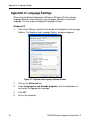
Appendix A provides solutions in the event of characters not appearing correctly due to
the interface language used.
Note: Throughout the manual, PowerMax, PowerMax+, PowerMaxPro, and
PowerMaxComplete are referred to as “PowerMax”. PowerMaster-10 and
PowerMaster-30 models are referred to as “PowerMaster”. When necessary to relate to
a specific model, this model will be mentioned specifically.
ii
DE5450S Remote Programmer Guide Rev. 9
Formatting Conventions
Formatting Conventions
The following formatting conventions are used throughout the documentation:
Note:
Additional information relevant to the presently
discussed subject.
Warning:
Caution:
Information that is essential for your safety and to avoid
damaging the hardware or software.
bold text
Indicates operations that you must perform (e.g., name
of a button to be clicked or option to be selected) or to
emphasize a field or concept being described.
DE5450S Remote Programmer Guide Rev. 9
iii
Table of Contents
Table of Contents
Copyrights & Warranty ........................................................... i
About This Manual ................................................................. ii
Formatting Conventions ........................................................ iii
Table of Contents ................................................................... iv
Chapter 1: Introduction .......................................................... 1
Chapter 2: Getting Started ...................................................... 3
2.1
2.2
2.3
2.4
2.5
2.6
Hardware / Software Requirements .............................................................. 3
Installation .................................................................................................... 3
Starting Remote Programmer ....................................................................... 4
Remote Programmer Main Window ............................................................. 4
Navigating Around Remote Programmer ..................................................... 8
Exiting Remote Programmer ........................................................................ 8
Chapter 3: Menus ................................................................... 9
3.1
3.2
3.3
3.4
3.5
3.6
Sites Menu .................................................................................................... 9
Edit Menu ..................................................................................................... 9
View Menu ................................................................................................. 10
Communications Menu............................................................................... 10
Advanced Menu.......................................................................................... 11
Help Menu .................................................................................................. 12
Chapter 4: Sites .................................................................... 13
4.1
4.2
4.3
4.4
4.5
4.6
4.7
4.8
Introduction to Sites ................................................................................... 13
Creating a New Site .................................................................................... 15
Saving a Site ............................................................................................... 20
Saving a Site File with a New Name .......................................................... 21
Displaying and Editing Existing Site Files ................................................. 21
Copying a Site ............................................................................................ 21
Deleting a Site ............................................................................................ 22
Exiting the Site List Window ..................................................................... 22
Chapter 5: Users ................................................................... 23
5.1 Adding New Users...................................................................................... 23
5.2 Deleting a User ........................................................................................... 24
5.3 Login as a Different User ........................................................................... 24
Chapter 6: Data Details Tables .............................................. 25
iv
DE5450S Remote Programmer Guide Rev. 9
Table of Contents
Data Indications ................................................................................................. 27
6.1 Site Information .......................................................................................... 27
6.2 User Settings ............................................................................................... 28
6.3 User Codes.................................................................................................. 29
6.4 Panel Defintiions ........................................................................................ 29
6.5 Communications Definitions ...................................................................... 29
6.6 PGM ........................................................................................................... 29
6.7 Internal Siren/Strobe ................................................................................... 30
6.8 X-10 General Features ................................................................................ 30
6.9 X-10 Device Settings .................................................................................. 30
6.10 External Voice Box ................................................................................... 31
6.11 Zone Enrollment ........................................................................................ 31
6.12 Siren Enrollment ........................................................................................ 32
6.13 Keyfob Enrollment (PowerCode) .............................................................. 34
6.14 Keyfob Enrollment (PowerG) ................................................................... 35
6.15 Repeater Enrollment .................................................................................. 37
6.16 Keypad Enrollment .................................................................................... 39
6.17 2W Keypad Enrollment ............................................................................. 41
6.18 Pendant Enrollment ................................................................................... 43
6.19 Zone Definitions ........................................................................................ 45
6.20 Zone Status/Trouble .................................................................................. 45
6.21 Panel Status/Trouble .................................................................................. 48
6.22 Event/History Log .................................................................................... 49
6.23 Screen Saver .............................................................................................. 49
Chapter 7: Connecting to the Control Panel .......................... 50
7.1
7.2
7.3
7.4
Defining Communication Settings ............................................................. 50
Connecting to PowerMax/PowerMaster ..................................................... 56
Online Operations ....................................................................................... 58
Disconnecting from the PowerMax/PowerMaster...................................... 60
Chapter 8: Data .................................................................... 61
8.1 Defining Data Settings................................................................................ 61
8.2 Using Customized Full Upload/Download Data ........................................ 62
Chapter 9: Two Download Codes .......................................... 63
9.1 How It Works ............................................................................................. 63
9.2 Operation .................................................................................................... 63
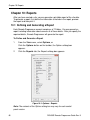
Chapter 10: Reports.............................................................. 66
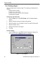
10.1 Defining and Generating a Report ............................................................ 66
10.2 Viewing a Report ...................................................................................... 67
10.3 Printing a Report....................................................................................... 68
DE5450S Remote Programmer Guide Rev. 9
v
Table of Contents
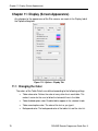
Chapter 11: Display (Screen Appearance) ............................. 70
11.1
11.2
11.3
11.4
Changing the Color................................................................................... 70
Column Alignment ................................................................................... 71
User Interface Language ........................................................................... 71
File Naming .............................................................................................. 72
Chapter 12: Troubleshooting ................................................ 73
Appendix A: Language Settings ............................................ 76
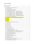
Index
77
vi
DE5450S Remote Programmer Guide Rev. 9
Chapter 1: Introduction
Chapter 1: Introduction
The Visonic Remote Programmer is a utility program that enables you to manage
the PowerMax/PowerMaster alarm system from a remote station. It runs on IBMPC or compatible workstations and runs on Microsoft® Windows® 7 (32 or 64-bit),
Microsoft® Windows® 8 Desktop (32 or 64-bit) and Windows XP.
The Remote Programmer works with the new PowerG wireless technology and
PowerMaster alarm systems for intrusion alarm systems. When connected to
Visonic’s PowerG-based systems, the program provides superior diagnostic and
configuration capabilities, including performing walk-test from a remote location,
diagnostics of wireless network condition and complete configuration of all peripheral
devices in addition to configuring the alarm system control panel.
The Remote Programmer continues to support PowerCode-based systems and
PowerMax alarm systems.
Remote Programmer allows offline preparation of specifications, each of which is a
set of parameters especially tailored for a particular installation site. After preparing
the configuration, the remote programmer can download it into the alarm system
control panel locally using a cable or remotely via telephone.
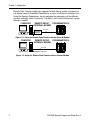
Remote Programmer communicates with PowerMax and PowerMaster alarm
systems in two ways, as follows:
•
locally through an USB/UART adapter that converts the signals to UART
TTL levels, as shown in figure 1-1,
•
or, remotely via telephone lines and a modem, as shown in figures 1-2 and
1-3.
Local Data Transfer enables the operator to prepare the parameters for the alarm
system on a PC where he specifies parameters in the Site Screens, even though he
is working at the same installation site. He then transfers the data to the alarm
system through a cable.
COMPUTER
POWERMASTER-10
LOCAL SETUP
UART
USB
UART
no modem is
OVER
UART
required for
USB ADAPTER TTL
local download
Figure 1-1: Setup for Local Data Transfer
DE5450S Remote Programmer Guide Rev. 9
1
Chapter 1: Introduction
Remote Data Transfer enables the operator to work from a remote site where he
can control several PowerMax/PowerMaster systems at different installation sites.
Using the Remote Programmer, he can compare the parameters of the different
systems and copy them if necessary. The data is then transferred to each system
through a modem.
REMOTE SETUPPOWERMASTER-10
COMPUTER
EXTERNA L MODEM
TEL. LINE
EXTERNAL
MODEM
RS-232 CABLE
Figure 1-2: Setup for Remote Data Transfer with an External Modem
COMPUTER
REMOTE SETUPINTERNA L MODEM
POWERMASTER-10
TEL. LINE
MODEM’S LINE JACK
Figure 1-3: Setup for Remote Data Transfer with an Internal Modem
2
DE5450S Remote Programmer Guide Rev. 9
Chapter 2: Getting Started
Chapter 2: Getting Started
2.1 Hardware / Software Requirements
In order to run Remote Programmer, you need the following resources:
·
PC (2GHz or higher)
·
Microsoft® Windows® 7, 8 or XP.
·
1GB RAM
·
At least 20 MB of free disk space.
·
For best performance, use a display driver with a resolution of at least 1024 x
768 pixels.
2.2 Installation
Install an internal modem in the computer, or use an RS-232 cable to connect an
external modem to one of the computer’s COM ports as instructed in the manual
supplied with the modem. Then connect the modem to the telephone line. The
modems suitable for use with Remote Programmer are listed in the Modem field in
the Communications tab of the Options window (refer to 7.1.2 Remote Connection).
To Install Remote Programmer
Attention: If an older version of the Remote Programmer software is already
installed on your PC, uninstall it before installing the new software version.
1.
Start Windows. Close all running applications, if any.
2.
Insert the Remote Programmer DVD into the DVD drive.
If your system includes the AutoPlay feature, the setup program starts
automatically. Otherwise, proceed as follows:
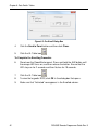
3.
From the Start menu, select Run; the Run dialog box appears.
4.
In the Run edit box, type the drive letter of the DVD drive you are using,
followed by a colon, backslash, and the word “setup”, for example:
"d:\setup".
5.
Click OK. The installation welcome screen appears and the Installation
program guides you through the entire process.
6.
Click Next, then follow the instructions on your screen to complete the
installation.
7.
Restart your computer when the Installation wizard prompts you to do so.
During installation a PowerMax/PowerMaster shortcut icon is placed
on the Desktop to enable you to start Remote Programmer easily.
DE5450S Remote Programmer Guide Rev. 9
3
Chapter 2: Getting Started
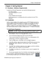
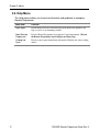
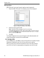
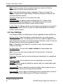
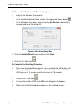
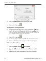
2.3 Starting Remote Programmer
1.
On the Windows Desktop, double-click on the Remote Programmer
icon; the Login screen appears.
Figure 2-1: Login Screen
2.
In the Operator edit box, type visonic.
3.
In the Password edit box, type powermax, then click OK.
Both entries are case-sensitive - use lowercase letters.
The main Remote Programmer screen appears with the most uploaded
recent PowerMax/PowerMaster configuration, including current zone
enrollment.
This window enables you: to open an existing site file; create a new site file; copy a
site file; delete a site file or exit the program. Refer to “Chapter 4. Sites” for further
details.
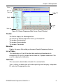
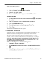
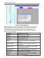
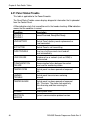
2.4 Remote Programmer Main Window
The Remote Programmer main window displays all the main features of Remote
Programmer. This enables you to manage the PowerMax/PowerMaster alarm
system easily and efficiently.
4
DE5450S Remote Programmer Guide Rev. 9
Chapter 2: Getting Started
Title bar
Menu bar
Tool bar
Table Data
Details
List of
Tables
Status bar
Screen
Tabs
Figure 2-2: Remote Programmer Main Screen (PowerG Version)
Title Bar
·
·
·
·
The title bar displays the following features:
The name of the Remote Programmer file that you have opened.
The windows Minimize button.
The windows Maximize button.
The windows Close button.
Menu Bar
Displays the menus that enable you to access Remote Programmer features.
List of Tables
This area displays a list of all the data tables containing information which
characterizes the site. As you point to each table title, it appears underlined. Click
on a title to display that table data.
Table Data
This area contains detailed data included in the selected table.
Type in settings, or double-click on the down-pointing arrow to display a drop-down
list, and select the appropriate value.
DE5450S Remote Programmer Guide Rev. 9
5
Chapter 2: Getting Started
Toolbar
Remote Programmer provides a toolbar that displays buttons which are shortcuts to
the most frequently used features of the system.
Button
Name
Function
Also accessible
through menu
New
Displays the New Sites window.
Sites
Sites
Displays the Sites List window.
Sites
Save
Saves the site file displayed on the
screen.
Sites
Search
Displays the Sites window (without Site
information).
View Sites
Options
Displays the Options dialog box.
View
Back
Displays the previous table according to
the List of Tables.
View
Next
Displays the next table according to the
List of Tables.
View
Login /
Logout
Connects/disconnects the Remote
Programmer to/from the control panel.
Communications
Download
Downloads data from the Remote
Programmer to the control panel.
Communications
Upload
Uploads data from the control panel to the Remote
Communications
Programmer and automatically updates files.
Note: To upload event logs/scheduler in
PowerMax+, see Chapter 8: Data.
Download
Table
Downloads data from the table currently visible on
Upload Table
Uploads data from the control panel to the table
Communications
the screen to the control panel.
Communications
currently visible on the screen (available in
PowerMax+ only).
6
DE5450S Remote Programmer Guide Rev. 9
Chapter 2: Getting Started
Button
Name
Function
Also accessible
through menu
Help
Displays the Remote Programmer Help files.
Help
Device
Configuration
Performs device configuration.
-
Stop
Terminates device configuration procedure.
-
P. Test
Starts a walk-test on the enrolled zones or
devices referred to in the displayed table. The
test starts after you initiate it on the device
Status Bar
The Status Bar appears at the bottom of the Remote Programmer screen. It
displays the following:
·
Menu name
·
Caps lock
·
Number lock
·
Communication Status: The communication status is displayed by the color
of the two communication status icons:
Program Status
Left Icon
Right Icon
Communication is offline
Gray
Gray
Communication is online
Dark
green
Dark
green
Downloading to control panel
Dark
green
Light
green
Uploading from control panel
·
·
Light
Dark
green
green
PowerMax/PowerMaster model name.
Control Panel State: Displays the control panel state. This can be one of
nine states: disarm, exit delay home, exit delay away, entry delay, home,
away, user test, download and programming.
DE5450S Remote Programmer Guide Rev. 9
7
Chapter 2: Getting Started
2.5 Navigating Around Remote Programmer
You can move around the Remote Programmer screen and carry out functions in a
variety of ways:
Mouse
·
·
·
·
Use the mouse to point to a position on the screen, then click the left mouse
button. This enables you to do the following:
Click a button.
Select a table tab in the main screen.
Place the cursor within a table edit box.
Display a drop-down list.
Arrow keys
The arrow keys enable you to move around the Remote Programmer tables and
highlight the edit boxes. However, they do not enable you to place the cursor at the
insertion point; you must do that with the mouse or by pressing Enter.
2.6 Exiting Remote Programmer
At any time, you can exit Remote Programmer.
To Exit the Program
8
1.
From the Sites menu, select Exit. A popup message appears
prompting you to save the recent changes to the system.
2.
Click Yes to save or No to disregard recent changes. Remote
Programmer closes.
DE5450S Remote Programmer Guide Rev. 9
Chapter 3: Menus
Chapter 3: Menus
The Remote Programmer main screen displays six menus, which enable you to
access the different features of the application.
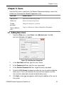
3.1 Sites Menu
The Sites menu provides you with the tools to manage new and existing Sites.
Menu Item
Function
List of Sites
Displays the Sites window (with Site information).
New Site
Displays a new Remote Programmer Site File that contains default
values.
Search
Displays the Sites window (without Site information).
Save
Saves an existing Site file.
Save As
Enables you to save a site file by a new name.
Close Site
Closes the currently opened site
Print
Prints a report.
Print Preview
Displays the report on the screen before you print it.
Print Setup
Enables you to determine the Print specifications.
User
Enables you to manage users.
Exit
Exits Remote Programmer.
3.2 Edit Menu
The Edit menu contains commands that help you edit and fill in details in each
screen.
Menu Item
Function
Cut
Removes selected text to a temporary memory known as a clipboard.
Copy
Copies selected text to the clipboard.
Paste
Places the text being held in the clipboard at the point of insertion.
DE5450S Remote Programmer Guide Rev. 9
9
Chapter 3: Menus
3.3 View Menu
The View menu contains items that enable you to control the appearance of your
Remote Programmer screen.
Menu Item
Function
Toolbar
Displays or hides the Tool bar
Status Bar
Displays or hides the Status bar.
Next Table
Displays the next table of the List of Tables.
Previous Table
Displays the previous table of the List of Tables.
Messages
Window
Displays the incoming and outgoing messages.
Options
Displays the Options dialog box.
3.4 Communications Menu
The Communications menu enables you to manage the Communication process
with the control panel. All of these functions appear on the toolbar.
Menu Item
Function
Login/Logout
Begins the login/logout process to/from the control panel.
Update Login
Data…∗
Enables updating the download and installer code when system is armed.
Download
Downloads data from the Remote Programmer to the control panel.
Upload
Uploads data from the control panel to the Remote Programmer. (In
PowerMax+, this process uploads all parameters except for the Event Log.
To upload the Event Log use Upload Table)
Download Table
Downloads the currently displayed table from the Remote Programmer to the
control panel.
Upload Table∗∗
Uploads the currently displayed table from the control panel to the Remote
Programmer.
Change System
Time & Date…
Sets the time and the date that will be downloaded to the control panel. This
option is only enabled when the communication between Remote Programmer
and the control panel is enabled.
Update Time &
Date On Logout
Automatically updates the control panel date and time when disconnecting
from the control panel
∗
Available in PowerMax only.
∗∗
Available in PowerMax+ only.
10
DE5450S Remote Programmer Guide Rev. 9
Chapter 3: Menus
Customize
Zone/Sensor
Names∗∗
Enables modification of the five custom names.
Upload
Customized
Zone/Sensor
Names∗∗
Retrieves the updated custom names from the PowerMax/PowerMaster.
Port Auto
Detection…
Automatically begins a search for the control panel that is connected by Serial
Communication mode.
Settings
Opens the Options dialog box, on the Communications tab.
3.5 Advanced Menu
The Advanced menu includes items that enable you to receive additional control
panel information.
∗∗
Menu Item
Function
Power
Commander∗∗
Enables you to receive information on the status of the control panel and to
set its state. Enabled only when working online.
Settings
Opens the Options dialog box, on the Advanced tab.
Soak Test∗∗∗
Enables you to receive information on selected zones that have been tested, as
follows:
Get Active Zones: Displays the list of zones currently active in Soak Test
mode.
Get Failed Zone: Displays the list of zones that failed to complete the Soak
Test.
Delete Failed Zone: Clears the list of zones that failed to complete the Soak
Test.
Get Time 2 End: Displays the time remaining for each zone to complete the
Soak Test for every zone.
Available in PowerMax+ only.
∗∗∗
Available in PowerMaster only.
DE5450S Remote Programmer Guide Rev. 9
11
Chapter 3: Menus
3.6 Help Menu
The Help menu enables you to receive information and guidance in managing
Remote Programmer.
12
Menu Item
Function
Help Topics
On-line Help to increase your knowledge about Remote Programmer, and
help you use it to its maximum potential.
About Remote
Programmer
Provides Remote Programmer copyright and version information. Click on
the Remote Programmer logo to display our Home Page.
Catalog and
Serial
Provides control panel manufacture information. Enabled only when working
online.
DE5450S Remote Programmer Guide Rev. 9
Chapter 4: Sites
Chapter 4: Sites
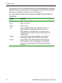
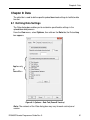
4.1 Introduction to Sites
The Remote Programmer enables you to manage security system installation sites
in a variety of ways. These features are accessible either from the menus or from
the Site List window.
The Site List window is displayed either when the program is first
initiated, or by clicking the Sites button in the tool bar or by selecting
List of Sites in the Sites menu.
Note: The Site List window opens with data contained in the folder of
the Sites Location.
or
Click the Search button in the tool bar or by selecting Search in the
Sites menu.
Note: The Site List window opens with no data.
Figure 4-1: Site List Window
This window displays a list of the site names whose files are located in the
directory displayed in the Sites Location field. The first time the program is initiated,
the path displayed will be the path where the Remote Programmer is installed on
your computer. In later sessions, the Sites Location field will display the path last
chosen (either typed in or selected using the Browse button). Using the Browse
button, it is possible to locate and access a site file anywhere in the network and
not just access site files saved to your local computer.
DE5450S Remote Programmer Guide Rev. 9
13
Chapter 4: Sites
Each column of the site list table can be sorted in either descending or ascending
order by clicking on the column title. You can drag the vertical lines that separate
the columns to enlarge or reduce the size of the columns.
The screen displays buttons, which enable you to begin working with Remote
Programmer:
Button
Function
Open
Opens an existing Site
New
Opens a new Site
Delete
Deletes a Site
Exit
Closes the Remote Programmer application. When you
display the Sites List from within the system, the Exit
button appears as a Cancel button. This enables you to
remove the Sites List from the screen, and continue using
the application.
Opens the Browse for Folder dialog box, which enables
you to locate a folder where the Site files are located.
Lists all the file names containing the text entered into the
Search window. If "Look in sub directories" is not checked,
the search will be performed only on Sites location (the root
directory).
Browse
Search
14
DE5450S Remote Programmer Guide Rev. 9
Chapter 4: Sites
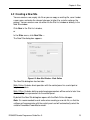
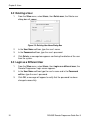
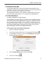
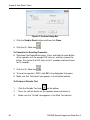
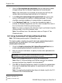
4.2 Creating a New Site
You can create a new, empty site file or you can copy an existing file, save it under
a new name, and make the relevant changes to tailor it to a similar setup as the
original. You can create a new site either via the Site List window or directly in the
New Site window.
Click New in the Site List window,
or
In the Sites menu, click New Site.…
The New Site dialog box appears.
Figure 4-2: New Site Window - Work Online
The New Site dialog box has two tabs:
Work Online: Enables direct operation with the control panel via a serial port or
telephone modem.
Work Offline: Enables defining and changing parameters offline and at a later time
downloading these parameters to the control panel.
By default the New Site dialog box opens with the Work Online tab open.
Note: It is recommended to work online when creating a new site file, so that the
software will communicate with the control panel and will automatically select the
suitable PowerMax/PowerMaster model.
DE5450S Remote Programmer Guide Rev. 9
15
Chapter 4: Sites
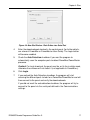
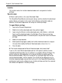
Working Online
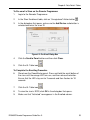
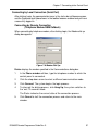
To work via a serial port
1.
In the New Site window click Options…. The Options window
appears.
Figure 4-4: Options - Serial Port Communications Mode
2.
Ensure that Serial port is selected in the Communication mode field
and that the serial port details are correct (refer to chapter 7: Connecting
to the Control Panel for further details).
3.
Click OK.
The New Site window will appear displaying the Work Online tab with the
Phone Number field disabled and the Auto detection checkbox enabled.
16
DE5450S Remote Programmer Guide Rev. 9
Chapter 4: Sites
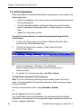
Figure 4-4: New Site Window - Work Online via a Serial Port
4.
Enter the download code located in the control panel (for further details,
see relevant PowerMax or PowerMaster User Guide). The Login button
will become enabled.
5.
Check the Auto Detection checkbox if you want the program to
automatically scan the computer ports to detect PowerMax/PowerMaster
presence.
Caution! For local download, the panel must be set to the installer mode,
otherwise the software will not detect it (not applicable to PowerMax+).
6.
Click Login.
7.
If you marked the Auto Detection checkbox, the program will start
scanning the different ports to look for a PowerMax/PowerMaster and will
then connect to the panel and verify the download code.
If you did not mark the auto detection checkbox, the program will try to
connect to the panel via the serial port defined in the Communications
settings.
DE5450S Remote Programmer Guide Rev. 9
17
Chapter 4: Sites
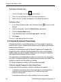
To work via a telephone modem
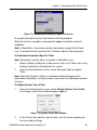
1.
In the New Site window click Options…. The Options Communications
dialog box will appear.
Figure 4-5: Options - Telephone Modem Communications Mode
2.
Select Telephone modem in the Communications mode field.
3.
Click OK.
The New Site window will appear displaying the Work Online tab with the
Phone Number field enabled and the Auto detection checkbox disabled.
18
DE5450S Remote Programmer Guide Rev. 9
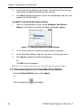
Chapter 4: Sites
Figure 4-6: New Site Window - Telephone Modem Mode
4.
Enter the Phone Number and the Download Code located in the
control panel (for further details, see PowerMax or PowerMaster
User Guide).
The Login button will become enabled.
5.
Click Login. The Modem Dial Up... window will appear and attempt
connecting.
Figure 4-7: Modem Dial Up...
DE5450S Remote Programmer Guide Rev. 9
19
Chapter 4: Sites
Working Offline
Work Offline only if you know the panel model you want to connect to.
1.
Select the Work Offline tab. The following screen will be displayed:
Figure 4-8: New Site Window - Work Offline
2.
Select the relevant panel model.
Note: The Work Offline dialog box first lists all existing
PowerMax/PowerMaster models. Select each model you do not require
and click the Remove button to delete the model from the list. To reset
the list, click the Load button.
3.
Click OK.
The Remote Programmer main screen will appear and the table data details will
include the parameters relevant for the selected model.
4.3 Saving a Site
From the Sites menu, select Save, or click the Save button on the toolbar; Remote
Programmer automatically saves the site file on which you are working.
When you select Save or click the Save button for the first time after creating a
new site file, the Save As screen prompts you to provide a new site file name.
20
DE5450S Remote Programmer Guide Rev. 9
Chapter 4: Sites
4.4 Saving a Site File with a New Name
This enables you to save the site file with a new name and in a different directory.
1.
From the Sites menu, select Save As; Remote Programmer
displays the Save As screen.
2.
Enter a suitable name for the new site and locate the directory
where you want to save the file.
Note: In the Option - Display tab (see Chapter 11), if the File Naming section is
checked, the file name must include the account number. If the File Naming edit
box is not checked, it can be assigned any name.
4.5 Displaying and Editing Existing Site Files
Once you have created a site, and saved it, you can view it at any time.
1.
Either select the site from the recently used files in the Sites menu
or in the Sites List window, select the site name to display and click
Open.
2.
The Remote Programmer main window appears, and displays the
site tables of the selected site.
3.
Edit the site tables as necessary.
4.6 Copying a Site
You can create a new site based on an existing similar site. This is done by
copying an existing site file, saving it with a new name and then making and saving
the necessary changes.
1.
In the Site List window, select an existing site file.
2.
Click Copy; an edit box appears prompting you for the name of the
new site.
3.
Type the new site name, then click OK.
The Remote Programmer main window appears and displays the
details of the copied site.
4.
Edit the site as necessary.
5.
Click Save to save the site.
DE5450S Remote Programmer Guide Rev. 9
21
Chapter 4: Sites
4.7 Deleting a Site
When a Site is no longer active, and it is no longer necessary to store it in Remote
Programmer, you can delete it.
1.
In the Sites List, select the site to delete, then click Delete, a
warning box appears reminding you that any account that you
delete is not retrievable.
2.
Click Yes to delete the account, or No to return to the Sites List.
If you click Yes, the Remote Programmer main window appears and
displays the last site that was opened.
4.8 Exiting the Site List Window
When you open Remote Programmer, the Sites List displays an Exit button.
However, when you display the Sites List from within the application, the Exit
button is replaced by a Cancel button.
Click Exit to exit Remote Programmer.
Click Cancel; the Sites List closes, and the main Remote Programmer screen
becomes active.
22
DE5450S Remote Programmer Guide Rev. 9
Chapter 5: Users
Chapter 5: Users
From the Sites menu, select Users; the Remote Programmer displays a menu that
enables you to manage the Remote Programmer users.
Menu Item
Enables you to:
Add new user
Add a new user name and password.
Delete user
Delete a user name and password.
Change
password
Change an existing user’s password.
Login as different
user
Login as a different user without exiting Remote Programmer.
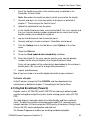
5.1 Adding New Users
1.
From the Sites menu, select Users, then Add new user; the Add
new user dialog box will appear.
Figure 5-5: Add New User Dialog Box
2.
In the User Name edit box, type the user's name.
3.
In the Password edit box, type the user's password.
4.
In the Confirm Password edit box, retype the user's password.
5.
Check the Full Access checkbox to enable the user to create and delete
other users. If this is not checked, the user will have access to all the
sites, but will not be able to create or delete other users.
6.
Click Add; a message box appears confirming the addition of the user to
the system.
DE5450S Remote Programmer Guide Rev. 9
23
Chapter 5: Users
5.2 Deleting a User
1.
From the Sites menu, select Users, then Delete user; the Delete user
dialog box will appear.
Figure 5-2: Deleting User Name Dialog Box
2.
In the User Name edit box, type the user's name.
3.
In the Password edit box, type the user's password.
4.
Click Delete; a message box appears confirming the deletion of the user
from the system.
5.3 Login as a Different User
24
1.
From the Sites menu, select Users, then Login as a different user; the
Remote Programmer Login screen appears.
2.
In the User Name edit box type the user's name and in the Password
edit box type the user's password.
3.
Click OK; a message will appear to notify that the password has been
changed successfully.
DE5450S Remote Programmer Guide Rev. 9
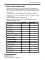
Chapter 6: Data Details Tables
Chapter 6: Data Details Tables
The data details tables display the parameters that can be uploaded from or
downloaded to the PowerMax/PowerMaster control panel. When first creating a
site file, the values displayed are default values, which can be altered to suit the
specific system.
Use the arrow keys to navigate between the cells and focus on the different
parameters, then click the left mouse button or press ENTER to edit the cell and
change the values.
Remote Programmer includes the following tables:
Note: The table and their contents can change according to the different
PowerMax/PowerMaster models.
PowerMax
PowerMaster
Site Information
User Settings
User Codes
Operation Mode
--
Panel Definitions
Communications Definitions
PGM
Internal Siren/Strobe
--
X-10 General Features∗
X-10 Device Settings∗∗
Define PowerLink
--
External Voice Box
RF Diagnostics
--
Zone Enrollment
--
Siren Enrollment
∗ Available in PowerMax+ only
∗ ∗ Available in PowerMax+ only
DE5450S Remote Programmer Guide Rev. 9
25
Chapter 6: Data Details Tables
26
PowerMax
PowerMaster
Keyfob Enrollment
Repeater Enrollment
--
1W Keypad Enrollment
--
2W Keypad Enrollment
Pendant Enrollment
--
Keyfob Definitions
--
Keypad Definitions
--
Siren Definitions
--
Prox Tag Definitions
Zone Definitions - Motion
--
Zone Definitions - Contact
--
Zone Definitions - Smoke
--
Zone Definitions - Camera
--
Zone Definitions - Flood
--
Zone Definitions - Gas
--
Zone Definitions - Hard Wired
--
Zone Definitions - Temperature
--
Zone Definitions - Shock
--
Zone Status/Trouble
--
Panel Status/Trouble
--
History Event Log
Panel Event Log
Screen Saver
DE5450S Remote Programmer Guide Rev. 9
Chapter 6: Data Details Tables
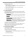
Data Indications
This table is applicable to the PowerG models.
The various data tables display data that has been uploaded to the remote
management from the PowerMaster system’s various devices, such as the
control panel, detectors, keyfobs, and sirens. When configuration or status
data is modified and/or downloaded, the table entries are color coded to
indicate the status of the displayed information:
•
Green – Data remains unchanged.
•
Red – Data has changed since the last upload.
•
Yellow – Data upload is in process – when finished, the entry turns to
green or red accordingly.
•
Gray – This parameter is not applicable to the device.
6.1 Site Information
Site Information displays general information about the site control panel.
Panel Site Name: The name of the site where the control panel is installed. By
default this field receives the name of the detected panel model.
System Manager: The name of the System Manager responsible for programming
the control panel, responding to alarms and other events.
Address, City, State, and Zip Code: The complete address of the site.
Panel Phone No.∗: The telephone number which the PC modem uses to connect
to the control panel.
Additional Information: Additional important information about the
PowerMax/PowerMaster site and facilities.
Primary Phone No.∗∗: The first telephone number the control panel dials.
Primary Communication Mode∗∗: The mode used to call a primary telephone
number.
Secondary Phone No.∗∗: When the primary telephone number is engaged, the
Remote Programmer dials this telephone number.
Secondary Communication Mode∗∗: The mode used to call a secondary telephone
number.
∗ Available in PowerMax only.
∗ ∗ Available in PowerMax+ only.
DE5450S Remote Programmer Guide Rev. 9
27
Chapter 6: Data Details Tables
Note: If there is no entry for the secondary telephone number, the Remote
Programmer will dial the primary telephone only.
Note: If the dialed telephone number is engaged or there is no answer, the
Remote Programmer will toggle between the primary telephone number and the
secondary telephone number.
Time Zone: Select from the list the relevant time zone.
Download Code: A 4-digit password, including letters A-F, used to enable
downloading data to the control panel. In the PowerG version, you can set
separate passwords for the Master Installer and the Installer.
Installer Code: A 4-digit password used to manage the control panel via the built-in
keypad. In the PowerG version, you can set separate passwords for the Master
Installer and the Installer.
6.2 User Settings
User Settings enables you to define panel settings, applicable to each individual site.
Set User Tel No.: Type the telephone number where the user can be reached
while away from the site. The control panel will call this number to report the event
types defined by the installer in the Communications Definitions screen. Do not use
any parentheses or dashes when typing the number.
Note: In PowerMax+ and PowerG, it is possible to enter 4 private telephone
numbers in this table.
Set Voice Option: You can either enable or disable the voice prompts and
messages.
Note: You can only hear voice prompts from the control panel, not from the
Remote Programmer.
Autoarm∗∗: You can select to arm the control panel automatically (at a predefined
time).
Auto Arm Time∗∗: You can define the time to automatically arm the system.
Squawk∗∗: You can enable or disable the squawk (short siren sound) option upon
arming and disarming.
Time Format∗∗: You can adjust the control panel built-in clock to show the time in
European format (hh:mm) or US format (hh:mm AM/PM).
Date Format∗∗: You can adjust the control panel built-in calendar date to show the
date in European format (dd/mm/yyyy) or US format (mm-dd-yyyy).
∗ ∗ Available in PowerMax+ only.
28
DE5450S Remote Programmer Guide Rev. 9
Chapter 6: Data Details Tables
6.3 User Codes
This table defines the PowerMax/PowerMaster users and lists their codes. Only
users, whose numbers and codes are listed in this screen, can activate the control
panel. PowerMax and PowerMaster-10 can store up to 8 user numbers and codes.
PowerMaster-30 can store up to 48 user numbers and codes. All User codes must
be different from the Duress code and Installation code.
User Number 1 is known as the Master User. He is the only user who has the
authority to modify the User Settings and User Codes screens. The Master User
code cannot be 0000.
To Enter a User Code
1.
Identify the user number you wish to define.
2.
Enter a four-digit code that is unique to the selected user number.
3.
Enter comments and additional information about this user.
4.
If Partitions are enabled (in the Site Information screen), choose the
partition(s) that this user is allowed to arm and disarm:
1, 2, 3, 1+2, 1+3, 2+3, 1+2+3
6.4 Panel Defintiions
Panel Definitions enables you to customize the control panel and adapt its
characteristics and behavior to the requirements of the particular user.
6.5 Communications Definitions
Communications Definitions enables you to set the telephone communication
parameters to the requirements of the particular Site.
6.6 PGM
PowerMax/PowerMaster control panels can open or close the programmable
(PGM) output as a result of a certain event or condition. This table enables you to
determine the events and conditions under which the PGM (programmable)
outputs will function.
Note: In some versions of the PowerMax+, the PGM will also include a scheduler,
(see 6.9 X-10 Device Settings for further details). When the X-10 device settings
table is uploaded, the Remote Programmer will also load the PGM table. However,
this does not occur the other way around.
DE5450S Remote Programmer Guide Rev. 9
29
Chapter 6: Data Details Tables
6.7 Internal Siren/Strobe
This defines the operation of the INT output in the control panel.
Internal Siren - enables you to activate the output for a certain amount of (Bell)
time. Strobe - activates the output until the system is disarmed.
6.8 X-10 General Features∗
This screen enables you to set the general features for the X-10 units. The House
Code must be a letter between A and P that distinguishes this particular PowerMax
X-10 unit from others.
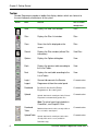
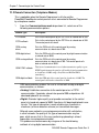
6.9 X-10 Device Settings∗∗
PowerMax control panel can control X-10 units. This screen enables you to
determine settings for each applicable device.
Some versions of the PowerMax+ include a scheduler that enables you to set
specific times for switching the lights on and off and can also be used with the
PGM. The scheduler allows four regular daily settings and four additional settings
per day.
Figure 6-1: Scheduler
Note: To download/upload the X-10 device settings, you need to select this table
and press the download/upload table button. For further information, see Chapter
8: Data.
Note: When the X-10 device settings table is uploaded, the Remote Programmer will
also load the PGM table. However, this does not occur the other way around.
∗ Available in PowerMax+ only
∗ ∗ Available in PowerMax+ only
30
DE5450S Remote Programmer Guide Rev. 9
Chapter 6: Data Details Tables
6.10 External Voice Box
The PowerMax Speech Box is a device that enables home occupants to hear
notifications and converse with the central station from areas of the home that the
panel’s built-in speakers and microphones do not reach.
This table indicates whether or not a voice box is installed and is the only voice
device enabled for communication, or if it is mixed within the protected area.
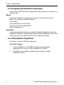
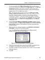
6.11 Zone Enrollment
This table is applicable to the PowerG models.
This table displays information about the enrollment status and diagnostic quality
of the various wireless zones registered in the system. The information includes
the zone number, device installed in the zone and RF ID, enrollment status, the
zone type (Contact; Motion; Smoke, etc.), received signal strength indication (24hour and current RSSI) quality of the device (Strong; Good; Poor; or Not OK),
device configuration, walk-test and a temperature walk-test.
To Pre-enroll a Zone on the Remote Programmer
1.
Login to the Remoter Programmer.
2.
In the Zone Enrollment table, click an “Unregistered” Action button
3.
In the dialog box that opens, make sure the Add Device radio button is
selected and enter the zone ID.
.
Figure 6-1: Pre-Enroll Dialog Box
4.
Click the Send to Panel button and then click Close.
5.
Click the UL Table icon
DE5450S Remote Programmer Guide Rev. 9
.
31
Chapter 6: Data Details Tables
To Complete the Enrolling Procedure
6.
Stand near the PowerMaster panel. Press and hold the enroll
button of the device until the orange LED turns on, and then release
the button. Ensure that the LED stays on for 2 seconds and then
flashes for 10 seconds.
7.
Click the UL Table icon
8.
To view the zone’s RSSI, click OK in the dialog box that opens.
9.
Make sure that “Activated” now appears in the Enrolled column.
.
To Perform a Periodic Test
1.
Click the Periodic Test icon
2.
Press the tamper switch of the device once and release it.
3.
Make sure that “Tested” now appears in the Walk Test column.
on the toolbar.
To Delete a Zone
of the zone
1.
In the Zone Enrollment table, click the Action button
to be deleted.
2.
From the dialog box, select the Delete Device radio button.
3.
Click the Send to Panel button.
4.
A new dialog box opens asking Are you sure?; click Yes.
5.
Click Close.
The zone is now deleted from the system.
6.12 Siren Enrollment
A siren is a two-way wireless unit which emits a loud siren and flashes a
bright light in the event of a burglary.
This table displays information about all installed sirens and their enrollment status.
For PowerG installations, the data also includes the siren number and RF ID, the
siren type, received signal strength indication (24-hour and current RSSI) quality of
the device (Strong; Good; Poor; or Not OK), device configuration and walk-test.
32
DE5450S Remote Programmer Guide Rev. 9
Chapter 6: Data Details Tables
To Pre-enroll a Siren on the Remote Programmer
1.
Login to the Remoter Programmer.
2.
In the Siren Enrollment table, click an “Unregistered” Action button
3.
In the dialog box that opens, make sure the Add Device radio button is
selected and enter the siren ID.
.
Figure 6-2: Pre-Enroll Dialog Box
4.
Click the Send to Panel button and then click Close.
5.
Click the UL Table icon
.
To Complete the Enrolling Procedure
6.
Stand near the PowerMaster panel. Press and hold the enroll button of
the siren until the orange LED turns on, and then release the button.
Ensure that the LED stays on for 2 seconds and then flashes for 10
seconds.
7.
Click the UL Table icon
8.
To view the siren’s RSSI, click OK in the dialog box that opens.
9.
Make sure that “Activated” now appears in the Enrolled column.
DE5450S Remote Programmer Guide Rev. 9
.
33
Chapter 6: Data Details Tables
To Perform a Periodic Test
1.
Click the Periodic Test icon
on the toolbar.
2.
Press the self-test button on the siren once and release it.
3.
Make sure that “Tested” now appears in the Walk Test column.
To Delete a Siren
1.
In the Siren Enrollment table, click the Action button
deleted.
2.
From the dialog box, select the Delete Device radio button.
3.
Click the Send to Panel button.
4.
A new dialog box opens asking Are you sure?; click Yes.
5.
Click Close.
of the siren to be
The siren is now deleted from the system.
6.13 Keyfob Enrollment (PowerCode)
A Keyfob transmitter is a multi-button wireless unit. They enable the carriers to
perform certain system functions quickly without using the keypad, and therefore
improve system efficiency.
In order that the control panel and the Remote Programmer will recognize the
Keyfob transmitters, each one must be enrolled in the system, and assigned a
keyfob number in the panel. Keyfob initiated events are subsequently identified
and registered with reference to these numbers.
This table displays the keyfob ordinal number, the name of the user carrying this
transmitter, an indication whether the keyfob has been enrolled, the keyfob ID, the
keyfob sync. counter and the keyfob sync. backup.
The Remote Programmer enables enrolling and deleting keyfobs.
To Enroll a Keyfob Transmitter to the Control Panel
In order to perform this procedure , collect the following items together:
A PowerMax control panel, which will be used to pass the keyfob identifying
information from the keyfob through to the PC and from there to the
customer’s control panel.
The keyfob transmitter that is to be enrolled and sent to the customer.
34
DE5450S Remote Programmer Guide Rev. 9
Chapter 6: Data Details Tables
1.
Enroll the keyfob transmitter to the control panel as detailed in the
PowerMax Installer Guide.
Note: Remember the keyfob number to which you enrolled the keyfob.
2.
Connect and log in via serial connection to the panel as detailed in
chapter 7: “Connecting to the Control Panel”.
3.
Upload the keyfob data from the panel.
4.
In the Keyfob Enrollment table, enter the keyfob ID, the sync. counter and
the sync. counter backup numbers displayed on the screen next to the
keyfob number you enrolled the keyfob to.
5.
Log out and disconnect from the control panel.
6.
Connect and log in to your customer’s PowerMax control panel.
7.
Click the Options icon in the tool bar or select Options in the View
menu.
8.
Select the Data tab.
9.
Check the Send updated data immediately checkbox.
10.
Enter the keyfob ID, the sync. counter and the sync. counter backup
numbers to the relevant keyfob in the Keyfob Enrollment table.
Every cell you update will be automatically downloaded to the customer’s
control panel. (Be sure not to change other parameters.)
11.
Logout and disconnect.
Now all you have to do is to send the keyfob transmitter to your customer!
To Delete a Keyfob
In the ID column, change the ID to 00000000, and then download to the
control panel as detailed in chapter 7: Connecting to the Control Panel.
6.14 Keyfob Enrollment (PowerG)
Keyfobs, such as KF-234 PG2 and KF-235 PG2 are two-way 4-button keyfobs
used for arming/disarming of the system and for viewing system status (KF-235
PG2).
The table displays information about all installed keyfobs and their enrollment
status. The data also includes the keyfob number and RF ID, received signal
strength indication (24-hour and current RSSI) quality of the device (Strong; Good;
Poor; or Not OK), device configuration and walk-test.
The Remote Programmer enables pre-enrolling and deleting keyfobs.
DE5450S Remote Programmer Guide Rev. 9
35
Chapter 6: Data Details Tables
To Pre-enroll a Keyfob on the Remote Programmer
1.
Login to the Remoter Programmer.
2.
In the Keyfob Enrollment table, click an “Unregistered” Action button
3.
In the dialog box that opens, make sure the Add Device radio button is
selected and enter the keyfob ID.
.
Figure 6-3: Pre-Enroll Dialog Box
4. Click the Send to Panel button and then click Close.
5. Click the UL Table icon
.
To Complete the Enrolling Procedure
36
6.
Stand near the PowerMaster panel. Press and hold the AUX button until
the orange LED turns on, and then release the button. Ensure that the
LED stays on for 2 seconds and then flashes for 10 seconds.
7.
Click the UL Table icon
8.
To view the keyfob’s RSSI, click OK in the dialog box that opens.
9.
Make sure that “Activated” now appears in the Enrolled column.
.
DE5450S Remote Programmer Guide Rev. 9
Chapter 6: Data Details Tables
To Perform a Periodic Test
1.
Click the Periodic Test icon
on the toolbar.
2.
Press the Arm AWAY button.
3.
Make sure that “Tested” now appears in the Walk Test column.
To Delete a Keyfob
1.
In the Keyfob Enrollment table, click the Action button
be deleted.
2.
From the dialog box, select the Delete Device radio button.
3.
Click the Send to Panel button.
4.
A new dialog box opens asking Are you sure?; click Yes.
5.
Click Close.
of the keyfob to
The keyfob is now deleted from the system.
6.15 Repeater Enrollment
A repeater increases the communication range between the control panel and
detectors and other transmitting devices separated by farther distances.
This table displays information about the installed repeaters. The data
includes the zone number and RF ID of the installed repeater, enrollment
status, the device type (repeater), received signal strength indication (24hour and current RSSI) quality of the device (Strong; Good; Poor; or Not
OK), device configuration and walk-test.
To Pre-enroll a Repeater on the Remote Programmer
1.
Login to the Remoter Programmer.
2.
In the Repeater Enrollment table, click an “Unregistered” Action button
.
3.
In the dialog box that opens, make sure the Add Device radio button is
selected and enter the siren ID.
DE5450S Remote Programmer Guide Rev. 9
37
Chapter 6: Data Details Tables
Figure 6-4: Pre-Enroll Dialog Box
4. Click the Send to Panel button and then click Close.
5. Click the UL Table icon
.
To Complete the Enrolling Procedure
6. Stand near the PowerMaster panel. Press and hold the enroll button
of the repeater until the orange LED turns on, and then release the
button. Ensure that the LED stays on for 2 seconds and then flashes
for 10 seconds.
7. Click the UL Table icon
.
8. To view the repeater’s RSSI, click OK in the dialog box that opens.
9. Make sure that “Activated” now appears in the Enrolled column.
To Perform a Periodic Test
38
1.
Click the Periodic Test icon
2.
Press the self-test button on the repeater once and release it.
3.
Make sure that “Tested” now appears in the Walk Test column.
on the toolbar.
DE5450S Remote Programmer Guide Rev. 9
Chapter 6: Data Details Tables
To Delete a Repeater
1.
In the Repeater Enrollment table, click the Action button
repeater to be deleted.
2.
From the dialog box, select the Delete Device radio button.
3.
Click the Send to Panel button.
4.
A new dialog box opens asking Are you sure?; click Yes.
5.
Click Close.
of the
The repeater is now deleted from the system.
6.16 Keypad Enrollment
An MCM-140 (one-way) keypad is a multi-button wireless keypad unit. The number
of supported keypads can vary according to the installed control panel.
In order that the control panel and the Remote Programmer will recognize the
Keypads, each one must be enrolled in the system, and assigned a keypad
number in the panel. Keypad initiated events are subsequently identified and
registered with reference to these numbers.
In the PowerCode version, this table displays the keypad ordinal number, an
indication whether the keypad has been enrolled, the keypad ID, the keypad sync.
counter and the keypad sync. backup.
In the PowerG version, this table displays information about all installed keypads
and their enrollment status. For PowerG installations, the data also includes the
keyfob number and RF ID, received signal strength indication (24-hour and current
RSSI) quality of the device (Strong; Good; Poor; or Not OK), device configuration
and walk-test.
The Remote Programmer enables enrolling and deleting keypads.
To Enroll a Keypad to the Control Panel
In order to perform this procedure, collect together:
A PowerMax/PowerMaster control panel, which will be used to pass the keypad
identifying information from the keypad through to the PC and from there to the
customer’s control panel.
DE5450S Remote Programmer Guide Rev. 9
39
Chapter 6: Data Details Tables
The keypad that is to be enrolled and sent to the customer.
1.
Enroll the keypad to the control panel as detailed in the PowerMax
Programming Guide.
2.
Connect and login via serial connection to the control panel as detailed in
chapter 7: “Connecting to the Control Panel”.
3.
Upload the keypad data from the panel.
4.
In the Keypad Enrollment table, enter the keypad ID, the sync. counter
and the sync. counter backup numbers displayed on the screen next to
the keypad number to which you enrolled the keypad.
5.
Logout and disconnect from the panel.
6.
Connect and login to your customer’s PowerMax/PowerMaster
control panel.
7.
Click the Options icon in the tool bar or select Options in the View
menu.
8.
Select the Data tab.
9.
Check the Send updated data immediately checkbox.
10.
Enter the keypad ID, the sync. counter and the sync. counter
backup numbers to the relevant keypad in the Keypad Enrollment
table.
Every cell you update will be automatically downloaded to the
customer’s control panel. (Be sure not to change other parameters.)
11.
Logout and disconnect.
Now all you have to do is to send the keypad transmitter to your customer!
40
DE5450S Remote Programmer Guide Rev. 9
Chapter 6: Data Details Tables
To Delete a Keypad
In the ID column, change the ID to 00000000, and then download to the control
panel as detailed in chapter 7: Connecting to the Control Panel.
6.17 2W Keypad Enrollment
A 2W (two-way) keypad, such as KP-140 PG2, is a multi-button wireless keypad
unit.
The Remote Programmer displays all enrolled 2-way keypads.
To Pre-enroll a 2W Keypad on the Remote Programmer
1.
Login to the Remoter Programmer.
2.
In the Keypad Enrollment table, click an “Unregistered” Action button
3.
In the dialog box that opens, make sure the Add Device radio button is
selected and enter the keypad ID.
DE5450S Remote Programmer Guide Rev. 9
.
41
Chapter 6: Data Details Tables
Figure 6-5: Pre-Enroll Dialog Box
4.
Click the Send to Panel button and then click Close.
5.
Click the UL Table icon
.
To Complete the Enrolling Procedure
42
6.
Stand near the PowerMaster panel. Press and hold the AUX button until
the orange LED turns on, and then release the button. Ensure that the
LED stays on for 2 seconds and then flashes for 10 seconds.
7.
Click the UL Table icon
8.
To view the keypad’s RSSI, click OK in the dialog box that opens.
9.
Make sure that “Activated” now appears in the Enrolled column.
.
DE5450S Remote Programmer Guide Rev. 9
Chapter 6: Data Details Tables
To Perform a Periodic Test
1.
Click the Periodic Test icon
on the toolbar.
2.
Press any key on the keypad.
3.
Make sure that “Tested” now appears in the Walk Test column.
To Delete a Keypad
1.
In the Keypad Enrollment table, click the Action button
keypad to be deleted.
2.
From the dialog box, select the Delete Device radio button.
3.
Click the Send to Panel button.
4.
A new dialog box opens asking Are you sure?; click Yes.
5.
Click Close.
of the
The keypad is now deleted from the system.
6.18 Pendant Enrollment
Pendants, such as PB-101 PG2 and PB-102 PG2 are small two-way pendants
used for arming/disarming and for sending a Panic message. The table displays
information about all installed pendants and their enrollment status. The data also
includes the pendant number and RF ID, received signal strength indication (24hour and current RSSI) quality of the device (Strong; Good; Poor; or Not OK),
device configuration and walk-test.
The Remote Programmer enables pre-enrolling and deleting pendants.
To Pre-enroll a Pendant on the Remote Programmer
1.
Login to the Remoter Programmer.
2.
In the Pendant Enrollment table, click an “Unregistered” Action button
3.
In the dialog box that opens, make sure the Add Device radio button is
selected and enter the pendant ID.
DE5450S Remote Programmer Guide Rev. 9
.
43
Chapter 6: Data Details Tables
Figure 6-6: Pre-Enroll Dialog Box
4.
Click the Send to Panel button and then click Close.
5.
Click the UL Table icon
.
To Complete the Enrolling Procedure
6.
Stand near the PowerMaster panel. Press and hold the
button
(for PB-101) or the left
button (for PB-102) until the orange LED
turns on, and then release the button. Ensure that the LED stays on
for 2 seconds and then flashes for 10 seconds.
7.
Click the UL Table icon
.
8.
To view the pendant’s RSSI, click OK in the dialog box that opens.
9.
Make sure that “Activated” now appears in the Enrolled column.
To Perform a Periodic Test
44
1.
Click the Periodic Test icon
on the toolbar.
2.
Press the
102).
3.
Make sure that “Tested” now appears in the Walk Test column.
button (for PB-101) or the left
button (for PB-
DE5450S Remote Programmer Guide Rev. 9
Chapter 6: Data Details Tables
To Delete a Pendant
1.
In the Pendant Enrollment table, click the Action button
pendant to be deleted.
2.
From the dialog box, select the Delete Device radio button.
3.
Click the Send to Panel button.
4.
A new dialog box opens asking Are you sure?; click Yes.
5.
Click Close.
of the
The pendant is now deleted from the system.
6.19 Zone Definitions
Zone Definitions allows you to attribute one of the zone types to any one of the
wireless zones offered by the PowerMax/PowerMaster.
In the PowerCode version, you can assign a name to each zone and determine
whether the zone will operate as a chime zone while the system is in the disarmed
state.
After uploading data from the PowerMaster∗ you can view the RF ID numbers of all
enrolled devices. The received signal strength indication (RSSI) of the device can
also be viewed after pressing on the UL Table icon and then pressing "OK".
In the PowerG version, zone monitoring and configuration can be set up in
separate tables dedicated to monitoring Motion, Contact, Smoke, Camera, Flood,
Gas, Hard Wired Devices, and Temperature.
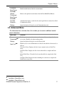
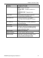
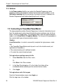
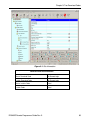
6.20 Zone Status/Trouble
This table is applicable to the PowerG models.
The Zone Status/Trouble screen displays diagnostic information for all zones that
are set up, equipped, and monitored on the premises. A Yes indication alerts that a
condition exists that needs checking. A No indication means that the condition is
normal.
∗ Available in PowerMaster models only
DE5450S Remote Programmer Guide Rev. 9
45
Chapter 6: Data Details Tables
Figure 6-7: Status Diagnostics
Note: The Channel Lst. Msg. column displays the last channel on which data was
transmitted between the zone’s installed device and the control panel. When the
transmissions between the control panel and devices change channels, the
channel indication is displayed in various colors, such as the purple and yellow
indications in the above figure.
46
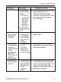
Condition
Description of Yes state
BYPASS
Bypassing of zone is enabled.
ALARM
Alarm is occurring in zone.
TROUBLE
Trouble detected in zone.
OPEN
Zone is open. For example, a room door was
opened.
TAMPER ALARM
Device tamper is occurring while system is an
Armed state.
TAMPER OPEN
Device tamper is occurring while system is either
in Armed or Disarmed state.
LOW BATTERY
Battery needs replacement or is not connected.
AC FAILURE
Electrical power is not supplied.
INACTIVE
Device is not communicating with control panel.
MODE
SET – System is armed.
DE5450S Remote Programmer Guide Rev. 9
Chapter 6: Data Details Tables
Condition
Description of Yes state
UNSET – System is disarmed.
PERIODIC TEST – Periodic test (walk test) in
process.
DIAGNOSTIC TEST – Diagnostic test in
process.
1-WAY ONLY
Communication between device and control
panel occurring in one direction only.
PRE-ENROLLED
Enrollment of the device is not complete –
device needs to be associated with the control
panel.
NOT UPDATED
Device configuration has not been updated yet
from the control panel.
HEAT OPEN
Extreme heat is occurring.
HEAT ALARM
Heat alarm is occurring, for example in extreme
heat. The alarm state ends only after disarming
and then rearming the system.
SMOKE OPEN
Smoke or fire is occurring.
SMOKE TROUBLE
The zone’s detector needs to be checked.
SMOKE ALARM
Smoke alarm is occurring, for example, a fire is
burning. The alarm state ends only after
disarming and then rearming the system.
DE5450S Remote Programmer Guide Rev. 9
47
Chapter 6: Data Details Tables
6.21 Panel Status/Trouble
This table is applicable to the PowerG models.
The Panel Status/Trouble screen displays diagnostic information that is uploaded
from the Control Panel.
A Yes indication alerts that a condition exists that needs checking. A No indication
means that the condition is normal.
48
Condition
Description
STATUS 1/
STATUS 2
Armed/Disarmed, Ready/Not Ready
LOW BATTERY
Control Panel’s battery needs replacement or
is not connected.
NOT ACTIVE
Control Panel is not transmitting.
FUSE TROUBLE
Fuse has shut the current circuit and will
reset automatically.
LINE FAILURE
Telephone line or network (such as GSM) is
disconnected.
COMMUNICATION
FAILURE
Communication failure between the control
panel and the monitoring station.
TAMPER OPEN
Control panel has been opened or tampered
with.
JAMMED
TROUBLE
Control panel transmissions are being
jammed.
TAMPER ALARM
Control panel has been opened or tampered
with. The alarm. The alarm state ends only
after disarming and then rearming the
system.
OTHERS
Other system faults.
PROTOCOL
VERSION
System’s communication protocol version.
DE5450S Remote Programmer Guide Rev. 9
Chapter 6: Data Details Tables
6.22 Event/History Log∗ ∗∗
The Event Log displays the different events that the control panel has detected,
together with their details. The Remote Programmer stores up to 100 events. This
table includes: event number; relevant zone or user number/code; relevant zone
name; type of event; date and time.
The History Log displays up to 1000 different events that the control panel has
detected and stored in a different folder.
6.23 Screen Saver∗∗∗
This function enables you to display any message on the control panel display
screen. The message may contain up to four rows of text (max. of 16 characters on
each row). To activate the screen saver, set the screen saver field at the panel
definition table to an option other than "off".
The screen saver will be displayed on the control panel between the defined
starting day and ending day and between the defined start time and end time of
each day.
∗
∗∗
∗∗∗
Available in PowerMax only: Performing Full Upload will automatically load the Event Log.
Available in PowerMax+ only:
• When communicating at the speed of 9600 bps (via serial or GSM digital communication), the Remote
Programmer loads all the data.
• When communicating at the speed of 300 bps (via PSTN or GSM analog communication), you need to perform
Upload Table to load the data.
Available in PowerMax+ only:
DE5450S Remote Programmer Guide Rev. 9
49
Chapter 7: Connecting to the Control Panel
Chapter 7: Connecting to the Control Panel
Connecting to the PowerMax/PowerMaster control panel enables the Remote
Programmer to transfer information to and from the control panel. The control
panel can be connected by remote connection (via telephone modem), used when
the operator specifies the parameters off-site, or by local connection (via direct
cable), used when the operator specifies the parameters on-site.
Once connected, it is possible to perform a number of operations, for example,
uploading site parameters, downloading site parameters or changing system date
and time.
7.1 Defining Communication Settings
The Communications dialog box enables you to determine the communication
settings by which the Remote Programmer and the control panel will communicate.
From the Communications menu, select Settings.
Figure 7-6: Options - Telephone Modem Communications Mode
Note: Whenever the Remote Programmer is connected, the Communications tab
becomes disabled.
50
DE5450S Remote Programmer Guide Rev. 9
Chapter 7: Connecting to the Control Panel
7.1.1 Local Connection (Serial Port)
Local connection is used when the Remote Programmer is within direct cable
connection distance from the PowerMax/PowerMaster control panel. When using
Local Connection, a modem is not needed.
1.
From the Communications mode drop-down list, select Serial Port. The
serial port parameters are displayed as follows:
• The Comm port field becomes enabled.
• The Baud rate field displays 9600, this being the baud rate used for
serial connection.
• The Parity and the Stop bits fields do not change.
Figure 7-2: Communications Mode - Serial Port
2.
Change the Comm port field as necessary.
3.
Auto-Detection Option: Check the Auto detect PowerMax when
program starts checkbox, so that when starting the program, the system
will automatically search for the control panel connected to the
communication port.
Note: The auto-detection option can also be activated by selecting
Port Auto Detection from the Communications menu or by
checking the relevant checkbox in the New Site dialog box.
4.
Click OK.
Note: When the auto detection procedure is initiated, either when
starting the program or when choosing this option in the
Communication menu or New Site dialog box, the following screen
will appear, showing you the names of the ports being scanned.
Figure 7-3: Progress Bar
DE5450S Remote Programmer Guide Rev. 9
51
Chapter 7: Connecting to the Control Panel
7.1.2 Remote Connection (Telephone Modem)
This is applicable when the Remote Programmer is off-site and the
PowerMax/PowerMaster control panel on-site is connected to Remote Programmer
by a telephone modem.
1.
From the Communications mode drop-down list, select one of the
following communication options:
Modem Type
Description
PSTN direct
Dials to the control panel by the PSTN line at a baud rate of 300.
PSTN callback
Dials to the control panel by the PSTN line at a baud rate of 300.
The control panel calls back.
GSM analog
direct
Dials the GSM unit of the control panel by analog
communication at a baud rate of 300.
GSM digital direct
Dials the GSM unit of the control panel by digital communication
at a baud rate of 9600.
GSM analog callback
Dials the GSM unit of the control panel by analog
communication at a baud rate of 300. The control panel calls
back at a baud rate of 9600.
GSM DTMF callback
This form of communication is used when transmission quality is poor.
DTMF signals instruct the panel to call back by digital communication
at a baud rate of 9600, using a Sony Ericsson Modem GM29
(mandatory).
GSM digital callback
Dials the GSM unit of the control panel at a baud rate of 9600. The
control panel calls back at a baud rate of 9600.
GSM communication enables the user to initiate both analog and digital
communication, as follows:
• Analog: Establishes connection to the control panel as in PSTN
communication. It provides a baud rate speed of 300 and performs full
download/upload in ten minutes.
• Digital: Provides higher quality and speedier connection to the control
panel at a baud rate speed of 9600. It performs full download/upload in one
minute. This type of connection is more reliable since it performs a
checksum (an error-detection scheme) on transmitted messages.
Although some networks use analog communication with satisfaction,
in other networks the quality of this type of communication may be
poor, which means that, in this case, performing uploading is almost
impossible via analog communication.
This problem can be overcome by using one of the two following
methods of using digital communication:
52
DE5450S Remote Programmer Guide Rev. 9
Chapter 7: Connecting to the Control Panel
i) The user needs to obtain a digital number for the GSM unit. The
Remote Programmer is then able to connect to the GSM unit via
digital communication (at a baud rate speed of 9600).
ii) DTMF callback connection uses a special GSM modem (Sony
Ericsson Modem GM29) which uses a digital number.
The Remote Programmer dials the GSM unit via analog
communication, but, instead of sending data it uses DTMF tones. The
Remote Programmer sends the download code (numeric, 0-9) and the
phone number (consisting of the Sony Ericsson Modem digital
number). After disconnection, the GSM unit calls back the Sony
Ericsson Modem (via digital communication at 9600 baud rate).
• The Comm port field becomes disabled and the field value is the
communications port where the modem is connected.
• The Baud rate field displays 300 (analog communication) or 9600 (digital
communication), the baud rate used for telephone modem connection.
• The Parity and the Stop bits fields do not change.
Figure 7-4: Options - Telephone Modem Communications Mode
2.
In the Telephone Modem section of the dialog box, select from the
Modem drop-down list, the modem to use for connecting to the control
panel.
DE5450S Remote Programmer Guide Rev. 9
53
Chapter 7: Connecting to the Control Panel
3.
Click Settings to display the Modem Settings dialog box, and define the
dialing and modem parameters.
Figure 7-5: Modem Settings
4.
Select Tone or Pulse as appropriate for the dialing mode.
5.
To connect to the control panel’s modem, the local software initiates the
dialing process. This process includes a number of steps:
Step 1: Dialing.
Step 2: Waiting 2-4 rings (The dialing process ends if connection is
made).
Step 3: Hanging up.
Step 4: Waiting a number of seconds before trying again.
Step 5: Beginning the dialing process again.
The Try to connect field defines the number of times the dialing
process should be initiated (steps 1-4). The Wait for 2-4 rings
during field defines the time allocated for the two to four telephone
rings (step 2). This time needs to be defined as different telephone
systems/modems take different amounts of time to carry out the
rings.
54
DE5450S Remote Programmer Guide Rev. 9
Chapter 7: Connecting to the Control Panel
The time entered into the Wait for Connection field should be no less
than the time entered in the Wait for 2-4 rings during field. The Wait for
Connection field defines the time (in seconds) it takes to dial to the
control panel, for the control panel to answer, and for the control panel
modem and the PC to establish connection.
Tip: If you are not sure of the time to enter in the Wait for 2-4 rings
during and Wait for Connection fields, enter a high number (i.e. 100
seconds), initiate connection as detailed in Connecting by Remote
Connection in Chapter 7. Time on your watch the number of seconds
your modem takes for 2 rings and then click Hang Up. Enter the number
of seconds entered in the Wait for 2-4 rings during field and Wait for
Connection fields.
6.
Check the Use only additional initialization commands checkbox to cancel
the two other options. The Ignore carrier detection and the Wait for dial tone
before dialing checkboxes initiate additional initialization commands to be
sent by the system.
7.
Make sure that the string of characters in the Additional initialization
commands is correct for the selected modem.
If not, click Select from recommended list; the Recommended
Modem Initialization Strings screen appears.
Figure 7-6: Recommended Modem Initialization Strings
8.
Select the correct initialization string, then click OK; the selected string
will appear in the Additional initialization commands edit box.
9.
Click OK; the Modem Settings dialog box closes and the Communication
dialog box appears.
10.
Click OK.
DE5450S Remote Programmer Guide Rev. 9
55
Chapter 7: Connecting to the Control Panel
7.1.3 Callback
In the Phone number field the user enters the Remote Programmer return
telephone number (the telephone number that connects to the modem). In the
Wait before sending field, the user enters the amount of time (in seconds) the
Remote Programmer waits before identifying the call as failed.
Figure 7-7: Callback Phone Number String
7.2 Connecting to PowerMax/PowerMaster
The login procedure enables Remote Programmer to transfer information to and
from the control panel and can be initiated either when creating a new site file or
when a site file is already open. This procedure differs when the communications
mode is set to Serial Port or Telephone Modem. The first part of the procedure is
the same for both types of communication modes:
Caution:
Local Connection - In order to successfully complete the login process, check
that:
• The PowerMax/PowerMaster control panel is set to the Installer mode (not
applicable to PowerMax+).
• The communication port is defined correctly.
• You enter the correct download code.
To Login when creating a new site file
1.
Select New Site from the Sites menu,
Or
Click New in the Sites window.
2.
In the New Site dialog box, fill in the fields (the fields will be
enabled/disabled according to the communication mode.).
3.
Click Login.
To Login when a site file is open
From the Communications menu select Login, or
Click the Login icon in the toolbar.
56
DE5450S Remote Programmer Guide Rev. 9
Chapter 7: Connecting to the Control Panel
Connecting by Local Connection (Serial Port)
After clicking Login, the communication icons in the status bar will become green,
and the Download and Upload icons in the toolbar become enabled and you have
successfully logged in.
Connecting by Remote Connection
(Telephone Modem/GSM/Callback)
When connecting by telephone modem, after clicking Login, the Modem dial up
dialog box appears.
Figure 7-8: Modem Dial Up...
Device displays the modem specified in the Communications dialog box.
1.
In the Phone number edit box, type the telephone number to which the
control panel is connected.
2.
Click the drop-down arrow to select a different communication mode.
3.
Click Connect. The system begins the login process.
4.
To interrupt the dialing process, click Hang Up; the system switches to
the 'wait 12 seconds' mode.
The Status indicates the current state of the connection process.
5.
Click Cancel to halt the connection process and return to the main
window.
DE5450S Remote Programmer Guide Rev. 9
57
Chapter 7: Connecting to the Control Panel
7.3 Online Operations
While connected to the PowerMax/PowerMaster control panel, you can perform the
following operations:
•
Check if the detectors in the various zones are enrolled and communicating
with the control panel.
•
Transfer information between the Remote Programmer and the control
panel by uploading or downloading either all site parameters or a specific
table.
•
Update the system date and time.
To check if a zone (detector) is enrolled and communicating with the
control panel
1.
In the List of Tables panel, go to Installer Settings>Definition>Zone
and select the relevant detector type.
2.
Click on the relevant zone number. A table representing the
selecting zone opens.
3.
Check if the detector’s LED blinks. If the LED blinks,
communication between the detector and the control panel is
working normally.
4.
To end the test and close the table, click OK or Cancel.
To Download or Upload All Site Parameters
Note: If you are interested in preserving changes already made in the control
panel, it is recommended to first upload all parameters, make necessary changes
and then download.
From the Communications menu, select Download or Upload,
Or
Click the appropriate icon on the toolbar.
The system begins to transfer data between the control panel and the Remote
Programmer. The wording on the message box changes according to whether the
transfer is upload or download.
58
DE5450S Remote Programmer Guide Rev. 9
Chapter 7: Connecting to the Control Panel
Figure 7-9: Uploading/Downloading Progress Bar Screen
At any point during the transfer, click Cancel to halt the procedure.
When the transfer is complete, a message box appears to confirm successful
completion.
Note: In PowerMax+, this process uploads all parameters except for the Event
Log. To upload the Event Log follow the To Upload a Specific Table procedure.
To Download or Upload a Specific Table
Note: Uploading a specific table is available in PowerMax+ only.
1.
Select a table by clicking on a table name in the List of Tables area, or by
clicking a table tab at the bottom of the screen.
2.
From the Communications menu, select Download Table or Upload
Table.
Note: Select the Data tab in Options, to determine whether changes will be
downloaded immediately, as they are made, or only when the download command
is chosen.
To Update System Time & Date
1.
From the Communications menu, select Change System Time & Date;
the Change system time & date dialog box appears.
Figure 7-10: System Time & Date Window
2.
In the Current date edit box, type the date. Use the format according to
the current date settings.
DE5450S Remote Programmer Guide Rev. 9
59
Chapter 7: Connecting to the Control Panel
3.
In the Current time edit box, type the time. Use either the 12 or 24 hour
clock format according to the current time settings.
4.
Click Send; Remote Programmer saves the modified date and time, and
updates the Control Panel.
To Update Customized Zone/Sensor Names
1.
From the Communications menu, select Customize Zone/Sensor
Names; the Customize Zone/Sensor Names dialog box appears.
Figure 7-11: Customize Zone/Sensor Names Window
2.
In the Current name list, select the name you want to change.
3.
In the New Name edit box, type the new name (15 characters max.).
4.
Click Send to update the Remote Programmer,
Or
Click Exit to exit the program.
Note: To see the customized zone after login, upload Customize Zone/Sensor Names.
7.4 Disconnecting from the PowerMax/PowerMaster
From the Communications menu, select Logout,
Or
Click the Logout icon
60
on the toolbar.
DE5450S Remote Programmer Guide Rev. 9
Chapter 8: Data
Chapter 8: Data
The data tab is used to define specific upload/download settings to facilitate data
transfer.
8.1 Defining Data Settings
The Data dialog box enables you to customize specific data settings in the
upload/download process.
From the View menu, select Options, then click on the Data tab; the Data dialog
box appears.
Applies only
to
PowerMax+
Figure 8-1: Options – Data Tab (PowerG Version)
Note: The contents of the Data dialog box may vary for each control panel
version.
DE5450S Remote Programmer Guide Rev. 9
61
Chapter 8: Data
1.
Check the Send updated data immediately field, to automatically update
changed settings from the Remote Programmer to the control panel.
Note: If the above field is not checked, the control panel will only be
updated when performing download table or full download.
2.
In the Delay after acknowledge during download field, enter a time
value (in milliseconds) for a delay in sending commands. This field
should be used when problems in communication is experienced.
3.
In the Download Code field, if a value (four hexadecimal digits) is
entered, the Remote Programmer uses this value instead of the value in
the site information field when performing login.
Note: If no value is entered in this field, then login is performed using the
download code in the site information table.
Note: For additional use of the download code see Chapter 9: Two
Download codes.
8.2 Using Customized Full Upload/Download Data
Note: The following section applies to PowerMax+ only.
This feature enables selecting only specific data to be uploaded/downloaded in
connection with the control panel. This saves significant time in
uploading/downloading data.
1.
Check the Enable customizing Full Upload/Download Data field, to
enable uploading/downloading of customized settings.
2.
Mark the relevant check boxes to specify the data to be uploaded to the
control panel.
Attention: Use the exact same customized fields for both uploading and
downloading in order to prevent inconsistency in the data.
Note: Click the Next/Prev buttons to see all the available fields.
Note: When X-10 Device Settings and PGM are selected, the scheduler
becomes functional (see chapter 6, for further details).∗
3.
Click OK; the Remote Programmer submits to memory the updated data.
Pressing full upload/download updates the control panel with the new
table settings.
Note: The regular full upload/download does not include a log file, the X-10
scheduler or the PGM scheduler.∗∗
∗ Available in PowerMax+ only
∗ ∗ Available in PowerMax+ only
62
DE5450S Remote Programmer Guide Rev. 9
Chapter 9: Two Download Codes
Chapter 9: Two Download Codes
This document explains the use of two download login codes - located in the
control panel (for further details, see PowerMax/PowerMaster User Guide) - used
for the two types of access codes, as follows:
• Master Installer – used to gain access to all the data in the control panel
(usually used by the central station).
• Installer – used to gain access to all the data in the control panel except for
central station data.
9.1 How It Works
Although Installers and Master Installers use the same software, access levels are
determined by the PowerMax/PowerMaster control panel.
There are two Download code types, as follows:
• Master Download code
• Installer Download code
When performing login using the download codes, the control panel will check the
download code to verify whether it is a Master download code or an Installer
download code.
In the event that the two download codes are identical, the control panel will
respond using the lower privilege (in this case the Installer privilege).
If the control panel responds with the Master privilege, the software is assigned
master privilege and will display all the fields.
If the control panel responds with the Installer privilege, then the software is
assigned Installer privilege and will hide all the central station data.
9.2 Operation
Master Installer First Time Login
When performing login for the first time, the Master installer will enter the Master
Installer download code.
Regular Login
If the PowerMax/PowerMaster control panel accepts this code as a Master
code, the Remote Programmer will assign a Master privilege, and from then
onward the software will be able to use the Master privilege allowing full
access at any time to all the fields (online and offline).
Note: Each time a user opens either an existing or new site he will be able to
view all the data.
DE5450S Remote Programmer Guide Rev. 9
63
Chapter 9: Two Download Codes
Installer
The installer enters the Installer download code and is assigned an Installer
privilege.
Special cases
A. Master and Installer as the same Download Code:
The PowerMax/PowerMaster control panel always confirms whether the download
code is Master or Installer. In the event that the Master and Installer code are
identical, the Remote Programmer will assign an Installer privilege.
To regain Master privilege
1.
Log into the Remote Programmer.
2.
Modify the Installer download code, then perform logout.
3.
Login using the Master installer download code, (click Options -> data tab,
then insert the download code in the Edit box). Since there are now two
different download codes in the control panel, the panel will return the Master
privilege.
4.
Modify the required data.
5.
Before performing logout, modify the Installer download code to its original.
You can either modify the Master Download code or leave it as it is.
6.
Save the data.
B. The Installer deciphered the Master Download code, what should I do?
If you use the same Master download code for all the panels and the installer
cracked the download code, then its software is assigned a Master Privilege. The
central station can offer protection in this type of situation by modifying all the
Master download codes. When the installer will try to perform login with the old
master download code, it will be rejected. The installer will be obliged to use his
(Installer) download code instead, which will result in the PowerMax/PowerMaster
control panel advising the software to use Installer privilege and from then onward
the software will operate in Installer privilege.
64
DE5450S Remote Programmer Guide Rev. 9
Chapter 9: Two Download Codes
Figure 9-1: Site Information
Download Code Site Information
Master Download Code
For Remote login
Installer Download Code
For Remote login
Master Installer Code
Panel
Installer Code
Panel
DE5450S Remote Programmer Guide Rev. 9
65
Chapter 10: Reports
Chapter 10: Reports
After you have created a site, you can generate a printable report of the site data.
To generate a report, first define the information to include in the report, preview
the report and then print it.
10.1 Defining and Generating a Report
Each Remote Programmer account comprises of 12 tables. You can generate a
report including information about some or all of these details. After you specify the
required details, Remote Programmer will generate the report.
To Define and Generate a Report
1.
From the View menu, select Options, or
Click the Options button on the toolbar; the Options dialog box
appears.
2.
Click the Reports tab; the Reports dialog box appears.
Figure 10-1: Options – Reports
Note: The contents of the Options dialog box may vary for each control
panel version.
66
DE5450S Remote Programmer Guide Rev. 9
Chapter 10: Reports
Mark the check boxes to specify the information to include in the Report.
3.
Click Apply; the tables to include in the report are selected, and the
Reports dialog box remains on the screen for further perusal and
selection.
4.
Click OK; Remote Programmer generates the report according to your
specifications.
10.2 Viewing a Report
Remote Programmer enables you to view reports before you print them. This
enables you to check that you have included all the necessary information in the
report.
To View a Report
From the Sites menu, select Print Preview.
Remote Programmer displays the report of the site on the screen as you have
specified for printing in the Options dialog box. This enables you to view the
different details of the report before you print it.
Note: Every report automatically includes details from the Client Description
screen.
The Print Preview toolbar enables you to do the following:
Print
Prints the report from the Print Preview screen.
Next
Page
Displays the following page of the report.
Prev Page
Displays the previous page of the report.
One Page
Displays one page of the report on the screen.
Two Page
Displays two pages of the report on the screen.
Zoom in
Increases the size of the report as it appears on the
screen. There are three possible view sizes available.
Zoom out
Decreases the size of the report as it appears on the
screen.
Close
Closes the Print Preview screen, and displays the main
Remote Programmer screen.
DE5450S Remote Programmer Guide Rev. 9
67
Chapter 10: Reports
10.3 Printing a Report
You can change the print setup for a report. This enables you to determine the
following:
·
The printer to print the report.
·
The paper size on which to print.
·
The source from which the printer should take paper.
·
The orientation of the paper.
To Determine the Print Setup
1.
From the Sites menu, select Print Setup; the Print Setup dialog box
appears.
2.
Specify the printer to where the report will be printed.
3.
Specify the paper size of the paper on which the report will be printed.
4.
Specify the paper source.
5.
Specify the orientation of the paper.
6.
Click OK.
To Print a Report
1.
From the Sites menu, select Print; Remote Programmer displays the
Print screen or click the Reports button on the toolbar.
Figure 10-7: Print Dialog Box
68
DE5450S Remote Programmer Guide Rev. 9
Chapter 10: Reports
This screen enables you to do the following:
•
•
•
Select the printer to print the report.
Determine the print range.
Determine the number of copies of the report, and whether or not they
should be collated.
2. Make the appropriate changes, then click OK; Remote Programmer prints
the report.
DE5450S Remote Programmer Guide Rev. 9
69
Chapter 11: Display (Screen Appearance)
Chapter 11: Display (Screen Appearance)
Any changes to the appearance of the Site screens are made in the Display tab of
the Options dialog box.
Figure 11-1: Options - Display Tab
11.1 Changing the Color
The colors of the Table Details are defined according to the following settings:
70
•
Table zebra color: Defines the color of every other line in each table. This
makes it easier for the user to follow the horizontal lines in the table.
•
Table disabled option color: Disabled tables appear in the selected shade.
•
Table normal option color: The color of the text as you type it.
•
Background color: The background color of the tables list and the sites list.
DE5450S Remote Programmer Guide Rev. 9
Chapter 11: Display (Screen Appearance)
To Change the Tables Color
1. From the View menu, select Options; the Options dialog box appears. By
default, the display tab is active.
2.
Click on the block of Tables zebra color; the color palette appears.
3.
Select a color, then click OK.
4.
Restart Remote Programmer.
11.2 Column Alignment
Remote Programmer defines the Table Details column alignment according to
one of the following settings: The Tables Column Alignment determines the width
of the table columns on the screen.
•
No auto alignment: All columns in the tables are the same width, regardless of
their contents.
•
Right justified: The columns in the table are all widened in order to cover the
entire screen.
•
Last column stretched: The last column in the table reaches the right side
of the screen, however wide the contents of the column.
•
Additional column: An additional column is added to the tables that are too
narrow to fill the screen. The extra column is the width of the empty space
between the last column of the table, and the right side of the screen.
To Change the Tables Column Alignment
Click the column alignment drop-down arrow, then select an option from the list.
Note: All changes to column alignment will become effective only after
performing restart of the Remote Programmer.
11.3 User Interface Language
Remote Programmer provides you with the possibility to change the language
used in the software interface.
To Change the User Interface Language
1. Click the Language User Interface language drop-down arrow, then select
a language from the list.
2.
Restart Remote Programmer.
DE5450S Remote Programmer Guide Rev. 9
71
Chapter 11: Display (Screen Appearance)
11.4 File Naming
This section provides you with the option for making compulsory the inclusion of
the account number in the file name.
To Enable the Account Number in the File Name Feature
72
1.
In the File Naming section; check the File name must include the
Account Number check box.
2.
Click OK.
DE5450S Remote Programmer Guide Rev. 9
Chapter 12: Troubleshooting
Chapter 12: Troubleshooting
PROBLEM
A. The Remote
Programmer
doesn't identify
the modem
DIAGNOSIS
A1. Your modem
might be OFF or
loosely
connected.
A2. You may have a
COM\IRQ
conflict.
B. Failure to comB1. You may have a
municate with the
conflict with the
control panel via
definitions in the
the modem.
communication
mode window.
B2. Your modem is
set to work at a
high baud rate.
B3. The modem type
is different from
the type
displayed in the
OPTIONS menu /
Communications
tab.
B4. The initialization
string is the
wrong one for the
modem in use.
DE5450S Remote Programmer Guide Rev. 9
POSSIBLE SOLUTION
A1. Make sure the modem is turned ON. A
power switch is available on any
external modem. The light on the front
panel should illuminate.
Note: An internal modem is powered
up when the computer is turned on.
Check whether the cable connectors are
fitted securely to their respective ports:
• The line connector in case of an
internal modem
• The line and RS-232 connectors in
case of an external modem.
A2. Check whether you have the correct
Com port and IRQ settings in your
software and/or in the Windows Control
Panel. Also verify that there are no
conflicts with other devices.
B1. Make sure you selected the Telephone
Modem option in the communication
mode window. Also verify that the
correct modem and INIT string are
specified.
B2. You need to set the baud rate to 300
bps
B3. Check that the correct modem type has
been selected.
B4. Select the correct string from the list of
Recommended Initialization Strings.
73
Chapter 12: Troubleshooting
PROBLEM
DIAGNOSIS
POSSIBLE SOLUTION
B. Failure to comB5. Modem is not
B5. Make sure that the modem is
municate with the
properly installed
recognized by Windows.
control panel via
in operating
If not, click Start → Setting → Control
the modem.
system
Panel. Double click the Modems icon
(cont.)
(Windows).
and follow the instructions on the
displayed Install New Modem window.
C. PC fails to
communicate
with the control
panel via the
Serial Port.
D. You can not log
into the
PowerMax/
PowerMaster.
74
C1. The RS-232
cable is
disconnected
from the Com
Port of your PC.
C2. The
PowerMax/Power
Master is not set
to the installer
mode.
C3. You may have a
definition conflict
in the OPTIONS
menu/
Communications
settings
C4. Your serial port is
defined to work
with high or low
baud rate.
C5. You may have a
COM Conflict.
D1. The Download
code is not
defined in the
download code
field.
C1. Verify proper connection of the RS-232
cable.
C2. Set the control panel to the installer
mode.
C3. Make sure that the Serial Port option is
currently selected.
C4. Make sure 9600 bps option is currently
selected in the OPTIONS menu /
Communications.
C5. Verify that the correct Com Port is
specified in the OPTIONS menu /
Communications
D1. Make sure you entered the correct
code into the Download field.
DE5450S Remote Programmer Guide Rev. 9
Chapter 12: Troubleshooting
PROBLEM
DIAGNOSIS
D2. Control panel
doesn't allow you
to login.
This is due to:
a) The system
being in Away
state and the
control panel is
set to allow
upload only at
Disarm state.
POSSIBLE SOLUTION
D2. a) Disarm control panel, then change
upload setting to Any Time.
b) Wait until the Exit/Entry state
terminates and the control panel enters
a valid state (Disarm/Arm/Home).
Then, login again.
b) The system
being in Exit/Entry
state.
E. The program
E1. You may have
E1. Restart your computer and run the
doesn’t behave
failed to restart
program again.
normally after
your computer
installation.
when prompted
to do so at the
end of
installation.
F. After installing
F1. After performing F1 Make connection to the PowerMax
the First
the software you
/PowerMaster control panel using the
see only the
Installation
Master download code.
Installer code and
software, the
software gains
Installer
download code
Installer Privilege.
but not the
Master code and
the Master
download code.
G. I do not have
G1. Authorization for G1. Perhaps login was performed using
Master Privilege
using the Master
the Installer Code. Another possible
anymore.
code and Master
cause is that the Installer Code is the
download code
same as the Master code. See
may be
Chapter 9, which provides details for
temporarily
dealing with the problem.
denied.
DE5450S Remote Programmer Guide Rev. 9
75
Appendix A: Language Settings
Appendix A: Language Settings
When using the Remote Programmer Software in Windows XP with a foreign
language interface, some characters may not appear correctly in the chosen
language. This may require changing the language settings.
Windows XP
1.
From Start>Settings>Control Panel double-click Regional and Language
Options. The Regional and Language Options dialog box appears.
Figure A-1: Regional and Language Options Window
76
2.
Click on the Advanced tab.
3.
Under Language for non-Unicode programs, click the drop-down list
and select the appropriate language.
4.
Click OK.
5.
Restart the computer.
DE5450S Remote Programmer Guide Rev. 9
Index
Index
1
H
1W Keypad Enrollment Screen, 39
Hardware/Software
requirements, 3
2
2W Keypad Enrollment Screen, 35,
41, 43
Help Menu, 12
A
Installation
general, 3
software, 3
Auto Detection, 51
C
Communication Settings, 50
Communications Definitions Screen,
29
I
Internal Siren/Strobe Screen, 30
K
Keyfob Enrollment Screen, 34
Communications Menu, 10
L
Connecting, 52
via serial port, 51, 57
Language, changing, 71, 72
Creating
site, 15
Local Connection, 51, 57
D
Disconnecting from PowerMax, 60
Download
all site parameters, 58
table, 59
E
Edit Menu, 9
Event Log Screen, 49
Exiting PowerMax Remote
Programmer, 8
External Voice Box Screen, 31
F
Formatting conventions, iii
DE5450S Remote Programmer Guide Rev. 9
List of Tables, 5
Local Data Transfer, 1
Login
failing to, 74
PowerMax, 56
M
Main Screen
general description, 4
list of tables, 5
menu bar, 5
status bar, 7
table data, 5
title bar, 5
toolbar, 6
Menu
communications, 10
edit, 9
help, 12
view, 10
77
Menu Bar, 5
Siren Enrollment Screen, 32
Modems
failing to communicate with, 73,
74
problems identifying, 73
settings, 54
Site Information Screen, 27
N
Sites
creating new, 15
displaying list of, 13
window, 13
Navigating PowerMax Remote
Programmer
arrow keys, 8
mouse, 8
Software
exiting, 8
Initiating, 4
installing, 3
requirements, 3
O
Status Bar, 7
Online Operations, 58
System Time & Date, changing, 59
P
T
Panel Definitions Screen, 29
Table Data, 5
Panel Status/Trouble Screen, 48
Table Details, 25
partitions enabled, 29
Table Names
1W keypad enrollment, 39
2W keypad enrollment, 35, 41,
43
communications definitions
screen, 29
event log screen, 49
external voice box, 31
internal siren/strobe, 30
keyfob enrollment screen, 34
panel definitions screen, 29
panel status/trouble screen, 48
PGM screen, 29
repeater enrollment, 37
siren enrollment, 32
site information, 27
user codes screen, 29
user settings screen, 28
X-10 device settings screen, 30,
31
X-10 general features screen, 30
zone definitions screen, 45
zone enrollment, 31
PGM Screen, 29
Print Setup, 68
R
Remote Connection, 52, 57
Repeater Enrollment Screen, 37
Reports, 67
generating, 61, 62, 63, 66
print setup, 68
printing, 68
viewing, 63, 67
Requirements
hardware/software, 3
S
Serial Port, 51, 57
Serial Ports
failing to communicate with, 74
78
DE5450S Remote Programmer Guide Rev. 9
Index
codes screen, 29
delete, 23
login as different, 23
settings screen, 28
zone status/trouble screen, 45
Telephone Modem, connecting via,
52, 57
Title Bar, 5
Tool Bar, 6
Troubleshooting, 73
login failure, 74
modem communication, 73, 74
modem identification, 73
serial port communication failure,
74
U
Upload
all site parameters, 58
table, 59
User
add, 23
change password, 23
DE5450S Remote Programmer Guide Rev. 9
V
View Menu, 10
X
X-10 Device Settings Screen, 30, 31
X-10 General Features Screen, 30
Z
Zone communication with control
panel, 58
Zone Definitions Screen, 45
Zone Enrollment Screen, 31
Zone Status/Trouble Screen, 45
79
2014 Tyco Security Products.
Remote Programmer Software User Guide, DE5450S (Rev.9, 10/2014)