1
Programming Instructions
This page is intentionally blank
HBPY-PR-1
2
This Manual
This manual describes how to program the Baxall Pyramid System using the menu
system. You should note, that the menu system is normally used for making
adjustments once the Pyramid System has been installed using the Pyramid
Installation Tool, PY-INS. Full information on the use of the Installation Tool is given
in the document, Installation Instructions, Pyramid Installation Tool and Utilities
Software.
If you are unfamiliar with the basic operation of the system, please refer to Manual
1a: Basic Operating Instructions, before you attempt to use the menu system.
It is assumed that your system hardware has already been installed correctly.
Warning
Important safety instructions are contained in section 1. These must be read
before using your Pyramid System.
This manual is divided into four sections:
Section 1, Important Safeguards, contains vital safety information, including the
Low Voltage Directive and EMC declaration, WARNINGS and CAUTIONS which
must be observed when installing the unit.
Section 2, The Pyramid System, provides a brief description of the system.
Section 3, Programming, describes the menu system, which allows access to the
system settings.
Section 4, Keyboard Engineering Settings, describes some settings that can be
made from the keyboard.
Section 5, Guidance Information, provides additional information for using the
programming facilities.
HBPY-PR-1
3
This page is intentionally left blank
HBPY-PR-1
4
Contents
1
IMPORTANT SAFEGUARDS
1.1
1.2
1.3
1.4
1.5
2
3
Safety
Damage Requiring Service
Safety and Electromagnetic Compatibility (EMC)
Manufacturer’s Declaration of Conformance
Year 2000 Conformity
8
9
9
10
10
10
THE PYRAMID SYSTEM
11
PROGRAMMING FACILITIES
14
3.1 Using The Menu System
3.2 Menu Formats
3.3 Navigating The Menu System
3.3.1
Soft Keys
3.3.2
Selecting Menu Options
3.3.3
Specifying Text
3.3.4
Specifying Numbers
3.3.5
As You Make Changes
3.4 The Available Menus
3.4.1
The Main Menu
3.4.2
Program Smartcard
3.4.3
3.4.4
3.4.5
3.4.6
HBPY-PR-1
14
16
17
17
18
18
19
19
20
20
21
Edit User Name
Priority
Set Privileges
Keyboard Privileges
Menu Privileges
Resource Code
Pin Number
Group ID
Program Smartcard
21
22
22
23
24
25
25
26
26
Set Sequence
27
Define Sequence
Video Source Range Menu
Adding a Video Source
Deleting a Video Source
Clear Sequence
Additional Note
27
28
29
29
30
30
Set Sync Sequence
31
Defining A Synchronised Sequence
Video Source Range Menu
Adding a Video Source
Deleting a Video Source
Clear Sync Sequence
Sync Sequence Dwell Time
Additional Note
31
32
33
33
33
34
34
Installer’s Details
Set Matrix
35
36
Set The Site ID
Set The Matrix Type
36
37
5
3.4.7
3.4.8
3.4.9
3.4.10
3.4.11
3.4.12
3.4.13
3.4.14
3.4.15
4
Set Time/Date Menu
38
Time
Date
39
40
Serial Port Config
41
Set VCR
Set MUX
Disable Driver
Serial Port Test
41
42
42
42
Alarm Config
43
Set Alarm To Response
Configure Response
Edit Alarm Caption
Reset:
Cam/Mon Pairs
Rx Presets
Serial Commands
Alarm Output Events
Priority
Store Alarm
Mode
Dedicated Alarm Monitor Mode
Display Stacking Mode
Camera Monitor Pairing
Activate Tamper
Alarm Input Module
Alarm Output Modules
Receivers
Edit Alarm Module Names
Alarm Input Module
Alarm Output Modules
44
46
48
48
50
51
53
56
57
59
59
60
60
60
61
62
63
64
65
65
66
Printer Log
Video Source Config
67
68
Video Source Title
Video Source Type
Camera
VCR, Mux, Other and None
Store Configuration
69
69
70
70
70
Caption Config
71
Select Monitor
Time Mode
Date Style
Time
Date
71
72
72
72
72
Edit White List
Display Installer
Engineering Info
73
73
74
KEYBOARD ENGINEERING SETTINGS
4.1
4.2
4.3
4.4
4.5
4.6
HBPY-PR-1
Self Binding
Store The Presets In Non-Volatile Memory
Store A Nominal Or An Average Auto-Iris Level
Turn On The OSD To The Selected Monitor
Turn Off The OSD To The Selected Monitor
Reset The Matrix To The Factory Settings
6
75
75
75
75
75
75
75
5
GENERAL GUIDANCE
5.1
5.2
76
Smart Cards
Site Configuration Records
76
77
APPENDIX A – SMART CARD RECORD
78
APPENDIX B – ALARM CONFIGURATION SHEET
79
APPENDIX C – RESPONSE CONFIGURATION SHEET
80
HBPY-PR-1
7
1 Important Safeguards
This product is exclusively for use in CCTV applications and has no other purpose.
Read and Retain the Instructions - All the safety and operating instructions should
be read before a unit is operated and should be retained for future reference.
Cleaning – Disconnect items of equipment before cleaning them. Do not use liquid
cleaners or aerosol cleaners. Use a damp cloth for cleaning.
Attachments - Do not use attachments not recommended by the product
manufacturer as they may cause hazards.
Water and Moisture - Do not use the items of equipment near water. For example,
near a bathtub, wash bowl, kitchen sink, or laundry tub, in a wet basement, near a
swimming pool, in an unprotected outdoor installation, or any area that is classified
as a wet location.
Accessories - Do not place items of equipment on unstable stands, tripods,
brackets, or mounts. A unit may fall, causing serious injury to a person and serious
damage to the unit. Any mounting of units should follow the manufacturer's
instructions, and should use a mounting accessory recommended by the
manufacturer.
Ventilation - Openings in enclosures, if any, are provided for ventilation to ensure
reliable operation of the unit and to protect it from overheating, these openings must
not be blocked or covered. Equipment should not be placed in a built-in installation
unless proper ventilation is provided. Do not place it directly on other hot equipment,
because this may increase its operating temperature.
Power Sources - Items of equipment should be operated only from the
recommended power sources.
Power-cord Protection - Power-supply cords should be routed so that they are not
likely to be walked on or pinched by items placed upon or against them. Pay
particular attention to cords at plugs, and the point where they exit from the
appliance.
Overloading - Do not overload outlets and extension cords as this can result in a risk
of fire or electric shock.
Object and Liquid Entry – This equipment must be protected from the ingress of
foreign materials. Never push objects of any kind into openings in the equipment as
they may touch dangerous voltage points or short-out parts that could result in a fire
or electric shock. Never spill liquid of any kind on the unit.
Servicing – There are no user-serviceable parts. If you remove the covers, ensure
that the power is off otherwise you may be exposed to dangerous voltages or other
hazards, including moving mechanical parts. Refer all servicing to qualified service
personnel.
HBPY-PR-1
8
Replacement Parts - When replacement parts are required, be sure the service
technician has used the replacement parts specified by the manufacturer.
Unauthorised substitutions may result in fire, electric shock or other hazards.
Safety Check - Upon completion of any service or repairs to a unit, ask the service
technician to perform safety checks to determine that the unit is in a proper operating
condition.
Surge Protection – All cables that may be affected by lightning, must be surge
protected.
1.1 Safety
If you have any problems, please contact Baxall Security Ltd.
WARNING
Competent, qualified and experienced personnel must install this equipment. The
installation must be in accordance with the country of installation’s National Wiring
Regulations
Refer to Baxall Security Ltd before using your system in a medical and/or intrinsically
safe application.
Do not exceed the voltage and temperature limits given in the specifications. Only
operate your system in a clean, dry, dust-free environment.
1.2 Damage Requiring Service
Refer your servicing to qualified service personnel under the following conditions:
•
•
•
•
•
•
•
When a power-supply cord or plug is damaged.
If liquid has been spilled, or objects have fallen into a unit.
If a unit has been exposed to rain or water.
If a unit does not operate normally by following the operating instructions.
If a unit has been dropped or the cabinet has been damaged.
When a unit exhibits a distinct change in performance.
If a unit has no power even when the power supply appears to operate correctly.
If this is the case then ask a service engineer to test the internal fuse.
HBPY-PR-1
9
1.3 Safety and Electromagnetic Compatibility (EMC)
Do not operate a unit outside the voltage and temperature limits given in the
specification.
This product is for use in general-purpose CCTV applications in a residential,
commercial or light industrial EMC environment. Refer to your agent before installing
or using the product in medical and/or intrinsically safe applications or in an industrial
EMC environment.
WARNING
This is a Class A product. In a domestic environment, this product may cause
radio interference, in which case, the user may be required to take adequate
measures.
The product must be installed in accordance with good installation practice, to enable
the product to function as intended and to prevent problems. Refer to your agent for
installation guidance.
Contact your agent to obtain a specification defining the acceptable levels of product
degradation with regard to EMC immunity.
1.4 Manufacturer’s Declaration of Conformance
The manufacturer declares that the product supplied with this document is compliant
with the essential protection requirements of the EMC directive 89/336 and the Low
Voltage Directive LVD 73/23 EEC. Conforming to the requirements of standards EN
55022 for emissions, IEC801 parts 2, 3 and 4 for immunity and BS415 superseded
by EN60950 for Electrical Equipment safety.
1.5 Year 2000 Conformity
This Pyramid System, which contains date and time-aware components, has been
tested in accordance with British Standards Institution, DISC PD2000-1, A Definition
of Year 2000 Conformity Requirements.
HBPY-PR-1
10
2 The Pyramid System
The Pyramid system is a large video management system, used to switch cameras
to monitors at your request. It also controls the movement of the cameras, controls
VCRs and multiplexers and processes alarms.
A typical Pyramid system may consist of many components, connected via a
network. These components may be viewed as building blocks, which enable the
customer’s current and future requirements to be met closely and economically. The
individual components are the Matrix, Keyboards, AC receivers, DC receivers, Alarm
input modules, Alarm output modules, Coaxial Telemetry Transmitters and Interfaces
to System 7000. Pyramid caters for single and multi-site applications, which can be
easily adapted and expanded to meet changing requirements. The system can have
up to 144 cameras, 32 monitors, 1024 alarm inputs and 1024 alarm outputs. It has
eight serial ports for connecting VCRs and multiplexers and a printer port for
connecting a log printer. A simple, single-site system is shown in Figure 1.
Cameras
Keyboard
VCR
Fn
F
FOCUS
IRIS
Monitors
RX
PTZ Camera
Echelon
Echelon
Alarm Output
Modules
RX
PTZ Camera
RX
Matrix
PTZ Camera
RX
PTZ Camera
Multiplexer
VCR
Printer
Figure 1 Simple, Single-site System
HBPY-PR-1
11
Alarm
Input
Modules
At the heart of the Pyramid system is the Matrix, PY-48M16. This enables any
camera to be displayed on any monitor (known as cross-point switching). It is this
device that stores the menu system and the configuration settings that you make on
the system.
The Pyramid system can be easily customised, precisely to your requirements, using
the menus provided. You can only access the menu system using a smart card which
has been programmed to give menu access privileges. In the same way, the menu
privileges can be restricted for different types of users, so that only the essential
menu facilities are provided.
The menu system is displayed on a selected monitor and is accessed using the
Pyramid keyboard. Using a combination of messages displayed on the keyboard’s
LCD (Liquid Crystal Display), keystrokes and the menus displayed on the monitor,
you can configure the system.
The main facilities provided in the menu system are the following.
Programming New Smart Cards
New smart cards can be programmed. In doing so, you specify the user name, the
user’s priority, the keyboard and menu privileges and the PIN. If required, you can
easily cancel the smart card.
Video Source Configuration
You can configure the system’s video sources. To do this, you specify what type
of source they are (e.g. camera – controllable or non-controllable, VCR or
multiplexer) and what textual title they have.
Defining Synchronised and Non-synchronised Sequences
You can specify up to 16 sequences, each with 16 cameras, and each camera
can have its own dwell time. In addition, you can define up to 16 synchronised
sequences, each of which can contain up to 16 cameras. Synchronised
sequences differ from normal sequences in that when several of them are set
running at the same time on different monitors, they all switch from camera to
camera at the same time, with the same dwell time.
Setting The Time And Date And Their Formats
You can specify, on a monitor by monitor basis, whether the time and/or date are
to be displayed. You can choose a 12hr or 24hr time display and a DDMMYY or
MMDDYY date format display.
Configuring Alarms
You have comprehensive control over what happens in the event of alarms. For
each of up to 1024 alarm inputs, you can allocate one of up to 1024 definable
“responses”. The responses determine what the system does and what the
operator sees. For each response, you can specify the alarm’s priority, caption
and whether the operator must intervene to remove it from the Active Alarm list.
Up to eight camera/monitor pairs can be displayed when the alarm event occurs.
Where cameras are controllable, up to eight can be sent to selected preset
positions. You can specify commands that will be issued to the connected devices
in the event of the alarm, for example, to control a VCR. Up to 3 alarm output
contacts from up to 1024 different outputs can be activated by the alarm.
HBPY-PR-1
12
Configuring Serial Ports
You can set up the serial ports for connection to multiplexers and VCR’s of
selectable types.
Selecting The Printer Output
You can select what information is to be logged to your system’s printer.
This manual tells you how to use the menu system facilities to make the changes that
you require.
HBPY-PR-1
13
3 Programming Facilities
This section describes the menu facilities provided for programming the Pyramid
System.
3.1 Using The Menu System
The Pyramid System has a comprehensive set of on-screen menus for configuring
the system.
To use the menu system, you must log on using your smart card. In the description
given below, it is assumed that you are using the Installer’s smart card, which
provides access to all of the menu facilities. If you are not using an Installer’s smart
card, you may not have access to all of the facilities. The keyboard layout is shown in
Figure 2.
Figure 2 Keyboard Layout
Before you have inserted your smart card, the keyboard displays:
Insert the Installer’s smart card into the left-hand side of the keyboard. When you do
this, the following keyboard message is displayed:
HBPY-PR-1
14
Type in the Installer’s PIN using the numeric key pad on the right-hand side of the
keyboard. When you have logged on, the following message is displayed:
Select the monitor which is to display the menu system by typing its number and
pressing the Monitor key in the FUNCTIONS area to the right of the keyboard (see
Figure 2).
Press the LIST up key p. The keyboard displays:
Press the Yes soft key to display the Pyramid System’s Main menu (see page 20) on
the selected monitor.
Note
You can only access the menu system immediately after you have logged on
using the smart card. If you have already selected a camera, you cannot access
the menu system unless you log on again to the system.
HBPY-PR-1
15
3.2 Menu Formats
In general, the menus have the following format:
Menu Number
0
8Option
Option Pointer
Option
Option
Option
Option
Option
Option
Option
Option
1
2
3
4
5
6
7
8
9
Options
00:33:34 01-08-98
Time
êê
More
Date
Figure 3 Menu Format
Menu Number
This helps you know where you are in the menu system. It is displayed as a series
of numbers, separated by fullstops, made up from the logical option numbers you
have selected to get to that menu, but excluding the menu number for the Main
menu (menu number 0). For example, if option 2 was selected in the main menu
and this displays another menu, this will have the Menu Number 2. If you select
the first option in Menu Number 2 and this displays another menu, this will have
the Menu Number 2.1 and so on.
Option Pointer
The option pointer 4 is provided to enable you to point to menu items that you
wish to select. You move the option pointer by using the up and down arrow keys
tu in the LIST area of the keyboard (see Figure 2).
Options
These are text descriptions of the selectable facilities provided in the menu.
More
This symbol is displayed if the menu contains more options than can be displayed
in a single screen. It is shown as êê at the bottom of the screen if there are
options you can move downwards to and éé at the top of the screen if there are
options that you can move upwards to. If the end options list is currently displayed,
the symbol is displayed as
.
Time and Date
Show the current date and time held in the system.
HBPY-PR-1
16
3.3 Navigating The Menu System
In general, the menus are lists of options that you can select. If you select the option,
depending on the menu in question, you may get another menu displayed or you
may need to type something on the keyboard.
3.3.1
Soft Keys
The keys underneath the LCD display on the keyboard are referred to as soft keys
(see Figure 2). These are used in conjunction with the menus displayed on the
monitor, to help you use the menu system. Depending upon where you are in the
menu system, they can have different functions allocated to them. The functions are
indicated on the bottom line of the LCD.
The primary soft key functions are ABORT, BACK and ENTER for soft keys 1,2 and
3 respectively. These do the following:
ABORT
This ends the Change System Setup Session. The changes that you have made
to the setup are retained. When you have ABORTed the session, the keyboard
LCD shows the following message:
Note
If you have ABORTed a session, and you have not selected a camera on the
keyboard, you can start a new Change System Setup Session without having to
log on again.
HBPY-PR-1
17
BACK
This takes you back to the previous menu, unless the main menu (Menu Number
0) is currently on display, in which case, BACK has no affect.
ENTER
This is used to select menu options.
3.3.2
Selecting Menu Options
In general, you select options from the menus by doing the following.
1) Move the option pointer 4 to the option that you require using the up and down
arrow keys tu in the LIST area of the keyboard (see Figure 2).
2) Press the ENTER soft key (soft key 3).
Every new session starts with the main menu (menu number 0). When you have
selected an option from the main menu, you usually get another menu displayed. In
this, you may be selecting other options that again may display a further menu. In
other cases, you will be typing in values, or selecting alternatives.
3.3.3
Specifying Text
Some of the menus that you will use require that you input items of text. For
example, you may need to specify a user name or a video source name. In general,
you select the item in the menu, and it starts flashing. At the same time, you are
presented with a message, displayed on the keyboard’s LCD display, which has the
following format:
RIGHT and END are the current functions of soft keys 1 and 3 respectively. These
operate in the following way:
Soft key
1
2
3
Name
RIGHT
END
Function
press once to move one character to the right
finish the text before the current character position and
show it in the monitor menu
You edit the User name in the following way:
1) To the right of the soft key text RIGHT in the keyboard display, is displayed the
first character of the Current text . To change it, use the up and down arrow
keys tu in the LIST area of the keyboard (see Figure 2). This will cycle
through the lower case alphabet and the characters + - : . = and space.
HBPY-PR-1
18
2) You can change from lower case to an upper case alphabet by pressing the
previous camera key
(at the bottom of the LIST area of the keyboard)
twice.
3) To change from an upper case alphabet to a lower case one, press the
once.
previous camera key
4) To insert a space, if you are currently using the lower case alphabet, press the
previous camera key once and press the up or down arrow key tu. If you are
in the uppercase alphabet, press the previous camera key twice and press the
up or down arrow key tu. If you have inserted a space in this way, pressing
the previous camera key once and pressing the up or down arrow key tuwill
select the upper case alphabet. If you press the previous camera twice and
press the up or down arrow keys tu, this selects the lower case alphabet.
5) As you select each character in the user name, press the RIGHT soft key to
move to the next character position.
6) When you have finished specifying the text, press the RIGHT soft key once
then press the END soft key. This will display the text in the menu.
3.3.4
Specifying Numbers
Some of the menus that you will use require that you input numerical items. For
example, you may need to specify a Priority or Pin number if you are programming a
smart card. In general, you select the item in the menu, and it starts flashing. At the
same time, you are presented with a message, displayed on the keyboard’s LCD
display, which has the following format:
RIGHT and END are the current functions of soft keys 1 and 3 respectively. These
operate in the following way:
Soft key
1
2
3
Name
RIGHT
END
Function
press once to move one character to the right
finish the number at the current character position and
show it in the monitor menu
To specify the number, type all the digits of the number on the numeric area of your
keypad and press the END soft key.
3.3.5
As You Make Changes
In general, the configuration changes that you make using the menus are stored in
the matrix in non-volatile memory as you make them. The exceptions to this are
when you use menus that contain store options e.g. store configuration and store
alarm. In these cases, the changes are not stored in the matrix until the store option
has been selected.
HBPY-PR-1
19
3.4 The Available Menus
In this section, the menus are shown in a simplified format without the time and date.
Where there are too many options to display at once on the screen and in practice,
you would scroll them to view them all, these are simply shown as a complete and
continuous list.
In the description, it is assumed that the Installer smart card is being used, and that
all of the facilities can be accessed. However, if you are using a different card, not all
the facilities will necessarily be available.
3.4.1
The Main Menu
The main menu is a list of the programmable options. The programmable options
provided are described in detail in the rest of section 3.4. You should read the
corresponding section in the manual before starting to program the options in the
menus.
The main menu has the following options:
0
8Program smartcard
Set sequence
Set sync sequence
Installer’s details
Set matrix
Set time/date menu
Serial port config
Alarm config
Printer logs
Video source config
Caption config
Edit white list
Display installer
Engineering Info
HBPY-PR-1
20
3.4.2
Program Smartcard
Access to the Pyramid system is controlled using smart cards. This option lets you
program those smart cards. In doing so, you specify the user name, the user’s
priority, the menu and keyboard privileges, the resource code, the PIN that must be
entered at log on and the group ID.
When you select this option, the Program smart card menu is displayed:
1
User name
4 Edit user name
Priority
0-255:--Set privileges
:--Resource code 0-255:--Pin number
:---Group ID
:--Program Smartcard
:---
Edit User Name
This option allows you to specify the user name for the card. This is displayed on the
keyboard LCD each time the card is inserted into the reader.
When you select Edit user name, the current user name at the top of the menu
flashes and the keyboard LCD displays a message similar to the following:
Edit the User name as described on page 18. When you have finished, it is displayed
at the top of the Program smart card menu.
Note
The user name that you specify for the smart card is added to the “white list” see
page 73.
HBPY-PR-1
21
Priority
This option enables you to allocate a priority to a user. The priority is used to resolve
operational conflicts. For example, if more than one user attempts to control the
same PTZ camera at the same time, the user with the highest priority gains control.
When you select Priority, the following keyboard message is displayed:
The priority must be a number in the range 0 to 255. The higher the number, the
higher is the priority. Input the priority as described on page 19.
Set Privileges
This option allows you to allocate to the user, access rights to the keyboard and
menu facilities.
When you select Set privileges, you get the Set privileges menu:
1.4
4Keyboard Privileges
Menu Privileges
HBPY-PR-1
22
Keyboard Privileges
Select Keyboard privileges, which displays the following menu:
1.4.1
4Select Cameras
Select Monitors
Select Sequence
Control Cameras
Control Multiplexers
Control VCR record
Control VCR stop
Control VCR playback
Menu Access
Self binding
Suspend priority
To specify the keyboard privileges, move the option pointer using the up and down
arrow keys tu to each privilege which is required, and press the ENTER soft
function key. As you select each item, a + character is inserted to the left of the
option’s text to show that it has been selected (that is, access has been granted).
When you have selected all of the privileges, press the BACK soft function key to
return to the Set Privileges menu.
Note
When the user of the smart card attempts to use a keyboard facility to which
access has not been granted, the keyboard LCD displays the following message:
HBPY-PR-1
23
Menu Privileges
Select Menu privileges in the Set privileges menu. If you did not select Menu
Access as a keyboard privilege (see above) the following menu is displayed:
1.4.2
4Set Menu Access Privilege
Press the ENTER soft key and the Keyboard privileges menu is displayed with the
option pointer positioned at the Menu Access option. Press the ENTER soft key to
select Menu Access and press the BACK soft key to display the Menu privileges
menu:
1.4.2
8Programming Smartcards
Setting sequences
Installer’s details
Set time and date
Serial Port config
Alarm config
Printer log config
Video source config
Caption config
Edit white list
To specify the menu privileges, move the option pointer using the up and down arrow
keys tu to each privilege which is required, and press the ENTER soft function key.
As you select each item, a + character is inserted to the left of the option’s text to
show that it has been selected (that is, access has been granted).
When you have selected the required privileges, press the BACK soft function key to
return to the Set Privileges menu.
HBPY-PR-1
24
Press the BACK soft key again to return to the Program smartcard menu. The Set
privileges field displays the text OK when the privileges have been set.
Note
When the smart card is used, only the menu options to which access has been
granted will be displayed, plus the Display installer and Engineering Info options.
If the user is to access to the menu system, access to Select Monitors in the
keyboard privileges must also be granted.
Resource Code
This item is reserved for future development and does not currently affect the
operation of the system. However, a number must be entered to enable the
programming of the smart card to be completed. When you select Resource code,
the following is displayed:
The Resource code must be a number in the range 0 to 255. Input the Resource
code as described on page 19.
Pin Number
This option allows you to specify the PIN (Personal Identification Number) that must
be entered each time the card is used to log on to the system.
When you select Pin number, the following is displayed:
It recommended, for security reasons, that the PIN should always be 4 digits. Input
the PIN as described on page 19. When you have finished, the Pin number field is
set to **** in the Program smartcard menu.
HBPY-PR-1
25
Group ID
This item is reserved for future development and does not currently affect the
operation of the system. However, a number must be entered to enable the
programming of the smart card to be completed. When you select Group ID, the
following is displayed:
Group ID must be a number in the range 0 to 255. Input the Group ID as described
on page 19.
Program Smartcard
When you have specified all of the options for the card, the text OK is displayed in
the Program Smartcard field. To record the options on a new card, select the
Program Smartcard option and press the ENTER soft key.
The following message is displayed on the keyboard:
Remove your smart card from the keyboard and insert the new one to be
programmed. When the LEDs flash, the process is complete and the following
message is displayed on the keyboard:
The user name is as you specified when programming the smartcard.
Note
Do not remove your smart card and reinsert it, unless you want to reprogram it
with the new card details.
It is recommended that details of each smart card are recorded, and kept in a
secure place for future reference. An example form is provided in Appendix A.
HBPY-PR-1
26
3.4.3
Set Sequence
This option lets you program camera sequences for the Pyramid System. You can
specify up to 16 sequences, each with 16 cameras. In doing so, you select a
sequence number, the sequence of cameras and the dwell time for each camera.
When you select this option, you get the Set sequence menu:
2
4Define sequence
Clear sequence
Define Sequence
Select the Define sequence option and the Sequence menu is displayed:
2.1
4Sequence
Sequence
Sequence
Sequence
Sequence
Sequence
Sequence
Sequence
Sequence
Sequence
Sequence
Sequence
Sequence
Sequence
Sequence
Sequence
HBPY-PR-1
1
2
3
4
5
6
7
8
9
10
11
12
13
14
15
16
27
Select the sequence that you wish to edit and you get the a display similar to the
following:
2.1.1
401:Camera
02:Camera
03:Camera
04:Camera
05:Camera
06:Camera
07:Camera
08:Camera
09:Camera
10:Camera
11:Camera
12:Camera
13:Camera
14:Camera
15:Camera
16:Camera
001
002
003
004
005
006
007
008
009
010
011
012
013
014
015
016
2
2
2
2
2
2
2
2
2
2
2
2
2
2
2
2
In this example, sequence 1 has already been defined and contains cameras 001 to
016 which respectively, have the selected dwell times of two seconds.
Video Source Range Menu
Select the sequence entry that you wish to edit and a Video source range menu
similar to the following is displayed:
2.1.1.1
4Video source
1-10
Video source 11-20
Video source 21-30
Video source 31-40
Video source 41-50
Delete video source
HBPY-PR-1
28
Adding a Video Source
Select the video source range that contains the required camera. For example, if you
want camera 003, choose Video source 1-10 and you get the range displayed:
2.1.1.1.1
4001:Camera
002:Camera
003:Camera
004:Camera
005:Camera
006:Camera
007:Camera
008:Camera
010:Camera
001
002
003
004
005
006
007
008
009
Select the Camera that is to be added to the sequence. This displays the Dwell Time
menu:
2.1.1.1.1.1
4
Enter dwell time
1 – 255
----
At the same time the keyboard displays:
The dwell time must be a number in the range 1 to 255. Input the dwell time as
described on page 19.
Deleting a Video Source
To delete a video source, select the item in the required sequence and select Delete
video source in the Video source range menu. The video source is deleted and the
sequence is displayed again.
HBPY-PR-1
29
Clear Sequence
To clear an entire sequence, select Clear sequence from the Set sequence menu.
This displays the Sequence menu:
2.2
4Sequence
Sequence
Sequence
Sequence
Sequence
Sequence
Sequence
Sequence
Sequence
Sequence
Sequence
Sequence
Sequence
Sequence
Sequence
Sequence
1
2
3
4
5
6
7
8
9
10
11
12
13
14
15
16
Select the sequence and press the ENTER soft key. The sequence is cleared (that
is, all of the video sources are removed from the sequence) and you are returned to
the Set sequence menu.
Additional Note
You can define up to 16 sequences and up to 16 synchronous sequences. When you
run them (see Manual 1a: Basic Instructions, Pyramid Systems), synchronous
sequences are selected by specifying numbers 17 to 32. Non-synchronous
sequences are selected by specifying numbers 1 to 16.
HBPY-PR-1
30
3.4.4
Set Sync Sequence
This option lets you define up to 16 synchronised sequences, each of which can
contain up to 16 cameras. Synchronised sequences differ from normal sequences in
that when several of them are set running at the same time on different monitors,
they all switch from camera to camera at the same time, and with the same dwell
time.
To set up synchronised sequences, select Set sync sequence from the main menu.
This displays the Set sync sequence menu:
3
4Define sync sequence
Clear sync sequence
Set sync sequence dwell
:Current dwell…6secs
In this example, the current dwell time for the synchronised sequences is set to 6
seconds.
Defining A Synchronised Sequence
Select Define sync sequence from the Set sync sequence menu. The Sync
sequence menu is displayed:
3.1
4Sync
Sync
Sync
Sync
Sync
Sync
Sync
Sync
Sync
Sync
Sync
Sync
Sync
Sync
Sync
Sync
HBPY-PR-1
sequence
sequence
sequence
sequence
sequence
sequence
sequence
sequence
sequence
sequence
sequence
sequence
sequence
sequence
sequence
sequence
1
2
3
4
5
6
7
8
9
10
11
12
13
14
15
16
31
Select the Sync sequence that you wish to edit and press the ENTER soft key. You
get the a display similar to the following:
3.1.1
401:Camera
02:Camera
03:Camera
04:Camera
05:Camera
06:Camera
07:Camera
08:Camera
09:Camera
10:Camera
11:Camera
12:Camera
13:Camera
14:Camera
15:Camera
16:Camera
001
002
003
004
005
006
007
008
009
010
011
012
013
014
015
016
In this example, sequence 1 has already been defined and contains cameras 001 to
016.
Video Source Range Menu
Select the Sync sequence entry that you wish to edit and you get a Video source
range menu similar to the following:
3.1.1.1
4Video source
1-10
Video source 11-20
Video source 21-30
Video source 31-40
Video source 41-50
Delete video source
HBPY-PR-1
32
Adding a Video Source
Select the video source range that contains the required camera. For example, if you
want camera 003, choose Video source 1-10 and you get the range displayed:
3.1.1.1.1
4001:Camera
002:Camera
003:Camera
004:Camera
005:Camera
006:Camera
007:Camera
008:Camera
009:Camera
010:Camera
001
002
003
004
005
006
007
008
009
010
Select the Camera that is to be added to the sync sequence and press the ENTER
soft key. This adds the camera to the sync sequence and displays the sync
sequence again.
Deleting a Video Source
To delete a video source select the camera in the required sync sequence and select
Delete video source in the Video source range menu. The video source is deleted
and the sync sequence is displayed again.
Clear Sync Sequence
To clear a Sync sequence select Clear sync sequence from the Set sync sequence
menu. This displays the Sync sequence menu:
3.1
4Sync
Sync
Sync
Sync
Sync
Sync
Sync
Sync
Sync
Sync
Sync
Sync
Sync
Sync
Sync
Sync
HBPY-PR-1
sequence
sequence
sequence
sequence
sequence
sequence
sequence
sequence
sequence
sequence
sequence
sequence
sequence
sequence
sequence
sequence
1
2
3
4
5
6
7
8
9
10
11
12
13
14
15
16
33
Select the Sync sequence and press the ENTER soft key. The sync sequence is
cleared and you are returned to the Set sync sequence menu.
Sync Sequence Dwell Time
To set the dwell time for your synchronised sequences, select Set sync sequence
dwell time from the Set sync sequence menu. This displays the following:
3.3
4
Enter dwell time
5 – 999
----
At the same time the keyboard displays:
The dwell time must be a number in the range 5 - 999. Input the dwell time as
described on page 19. The Set sync sequence menu is displayed with the new
dwell time shown.
Additional Note
You can define up to 16 sequences and up to 16 synchronous sequences. When you
run them (see Manual 1a: Basic Instructions, Pyramid Systems), synchronous
sequences are selected by specifying numbers 17 to 32. Non-synchronous
sequences are selected by specifying numbers 1 to 16.
HBPY-PR-1
34
3.4.5
Installer’s Details
This option allows you to specify the installer’s name and address. When you select
it, you get the Installer’s details menu:
4
4Enter Installer
Baxall Security Ltd
Castlehill
Bredbury Park Ind Est
Bredbury
Stockport
If the Installer’s details have been input already, the details are displayed. To edit a
line in the installer’s details, select the required line. The text in the line (e.g.
Bredbury), flashes and the keyboard LCD displays a message similar to the
following:
Edit the text as described on page 18.
When you have finished editing the Installer’s details, press the BACK soft key to
return to the main menu.
HBPY-PR-1
35
3.4.6
Set Matrix
This option enables you to set the Site ID, to set the matrix type as Master or Output
Expander, and for an output expander, to specify the master matrix which it expands
(its parent).
When you select this option, you get the Set matrix menu:
5
4Set Site ID. … . . 0
Set Matrix type… MASTER
Set The Site ID
Select the Set Site ID option from the Set matrix menu. The keyboard will display:
Specify the site ID number as up to five digits, see page 19.
Note
The site ID is used in systems that have networked multiple master matrices, to
enable the keyboard to access any one of those matrices.
HBPY-PR-1
36
Set The Matrix Type
Select the Set Matrix type option from the Set Matrix menu. The Set Matrix type
menu is displayed:
5.2
4Master
Output expander
For a Master matrix, select the Master option. You are returned to the Set Matrix
menu, with the Set Matrix type field set to MASTER.
For an output expander unit, select Output expander. You are returned to the Set
Matrix menu, with the Set Matrix type field set to O/P EXP. An additional Set Exp
parent option is displayed:
5
4Set Site ID. … . . 0
Set Matrix type… O/P EXP
Set Exp parent…….1
To specify the Expander’s parent, select the Set Exp parent option. The keyboard
displays:
Type in a number in the range 0 to 6, see page 19.
HBPY-PR-1
37
Note
You should take care not to set a Master Matrix to an Output expander in error. If
you do this, the next time you try to use the menu system, you will get a Monitor
not known message on the keyboard. If this happens, you must do one of two
things. Either:
1) Log on to the keyboard, select monitor 17 before you press the up arrow key in
the LIST area of the keyboard, and to use the menu system to set the matrix
back to MASTER. Next time you use the menu system, you select monitor 1
as usual.
Or
2) Reset the matrix to the default factory settings. To do this, type 251 and press
the function key Fn. Switch off the power to the matrix and switch the power on
again. As the matrix boots up, it will show a blue introduction screen with a
series of numbers and letters displayed in the top right corner. When it has
finished booting up, it will return to displaying video pictures. You can then log
on to the keyboard and use your menu system in the normal way again.
Caution
Resetting to the default factory settings means that any configuration information
that you have already specified will be lost.
3.4.7
Set Time/Date Menu
This option allows you to set the time and date. When you select this option, you get
the Time/Date Menu:
6
4Set Time
Set Date
HBPY-PR-1
38
Time
To set the time, select Set Time and the Time menu is displayed:
5.1 Time
Enter new time
hrs:mins:secs
12:56:23
**
OK
The asterisk characters ** enable you to select each part of the time (hours, minutes
and seconds) in turn so that you can change them. In the above example, the
asterisk characters are located under the hours part of the time. If you do not wish to
change the hours press the ENTER soft key and the asterisks move to the minutes
part of the time. If you do wish to change the hours, use the up and down arrow keys
tu in the LIST area of the keyboard (see Figure 2), then press the ENTER soft key.
Do this for each time field, and the asterisk characters will be located under OK. To
set the time at the specified value, press the ENTER soft key and you are returned to
the Set time/date menu. This will show the new time, which will be incremented by
the time it takes to display the menu.
Note
It takes a few seconds to specify all of the time fields. Therefore, you should
specify a time that is, say, 2 minutes in the future and ensure that the asterisk
characters ** are located under OK. Then, with reference to the clock that you are
using to set the time against, press the ENTER soft key as that clock shows the
time that you have specified.
HBPY-PR-1
39
Date
To set the date, select the Set Date option and you get the Date Menu:
5.2 Date
Enter new date
day-month-year
14-07-97
OK
**
The asterisk characters ** enable you to select each part of the date (day, month and
year) in turn so that you can change them. In the above example, the asterisk
characters are located under the day part of the date. If you do not wish to change
the days press the ENTER soft key and the asterisks move to the months part of the
date. If you do wish to change the days, use the up and down arrow keys tu in the
LIST area of the keyboard (see Figure 2), then press the ENTER soft key. Do this for
each date field, and the asterisk characters will be located under OK. To set the date
at the specified value, press the ENTER soft key and you are returned to the Set
time/date menu which will show the new date.
HBPY-PR-1
40
3.4.8
Serial Port Config
This option allows you to configure the system’s serial ports. You need to do this so
that the correct device driver is allocated to the port. When you select the option, you
get the Serial port config menu:
7
4P1: VCR1 :Mitsubishi
P2: VCR2 :Mitsubishi
P3: VCR3 :Mitsubishi
P4: VCR4 :Mitsubishi
P5: Mux1 :DM uniplex
P6: Mux2 :DM uniplex
P7: Mux3 :DM uniplex
P8: Mux4 :DM uniplex
Serial Port Test
5600L
5600L
5600L
5600L
To configure a port, select the port and press the ENTER soft key. The Select driver
menu is displayed:
7.1
4Set VCR
Set MUX
Disable driver
Set VCR
If the port is to be used for a VCR, select Set VCR. This displays the video options
menu:
7.1.1
4Mitsubishi 5600L
Mitsubishi 5600
JVC 925E
HBPY-PR-1
41
Set MUX
If the port is to be connected to a multiplexer, select Set MUX in the Select driver
menu. This displays the Multiplexers menu, which is similar to the following:
7.1.2
4DM Uniplex
ZMX-16
ZMX-9
ZMX-8
Kramplex
Select the option that you require and press the ENTER soft key to return to the
Select driver menu.
Disable Driver
If the port is not going to have a driver associated with it, select the Disable driver
option in the Select driver menu and press the ENTER soft key. The Serial port
config menu is displayed with the selected port field showing No device.
Note
There is no operational reason to disable a driver for a port if nothing is connected
to that port. However, if you do take the trouble to disable the drivers for unused
ports, the Serial port config menu can be used as a quick reference to see what
is currently connected to the system.
Serial Port Test
Note
This test is provided for use by qualified test/maintenance personnel only.
Loopback connectors must be inserted in the serial ports to perform the test.
Select the Test serial ports option in the Serial port config menu. While the test is
under way, the text Testing… is displayed. When the test is complete, a Serial Port
Test Results report is displayed for all the ports, which are shown as having passed
or failed.
To return to the Serial port config menu, press the ENTER or BACK soft key.
HBPY-PR-1
42
3.4.9
Alarm Config
The Pyramid system has very flexible facilities for alarm configuration. You can
specify an overall setting that determines the way that the alarms are to be displayed
on the monitor(s). This is done by setting the alarm display mode. The options
available are Dedicated Alarm Monitor Mode, Display Stacking Mode and Camera
Monitor Pairing. Because it affects the way that you configure the rest of the alarm
system, you need to decide which mode you are going to use before you configure
your alarms at the detailed level. For an explanation of these modes, see page 59.
At the detailed level, the underlying approach is to have a “library” of system
responses, where each response is a specification of what the system will do in the
event an alarm. You can define up to 1024 different responses. For each alarm input
on your system, you can select any one of the responses to be associated with it.
You can, if you require, associate the same response to more that one alarm input.
When an alarm event occurs, the system will react according to the specification in
the response that is associated with the alarm input.
Note:
To help you to manage your Alarm configuration, you are recommended to make
a record of all your alarm inputs and response settings, as you configure them. An
example form for this purpose is provided in Appendix B.
To configure the alarms on your system, select Alarm config from the main menu.
This displays the Alarm config menu:
8
4Set alarm to response
Configure response
Mode:Dedicated monitor M1
Activate tamper
Edit alarm module names
HBPY-PR-1
43
Set Alarm To Response
This option allows you to allocate a particular response to a selected alarm input (see
page 46 for the configuration of responses).
To allocate a response to an alarm input, select Set alarm to response from the
Alarm config menu. The Set alarm to response menu is displayed:
8.1
4Alarm input module
Press the ENTER soft key. This displays the following menu:
8.1.1
4Enter alarm input module
1 – 128
---
At the same time the keyboard displays:
HBPY-PR-1
44
The alarm input module identifier must be a number in the range 1 - 128. Specify the
alarm input module number as described on page 19. The alarm menu for the
selected alarm module is displayed:
8.1.1.1
4A1 Alarm
A2 Alarm
A3 Alarm
A4 Alarm
A5 Alarm
A6 Alarm
A7 Alarm
A8 Alarm
1
2
3
4
5
6
7
8
No
No
No
No
No
No
No
No
Response
Response
Response
Response
Response
Response
Response
Response
Select the alarm input that you require and press the ENTER soft key. The response
number menu is displayed:
8.1.1.1.1
4Choose response number
1 – 1024
0 to delete
----
This menu allows you to allocate a response number to the selected alarm. At the
same time, the keyboard displays:
HBPY-PR-1
45
The response number must be a number in the range 1 - 1024. Input the response
number as described on page 19. The alarms menu is displayed again showing, for
example:
8.1.1.1
4A1 Alarm
A2 Alarm
A3 Alarm
A4 Alarm
A5 Alarm
A6 Alarm
A7 Alarm
A8 Alarm
1
2
3
4
5
6
7
8
Resp
1
No Response
No Response
No Response
No Response
No Response
No Response
No Response
In this case, Alarm 1 on alarm input module 1 has been set to Resp 1.
Continue selecting the alarms and associating the responses as you require for the
selected module. When you have finished, press the BACK soft key to return to the
Set alarm to response menu.
When you have finished associating responses with all the alarms, press the BACK
soft key when the Set alarm to response menu is displayed to return to the Alarm
config menu.
To disassociate the alarm from a response, select the alarm and specify the
response number as 0.
Configure Response
This option is used to specify (configure) each of the responses.
Select the Configure response option from the Alarm config menu. The Configure
response menu is displayed:
8.2
4Choose response number
1 – 1024
----
HBPY-PR-1
46
This menu allows you to choose the response that you wish to configure. The
keyboard displays the following:
The response number must be a number in the range 1 to 1024. Input the response
number as described on page 19.
The response list menu is displayed. If for example, response number 1 was
selected, it would show:
8.2.1
40001:Response
0002:Response
0003:Response
0004:Response
0005:Response
0006:Response
0007:Response
0008:Response
0009:Response
1
2
3
4
5
6
7
8
9
Select the response required, and press the ENTER soft key. This displays the
response definition menu. For response 1, this would look similar to the following:
8.2.1.1
4Response
1
Edit alarm caption
Reset: Manual
Cam/Mon pairs : 0
Rx Presets
: 0
Serial commands
Alarm output events
Priority: No tone
Store alarm
HBPY-PR-1
47
Edit Alarm Caption
The alarm caption specifies the text that is displayed, for example, in the Active
Alarm list when the alarm event occurs.
Select Edit alarm caption in the response definition menu. The current caption (in
this case Response 1) flashes and the keyboard displays the following:
Edit the text as described on page 18. When you have finished, the text is displayed
in the response definition menu.
Reset:
This option is used to specify the reset mode for the alarm. This is can be configured
as Manual reset, Timed reset or Contact closure. These options have the following
meanings.
Manual reset
This ensures that an alarm is acknowledged and cleared by the operator before the
alarm is removed from the active alarm list.
Timed reset
The alarm can be manually acknowledged and cleared, or removed from the list after
an elapsed time. The elapsed time is specified using the menu system and can be
from 1 second to 18 hours.
Contact closure
The alarm can be manually acknowledged and cleared, or be removed from the list
when the contact is reset.
To specify the reset option, select Reset: in the response definition menu. This
displays the Reset: menu:
8.2.1.1.3
4Manual reset
Timed reset
Contact closure
HBPY-PR-1
48
Select the option that you require and press the ENTER soft key. If you select
Manual reset, the response definition menu is displayed again. If you select Timed
reset, you get the Timed reset menu:
8.2.1.1.3.2
4Enter timeout period
1-65535 secs
-----
The keyboard displays the following message:
The timeout must be a number in the range 1 to 65535. Input the timeout period as
described on page 19. The response definition menu is displayed with the Reset:
field set to
Timed – xxxsecs
where xxx is the specified value.
If you select Contact closure in the Reset: menu, you are returned to the response
definition menu which displays Contact closure in the Reset: field.
HBPY-PR-1
49
Cam/Mon Pairs
This facility allows you to connect camera inputs to monitor outputs as defined in the
camera monitor pairing list which you specify. Up to eight camera/monitor pairs can
be implemented for a single alarm. For further information on how this facility works,
see page 60.
When you select this option, you get the Cam/Mon pairs menu:
8.2.1.1.4
41 Source ---- Mon -2 Source ---- Mon -3 Source ---- Mon –
4 Source ---- Mon -5 Source ---- Mon -6 Source ---- Mon -7 Source ---- Mon -8 Source ---- Mon –
Delete Cam/Mon pair
Select the pair that you wish to define and press the ENTER soft key. This displays
the Video source range menu:
8.2.1.1.4.1
4Video source
Video source
Video source
Video source
Video source
1-10
11-20
21-30
31-40
41-50
Select the range that contains the camera that you require and press the ENTER soft
key. You get a display similar to the following:
8.2.1.1.4.1.1
401:Camera 001
02:Camera 002
03:Camera 003
04:Camera 004
05:Camera 005
06:Camera 006
07:Camera 007
08:Camera 008
09:Camera 009
10:Camera 010
HBPY-PR-1
50
Select the camera that you require from the list and press the ENTER soft key. The
Select monitor menu is displayed:
8.2.1.1.4.1.1.1
4Select monitor
Select monitor
Select monitor
Select monitor
Select monitor
Select monitor
Select monitor
Select monitor
Select monitor
Select monitor
Select monitor
Select monitor
Select monitor
Select monitor
Select monitor
Select monitor
1
2
3
4
5
6
7
8
9
10
11
12
13
14
15
16
Select the monitor that you require from the list and press the ENTER soft key. The
Cam/Mon pairs menu is displayed again with the pair definition that you have just
made. Continue to define camera/monitor pairs for the alarm as required. When you
have finished, press the BACK soft key to return to the response definition menu,
which will display the number of pairs that have been defined in the Cam/Mon pairs
field for the response.
Rx Presets
This option allows you to define up to eight controllable cameras and preset pairs for
the response. That is, when the alarm occurs, up to eight cameras will move to the
preset positions selected for each individual camera.
When you select this option, you get the Rx presets menu:
8.2.1.1.5
41 Source ---2 Source ---3 Source ---4 Source ---5 Source ---6 Source ---7 Source ---8 Source ---Delete Preset
HBPY-PR-1
Preset
Preset
Preset
Preset
Preset
Preset
Preset
Preset
51
--–----–-
Select the source/preset pair that you wish to define and press the ENTER soft key.
This displays the Video source range menu:
8.2.1.1.4.1
4Video source
Video source
Video source
Video source
Video source
1-10
11-20
21-30
31-40
41-50
Select the video source range that contains the camera that you require and press
the ENTER soft key. You get a display similar to the following:
8.2.1.1.5.1.1
4001R:Camera
002R:Camera
003R:Camera
004 :Camera
005 :Camera
006 :Camera
007 :Camera
008 :Camera
009 :Camera
010 :Camera
001
002
003
004
005
006
007
008
009
010
Note
The controllable cameras are shown with an R after the camera number.
Select the camera that you require from the list and press the ENTER soft key. This
displays the Rx presets menu again with the camera number inserted in the Source
field. The Preset field flashes and your keyboard display shows the following:
The preset number must be a number in the range 1 - 128. Input the preset number,
as described on page 19.
If the camera that you have selected is not controllable, the following message is
displayed in the Source/preset pairs menu: E:No receiver.
HBPY-PR-1
52
When you have finished setting up the Source/preset pairs for the response, press
the BACK soft key to return to the response definition menu.
Delete Preset
To delete a Source/preset pair, select Delete Preset in the Source/preset menu.
Select the pair that you wish to delete and press the ENTER soft key. The Source
and Preset fields are cleared for the selected pair.
Serial Commands
This option allows you to specify the serial commands that will be issued to the
connected devices in the event of the alarm. This facility enables VCRs to be
switched to record at selected speeds, or stopped and multiplexers to be switched to
LIVE mode or Encode mode at selected speeds.
Note
When the alarm is cleared, the connected devices are returned to their original
state prior to the alarm.
When you select the option, you get the Serial commands menu:
8.2.1.1.6
4P1: VCR1
P2: VCR2
P3: VCR3
P4: VCR4
P5: Mux1
P6: Mux2
P7: Mux3
P8: Mux4
:Mitsubishi
:Mitsubishi
:Mitsubishi
:Mitsubishi
:DM uniplex
:DM uniplex
:DM uniplex
:DM uniplex
5600L
5600L
5600L
5600L
Note
This menu only displays connected devices up to where a ‘no device’ entry is
found in the list. That is, if P3 in the above Serial Commands menu is set to No
device, the devices connected to P4 to P8, would not be displayed.
HBPY-PR-1
53
To specify the serial commands for a port connected to a VCR, select the port and
press the ENTER soft key. The Command lines menu is displayed:
8.2.1.1.6.1
41: Not set
2: Not set
3: Not set
4: Not set
Note
The above menu allows you to input up to 4 commands. For correct operation of
the serial commands, they must be input in the correct order, with the first
command specified at line 1:, the second command at line 2: etc.
To specify the first command, select line 1: and press the ENTER soft key. This
displays the VCR command menu:
8.2.1.1.6.1.1
4Delete command
VCR record
VCR stop
Record 3Hr
Record 12Hr
Record 48Hr
Record 72Hr
Record 120Hr
Record 168Hr
Record 240Hr
Record 360Hr
Record 480Hr
If you wish the VCR to stop when the alarm occurs, select VCR stop and press the
ENTER soft key. The Command lines menu is displayed again with the selected
command displayed in line 1:.
If you wish the VCR to record when the alarm occurs, the first command (line 1: in
the Command lines menu) must be specified as the required recording speed (e.g.
Record 3Hr) and the second command (line 2:), must be specified as VCR record.
HBPY-PR-1
54
To specify the serial commands for a port connected to a multiplexer, select the port
and press the ENTER soft key. The Command lines menu is displayed:
8.2.1.1.6.5
41: Not set
2: Not set
3: Not set
4: Not set
Note
The above menu allows you to input up to 4 commands. For correct operation of
the serial commands, they must be input in the correct order, with the first
command specified at line 1:, the second command at line 2: etc.
To specify the first command, select line 1: and press the ENTER soft key. This
displays the Multiplexer command menu:
8.2.1.1.6.5.1
4Delete command
Live mode
Encode mode
Encode 3Hr
Encode 12Hr
Encode 48Hr
Encode 72Hr
Encode 120Hr
Encode 168Hr
Encode 240Hr
If you wish the multiplexer to switch to LIVE mode when the alarm occurs, select Live
mode and press the ENTER soft key. The Command lines menu is displayed again
with the selected command displayed in line 1:.
If you wish the multiplexer to encode when the alarm occurs, the first command (line
1: in the Command lines menu) must be specified as the required encoding speed
(e.g. Encode 3Hr) and the second command (line 2:), must be specified as Encode
mode.
Delete Command
If you wish to delete a command from a command line, select the line in the
Command lines menu and press the ENTER soft key. Then select Delete
command from the VCR or multiplexer command menu. The command is deleted
and the command line is shown as Not set in the Command lines menu.
HBPY-PR-1
55
Alarm Output Events
This option is used to define what alarm output contacts are to be activated when the
alarm occurs. To specify this, select Alarm output events in the response definition
menu. The Alarm output events menu is displayed:
8.2.1.1.7
41: Not defined
2: Not defined
3: Not defined
Delete event
You can specify up to 3 alarm box number and contact number combinations to be
activated when the alarm occurs. To specify an event, select the line in the Alarm
output events menu and press the ENTER soft key. The Alarm box menu is
displayed:
8.2.1.1.7.1
4Enter alarm output box
1 - 128
The keyboard displays the following message:
HBPY-PR-1
56
The alarm box number must be a number in the range 1 - 128. Input the alarm box
number, as described on page 19. The output contacts menu is displayed:
8.2.1.1.7.1.1
4A1 output contact
A2 output contact
A3 output contact
A4 output contact
A5 output contact
A6 output contact
A7 output contact
A8 output contact
Select the output contact that you require and press the ENTER soft key. The Alarm
output events menu is displayed again with the selected Alarm box and Contact
numbers inserted.
When you have finished setting up the Alarm output events for the response, press
the BACK soft key to return to the response definition menu.
Delete Event
To delete an event, select Delete event in the Alarm output events menu, then
select the required line that you wish to delete. Press the ENTER soft key to delete
the alarm output event. Not defined is displayed in the deleted line.
Priority
This option specifies the priority to be allocated to the alarm. The priority of the alarm
determines the way the keyboard audio warning sounds and the order in which the
alarms are to be displayed in the active alarm list.
The audio warnings for each priority level are:
Priority
1
2
3
4
5
HBPY-PR-1
Beeps
none
1 beep per time period
2 beeps per time period
3 beeps per time period
4 beeps per time period (continuous beeping)
57
To set the priority level for the response, select Priority in the response definition
menu. The Priority menu is displayed:
8.2.1.1.8
4Priority
Priority
Priority
Priority
Priority
1:
2:
3:
4:
5:
No tone
Advisory
Alert
Warning
Emergency
Select the priority that you require for this response and press the ENTER soft key.
The response definition menu is displayed again with the selected priority.
HBPY-PR-1
58
Store Alarm
This option is used to store the response that you have just defined. To do this,
select the Store alarm option from the response definition menu and press the
ENTER soft key. The response list menu is displayed:
8.2.1
40001:Response
0002:Response
0003:Response
0004:Response
0005:Response
0006:Response
0007:Response
0008:Response
0009:Response
1
2
3
4
5
6
7
8
9
Press the ENTER soft key to store the response. The response definition menu is
displayed again.
Mode
This option is used to specify the way in which the alarms are to be displayed. Three
options are available, Dedicated monitor, Display stacking and Cam/Mon pairing. To
specify the Mode, select Mode from the Alarm config menu. The Mode menu is
displayed:
8.3
4Dedicated monitor
Display stacking
Cam/Mon pairing
These have the following significance.
HBPY-PR-1
59
Dedicated Alarm Monitor Mode
In this mode, there is one monitor (the Alarm Monitor) that displays the title of the
each triggered alarm and assigns a temporary alarm number to it. Using this number,
each alarm can be acknowledged and cleared. Up to 10 alarms can be displayed in
priority order.
Note
To avoid system conflicts, do not set monitor 1 as the Alarm Monitor and do not
switch a camera to the Alarm Monitor via an alarm/monitor pairing.
Display Stacking Mode
In this mode when the first alarm is triggered, the Alarm Monitor switches to the first
camera in the camera/monitor pairing list (see page 50). When the second and third
alarms are triggered, these display on the next two monitors. If more alarms are
triggered, they are displayed on the next monitor in an Active Alarm list. For example,
if the alarm monitor is set to 1, the alarms will display on monitors 1,2,3 and the
Active Alarm List will be displayed on monitor 4, as shown below.
01: Camera 001
01 Safe Alarm /P4
02: Camera 003
02 Intruder Alert /P2
03: Camera 005
03 Side Entrance/P2
Active Alarm List
04 Front Door /P1
05 Back Door /P1
Camera Monitor Pairing
As in the Dedicated Alarm Monitor Mode, an Active Alarm List is displayed on the
alarm monitor. The camera to monitor pairing of the first alarm in the active alarm list
is implemented. This entails connecting the camera inputs to monitor outputs
according to the camera/monitor pairing list specified for the response allocated to
the alarm. If the alarm is acknowledged or cleared, it will be removed from the Active
Alarm List and therefore, the pairings will switch to the next alarm in the list.
HBPY-PR-1
60
When you select any of the above options from the Mode menu, the Monitor list
menu is displayed:
8.3.1
4Monitor
Monitor
Monitor
Monitor
Monitor
Monitor
Monitor
Monitor
Monitor
Monitor
Monitor
Monitor
Monitor
Monitor
Monitor
Monitor
1
2
3
4
5
6
7
8
9
10
11
12
13
14
15
16
Select the alarm monitor that you require and press the ENTER soft key. The Alarm
config menu is displayed again with the Mode field containing the selection you have
made.
Activate Tamper
This option is used to specify tamper detection for alarm input modules, alarm output
modules and for receivers. When you select this option from the Alarm config menu,
the Activate tamper menu is displayed:
8.4
4Alarm input module
Alarm output module
Receiver
HBPY-PR-1
61
Alarm Input Module
To Activate tamper alarms for Alarm input modules, select Alarm input module from
the Activate tamper menu. This displays the Input modules range menu:
8.4.1
4Input
Input
Input
Input
Input
Input
Input
Input
modules
1- 16
modules 17- 32
modules 33- 48
modules 49- 64
modules 65- 80
modules 81- 96
modules 97-112
modules 113-128
Select the range that contains the required Alarm input module(s), and the Input
module list menu is displayed for the selected range. For example:
8.4.1.1
4Input
Input
Input
Input
Input
Input
Input
Input
Input
Input
Input
Input
Input
Input
Input
Input
Module
Module
Module
Module
Module
Module
Module
Module
Module
Module
Module
Module
Module
Module
Module
Module
001
002
003
004
005
006
007
008
009
010
011
012
013
014
015
016
:Off
:Off
:Off
:Off
:Off
:Off
:Off
:Off
:Off
:Off
:Off
:Off
:Off
:Off
:Off
:Off
To activate detection, select the module and press the ENTER soft key. Each time
you press ENTER, the Input module toggles between On and Off. The On setting
means that tamper detection is activated. When you have made your selections,
press the BACK soft key to display the Input modules range menu again.
HBPY-PR-1
62
Alarm Output Modules
To Activate tamper alarms for Alarm Output modules, select Alarm Output module
from the Activate tamper menu. This displays the Output modules range menu:
8.4.2
4Output
Output
Output
Output
Output
Output
Output
Output
modules
1- 16
modules 17- 32
modules 33- 48
modules 49- 64
modules 65- 80
modules 81- 96
modules 97-112
modules 113-128
Select the range that contains the required Alarm Output module(s), and the Output
module list menu is displayed for the selected range. For example:
8.4.2.1
4Output
Output
Output
Output
Output
Output
Output
Output
Output
Output
Output
Output
Output
Output
Output
Output
Module
Module
Module
Module
Module
Module
Module
Module
Module
Module
Module
Module
Module
Module
Module
Module
001
002
003
004
005
006
007
008
009
010
011
012
013
014
015
016
:Off
:Off
:Off
:Off
:Off
:Off
:Off
:Off
:Off
:Off
:Off
:Off
:Off
:Off
:Off
:Off
To activate detection, select the module and press the ENTER soft key. Each time
you press ENTER, the Output module toggles between On and Off. The On setting
means that tamper detection is activated. When you have made your selections,
press the BACK soft key to display the Output modules range menu again.
HBPY-PR-1
63
Receivers
To activate tamper alarms for Receivers, select Receiver from the Activate tamper
menu. This displays the Video source range menu:
8.4.3
4Video
Video
Video
Video
Video
source
source
source
source
source
1-10
11-20
21-30
31-40
41-50
Select the range that contains the required Receiver(s), and the video source list
menu is displayed for the selected range. For example:
8.4.3.1
4001R:Camera
002R:Camera
003R:Camera
004 :Camera
005 :Camera
006 :Camera
007 :Camera
008 :Camera
009 :Camera
010 :Camera
001
002
003
004
005
006
007
008
009
010
:Off
:Off
:Off
To activate detection, select the receiver and press the ENTER soft key. Each time
you press ENTER the receiver toggles between On and Off. The On setting means
that tamper detection is activated. When you have made your selections, press the
BACK soft key to display the Video sources range menu again.
HBPY-PR-1
64
Edit Alarm Module Names
This option is used to edit the names of alarm input and output modules. When you
select this option from the Alarm config menu, the Edit Alarm Module Names menu
is displayed:
8.5
4Alarm input module
Alarm output module
Alarm Input Module
To edit an Alarm input module name, select Alarm input module from the Edit Alarm
Module Names menu. This displays the Input modules range menu:
8.5.1
4Input
Input
Input
Input
Input
Input
Input
Input
HBPY-PR-1
modules
1- 16
modules 17- 32
modules 33- 48
modules 49- 64
modules 65- 80
modules 81- 96
modules 97-112
modules 113-128
65
Select the range that contains the required Alarm input module(s), and the Input
module list menu is displayed for the selected range. For example:
8.5.1.1
4:001
:002
:003
:004
:005
:006
:007
:008
:009
:010
:011
:012
:013
:014
:015
:016
Input
Input
Input
Input
Input
Input
Input
Input
Input
Input
Input
Input
Input
Input
Input
Input
Module
Module
Module
Module
Module
Module
Module
Module
Module
Module
Module
Module
Module
Module
Module
Module
001
002
003
004
005
006
007
008
009
010
011
012
013
014
015
016
To edit the alarm input module name, select the module and press the ENTER soft
key.
Edit the Alarm Input Module name as described on page 18. When you have
finished, it is displayed in the Input Module list menu.
When you have made your edits to the current Input Module list, press the BACK soft
key to display the Input modules range menu again.
Alarm Output Modules
To edit an Alarm output module name, select Alarm output module from the Edit
Alarm Module Names menu. This displays the Output modules range menu:
8.5.2
4Output
Output
Output
Output
Output
Output
Output
Output
HBPY-PR-1
modules
1- 16
modules 17- 32
modules 33- 48
modules 49- 64
modules 65- 80
modules 81- 96
modules 97-112
modules 113-128
66
Select the range that contains the required Alarm output module(s), and the Output
module list menu is displayed for the selected range. For example:
8.5.2.1
4:001
:002
:003
:004
:005
:006
:007
:008
:009
:010
:011
:012
:013
:014
:015
:016
Output
Output
Output
Output
Output
Output
Output
Output
Output
Output
Output
Output
Output
Output
Output
Output
Module
Module
Module
Module
Module
Module
Module
Module
Module
Module
Module
Module
Module
Module
Module
Module
001
002
003
004
005
006
007
008
009
010
011
012
013
014
015
016
To edit the alarm output module name, select the module and press the ENTER soft
key.
Edit the Alarm Output Module name as described on page 18. When you have
finished, it is displayed in the Output Module list menu.
When you have made your edits to the current Output Module list, press the BACK
soft key to display the Output modules range menu again.
3.4.10
Printer Log
This option lets you select which information is to be logged to the printer. If you
select this option, you get the Printer Log menu:
9
4Alarm logging…..OFF
User logging… …. OFF
HBPY-PR-1
67
To switch on Alarm logging, select Alarm logging and press the ENTER soft key.
Each time you press ENTER, Alarm logging toggles between On and Off. The On
setting means that Alarms are logged.
To switch on User logging, select User logging and press the ENTER soft key. Each
time you press ENTER, User logging toggles between On and Off. The On setting
means that Users are logged.
3.4.11
Video Source Config
This option lets you configure the system for video sources. When you select this
option you get the Video source range menu:
10
4Video source
Video source
Video source
Video source
Video source
1-10
11-20
21-30
31-40
41-50
Select the range that contains the video source(s) that you wish to configure. The
system displays the Video source list menu for the selected range. For example:
10.1
4001:Camera
002:Camera
003:Camera
004:Camera
005:Camera
006:Camera
007:Camera
008:Camera
009:Camera
010:Camera
HBPY-PR-1
001
002
003
004
005
006
007
008
009
010
68
Select the source that you wish to configure and you get the Video Source menu.
For example, Camera 001:
10.1.1
4Camera 001
Edit video source title
Video source: Camera
Receiver attached : Pymd
Store configuration
Note
The Receiver attached field is only displayed for cameras.
Video Source Title
If you wish to change the name used for the video source, select Edit video source
title and press the ENTER soft key. The current name flashes in the video source
menu, and the keyboard displays the following message:
Edit the text as described on page 18. When you have finished specifying the text, it
is displayed in the video source menu.
Video Source Type
To change the type of video source, select Video source in the video source menu.
This displays the video source type menu:
10.1.2.3
4Camera
VCR
Mux
Other
None
Select the video source type that you require and press the ENTER soft key.
HBPY-PR-1
69
Camera
If you select Camera from the video source type menu, you get the receivers list
menu:
10.1.2.3.1
4Pyramid receiver
7000 receiver
no receiver
If the camera is controllable, select the type of receiver it uses and press the ENTER
soft key. If it is not controllable, select the no receiver option and press the ENTER
soft key.
The Video source menu is displayed with your selection shown in the Receiver
attached field and with Camera shown in the Video source field.
VCR, Mux, Other and None
If you select VCR, Mux, Other or None from the video source type menu, the video
source menu is displayed with selection shown in the Video source field.
Note
The option None, means that the video input is disabled and video loss is not
looked for or detected.
Store Configuration
This option saves the video source that you have configured. When you select this
option and press the ENTER soft key, the video source list menu is displayed.
HBPY-PR-1
70
3.4.12
Caption Config
This option allows you to choose whether or not Time and Date information is
displayed on selected monitors, and the format for the time and date information.
When you select this option, you get the Caption Config Menu:
11
4Select Monitor
Time Mode………24Hr
Date style……..DDMMYY
Time ……………ON
Date……………….ON
Select Monitor
If you choose Select Monitor, the Monitors list menu is displayed:
11.1
4Monitor 1
Monitor 2
Monitor 3
Monitor 4
Monitor 5
Monitor 6
Monitor 7
Monitor 8
Monitor 9
Monitor 10
Monitor 11
Monitor 12
Monitor 13
Monitor 14
Monitor 15
Monitor 16
Select the monitor that you require and press the ENTER soft key.
HBPY-PR-1
71
The Captions ON/OFF menu is displayed:
11.1.1
4OSD state…..ON
Titles…….….ON
To switch off or on all of the captions on the selected monitor, select OSD state (On
Screen Display) and press the ENTER soft key. Pressing ENTER toggles the OSD
state between ON and OFF.
To switch the video source title on or off for the selected monitor, select Titles and
press the ENTER soft key. Pressing ENTER toggles the Titles state between ON and
OFF.
Note
Another way of switching off or on, all the captions for the selected monitor, is to
use the 201 Fn or 200 Fn Keyboard Engineering Settings (see page 75).
Time Mode
This option enables you to choose a 12hr or 24hr time display. To change the time
format, select Time Mode in the Caption Config menu. Pressing the ENTER soft key
toggles between a 12 and 24hr format.
Date Style
This option enables you to choose a DDMMYY or MMDDYY date format display. To
change the date format, select Date style in the Caption Config menu. Pressing the
ENTER soft key toggles between a DDMMYY and MMDDYY format.
Time
This option allows you to switch the Time display on or off for the selected monitor.
To do this, select Time in the Caption Config menu. Pressing the ENTER soft key
toggles between ON and OFF.
Date
This option allows you to switch the Date display on or off for the selected monitor.
To do this, select Date in the Caption Config menu. Pressing the ENTER soft key
toggles between ON and OFF.
HBPY-PR-1
72
3.4.13
Edit White List
Each time a smart card is programmed for the Pyramid system, the user name gets
added to the ‘white list’. To stop selected users gaining access to the system, you
can delete their name(s) from the white list.
When you select Edit white list, you get the Edit white list menu:
12
4More users…
L. Piggott
R. Hood
E. Saunders
R. Cray
R. Biggs
If not all of the users can be displayed on the same screen, you select More users
and press the ENTER soft key.
To delete a user, select the user name and press the ENTER soft key. The user
name is removed from the list.
3.4.14
Display Installer
If you select this option, you get the installer’s details displayed:
13
4Installer
Baxall Security Ltd
Castlehill
Bredbury Park Ind Est
Bredbury
Stockport
Press the Back soft key to display the main menu again.
HBPY-PR-1
73
3.4.15
Engineering Info
If you select this option, the Engineering Information is displayed. This information
typically will look like the following:
14
4Engineering Info
SW Ver: vx.xx
Matrix ID : 1
Where vx.xx is the version number of the software. You cannot edit this information.
To return to the main menu, press the BACK soft key.
HBPY-PR-1
74
4 Keyboard Engineering Settings
The smart card enables six engineering settings that can be made from the
keyboard. These are as follows.
4.1 Self Binding
To access this facility, type 100 on the number keys and press the function key, Fn.
This enables the keyboard to operate directly with a receiver, without a Matrix being
connected.
4.2 Store The Presets In Non-Volatile Memory
To access this facility, type 120 on the number keys and press the function key, Fn.
Once all the presets have been stored to the receiver in the conventional way, you
use this facility to store the information into non-volatile memory, and therefore the
presets will not be lost in the event of a power failure.
4.3 Store A Nominal Or An Average Auto-Iris Level
To access this facility, type 121 on the number keys and press the function key, Fn.
For a 3 Motor Lens, this function stores a nominal or an average auto-iris level within
the receiver. The receiver will control the aperture of the lens, and enable the camera
to operate in varying light conditions, depending on the setting of this level.
4.4 Turn On The OSD To The Selected Monitor
To access this facility, type 200 on the number keys and press the function key, Fn.
This turns on the OSD (on screen display) to the selected monitor.
4.5 Turn Off The OSD To The Selected Monitor
To access this facility, type 201 on the number keys and press the function key, Fn.
This turns off the OSD (on screen display) to the selected monitor.
4.6 Reset The Matrix To The Factory Settings
To access this facility, type 251 on the number keys and press the function key, Fn.
Then re-boot the matrix. When completed, video pictures will be displayed again.
HBPY-PR-1
75
5 General Guidance
This section provides some general guidance for the use of the Pyramid system.
5.1 Smart Cards
The menu system provides facilities for programming new smart cards. Since the
smart cards are the primary method for controlling access to the system, it is
important that they are rigorously controlled. The following recommendations are
made:
1) You should make sure that you know who all the current card holders are, and
what privileges they have.
2) It is recommended that in the event of smart cards being lost, that they are
deleted immediately from the system (see page 73). This will prevent
unauthorised use.
3) Privileges should be granted on a ‘need to have’ basis. Do not grant privileges
that are not required by the particular card holder. In particular, be careful about
who is authorised to program new smart cards.
4) Card holders should be discouraged from writing down their PINs, particularly on
the cards themselves.
5) Card holders should be encouraged to look after the smart cards – do not leave
them lying around – do not use them for other purposes.
6) A record should be made for each card that is programmed, using a form similar
to the one given in Appendix A. The completed forms should all be kept in a
secure place for future reference.
HBPY-PR-1
76
5.2 Site Configuration Records
It is recommended that configuration for all pyramid installations be recorded and that
the record is kept up-to-date. Since some sites are complex, it is important that
records are kept both for the initial installation and for on-going configuration
changes.
The maintenance of such a record will aid the future support of the system as well as
enabling rapid recovery from any future disasters that may occur (e.g. fire).
The most convenient method for recording the current matrix settings is to back them
up to a diskette using the Pyramid Installation Tool, PY-INS. This tool also provides
the most convenient method for restoring those settings.
However, if the Pyramid Installation Tool is not available, and configuration changes
are being made via the menu system, the changes should be noted to enable the
changes to be reinstated, should this be necessary.
The configuration records should be kept in secure place with due attention paid in
the case of diskettes, to the environmental requirements for their long term storage.
HBPY-PR-1
77
Appendix A – Smart Card Record
Smart Card Record
System Name
User Name
Programmed by
Date
Card serial number
Card details
User name
(for display)
Priority
(0-255)
Privileges
Keyboard Privileges
Menu Privileges
Select Cameras
Programming smartcards
Select Monitors*
Setting sequences
Select Sequence
Installer’s details
Control Cameras
Set time and date
Control Multiplexers
Serial port config
Control VCR record
Alarm config
Control VCR stop
Printer log config
Control VCR playback
Video source config
Menu access**
Caption config
Self binding
Edit white list
Suspend priority
* ‘Select Monitors’ required to access menus
** 'Menu access' must be selected to allow Menu privileges to be allocated
Resource code +
PIN number
Group ID +
+Items reserved for future development. You can set both of these on all smart cards to 100.
HBPY-PR-1
78
Appendix B – Alarm Configuration Sheet
Alarm
Input
Module
No.
HBPY-PR-1
Sheet
Title
Alarm No./response
No.
Date
1/
2/
3/
4/
5/
6/
7/
8/
1/
2/
3/
4/
5/
6/
7/
8/
1/
2/
3/
4/
5/
6/
7/
8/
1/
2/
3/
4/
5/
6/
7/
8/
1/
2/
3/
4/
5/
6/
7/
8/
1/
2/
3/
4/
5/
6/
7/
8/
1/
2/
3/
4/
5/
6/
7/
8/
1/
2/
3/
4/
5/
6/
7/
8/
1/
2/
3/
4/
5/
6/
7/
8/
1/
2/
3/
4/
5/
6/
7/
8/
1/
2/
3/
4/
5/
6/
7/
8/
1/
2/
3/
4/
5/
6/
7/
8/
1/
2/
3/
4/
5/
6/
7/
8/
1/
2/
3/
4/
5/
6/
7/
8/
1/
2/
3/
4/
5/
6/
7/
8/
1/
2/
3/
4/
5/
6/
7/
8/
1/
2/
3/
4/
5/
6/
7/
8/
1/
2/
3/
4/
5/
6/
7/
8/
1/
2/
3/
4/
5/
6/
7/
8/
1/
2/
3/
4/
5/
6/
7/
8/
79
/
/
M[ ]
T[ ]
C[ ]
/
/
/
/
/
/
/
/
/
/
/
/
/
/
/
Alarm Output
Box/Contact
/
/
/
/
/
/
/
Alarm Output
Box/Contact
/
/
/
/
/
/
/
Alarm Output
Box/Contact
/
/
/
/
/
/
/
Alarm Output
Box/Contact
M[ ]
T[ ]
C[ ]
M[ ]
T[ ]
C[ ]
M[ ]
T[ ]
C[ ]
M[ ]
T[ ]
C[ ]
HBPY-PR-1
Serial Commands
Alarm
Output
Events
/
/
/
Alarm Output
Box/Contact
/
/
/
/
/
/
/
/
/
/
/
/
80
Priority 1,2,3,4 or 5
Cam/Mon pairs
Rx Presets, number
Response No.
Caption
Reset Man, Timed,
Reset (tick)
Appendix C – Response Configuration Sheet


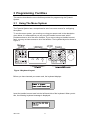
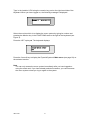
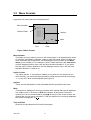
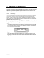
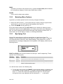


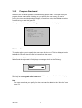

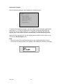
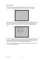


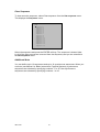


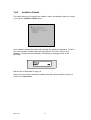
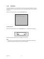
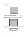
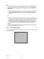

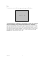
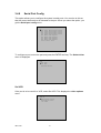
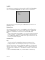
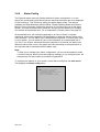
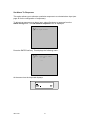
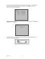


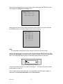

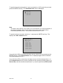

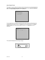
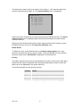

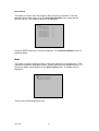
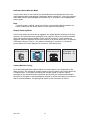
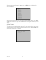
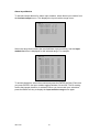
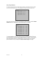
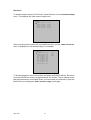
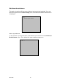
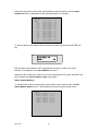
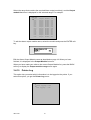


![高圧真空遮断器[EH747n]](http://vs1.manualzilla.com/store/data/006663559_3-3158f34bffed1c86f15f2563db6fce6a-150x150.png)