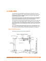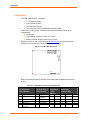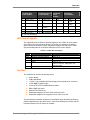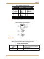
1
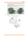
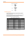
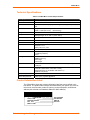
Embedded Integration Kit Integration Guide Part Number 900-316 Revision C October 2004 Copyright and Trademark © 2004, Lantronix. All rights reserved. No part of the contents of this book may be transmitted or reproduced in any form or by any means without the written permission of Lantronix. Printed in the United States of America. Ethernet is a trademark of XEROX Corporation. UNIX is a registered trademark of The Open Group. Windows 95, Windows 98, Windows 2000, and Windows NT are trademarks of Microsoft Corp. Netscape is a trademark of Netscape Communications Corporation. Disclaimer and Revisions Operation of this equipment in a residential area is likely to cause interference, in which case the user, at his or her own expense, will be required to take whatever measures may be required to correct the interference. Changes or modifications to this device not explicitly approved by Lantronix will void the user's authority to operate this device. The information in this guide may change without notice. The manufacturer assumes no responsibility for any errors which may appear in this guide. Date Rev. Comments 12/03 A This Integration Guide, which was previously part of the Embedded Integration Kit User Manual, includes the Micro100, but no longer covers the UDS-10B. 6/04 B Updated guide. 10/04 C Removed references to out of date guides. Contacts Lantronix Corporate Headquarters 15353 Barranca Parkway Irvine, CA 92618, USA Phone: 949-453-3990 Fax: 949-453-3995 Technical Support Phone: 800-422-7044 or 949-453-7198 Fax: 949-450-7226 Online: www.lantronix.com/support E-mail [email protected] Sales Offices For a current list of our domestic and international sales offices, go to the Lantronix web site at http://www.lantronix.com/about/contact/index.html. Embedded Integration Kit Integration Guide i Contents Copyright and Trademark _________________________________________________ i Disclaimer and Revisions__________________________________________________ i Contacts_______________________________________________________________ i 1: Introduction 1-1 Embedded Integration Kits_______________________________________________1-1 About this Guide ______________________________________________________1-1 Purpose and Audience ______________________________________________________ 1-1 Chapter Summary _________________________________________________________ 1-1 Additional Documentation _______________________________________________1-2 2: CoBox-Micro 2-1 Layout and Dimensions _________________________________________________2-1 Connectors___________________________________________________________2-2 Ethernet Interface _____________________________________________________2-3 Status LEDs __________________________________________________________2-3 Test Bed_____________________________________________________________2-4 Board Layout _________________________________________________________2-5 Test Bed Connectors ___________________________________________________2-6 Technical Specifications ________________________________________________2-7 Product Information Label _______________________________________________2-7 3: Micro100 3-1 Layout and Dimensions _________________________________________________3-1 Connectors___________________________________________________________3-2 Ethernet Interface _____________________________________________________3-3 Status LEDs __________________________________________________________3-4 Test Bed_____________________________________________________________3-4 Board Layout _________________________________________________________3-5 Test Bed Connectors ___________________________________________________3-6 Technical Specifications ________________________________________________3-7 Product Information Label _______________________________________________3-7 4: CoBox-Mini 4-1 Layout and Dimensions _________________________________________________4-1 Connectors___________________________________________________________4-2 LED Control Signals____________________________________________________4-3 Test Bed_____________________________________________________________4-3 Board Layout _________________________________________________________4-4 Test Bed Connectors ___________________________________________________4-4 Status LEDs __________________________________________________________4-5 Technical Specifications ________________________________________________4-6 Product Information Label _______________________________________________4-7 5: CoBox-Mini100 5-1 Layout and Dimensions _________________________________________________5-1 Connectors___________________________________________________________5-1 LED Control Signals____________________________________________________5-3 Test Bed_____________________________________________________________5-3 Board Layout _________________________________________________________5-4 Test Bed Connectors ___________________________________________________5-5 Status LEDs __________________________________________________________5-5 Technical Specifications ________________________________________________5-6 Product Information Label _______________________________________________5-7 Embedded Integration Kit Integration Guide ii 6: Integration Guidelines 6-1 Test Environment _____________________________________________________ 6-1 First Setup________________________________________________________________ 6-1 Second Setup _____________________________________________________________ 6-1 EMI Test Results___________________________________________________________ 6-2 General Guidelines ____________________________________________________ 6-4 Power Supply _____________________________________________________________ 6-4 Network Connector _________________________________________________________ 6-5 Virtual Ground _____________________________________________________________ 6-5 Serial Signals _____________________________________________________________ 6-6 Additional Emission Improvements_____________________________________________ 6-6 CoBox-Mini Ethernet Integration_______________________________________________ 6-6 CoBox-Mini100 ____________________________________________________________ 6-6 CoBox-Micro and Micro100 __________________________________________________ 6-6 A: Compliance and Warranty Information A-1 Conformity Information _________________________________________________ A-1 Warranty ____________________________________________________________ A-2 Embedded Integration Kit Integration Guide iii List of Figures Figure 2-1. CoBox-Micro, Top View ___________________________________________2-1 Figure 2-2 - CoBox-Micro, Connector End View _________________________________2-2 Figure 2-3. CoBox-Micro Connectors __________________________________________2-2 Figure 2-4. RJ45 Ethernet Connector__________________________________________2-3 Figure 2-5. CoBox-Micro Status LEDs _________________________________________2-4 Figure 2-6. Carrier Board ___________________________________________________2-5 Figure 2-7. Pin Configurations _______________________________________________2-6 Figure 3-1. Micro100, Top View ______________________________________________3-1 Figure 3-2. Micro100, Connector End View _____________________________________3-2 Figure 3-3. Micro100 Connectors _____________________________________________3-2 Figure 3-4. RJ45 Ethernet Connector__________________________________________3-3 Figure 3-5. Micro100 Status LEDs ____________________________________________3-4 Figure 3-6. Micro100 Test Bed _______________________________________________3-5 Figure 3-7. Carrier Board ___________________________________________________3-5 Figure 3-8. Pin Configurations _______________________________________________3-6 Figure 4-1. CoBox-Mini, Top View ____________________________________________4-1 Figure 4-2. CoBox-Mini Connectors ___________________________________________4-2 Figure 4-3. CoBox-Mini Carrier Board _________________________________________4-4 Figure 4-4. CoBox-Mini Pinout Configurations ___________________________________4-5 Figure 5-1. CoBox-Mini100, Top View _________________________________________5-1 Figure 5-2. CoBox-Mini100 Connectors ________________________________________5-2 Figure 5-3. CoBox-Mini100 Carrier Board ______________________________________5-4 Figure 5-4. CoBox-Mini100 Pinout Configurations ________________________________5-5 Figure 6-1. Multi-Layer Board Strategy ________________________________________6-5 List of Tables Table 2-1. CoBox-Micro Connector Pinouts _____________________________________2-2 Table 2-2. CoBox-Micro Status LEDs__________________________________________2-4 Table 2-3. CoBox-Micro Test Bed Connectors___________________________________2-6 Table 2-4. CoBox-Micro Technical Specifications ________________________________2-7 Table 3-1. Micro100 Connector Pinouts ________________________________________3-2 Table 3-2. Micro100 Status LEDs ____________________________________________3-4 Table 3-3. Micro100 Test Bed Connectors______________________________________3-6 Table 3-4. Micro100 Technical Specifications ___________________________________3-7 Table 4-1. CoBox-Mini Connector Pinouts (Ethernet) _____________________________4-2 Table 4-2. CoBox-Mini LED Signals ___________________________________________4-3 Table 4-3. CoBox-Mini Test Bed Connectors ____________________________________4-5 Table 4-4. CoBox-Mini Status LEDs___________________________________________4-5 Table 4-5. Technical Specifications ___________________________________________4-6 Table 5-1. CoBox-Mini100 Connector Pinouts ___________________________________5-2 Table 5-2. CoBox-Mini100 LED Signals ________________________________________5-3 Table 5-3. CoBox-Mini100 Test Bed Connectors _________________________________5-5 Table 5-4. CoBox-Mini100 Status LEDs________________________________________5-6 Table 5-5. Technical Specifications ___________________________________________5-6 Table 6-1. dBµV CoBox-Micro Results_________________________________________6-2 Table 6-2. Micro100 Results_________________________________________________6-3 Table 6-3. CoBox-Mini Results_______________________________________________6-3 Table 6-4. CoBox-Mini100 __________________________________________________6-4 iv Embedded Integration Kit Integration Guide 1: Introduction Embedded Integration Kits The Lantronix Embedded Integration Kits (Mini-Kit, Mini100-Kit, Micro-Kit, Micro100Kit) provide a simple method of evaluating our CoBox-Mini, CoBox-Mini100, CoBoxMicro, and Micro100 embedded device servers. These kits allow software engineers to test our device servers with their products prior to the hardware development of those products. Each kit contains an embedded device server, board carrier unit, and all the connectors and data needed to interface our product with your serial device. The Embedded Integration Kits include the following: An embedded device server: CoBox-Micro, Micro100, CoBox Mini, or CoBoxMini100 Board carrier unit with serial (DB9) interface. (Some carriers also have RJ45 Ethernet) Power supply CAT5 Ethernet cable, RJ45M/M, 10-foot 10-foot serial cable, DB9 (cable end depends on kit) DB9 to DB-25 converter User Guide (on CD): installation, firmware configurations, application examples, technical tips Software CD: latest Com Port Redirector, Device Installer, and firmware About this Guide Purpose and Audience This guide provides the information needed to test the embedded device server on the Evaluation Board. The intended audience is the engineer responsible for integrating the device server into your product. Chapter Summary The remaining chapters in this guide include: 2: CoBox-Micro Describes and provides information about the CoBox Micro and its integration kit. 3:2: Micro100 Describes and provides information about the Micro100 and its integration kit. 4: Cobox-Mini Describes and provides information about the CoBox Mini and its integration kit. Embedded Integration Kit Integration Guide 1-1 Introduction 5: CoBoxMini100 Describes and provides information about the CoBox Mini100 and its integration kit. 6: Integration Guidelines Describes the test setup and resultant emission profiles of the CoBox-Mini, CoBox-Mini100, CoBox-Micro, and Micro100. Provides general guidelines to help you reach the necessary standards for your applications. Additional Documentation The following guides are available on the product CD and the Lantronix Web site (www.lantronix.com) 1-2 Embedded Integration Kit User Guide Provides information needed to configure, use, and update the firmware. Device Installer User Guide Provides instructions on using the Windows-based utility used to configure Lantronix embedded device servers. Com Port Redirector User Guide Provides information on using the Windows-based utility to create a virtual com port. Embedded Integration Kit Integration Guide 2: CoBox-Micro The CoBox-Micro integrates into products quickly and easily. Serial interfacing is accomplished via a TTL connector, and for Ethernet access, an optional RJ45 (10Base-T) connector is available. You can specify the orientation of the unit’s interface pins to fit your product. It requires 5 volts DC of regulated power with maximum current of 200mA. Layout and Dimensions The following drawing is a top view of the CoBox-Micro. Figure 2-1. CoBox-Micro, Top View O .130 3 places .100 .330 .620 .100 .830 1.375 1.575 .724 .120 .095 Use this hole for chassis ground .100 .050 .100 .739 .100 1.530 1.935 The following drawing shows the connector end view of the board with the LEDs and RJ45 connector installed. The drawing on the right shows the dimensions for CON1 (DIL 2 x 6). Embedded Integration Kit Integration Guide 2-1 CoBox-Micro Figure 2-2 - CoBox-Micro, Connector End View .200 .400 O .115 (Note 1) .200 .068 .465 .170 .065 .400 .150 .087 .060 .360 .265 .480 .625 CONNECTOR END VIEW 1. This is the highest component on the board. Connectors The CoBox-Micro has four connectors: a TTL serial port (CON1), a 10Base-T RJ45 Connector (CON2), and/or pins instead of the RJ45 connector (CON3), and LEDs (CON4). Figure 2-3. CoBox-Micro Connectors CON2 (RJ45) 12 3 2 1 8 7 CON3 CON1 (TTL) 11 4 2 1 CON4 (LEDs) 2 1 S1 The CoBox-Micro that comes with the integration kit is factory configured. When ordering the CoBox-Micro for production use, you can specify each connector as follows: Pins on/off the board and top/bottom (see Figure 2-2 and Figure 2-3) LEDs on/off the board RJ45 on/off the board Contact Lantronix for information about ordering the CoBox-Micro with customized connector configurations. The Embedded Integration Kit (part number Micro-Kit) includes the CoBox-Micro embedded device server. Refer to the following table for a listing of its pinouts. Table 2-1. CoBox-Micro Connector Pinouts CON1 TTL Serial Port (DIL 2 x 6 Pins) Pin Signal 1 2-2 +5VDC CON2 10Base-T (RJ45) Connector Pin Signal 1 Tx+ CON3 (2 x 2 Pins in place of RJ45) Pin Signal 1 Tx+ CON4 (2 x 4 Pins in place of LEDs) Pin Signal 1 +5VDC Embedded Integration Kit Integration Guide CoBox-Micro CON1 TTL Serial Port (DIL 2 x 6 Pins) Pin Signal CON2 10Base-T (RJ45) Connector Pin Signal CON3 (2 x 2 Pins in place of RJ45) Pin Signal CON4 (2 x 4 Pins in place of LEDs) Pin Signal 2 GND 2 Tx- 2 Tx- 2 +5VDC 3 RxA (input) 3 Rx+ 3 Rx+ 3 LED3 (Diagnostics)* 4 TxA (output) 4 None 4 Rx- 4 LED1 (Channel 1)* 5 RTSA (output) 5 None 5 +5VDC 6 DTRA (output) 6 Rx- 6 +5VDC 7 CTSA (input) 7 None 7 LED2 (Channel 2)* 8 DCDA (input) 8 None 8 LED4 (Link)* 9 Reserved 10 RESET (pull low to reset) 11 RxB (input) 12 TxB (output) * Current limiting resistor on board is 680 Ohms. A = Port (Channel) 1 B = Port (Channel) 2 Ethernet Interface The standard CoBox-Micro ships with an RJ45 10Base-T Ethernet connector (CON2). At the time of ordering, you can specify whether to include this RJ45 connector. You can use CON3 as an alternative. Figure 2-4. RJ45 Ethernet Connector 1 8 1 - TX+ 2 - TX3 - RX+ 6 - RX- Status LEDs The CoBox-Micro has four status LEDs: serial port (Channel) 1 status, serial port (Channel) 2 status, diagnostics, and network link status. See the following table for a complete description of status LED pinout location and function. Embedded Integration Kit Integration Guide 2-3 CoBox-Micro Figure 2-5. CoBox-Micro Status LEDs Green 1 4 Green Red 3 2 Yellow Table 2-2. CoBox-Micro Status LEDs LED Description Location LED Functions 1 Serial Port (Channel) 1 Status CON 4, Pin 4 Lights solid green to indicate Channel 1 is idle. Blinks green to indicate Channel 1 is connected to the network and active. 2 Serial Port (Channel) 2 Status CON 4, Pin 7 Lights solid yellow to indicate Channel 2 is idle. Blinks yellow to indicate Channel 2 is connected to the network and active. 3 Diagnostics CON 4, Pin 3 Blinks or lights solid red in combination with the green (Channel 1) LED to indicate diagnostics and error detection. Red solid, green (Channel 1) blinking: 1x: EPROM checksum error 2x: RAM error 3x: Network controller error 4x: EEPROM checksum error 5x: Duplicated IP address on the network* 6x: Software does not match hardware* Red blinking, green (Channel 1) blinking: 4x: Faulty network connection* 5x: No DHCP response received* 4 Network Link Status CON 4, Pin 8 Lights solid green to indicate network port is connected to the network. *non-fatal error Test Bed The evaluation kit contains the following items: Carrier Board CoBox-Micro Board +5VDC International Power Supply with universal power connector 10-foot DB9M/F RS232 Cable 10-foot UTP CAT5e RJ45M/M Ethernet Cable DB9 to DB25 Converter Software CD (CD-EIK-xx) Embedded Integration Kit User Guide, 900-226 on CD Embedded Integration Kit Integration Guide, 900-316 on CD The CoBox-Micro Embedded Integration Kit (part number Micro-Kit) includes a test bed (carrier board) that provides serial connections to the device server. The CoBoxMicro device server provides the network 2-4 Embedded Integration Kit Integration Guide CoBox-Micro 10Base-T RJ45. The test bed contains a power LED, TTL- to-RS232 and RS232-toTTL conversion hardware, a 3-pin connector for the second serial port, and mounting hardware for the CoBox-Micro. The test bed allows software engineers to immediately begin developing and testing software applications for the device server, rather than delaying the process until the hardware interface for their product is complete. Board Layout Install the CoBox-Micro onto the carrier board as shown below. Figure 2-6. Carrier Board CON4 J1 CON2 CON1 5 9 Embedded Integration Kit Integration Guide 1 CON3 (PWR) 6 2-5 CoBox-Micro Figure 2-7. Pin Configurations 1 DTRA TXA RXA DCDA GND 5 CON1 6 CTSA RTSA 9 2 1 GND RXA DCDA DTRA CON2 +5VDC TXA CTSA RTSA RXB TXB 12 11 TXB CON4 GND RXB Test Bed Connectors The CoBox-Micro test bed has four connectors: CON1 (Serial Port 1 or Channel 1), CON2 (TTL Interface), CON4 (Serial Port 2 or Channel 2), and CON3, which is a 5VDC power supply connector. This RS232 level serial interface is implemented with a DB9F connector. The CoBox Micro converts the RS232 serial transmit and receive data of this interface to Ethernet protocol transmit and receive data. The DB9 connector is compatible with most PC serial interface ports using a straight through cable. Table 2-3. CoBox-Micro Test Bed Connectors CON1 Serial Port (Channel) 1a Pin Signal CON2 TTL Interface Pin Signal CON4 Serial Port (Channel) 2b Pin Signal 1 DTRA (output) 1 +5 VDC 1 TxB (output) 2 TxA (output) 2 GND 2 RxB (input) 3 RxA (input) 3 TxA (output) 3 GND 4 DCDA (input) 4 RxA (input) 5 GND 5 CTSA (input) 6 None 6 DCDA (input) 7 CTSA (input) 7 RTSA (output) 8 RTSA (output) 8 DTRA (output) 9 None 9 None 10 None 11 TxB (output) 12 RxB (input) a. CON1 Serial Port (Channel) 1 is also designated as A. b. CON4 Serial Port (Channel) 2 is also designated as B. Note: CON3 is a PCB-mounted, center-positive 5VDC power supply connector. 2-6 Embedded Integration Kit Integration Guide CoBox-Micro Technical Specifications Table 2-4. CoBox-Micro Technical Specifications Category Description Memory 128K RAM, 512 Bytes NVRAM Serial Flash 128K Serial Interface 1 TTL serial interface (Async). 5V-level signals. Through-hole plated pins, DIL Board Dimensions Height: 1.575in (40.00 mm) Width: 1.935in (49.15 mm) Weight 0.7 ounces Temperature Operating range: 0° to +70° C (32 to 158° F) Storage range: -40° to +85° C (-40 to 185° F) Protocols Supported ARP, UDP, TCP, Telnet, ICMP, SNMP, DHCP, TFTP, AutoIP, and HTTP Network Interface RJ45 10Base-T (See Drawing) Data Rates 300 bps to 115.2 Kbps Serial Line Formats Characters: 7 or 8 data bits Stop bits: 1 or 2 Parity: odd, even, none Modem Control DTR, DCD, CTS, RTS Flow Control XON/XOFF (software), XON/XOFF Pass Characters to Host CTS/RTS (hardware) None Management HTTP SNMP (read only) Serial login Telnet login System Software Flash ROM standard: downloadable from a TCP/IP host (TFTP) or over serial port LEDs Channel 1 (solid Green = idle, blink = active) Channel 2 (solid Yellow = idle, blink = active) Diagnostics (Red, in combination with Channel 1) Network Link (Green) Compatibility Ethernet: Version 2.0/IEEE 802.3 Power Requirements 5VDC (±5%) regulated @ 200mA Product Information Label The CoBox-Micro ships with a product information label that can be affixed to the host device. The product label contains information about your specific unit, such as its bar code, serial number, product ID (name), product description, and Ethernet address (also referred to as hardware address or MAC address). S/N:7401362 CO-E1-11AA 00-20-4A-74-05-52 Rev. C12 Made in USA Embedded Integration Kit Integration Guide Serial Number Part Number MAC ID Revision 2-7 3: Micro100 The Micro100 integrates into products quickly and easily. Serial interfacing is accomplished via a TTL connector, and for Ethernet access, an optional RJ45 (10/100Base-T) connector is available. The orientation of its interface pins can be specified to fit your product. It requires 5 volts DC of regulated power with maximum current of 200mA. Layout and Dimensions The following drawing is a top view of the Micro100. Figure 3-1. Micro100, Top View The following drawing shows the connector end view of the board with the LEDs and RJ45 connector installed. The drawing on the right shows the dimensions for CON1 (DIL 2 x 6). Embedded Integration Kit Integration Guide 3-1 Micro100 Figure 3-2. Micro100, Connector End View .200 .400 O .115 (Note 1) .200 .068 .465 .170 .087 .065 .265 .360 .480 .625 .400 .150 .060 CONNECTOR END VIEW 1. This is the highest component on the board. Connectors The Micro100 has four connectors: a TTL serial port (CON1), a 10/100Base-T RJ45 Connector (CON2), and/or pins instead of the RJ45 connector (CON3) and LEDs (CON4). Figure 3-3. Micro100 Connectors CON2 (RJ45) 12 4 3 2 1 8 7 CON3 2 CON1 (TTL) 11 1 CON4 (LEDs) 2 1 S1 The Micro100 that comes with the integration kit is factory configured. When ordering the Micro100 for production use, each connector can be specified as follows: Pins on/off the board and top/bottom (Figure 3-2, Figure 3-3) LEDs on/off the board RJ45 on/off the board Contact Lantronix for information about ordering the Micro100 with customized connector configurations. The Embedded Integration Kit (part number Micro-Kit) includes the Micro100 embedded device server. Refer to the following table for a listing of its pinouts. Table 3-1. Micro100 Connector Pinouts CON1 TTL Serial Port (DIL 2 x 6 Pins) 3-2 Pin Signal CON2 10/100Base-T (RJ45) Connector Pin Signal 1 +5VDC 1 Tx+ CON3 (2 x 2 Pins in place of RJ45) CON4 (2 x 4 Pins in place of LEDs) Pin Signal Pin Signal 1 Tx+ 1 +3.3 VDC Embedded Integration Kit Integration Guide Micro100 CON1 TTL Serial Port (DIL 2 x 6 Pins) Pin Signal CON2 10/100Base-T (RJ45) Connector Pin Signal CON3 (2 x 2 Pins in place of RJ45) CON4 (2 x 4 Pins in place of LEDs) Pin Signal Pin Signal 2 GND 2 Tx- 2 Tx- 2 +3.3 VDC 3 RxA (input) 3 Rx+ 3 Rx+ 3 LED3 (Diagnostics)1 4 TxA (output) 4 None 2 (tied to Pin 5) 4 Rx- 4 LED1 (Channel 1) 1 5 RTSA (output) 5 None (tied to Pin 4) 5 +3.3 VDC 6 DTRA (output) 6 Rx- 6 +3.3 VDC 7 CTSA (input) 7 None (tied to Pin 8) 7 LED2 (Channel 2) 1 8 DCDA (input) 8 None (tied to Pin 7) 8 LED4 (Link) 1 9 Reserved 10 RESET (pull low to reset) 11 RxB (input) 12 TxB (output) 1 Current limiting resistor on board is 220 Ohms. 150 Ohms exist between the Pin 4/5 node and the Pin 7/8 node. A = Port (Channel) 1 B = Port (Channel) 2 2 Ethernet Interface The standard Micro100 ships with an RJ45 10/100Base-T Ethernet connector (CON2). At the time of ordering, you can specify whether to include this RJ45 connector. You can use CON3 as an alternative. Figure 3-4. RJ45 Ethernet Connector 1 8 1 - TX+ 2 - TX3 - RX+ 6 - RX- Embedded Integration Kit Integration Guide 3-3 Micro100 Status LEDs The Micro100 has four status LEDs: serial port (Channel) 1 status, serial port (Channel) 2 status, diagnostics, and network link status. See the following table for a complete description of status LED pinout location and function. Figure 3-5. Micro100 Status LEDs (Serial Port 1) Green 1 4 Green (Link) (Diagnostics) Red 3 2 Yellow (Serial Port 2) Table 3-2. Micro100 Status LEDs LED Description Location LED Functions 1 SerialPort (Channel) 1 Status SerialPort (Channel) 2 Status Diagnostics CON 4, Pin 4 Lights solid green to indicate Channel 1 is idle. Blinks green to indicate Channel 1 is connected to the network and active. Lights solid yellow to indicate Channel 2 is idle. Blinks yellow to indicate Channel 2 is connected to the network and active. Blinks or lights solid red in combination with the green (Channel 1) LED to indicate diagnostics and error detection. 2 3 CON 4, Pin 7 CON 4, Pin 3 Red solid, green (Channel 1) blinking: 3x: Network controller error 5x: Duplicated IP address on the network* Red blinking, green (Channel 1) blinking: 5x: No DHCP response received* 4 Network Link Status *non-fatal error CON 4, Pin 8 Lights solid green to indicate network port is connected to the network. Test Bed The evaluation kit contains the following items: 3-4 Carrier Board Micro100 Board +5VDC International Power Supply with universal power connector 10-foot DB9M/F RS232 Cable 10-foot UTP CAT5e RJ45M/M Ethernet Cable DB9 to DB25 Converter Software CD (CD-EIK-xx) Embedded Integration Kit User Guide, 900-226 on CD Embedded Integration Kit Integration Guide, 900-316 on CD Embedded Integration Kit Integration Guide Micro100 The Micro100 Embedded Integration Kit (part number Micro100-Kit) includes a test bed (carrier board) that provides serial connections to the device server. The Micro100 device server provides a network 10/100Base-T RJ45. The test bed contains a power LED, TTL to RS-232 and RS-232 to TTL conversion hardware, a 3pin connector for the second serial port, and mounting hardware for the Micro100. The test bed allows software engineers to immediately begin developing and testing software applications for the device server, rather than delaying the process until the hardware interface for their product is complete. Figure 3-6. Micro100 Test Bed Board Layout Install the Micro100 onto the carrier board as shown below. Figure 3-7. Carrier Board Embedded Integration Kit Integration Guide 3-5 Micro100 Figure 3-8. Pin Configurations Test Bed Connectors The Micro100 test bed has four connectors: CON1 (Serial Port 1 or Channel 1), CON2 (TTL Interface), CON4 (Serial Port 2 or Channel 2), and CON3, which is a 5VDC power supply connector. This RS-232 level serial interface is implemented with a DB9F connector. The Micro100 converts the RS-232 serial transmit and receive data of this interface to Ethernet protocol transmit and receive data. The DB9 connector was selected for compatibility with most PC serial interface ports using a straight through cable. Table 3-3. Micro100 Test Bed Connectors CON1 Serial Port (Channel) 1a Pin Signal 1 2 3 4 5 6 7 8 9 DTRA (output) TxA (output) RxA (input) DCDA (input) GND None CTSA (input) RTSA (output) None CON2 TTL Interface Pin 1 2 3 4 5 6 7 8 9 10 11 12 Signal +5 VDC GND RxA (output) TxA (input) RTSA (input) DTRA (input) CTSA (output) DCDA (output) None None RxB (output) TxB (input) CON4 Serial Port (Channel) 2b Pin Signal 1 2 3 TxB (output) RxB (input) GND a. CON1 Serial Port (Channel) 1 is also designated as A. b. CON4 Serial Port (Channel) 2 is also designated as B. 3-6 Embedded Integration Kit Integration Guide Micro100 Note: CON3 is a PCB-mounted, center-positive 5VDC power supply connector. Technical Specifications Table 3-4. Micro100 Technical Specifications Category Description Memory Serial Flash Serial Interface 256K RAM 512 K 2 TTL serial interfaces (Async). 5V-level signals. Through-hole plated pins, DIL Height: 1.575in (40.00 mm) Width: 1.935in (49.15 mm) (See Drawing) 0.7 ounces Operating range: 0° to +70° C (32 to 158° F) Storage range: -40° to +85° C (-40 to 185° F) ARP, UDP, TCP, Telnet, ICMP, SNMP, DHCP, TFTP, AutoIP, and HTTP RJ45 10/100Base-T 300 bps to 230400 bps Characters: 7 or 8 data bits Stop bits: 1 or 2 Parity: odd, even, none DTR, DCD, CTS, RTS XON/XOFF (software), XON/XOFF Pass Characters to Host CTS/RTS (hardware) None HTTP SNMP (read only) Serial login Telnet login Operational code (ROM): downloadable from a TCP/IP host (TFTP) or over serial port Channel 1 (solid Green = idle, blink = active) Channel 2 (solid Yellow = idle, blink = active) Diagnostics (Red, in combination with Channel 1) Network Link (Green) Ethernet: Version 2.0/IEEE 802.3 5VDC (±5%) regulated @ 200mA Board Dimensions Weight Temperature Protocols Supported Network Interface Data Rates Serial Line Formats Modem Control Flow Control Management System Software LEDs Compatibility Power Requirements Product Information Label The Micro100 ships with a product information label that can be affixed to the host device. The product label contains information about your specific unit, such as its part number, revision number, manufacturing code, and Ethernet address (also referred to as hardware address or MAC address). Part Number Manufacturing Code Revision Number MAC Address Embedded Integration Kit Integration Guide 3-7 4: CoBox-Mini The CoBox-Mini can be designed as an attachment to a PCB board. The serial interface is accomplished via TTL connectors, which include transmit, receive, and full handshaking. UTP or AUI network interfaces can be utilized. The CoBox-Mini supports network speeds of 10Mbps. Both the length and orientation of the CoBox-Mini’s interface pins can be specified to fit your product’s architectural requirements. The CoBox-Mini requires 5 volts DC of regulated power with maximum current of 200mA for normal operation. The CoBox-Mini’s well-developed IP firmware supports protocols such as ARP, UDP, TCP, BOOTP, Telnet, ICMP, SNMP, DHCP, TFTP, AutoIP, and HTTP, as well as other custom protocols. The CoBox-Mini also supports a variety of user-configurable options such as buffer control and packetization, which make it easy to use in most applications. Note: This manual documents the present version (Rev 2) of the CoBox-Mini. This latest version of the CoBox-Mini is distinguished from the earlier version by its dual TTL serial ports (CON1 and CON4). The earlier version had one TTL serial port. Layout and Dimensions The following drawing is a top view of the CoBox-Mini. Figure 4-1. CoBox-Mini, Top View O 3.0 (0.118) 4x 9.8 (0.386) 5.08 (0.2) 3.5 (0.138) 2.7 (0.106) CON1 15.9 (0.626) CON4 CON2 2.54 (0.1) 70.0 +/-0.2 (2.756 +/- 0.008) UNITS: mm (in) 65.0 (2.559) CON3 2.5 (0.098) 2.5 (0.098) 10.5 (0.413) 75.0 (2.953) 80.0 +/-0.2 (3.150 +/- 0.008) Embedded Integration Kit Integration Guide 2.54 (0.100) 7.27 (0.282) 1.57 (0.062) 5.7 (0.22) 4-1 CoBox-Mini Connectors The CoBox-Mini has four connectors: TTL serial port (CON1) AUI connector (CON2) UTP connector (CON3) TTL serial port 2 and full handshaking signals (CON4) At the time of ordering, each connector can be specified with the following pin configurations: Not present Top mounted, length of 5.46 mm or 6.76 mm Bottom mounted, length of 5.46 mm or 6.76 mm Contact Lantronix or visit our Web site (www.lantronix.com) for information about ordering device servers with various connector configurations. Figure 4-2. CoBox-Mini Connectors 1 10 1 CON1 CON2 CON4 1 6 CON3 7 1 Refer to the following table for a listing of the CoBox-Mini embedded device server pinouts. Table 4-1. CoBox-Mini Connector Pinouts (Ethernet) CON1 TTL Serial Port (10-Pin Header) Pin 1 2 3 4 5 4-2 Signal +5VDC GND TxA (output) RxA (input) RESET (pull low to reset) CON4 TTL Serial Port (1) (10-Pin Header) Pin 1 2 3 4 5 Signal DTRA (output) GND RxB (input) TxB (output) CTSA (input) CON2 AUI Connector (6-Pin Header) Pin 1 2 3 4 5 Signal CD+ CDRx+ RxTx+ CON3 10 Base-T Connect/or (7-Pin Header) Pin 1 2 3 4 5 Signal Tx+ RJ45 1 TxRx+ RxNone Embedded Integration Kit Integration Guide 2 3 6 CoBox-Mini CON1 TTL Serial Port (10-Pin Header) Pin 6 Signal DCDA (input) CON4 TTL Serial Port (1) (10-Pin Header) Pin 6 7 LED1 (Channel 1) 7 8 LED2 (Channel 2) 8 9 LED3 (Diagnostic) 10 +5VDC (for LEDs) A = Port (Channel) 1 (1) with Full Handshaking Signal CTSB (input) CON2 AUI Connector (6-Pin Header) Pin 6 Signal Tx- RTSA (output) CON3 10 Base-T Connect/or (7-Pin Header) Pin 6 7 Signal LED 4 (Link) +5VDC (LED) RJ45 DTRB (output) 9 DCDB (input) 10 RTSB (output) B = Port (Channel) 2 LED Control Signals The CoBox-Mini has no LEDs but provides signals to drive LEDs. All of the signals drive LEDs on the test bed carrier board. The signals are: serial port (Channel) 1 status, serial port (Channel) 2 status, diagnostics, network link status, and +5VDC. See the following table for a complete description of LED control signals. Table 4-2. CoBox-Mini LED Signals LED Signal Description Signal Pin LED1 LED2 LED3 LED4 SerialPort (Channel) 1 Status SerialPort (Channel) 2 Status Diagnostic Network Link Status +5VDC CON1, Pin 7 CON1, Pin 8 CON1, Pin 9 CON3, Pin 6 CON1, Pin 10 Power for Channel 1, Diagnostics, and Channel 2 LEDs CON3, Pin 7, Power for Link LED +5VDC Test Bed The evaluation kit contains the following items: Carrier Board CoBox-Mini Board +12VDC, 0.8A, International Power Supply with universal power connector 10-foot DB9F/F RS232 Cable 10-foot UTP CAT5e RJ45M/M Ethernet Cable DB9 to DB25 Converter Software CD (CD-EIK-xx) Embedded Integration Kit User Guide, 900-226 on CD Embedded Integration Kit Integration Guide, 900-316 on CD The test bed allows software engineers to immediately begin developing and testing software applications for the device server, rather than delaying the process until the hardware interface for their product is complete. Embedded Integration Kit Integration Guide 4-3 CoBox-Mini Board Layout Figure 4-3. CoBox-Mini Carrier Board 9 6 9 6 DB-9M 5 CON1 PWR 1 5 1 CON8 CH2 CON7 CH1 Reset Switch LED1 (Green) LED2 (Yellow) 1 10 1 10 LED3 (Red) 1 6 7 1 CON4 LED4 (Link) LED5 (100MBit) 1 8 Test Bed Connectors The CoBox-Mini test bed has five external connectors: 4-4 CON4 (a 10Base-T RJ45 Connector) CON7 (Serial Port 1or Channel 1) CON8 (Serial Port 2 or Channel 2) CON1 (a 9-30 VDC power supply connector) (also accepts 9 -25 VAC) Embedded Integration Kit Integration Guide CoBox-Mini Table 4-3. CoBox-Mini Test Bed Connectors CON4 10Base-T (RJ45) CON7 Serial Port (Channel) 1(Note A) CON8 Serial Port (Channel) 2(Note B) Pin 1 2 3 4 Signal Tx+ TxRx+ Decoupling Pin 1 2 3 4 Pin 1 2 3 4 Signal DCDB (input) RxB (input) TxB (output) DTRB (output) 5 6 7 Decoupling RxDecoupling 5 6 7 5 6 7 GND None RTSB (output) 8 Decoupling 8 9 8 9 CTSB (input) None Signal DCDA (input) RxA (input) TxA (output) DTRA (output) GND None RTSA (output) CTSA (input) None A. Serial Port (Channel) 1 is also designated as A. B. Serial Port (Channel) 2 is also designated as B. Note: CON1 is a PCB-mounted, center-positive 9-30VDC power supply connector. Figure 4-4. CoBox-Mini Pinout Configurations 1 8 1 - TX+ 2 - TX3 - RX+ 6 - RX- CON4 (RJ45) 5 CON7 (DB-9M) CON8 (DB-9M) GND DTRA TXA RXA DCDA 9 CTSA RTSA 1 6 5 9 GND DTRB TXB RXB DCDB CTSB RTSB 1 6 Status LEDs The CoBox-Mini carrier board has four status LEDs: serial port (Channel) 1 status, serial port (Channel) 2 status, diagnostics, and network link status. See the following table for a complete description of LED functions and pinout locations. Table 4-4. CoBox-Mini Status LEDs LED Description Location LED Functions 1 SerialPort (Channel) 1 Status SerialPort (Channel) 2 Status CON 1, Pin 7 Lights solid green to indicate Channel 1 is idle. Blinks green to indicate Channel 1 is connected to the network and active. Lights solid yellow to indicate Channel 2 is idle. Blinks yellow to indicate Channel 2 is connected to the network and active. 2 CON 1, Pin 8 Embedded Integration Kit Integration Guide 4-5 CoBox-Mini LED Description Location LED Functions 3 Diagnostics CON 1, Pin 9 Blinks or lights solid red in combination with the green (Channel 1) LED to indicate diagnostics and error detection. Red solid, green (Channel 1) blinking: 1x: EPROM checksum error 2x: RAM error 3x: Network controller error 4x: EEPROM checksum error 5x: Duplicated IP address on the network* 6x: Software does not match hardware* Red blinking, green (Channel 1) blinking: 4x: Faulty network connection* 5x: No DHCP response received* 4 Network Link Status *non-fatal error CON 3, Pin 6 Lights solid green to indicate network port is connected to the network. Technical Specifications Table 4-5. Technical Specifications Category Memory Serial Flash Serial Interface Board Dimensions Weight Temperature Protocols Supported Network Interface Data Rates Serial Line Formats Modem Control Flow Control Management System Software LED Status Lines 4-6 Description 128K SRAM (optional 512) 512K 2 TTL serial interfaces, 5V-level signals Height: 2.756in (70.0 mm) Width: 3.150in (80.0 mm) Depth: .062in (1.57 mm) (See Drawing) 1.1 ounces Operating range: 5° to +50° C (41° to 122° F) Storage Temperature: -40° to +66° C (-40° to 151° F) ARP, UDP, TCP, Telnet, ICMP, SNMP, DHCP, TFTP, HTTP, AutoIP 10Base-T or AUI Ethernet 300 bps to 115.2 Kbps Characters: 7 or 8 data bits Stop bits: 1 or 2 Parity: odd, even, none DTR, DCD, CTS, RTS XON/XOFF (software), XON/XOFF Pass Characters to Host CTS/RTS (hardware) None HTTP SNMP (read only) Serial login Telnet login Flash ROM standard: downloadable from a TCP/IP host (TFTP) or over serial port Channel 1 (solid Green = idle, blink = active) Channel 2 (solid Yellow = idle, blink = active) Diagnostics (Red, in combination with Channel 1) Network Link (Green) Embedded Integration Kit Integration Guide CoBox-Mini Category Compatibility Power Requirements Description Ethernet: Version 2.0/IEEE 802.3, Token Ring: IEEE 802.2 LLC 5VDC (±5%) regulated @ 250mA (Ethernet model), 800mA (Token Ring models) Product Information Label The CoBox-Mini ships with a product information label that can be affixed to the host device. The product label contains information about your specific unit, such as its bar code, serial number, product ID (name), product description, and Ethernet address (also referred to as hardware address or MAC address). S/N:5214931 CM-E2-0000B 00-20-4A-52-3A-53 Rev. C12 Made in USA Embedded Integration Kit Integration Guide Serial Number Part Number MAC ID Revision 4-7 5: CoBox-Mini100 The CoBox-Mini100 can be designed as an attachment to a PCB board. The serial interface is accomplished via TTL connectors, which include transmit, receive, and full handshaking. The CoBox-Mini100 supports network speeds of 10Mbps or 100Mbps. Both the length and orientation of the CoBox-Mini100’s interface pins can be specified to fit your product’s architectural requirements. The CoBox-Mini100 requires 5 volts DC of regulated power with maximum current of 250mA for normal operation. The CoBox-Mini100’s well-developed IP firmware supports protocols such as ARP, UDP, TCP, BOOTP, Telnet, ICMP, SNMP, DHCP, TFTP, AutoIP, and HTTP, as well as other custom protocols. The CoBox-Mini100 also supports a variety of userconfigurable options such as buffer control and packetization, making it easy to use in most applications. Layout and Dimensions The following drawing is a top view of the CoBox-Mini. Figure 5-1. CoBox-Mini100, Top View O 3.0 (0.118) 4x 9.8 (0.386) 5.08 (0.2) 3.5 (0.138) 2.7 (0.106) CON1 CON4 2.54 (0.1) 70.0 +/-0.2 (2.756 +/- 0.008) UNITS: mm (in) 65.0 (2.559) 5.08(0.2) CON2 2.54 (0.100) CON3 2.5 (0.098) 2.5 (0.098) 10.5 (0.413) 75.0 (2.953) 80.0 +/-0.2 (3.150 +/- 0.008) 7.27 (0.282) 1.57 (0.062) 5.7 (0.22) Connectors The CoBox-Mini100 has four connectors: TTL serial port 1 (CON1) 10/100Base-TX (CON2) Embedded Integration Kit Integration Guide 5-1 CoBox-Mini100 10/100Base-T (CON3) TTL serial port 2 (CON4) At the time of ordering, each connector can be specified with the following pin configurations: Not present Top mounted, length of 5.46 mm or 6.76 mm Bottom mounted, length of 5.46 mm or 6.76 mm Contact Lantronix or visit our Web site (www.lantronix.com) for information about ordering device servers with various connector configurations. Figure 5-2. CoBox-Mini100 Connectors CON1 1 1 10 10 CON4 11 CON2 7 CON3 1 1 Refer to the following table for a listing of the CoBox-Mini100 embedded device server pinouts. Table 5-1. CoBox-Mini100 Connector Pinouts 5-2 CON1 TTL Serial Port (10-Pin Header) CON4 TTL Serial Port (10-Pin Header) CON2 10/100BaseTX Connector (11-Pin Header) Pin Signal Pin Signal Pin Signal CON3 10/100Base-T (1) Connector (7-Pin Header) Pin Signal RJ45 1 +5VDC 1 DTRA (output) 1 TX+ 1 Tx+ 1 2 GND 2 GND 2 TX- 2 Tx- 2 3 TxA (output) 3 RxB (input) 3 Rx+ 3 Rx+ 3 4 RxA (input) 4 TxB (output) 4 Decoupling 4 Rx- 6 5 RESET (pull low to reset) 5 CTSA (input) 5 Decoupling 5 Decoupling (Shield) 6 DCDA (input) 6 CTSB (input) 6 Rx- 6 LED 4 (Link) (2) 7 LED1 (Channel 1) 7 RTSA (output) 7 Decoupling 7 +5VDC (LED4) 8 LED2 (Channel 2) 8 DTRB (output) 8 Decoupling 9 LED3 (Diagnostic) 9 DCDB (input) 9 Decoupling 10 +5VDC (for LED 1-3) 10 RTSB (output) 10 LED5 (speed 100Mbit)(2) 11 +5VDC (for LED5) Embedded Integration Kit Integration Guide CoBox-Mini100 CON1 TTL Serial Port (10-Pin Header) A = Port (Channel) 1 CON4 TTL Serial Port (10-Pin Header) CON2 10/100BaseTX Connector (11-Pin Header) CON3 10/100Base-T (1) Connector (7-Pin Header) B = Port (Channel) 2 Notes: 1. For Ethernet connection, either CON2 or CON3 should be used. The use of CON2 is recommended for harsh and noisy environments. 2. LED4 indicates 10M network speed, and LED5 indicates 100M network speed. Both LED4 and LED5 can be used when either CON2 or CON3 is used. LED Control Signals The CoBox-Mini100 has no LEDs but provides signals to drive LEDs. All of the signals drive LEDs on the test bed carrier board. The signals are: serial port (Channel) 1 status, serial port (Channel) 2 status, diagnostics, two network link status, and +5VDC. See the following table for a complete description of LED control signals. Table 5-2. CoBox-Mini100 LED Signals LED Signal Description Signal Pin LED1 SerialPort (Channel) 1 Status CON1, Pin 7 LED2 SerialPort (Channel) 2 Status CON1, Pin 8 LED3 Diagnostic CON1, Pin 9 LED4 10M Network Link Status CON3, Pin 6 LED5 100M Network Link Status CON2, Pin 10 +5VDC CON1, Pin 10, Power for LEDs 1-3 +5VDC CON2, Pin 11, Power for 100M Link LED5 +5VDC CON3, Pin 7, Power for 10M Link LED4 Test Bed The evaluation kit contains the following items: Carrier Board CoBox-Mini100 Board +12VDC, 0.8A, International Power Supply with universal power connector 10-foot DB9F/F RS232 Cable 10-foot UTP CAT5e RJ45M/M Ethernet Cable DB9 to DB25 Converter Software CD (CD-EIK-xx) Embedded Integration Kit User Guide, 900-226 on CD Embedded Integration Kit Integration Guide, 900-316 on CD The test bed allows software engineers to immediately begin developing and testing software applications for the device server, rather than delaying the process until the hardware interface for their product is complete. Embedded Integration Kit Integration Guide 5-3 CoBox-Mini100 Board Layout Figure 5-3. CoBox-Mini100 Carrier Board 9 6 9 6 DB-9M 5 CON1 PWR 1 5 1 CON8 CH2 CON7 CH1 Reset Switch LED1 (Green) LED2 (Yellow) LED3 (Red) 10 10 1 1 11 1 7 1 CON4 LED4 (Link) LED5 (100MBit) 5-4 1 8 Embedded Integration Kit Integration Guide CoBox-Mini100 Test Bed Connectors The CoBox-Mini100 test bed has three external connectors: CON4 (a 10/100Base-TX RJ45 Connector) CON7 (Serial Port 1 or Channel 1) CON8 (Serial Port 2 or Channel 2) Table 5-3. CoBox-Mini100 Test Bed Connectors CON4 10/100Base-TX (RJ45) Pin Signal CON7 Serial Port (Channel) 1(Note A) Pin CON8 Serial Port (Channel) 2(Note B) Signal Pin Signal 1 Tx+ 1 DCDA (input) 1 DCDB (input) 2 Tx- 2 RxA (input) 2 RxB (input) 3 Rx+ 3 TxA (output) 3 TxB (output) 4 Decoupling 4 DTRA (output) 4 DTRB (output) 5 Decoupling 5 GND 5 GND 6 Rx- 6 None 6 None 7 Decoupling 7 RTSA (output) 7 RTSB (output) 8 Decoupling 8 CTSA (input) 8 CTSB (input) 9 None 9 None A. Serial Port (Channel) 1 is also designated as A. B. Serial Port (Channel) 2 is also designated as B. Note: CON1 is a PCB-mounted, center-positive 9-30VDC power supply connector. Figure 5-4. CoBox-Mini100 Pinout Configurations 1 8 1 - TX+ 2 - TX3 - RX+ 6 - RX- CON4 (RJ45) 5 CON7 (DB-9M) CON8 (DB-9M) GND DTRA TXA RXA DCDA 9 CTSA RTSA 1 6 5 9 GND DTRB TXB RXB DCDB CTSB RTSB 1 6 Status LEDs The CoBox-Mini100 carrier board has five status LEDs: serial port (Channel) 1 status, serial port (Channel) 2 status, diagnostics, 10M network link status, and 100M network link status. See the following table for a complete description of LED functions and pinout locations. Embedded Integration Kit Integration Guide 5-5 CoBox-Mini100 Table 5-4. CoBox-Mini100 Status LEDs LED Description Location LED Functions 1 SerialPort (Channel) 1 Status CON 1, Pin 7 Lights solid green to indicate Channel 1 is idle. Blinks green to indicate Channel 1 is connected to the network and active. 2 SerialPort (Channel) 2 Status CON 1, Pin 8 Lights solid yellow to indicate Channel 2 is idle. Blinks yellow to indicate Channel 2 is connected to the network and active. 3 Diagnostics CON 1, Pin 9 Blinks or lights solid red in combination with the green (Channel 1) LED to indicate diagnostics and error detection. Red solid, green (Channel 1) blinking: 1x: EPROM checksum error 2x: RAM error 3x: Network controller error 4x: EEPROM checksum error 5x: Duplicated IP address on the network* 6x: Software does not match hardware* Red blinking, green (Channel 1) blinking: 4x: Faulty network connection* 5x: No DHCP response received* 4 10M Network Link Status CON 3, Pin 6 Lights solid green to indicate network port is connected to the network. 5 100M Network Link Status CON 2, Pin 10 Lights solid green to indicate network port is connected to the network. *non-fatal error Technical Specifications Table 5-5. Technical Specifications 5-6 Category Description Memory 128K Serial Flash 512K Serial Interface 2 TTL serial interfaces, 5V-level signals Board Dimensions Height: 2.756in (70.0 mm) Width: 3.150in (80.0 mm) Thickness: .062in (1.57 mm) (See Drawing) Weight 1.3 ounces Temperature Operating range: 5° to +50° C (41° to 122° F) Storage Temperature: -40° to +66° C (-40° to 151° F) Protocols Supported ARP, UDP, TCP, Telnet, ICMP, SNMP, DHCP, TFTP, HTTP, AutoIP Network Interface 10/100Base-T Data Rates 300 bps to 115.2 Kbps Serial Line Formats Characters: 7 or 8 data bits Stop bits: 1 or 2 Parity: odd, even, none Modem Control DTR, DCD, CTS, RTS Embedded Integration Kit Integration Guide CoBox-Mini100 Category Description Flow Control XON/XOFF (software), XON/XOFF Pass Characters to Host CTS/RTS (hardware) None Management HTTP (Internal Web Server) SNMP (read only) Serial login Telnet login System Software Flash ROM standard: downloadable from a TCP/IP host (TFTP) or over serial port LED Status Lines Channel 1 (solid Green = idle, blink = active) Channel 2 (solid Yellow = idle, blink = active) Diagnostics (Red, in combination with Channel 1) 10M and 100M Network Link (Green) Compatibility Ethernet: Version 2.0/IEEE 802.3 Power Requirements 5VDC (±5%) regulated @ 650mA Product Information Label The CoBox-Mini100 ships with a product information label that can be affixed to the host device. The product label contains information about your specific unit, such as its bar code, serial number, product ID (name), product description, and Ethernet address (also referred to as hardware address or MAC address). S/N:7212115 CM100-E0000B 00-20-4A-72-2F-53 Rev. B11 Made in USA Embedded Integration Kit Integration Guide Serial Number Part Number MAC ID Revision 5-7 6: Integration Guidelines This chapter describes the test setup and resultant emission profiles of the CoBoxMini, CoBox-Mini100, CoBox-Micro, and Micro100. General guidelines also help you reach the necessary standards for your applications. This chapter assumes that you are familiar with basic technical terms and abbreviations and understand Lantronix product features. For product information and additional documentation, please visit the Lantronix home page www.Lantronix.com. Test Environment None of the units under test (UUT) has a driver IC on board to provide RS232 or RS485 levels at their pin headers. None of the UUTs has its own power supply circuitry. Therefore, all UUTs were hooked up to different evaluation boards, which provided a voltage regulator and the appropriate driver circuitry and connectors for a serial RS232 interface. For your own test requirements, you can obtain test boards from Lantronix; please contact OEM sales. First Setup A preliminary scan was made in one of two types of sealed chambers. One type of sealed chamber was prepared to reduce emission echo. The other type was prepared to absorb reflection. Either type of chamber is acceptable. The antenna used was a broadband type (EMCO BiConiLog™ 3142) connected to a Hewlett Packard spectrum analyzer HP8566B, in combination with an RF preselector HP 85685A and a quasi peak adapter HP 85650A. UUT cable connections and their antenna distances were determined according to the requirements of the applicable standards. The UUT was connected to an Ethernet hub using a common CAT5 twisted pair 10Base-T cable. Power was provided to the test board by a regular wall cube. Output for the CoBox-Mini and CoBox-Mini100 test beds were 15 VAC. The wall cube output for the CoBox-Micro and Micro100 test bed was 9 VAC. Second Setup The result of the first scan was passed to a second outdoor test area to quantify the emission value. This second test area was set up similarly to the one described in the section above. The distance of the antenna to the UUT was 10m according to the EN 55022 (CISPR22) requirement. The emission value for standards expecting different antenna distances (FCC) was automatically recalculated during the measurement. The antenna height and polarization and the orientation of the UUT to the antenna were varied for each pre-scanned frequency to find the maximum emission value (antenna height 1m-4m, polarization vertical and horizontal; UUT on a rotating desk 0° to 360°). Embedded Integration Kit Integration Guide 6-1 Integration Guidelines EMI Test Results The radiated emission listing shows that the CoBox-Micro UUT passed FCC class-A limits as well as CISPR22 class-A. Highest emission outputs are at 80MHz and 120MHz, leading to a margin of 5dB at 120MHz to the more stringent CISPR22 class-A limit. Table 6-1. dBµV CoBox-Micro Results Frequency (MHz) Field Strength EN55022 Level at 10m(/m) Limit Class A (dBµV/m) DELTA (dB) 40.015 21.53 40.00 -18.47 60.003 27.75 40.00 -12.25 80.008 30.26 40.00 -9.74 100.015 22.97 40.00 -17.03 120.008 34.95 40.00 -5.05 140.015 21.16 40.00 -18.84 160.008 25.01 40.00 -14.99 180.014 22.54 40.00 -17.46 200.01 24.95 40.00 -15.05 208.539 20.85 40.00 -19.15 220.015 26.96 40.00 -13.04 228.541 27.20 40.00 -12.80 -11.54 240.01 35.46 47.00 260.015 31.85 47.00 -15.15 265.71 30.59 47.00 -16.41 268.52 30.65 47.00 -16.35 280.015 27.18 47.00 -19.82 285.79 27.37 47.00 -19.63 297.107 32.75 47.00 -14.25 320.02 25.45 47.00 -21.55 340.026 27.49 47.00 -19.51 360.025 31.54 47.00 -15.46 380.025 34.01 47.00 -12.99 400.024 30.62 47.00 -16.38 420.03 30.64 47.00 -16.36 440.02 27.20 47.00 -19.80 480.029 27.28 47.00 -19.72 520.035 27.57 47.00 -19.43 The radiated emission listing shows that the Micro100 UUT passed FCC class-A limits as well as CISPR22 class-A. Highest emission outputs are at 80MHz and 120MHz, leading to a margin of 0.32dB at 96 MHz to the more stringent CISPR22 class-A limit. 6-2 Embedded Integration Kit Integration Guide Integration Guidelines Table 6-2. Micro100 Results Frequency (MHz) Field Strength EN55022 Level at 10m (dBµV/m) Limit Class A (dBµV/m) DELTA (dB) 31.338 24.26 30.00 -5.74 32.261 23.46 30.00 -6.54 48 28.08 30.00 -1.92 50 27.86 30.00 -2.14 75 22.52 30.00 -7.48 96 29.68 30.00 -0.32 100 29.52 30.00 -0.48 124.997 23.24 30.00 -6.76 144.002 18.18 30.00 -11.82 149.999 21.64 30.00 -8.36 175 28.50 30.00 -1.50 199.997 18.90 30.00 -11.10 224.999 28.31 30.00 -1.69 240.002 25.96 37.00 -11.04 249.998 20.55 37.00 -16.45 274.998 24.71 37.00 -12.29 300 23.56 37.00 -13.44 325 21.62 37.00 -15.38 336.003 29.45 37.00 -7.55 350 23.68 37.00 -13.32 375 26.03 37.00 -10.97 425 27.20 37.00 -9.80 432 25.44 37.00 -11.56 474.995 27.91 37.00 -9.09 528.005 27.68 37.00 -9.32 The radiated emission listing shows that the CoBox-Mini UUT passed FCC class-B limits as well as CISPR22 class-B. Highest emission outputs were at 60MHz and 80MHz, leading to a margin of 3dB at 60 MHz to the class B limit. Table 6-3. CoBox-Mini Results Frequency (MHz) Field Strength Level at 3m (dBµV/m) Limit FCC Class B (dBµV/m) DELTA (dB) 35.30 29.96 40.00 -10.04 37.66 29.73 40.00 -10.27 40.01 34.24 40.00 -5.76 60.01 36.95 40.00 -3.05 80.02 35.31 40.00 -4.69 100.02 34.82 43.50 -8.68 120.01 30.40 43.50 -13.10 Embedded Integration Kit Integration Guide 6-3 Integration Guidelines Frequency (MHz) Field Strength Level at 3m (dBµV/m) Limit FCC Class B (dBµV/m) DELTA (dB) 140.02 35.11 43.50 -8.39 220.03 33.01 46.00 -12.99 260.03 35.55 46.00 -10.45 261.16 32.28 46.00 -13.72 271.72 34.03 46.00 -11.97 The radiated emission listing shows that the CoBox-Mini passed FCC class-B limits as well as CISPR22 class-B. Highest emission outputs are at 40MHz and 50MHz leading to a margin of 5dB at 40MHz to the CISPR22 class B limit. Table 6-4. CoBox-Mini100 Frequency (MHz) Field Strength Level at 3 m (dBµV/m) Limit FCC Class B (dBµV/m) DELTA (dB) 40.00 34.99 40.00 -5.01 50.00 34.25 40.00 -5.75 100.01 35.72 43.50 -7.78 110.83 30.07 43.50 -13.43 125.01 30.99 43.50 -12.51 150.00 37.34 43.50 -6.16 175.00 29.55 43.50 -13.95 200.01 36.10 43.50 -7.40 250.01 33.30 46.00 -12.70 325.01 33.32 46.00 -12.68 375.02 35.68 46.00 -10.32 450.01 37.69 46.00 -8.31 General Guidelines This section covers the following topics: Power supply Network connector Virtual ground Serial signals Emission improvements CoBox-Mini CoBox-Mini100 CoBox-Micro Micro100 Power Supply The CoBox-Mini, CoBox-Mini100, CoBox-Micro, and Micro100 run at 5 VDC nominal, ±5%. The current consumption varies for the different products and depends upon their operating conditions. Refer to the current requirements listed in the product specification to design an appropriate power supply. 6-4 Embedded Integration Kit Integration Guide Integration Guidelines To maintain the necessary voltage, provide ground to the appropriate connector header with a low inductance and low DC resistance path. The best solution is a solid ground plane. Place a de-coupling capacitor pair as close as possible to the connector headers of the board’s power supply. We recommend a ceramic (X7R material or equivalent, value 0.022µF to 0.1µF) and a low DC resistance (electrolytic or tantalum value 10 µF to 100 µF) capacitor. Network Connector If you want to add an RJ45 connector, we recommend that it be at least partially shielded in case it will be used in a noisy environment. (Please refer to the productspecific section.) Take care regarding the trace length and routing for the two differential pairs, TX and RX. Neither of them may cross or run in parallel with any digital signal nor run through a digital ground or power plane. The trace length inside of the unit running from the device server to the RJ45 should be as short as possible. The trace length may have an impact on signal quality (link length), especially if internal ambient noise is a factor. If trace length cannot be shortened, or the internal noise frequencies are hitting the carrier frequency or the multiples of these (depending on the product and operating mode either 10MHz or 100MHz and up to the 11th overtone), we suggest a different strategy. Use a multi-layer board and a separated shield layer on the solder and assembly sides of the board, which are routed in the inner layers. (Refer to the following figure.) These shield layers can either be connected to the RJ45s shield or to a virtual ground signal provided by the device server. (See also next section and product-specific section.) Figure 6-1. Multi-Layer Board Strategy CoBox network connector RJ45 shield connection shield planes digital ground and power Plane (inner layer) inner layer signal traces Virtual Ground The device servers provide a virtual ground at a (plated) mounting hole. It is a ground imitation. It uses the tap of two capacitors (ceramic 0.1 µF) conducted symmetrically to ground and VCC. In the absence of a solid ground (earth), this virtual ground can be used for shielding or balancing metal parts of the case. Embedded Integration Kit Integration Guide 6-5 Integration Guidelines Serial Signals Device server TTL-level serial input and output signals are protected by 220-Ohm resistors. These resistors provide a simple output shortage protection for infinite duration (by limiting the current). They also reduce conducted interferences at higher frequencies to the base board Additional Emission Improvements Depending on the voltage regulator used and base board design, the power supply cord may sometimes emit conducted interferences. If the voltage level there is low, common mode chokes are the appropriate barrier to avoid these frequencies being emitted via the power cord as an antenna. Common mode chokes help pass the conducted emission requirements of the EN55022 for frequencies below 30 MHz. Metal cases or partial metal shielding inside the unit can also help to reduce emission levels so that even more stringent standards can be passed. CoBox-Mini Ethernet Integration The AUI port connector does not provide any DC decoupling transformer circuitry. The customer must provide the necessary circuitry on the base board. Keep trace length from the header to the transformer as short as possible. For additional AUI guidelines please see also the transformer manufacturer’s application notes. CoBox-Mini100 Take care when laying out the trace for the RJ45. We recommend the use of shields described in the Network Connector section, above. On the optional 11-pin header for the network connector, additional termination for the unused wires of the cable is provided to improve the signal quality on longer lines. CoBox-Micro and Micro100 If you use the on-board RJ45 connector, we suggest that you provide ground level to the plated mounting hole near the RJ45. That shielded cable will be tied to the appropriate level, however the virtual ground is also provided there. 6-6 Embedded Integration Kit Integration Guide A: Compliance and Warranty Information Conformity Information Manufacturer’s Name & Address: Lantronix 15353 Barranca Parkway, Irvine, CA 92618 USA Declares that the following products: Product Name Model: CoBox-Micro, Micro100, CoBox-Mini, CoBox-Mini100 Conform to standards described in 6:Integration Guidelines. Manufacturer’s Contact: Director of Quality Assurance, Lantronix 15353 Barranca Parkway, Irvine, CA 92618 USA Tel: 949-453-3990 Fax: 949-453-3995 Embedded Integration Kit Integration Guide A-1 Compliance and Warranty Information Warranty Lantronix warrants each Lantronix product to be free from defects in material and workmanship for a period of ONE YEAR (TWO YEARS for Micro100) after the date of shipment. During this period, if a customer is unable to resolve a product problem with Lantronix Technical Support, a Return Material Authorization (RMA) will be issued. Following receipt of a RMA number, the customer shall return the product to Lantronix, freight prepaid. Upon verification of warranty, Lantronix will -- at its option - repair or replace the product and return it to the customer freight prepaid. No services are handled at the customer's site under this warranty. This warranty is voided if the customer uses the product in an unauthorized or improper way, or in an environment for which it was not designed. Lantronix warrants the media containing its software product to be free from defects and warrants that the software will operate substantially according to Lantronix specifications for a period of 60 DAYS after the date of shipment. The customer will ship defective media to Lantronix. Lantronix will ship the replacement media to the customer. In no event will Lantronix be responsible to the user in contract, in tort (including negligence), strict liability or otherwise for any special, indirect, incidental or consequential damage or loss of equipment, plant or power system, cost of capital, loss of profits or revenues, cost of replacement power, additional expenses in the use of existing software, hardware, equipment or facilities, or claims against the user by its employees or customers resulting from the use of the information, recommendations, descriptions and safety notations supplied by Lantronix. Lantronix liability is limited (at its election) to: Refund of buyer's purchase price for such affected products (without interest). Repair or replacement of such products, provided that the buyer follows the above procedures. There are no understandings, agreements, representations or warranties, expressed or implied, including warranties of merchantability or fitness for a particular purpose, other than those specifically set out above or by any existing contract between the parties. Any such contract states the entire obligation of Lantronix. The contents of this document shall not become part of or modify any prior or existing agreement, commitment, or relationship. For details on the Lantronix warranty replacement policy, go to our web site at http://www.lantronix.com/support/warranty/index.html. A-2 Embedded Integration Kit Integration Guide