1
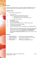
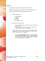
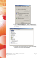
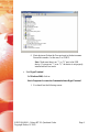
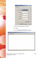
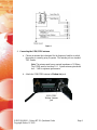
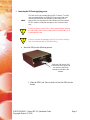
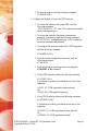
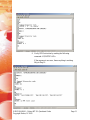
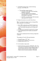
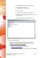
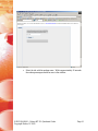
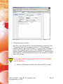
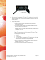
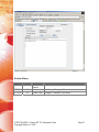
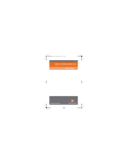
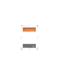
Application Note:
GSM2218AN001
Enfora® MT-GL
Quick Start Guide
Revision 1.02
Enfora, L.P.
661 East 18 Street Plano, Texas 75074-5601
www.enfora.com
th
Objective:
The objective of this document is to provide the user with basic information on how to
configure the modem and verify communication with Enfora’s UDPAPI test server.
Equipment Needed:
In this example the requirements are:
•
•
•
•
•
•
•
•
•
GSM2218 MT-GL
Enfora Serial / Power cable Part number ADT2218 or
a. Connector WAGO 733-112 or equivalent
b. Wire minimum 20 AWG for 20 ft (max) for power.
c. DB9 female connector
Power supply
GSM quad band antenna
GPS 3.3v Active antenna
Computer with one available Serial port or USB-to-serial converter
GSM/GPRS SIM with GPRS data enabled.
An APN (Access Point Name).
Username and Password, if GPRS is operating on a non-transparent network.
Note: If you don’t know the name of the APN you need to use, please contact
your cellular network carrier for that information. Once you have acquired
this information, please complete Application Note GSM0000AN019 –
GSM Network Configuration Worksheet and keep this worksheet for future
reference.
References:
•
•
•
•
GSM2218PB001MAN –
GSM2000PB001MAN –
GSM0107PB001MAN GSM0000AN019 –
Enfora® MT-GL Hardware User Manual
Enfora® Mobile Tracker Software User Manual
Enabler-IIG AT Command Set
GSM Network Configuration Worksheet
GSM2218AN001 – Enfora MT-GL Quickstart Guide
Copyright Enfora, LP 2005
Page 1
Procedures:
1. Configuring the computer and verifying correct communications.
Note: The following examples use Windows 2000 and HyperTerminal. Any
Terminal program should work, using the parameters in Step A.
a. Default Serial Parameters
1.
2.
3.
4.
5.
115200 baud rate
8 data bits
1 stop bit
No Parity
Flow Control = None
b. Determine which Com port to use
1. On older computers, there is usually a built in Com port. This is
normally Com1
2. If you are using a USB-to-serial converter, you will need to
determine which Com port it is installed on.
Note: If the USB-to-serial converter has not been installed, install the
necessary drivers per the instruction supplied by your USB-to-Serial
device. Then leave the device unplugged.
3. Open up the System Properties window. This is done through
the Control Panel > System or right-click on My Computer
and select Properties. Select the Hardware Tab. On Windows
2000 the screen looks like the following:
GSM2218AN001 – Enfora MT-GL Quickstart Guide
Copyright Enfora, LP 2005
Page 2
4. Select the Device Manager button. Expand the Ports section by
selecting the + sign beside Ports. Your window should look like
the following:
5. Plug in the USB-to-Serial converter. The window should change
to show the USB-to-Serial converter installed.
GSM2218AN001 – Enfora MT-GL Quickstart Guide
Copyright Enfora, LP 2005
Page 3
6. Most devices will show the Com port next to the device name.
Record this number. In this case, it is COM12.
Note: Make sure there is no “!” or “X” next to the USB
device. If you see an “!” or an “X,” the device is not properly
installed and will not work.
c. Start HyperTerminal
On Windows 2000, click on:
Start>Programs>Accessories>Communications>HyperTerminal
1. You should see the following screen.
GSM2218AN001 – Enfora MT-GL Quickstart Guide
Copyright Enfora, LP 2005
Page 4
3. Enter a name for the Connection. In this example, the Name is
Enfora Com1.
4. Click OK.
5. The next window that will appear is the Connect To window.
6. Change the Connect Using setting to the Com port that was
determined in Step B.
7. Click OK.
8. The next window is the Port Settings window.
GSM2218AN001 – Enfora MT-GL Quickstart Guide
Copyright Enfora, LP 2005
Page 5
9. Make sure the settings match the example.
10. Click OK.
11. Now the Main Program Window should appear.
GSM2218AN001 – Enfora MT-GL Quickstart Guide
Copyright Enfora, LP 2005
Page 6
d. Terminal Setup Testing.
1. Make sure the cursor is in the main window.
2. Start typing characters.
3. If all settings are correct, you should not see anything happening
in the main window.
4. Jumper Pins 2 and 3 together on the Serial connector.
5. Start typing characters.
6. You should now see what you are typing appearing in the main
window.
7. If this happens, the COM port is configured correctly.
2. MT-GL panel descriptions
a. Front Panel
Power LED
GPS Status LED
Figure 1
SIM Slot
GSM status LED
b. Rear Panel
Figure 2
3. Preparing the Power and Serial Communications Cable
a. Use a factory-built wiring harness with serial data option or build a wiring
harness according to the following schematic.
Note: The Ignition (pin 10) is Optional and is used to sense an
Ignition On event from the vehicle and will cause the modem to
reset if power is removed and reapplied to this input.
GSM2218AN001 – Enfora MT-GL Quickstart Guide
Copyright Enfora, LP 2005
Page 7
Figure 3
4. Connecting the GSM/GPRS antenna
a. Choose an antenna that is designed for the frequency band the in which
the modem is currently going to operate. The antenna jack is a standard
TNC Female.
Note: The antenna must have a nominal impedance of 50 Ohms.
The VSWR must be less than 2.0:1. System antenna gain should
be 0 – 2 dB for optimum performance.
b. Attach the GSM/GPRS antenna to Modem Ant jack.
GSM/ GPRS
Modem Antenna
Jack
GSM2218AN001 – Enfora MT-GL Quickstart Guide
Copyright Enfora, LP 2005
Page 8
5. Inserting the SIM and applying power
Note:
!
!
The SIM card is not provided with the MT-GL device. The SIM
must be obtained from the GSM/GPRS service provider and
must be provisioned by the operator for data and/or voice.
Always take care to protect the SIM. Without the SIM installed,
MT-GL modem is limited to emergency voice communication
only.
Ensure the power to the MT-GL is disconnected before inserting
the SIM card. Failure to do so might result in unusable MT-GL or
a damaged SIM card.
Enfora is not liable for damages to the MT-GL when inserting a
SIM card inside the device. (GSM2218 only).
a. Insert the SIM per the following picture:
Insert the SIM into the SIM
Slot with the notch going into
the slot first, and facing
toward the left side of the
modem.
1. Slide the SIM Lock Door to the left to lock the SIM into the
holder.
GSM2218AN001 – Enfora MT-GL Quickstart Guide
Copyright Enfora, LP 2005
Page 9
b. Install the power cable as shown in the following picture:
1. Hook up the modem to a 12 Vdc power source and apply power.
2. The Power LED should be solid red and the GSM Status LED
should start blinking green.
3. Once the modem attaches to the GSM network, the GSM Status
LED should go solid green. If the GSM Status LED stays
blinking, then there is a problem with the SIM or cellular
reception.
6. Configure the Modem to talk to the Enfora Server
a. Connect and verify Serial connectivity with the Enfora modem.
1. Connect the PC serial connector to the modem serial port.
Note: In the following instructions, <CR> means using the
Enter Key on the keyboard.
2. With HyperTerminal open, hit the Enter key. The modem should
respond with OK. If you do not see this response, double check
your connections and perform the serial loop back test again.
3. Type AT<CR>. The modem should respond with OK. If you
do not see the letters AT, send the following command to the
modem: ATE1<CR>
GSM2218AN001 – Enfora MT-GL Quickstart Guide
Copyright Enfora, LP 2005
Page 10
4. Type ATI<CR> . The modem should respond with Enfora, L.P.
If you get any different response, you are not connected to the
Enfora modem.
b. Configure the Modem to communicate with the Enfora Test Server.
1. The following information will need to be obtained from the SIM
provider. Please refer to GSM0000AN019 – Network
Configuration Worksheet.
3. APN
4. Username and password (If necessary.)
Note: In the following examples, the SIM is for Cingular.
APN = isp.cingular
Username = [email protected]
Password = CINGULAR1
4. Reset the modem to factory defaults:
1. To restore the modem to factory defaults, send the
following command:
AT&F<CR>
2. To write current config to memory, send the following
command:
AT&W<CR>
GSM2218AN001 – Enfora MT-GL Quickstart Guide
Copyright Enfora, LP 2005
Page 11
3. To reset the modem, send the following command:
AT$RESET<CR>
5. Configure the Modem to Access the GPRS network.
1. To inform the modem of the proper APN, send the
following command:
AT+CGDCONT=1,”IP”,”apn”<CR> (substitute the letters
apn for the supplied apn.)
2. To inform the modem of the proper username and
password, (if necessary) send the following command:
AT%CGPCO=1,”username,password”,0<CR> (substitute
the correct username and password)
3. To configure the modem to enable auto GPRS registration,
send the following command:
AT$AREG=2<CR>
4. Store the current configuration to memory, send the
following command:
AT&W<CR>
5. Reset the modem by removing power or sending the
AT$RESET<CR> command.
6. Verify GSM status by sending the following command:
AT+CREG?<CR>
If everything is working, you should receive one of two
responses:
+CREG: 0,1 (GSM registered to home network)
OR
+CREG: 0,5 (GSM registered roaming.)
7. Verify GPRS status by sending the following command:
AT%CGREG?<CR>
If everything is working, you should receive one of two
responses:
%CGREG: 0,1 (GPRS registered to home network)
Or
%CGREG: 0,5 (GPRS registered roaming.)
GSM2218AN001 – Enfora MT-GL Quickstart Guide
Copyright Enfora, LP 2005
Page 12
8. Verify GPRS activation by sending the following
command: AT$NETIP?<CR>
If the response is non-zero, then everything is working.
Skip to Step 10.
GSM2218AN001 – Enfora MT-GL Quickstart Guide
Copyright Enfora, LP 2005
Page 13
9. If AT$NETIP returns all zeros, send the following
command: AT$CGEER<CR>
•
There are three common responses:
• $CGEER: no PDP reject cause (Everything
should be working OK)
• $CGEER: requested service option not
subscribed (APN is incorrect or SIM has not
been enabled for data mode.)
• $CGEER: user authentication failed (username
and/or password is incorrect.)
10. Configure the modem to access the Enfora Server.
Note: To configure the modem for server interoperability,
several things have to be addressed:
•
•
•
Most GPRS configurations are Mobile Originate only.
The mobile modem must initiate a conversation with a
remote server before the remote server can talk to the
modem.
IP addresses are dynamically assigned and can change.
Some IP addresses are NAT and are non-routable IP
addresses.
These issues are addressed with the following configuration
commands.
The examples will use the following information:
•
•
•
Modem ID/name = “MT_Test”
Remote Server IP address = 67.103.214.214
Remote Server IP port = 1721
11. Give the modem a unique name.
•
Send the following command: AT$MDMID=”MT_Test”
This command, combined with the wakeup message, will
allow the server to associate a Public IP address with a
specific modem and create a window of opportunity
where the server can send commands to the modem
GSM2218AN001 – Enfora MT-GL Quickstart Guide
Copyright Enfora, LP 2005
Page 14
12. Configure the modem to talk with a specific server.
•
Send the following command:
AT$FRIEND=1,1,”67.103.214.214”
13. Set the port number
•
Send the following command: AT$UDPAPI=,1721
14. Enable periodic messages (wakeup) to be sent to the server
every 60 seconds
•
Send the following command: AT$WAKEUP=1,1
7. Verifying Server connectivity.
Note: For the following tests, Java Runtime must be installed on the
computer. (To install Java Runtime, please visit the Java website here:
http://www.java.com/en/download/manual.jsp)
a. Start Internet Explorer and enter the following URL:
Http://67.103.214.214/udpapp/
b. Enter the name used in the MDMID command in the box. Select Connect.
GSM2218AN001 – Enfora MT-GL Quickstart Guide
Copyright Enfora, LP 2005
Page 15
c. Select the tab with the modem name. Within approximately 60 seconds
the wakeup messages should be seen in the window.
GSM2218AN001 – Enfora MT-GL Quickstart Guide
Copyright Enfora, LP 2005
Page 16
d. Enter the following command in the command/ data block: ATI
e. Select Write.
f. Verify that you see the following the modem response with Enfora, L.P.
If so, you have successfully configured the modem to talk with the server.
GSM2218AN001 – Enfora MT-GL Quickstart Guide
Copyright Enfora, LP 2005
Page 17
8. GPS Operation and verification
The GPS receiver inside the MT-GL provides power to the pre-amplifier in the
GPS antenna (Active-style) by applying a power of 3.3 Volts to the center
conductor of the RF input to the GPS receiver. If a passive-style GPS antenna
must be used, please verify that it has a DC block installed in order to prevent
shorting to ground. The GPS antenna connector on the MT-GL model is an SMA
female connector. The GPS antenna must be placed in an area where it can have
direct view of the sky.
!
User must disconnect power before connecting the
GPS antenna
a. Install the GPS antenna to the GPS ANT jack on the MT-GL modem.
GSM2218AN001 – Enfora MT-GL Quickstart Guide
Copyright Enfora, LP 2005
Page 18
GPS Antenna
b. After a couple of minutes, the GPS status LED should switch to solid red.
When this happens, the GPS receiver has enough information to track the
current position.
c. Verify GPS operation.
1. From the terminal window, send the following command:
AT$GPSRD=10<CR>
2. The modem should respond with a standard GPRMC message
that looks similar to the following:
$GPRMC,221223.00,A,3301.5080,N,09642.3857,W,000.0,000.0
,230805,05.9,E,A*19
Note: The entry shown in bold is the current GPS status. There
are three possible values here:
•
•
•
A = OK
V = Warning
9 = Enfora Specific response that GPS solution is not valid and
the last known GPS location is being substituted.
3. Here is an example of a GPRMC message without a GPS lock:
$GPRMC,221553.30,V,,,,,,,,,,N*7C
4. The same command can be used in the server app.
GSM2218AN001 – Enfora MT-GL Quickstart Guide
Copyright Enfora, LP 2005
Page 19
Revision History
Date
08/08/05
Rev
1.0
Author
Calvin
French
Description
Initial release.
07/05/06
07/31/06
1.01
1.02
Added step 13 on page 15
Diane ONeil Changed IP address of test server
GSM2218AN001 – Enfora MT-GL Quickstart Guide
Copyright Enfora, LP 2005
Page 20