1
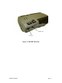
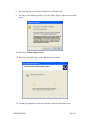
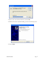
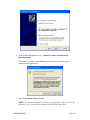
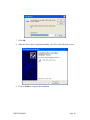
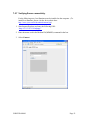
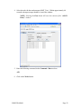
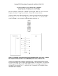
Application Note:
GSM2228AN001
Enfora Mini-MT
Quick Start Guide
ver 1.01
Table of Contents
1
INTRODUCTION ...........................................................................................1
2
GETTING STARTED .....................................................................................2
3
OVERVIEW OF THE ENFORA MINI-MT ......................................................3
3.1
LED INDICATORS ......................................................................................5
3.2
SWITCHES ................................................................................................6
3.2.1
Push To Call (PTC) .........................................................................6
3.2.2
Set Geo-Fence ................................................................................6
3.2.3
User-Defined button ........................................................................6
3.2.4
Volume Buttons ...............................................................................6
3.3
INTERCONNECTIONS ..................................................................................7
3.3.1
USB Connection ..............................................................................7
3.3.2
Headphone Jack .............................................................................7
3.3.3
Speaker ...........................................................................................7
3.3.4
Microphone......................................................................................7
3.3.5
SIM ..................................................................................................7
3.3.6
Battery .............................................................................................8
4
BATTERY REMOVAL / INSERTION / CHARGING ......................................8
4.1
4.2
4.3
REMOVING THE BATTERY ...........................................................................8
INSERTING THE BATTERY............................................................................8
CHARGING THE BATTERY ...........................................................................8
5
SIM CARD INSERTION / REMOVAL............................................................9
6
MINI-MT CONFIGURATION........................................................................10
6.1
DISPATCH NUMBER .................................................................................10
6.2
SMS DESTINATION .................................................................................10
6.3
SET GEO-FENCE.....................................................................................11
6.4
USER-DEFINED BUTTON(S) ......................................................................11
6.4.1
User-definable Button “” .............................................................11
6.4.2
User-definable Button “>” ..............................................................11
6.5
SETTING THE EMERGENCY CALL NUMBER .................................................11
6.6
DIALING THE EMERGENCY CALL NUMBER ..................................................12
7
PC SOFTWARE INSTALLATION ...............................................................13
7.1
MINI-MT USB COMPOSITE DEVICE – DRIVER ...........................................14
7.2
MINI-MT USB TO UART DEVICE – DRIVER INSTALLATION .........................18
7.3
CONFIGURING THE PC AND VERIFYING COMMUNICATIONS. ........................21
7.3.1
Default Serial Parameters .............................................................21
7.3.2
Determine which COM port to use.................................................21
7.4
START HYPERTERMINAL ..........................................................................23
7.5
DEMO CONFIGURATION TO THE ENFORA TEST SERVER ..............................26
7.5.1
Reset the modem to factory defaults .............................................26
7.5.2
Connecting the Mini-MT to the Enfora Test Server .......................26
7.5.3
7.5.4
7.5.5
7.5.6
7.5.7
8
Configure the Modem to Access the GPRS network. ....................27
Verify Registration Status ..............................................................28
Verify GPRS Activation..................................................................28
Configure the modem to access the Enfora Server. ......................29
Verifying Server connectivity. ........................................................31
GPS OPERATION AND VERIFICATION ....................................................34
8.1
VERIFICATION OF GPS LOCK ...................................................................34
8.2
VERIFY GPS OPERATION .........................................................................34
8.2.1
GPS Operation from Terminal .......................................................34
8.2.2
GPS Operation from Enfora Demo Server ....................................35
9
SAFETY INFORMATION FOR WIRELESS DEVICES ...............................36
9.1
9.2
RF EXPOSURE .......................................................................................36
SCIENTIFIC EVIDENCE ON RF EXPOSURE ...................................................37
10
FCC COMPLIANCE STATEMENT ......................................................39
11
PRODUCT SAFETY INSTRUCTIONS .................................................40
REVISION HISTORY..........................................................................................41
Table of Figures
Figure 1 – Mini-MT Features .......................................................................................... 3
Figure 2 – Mini-MT Front View....................................................................................... 3
Figure 3 – Mini-MT Side View ........................................................................................ 4
1 Introduction
This document provides a brief introduction to the Enfora® Mini-MT personal asset
tracking device. This guide will provide basic instructions for configuring a Mini-MT for
evaluation purposes. Advanced features are described in detail in the following reference
documents:
•
•
Enabler-IIG AT Command Set GSM0107PB001MAN
Mobile Tracker AT Command Set GSM2000PB001MAN
GSM2228AN001
Page 1
2 Getting Started
Getting started with the Enfora Mini-MT will require the following:
-
-
Mini-MT
(GSM2228)
USB to mini-USB cable (not supplied)
(CAW-6000-0006)
Activated SIM card (not supplied)
Personal Computer (not supplied)
o Operating Systems: Windows 2000, or XP
o USB port
Enfora Mini-MT USB drivers (available from support website: www.enfora.com,
select Support, select Downloads, Accept, choose GSM)
GSM2228AN001
Page 2
3 Overview of the Enfora Mini-MT
Geo-Fence
User-Defined
Speaker
Volume Up
LED’s
Volume Down
PTC
(Push To Call)
Microphone
Figure 1 – Mini-MT Features
Figure 2 – Mini-MT Front View
GSM2228AN001
Page 3
Headset Jack
USB
Connector
Figure 3 – Mini-MT Side View
GSM2228AN001
Page 4
3.1 LED Indicators
There are four LED’s used to provide status to the user. See Figure 2 for LED
information. The LED functions are defined in the table below.
Power Mode
Hibernate
CALL
ON
GPS
BAT
Yellow
Yellow
Yellow
Red
OFF
Active / Battery Blink when
registering
500mS/1 Sec
OFF
Slow blink
500mS/10Sec
OFF
Blink when
locked
500mS/2 Sec
Blink for
missed call
250mS/2 Sec
Active / Aux
Solid during
call (incoming
or initiated)
Same as above
for Active /
Battery
Low Battery,
less than 20%
Slow Blink
250mS/10Sec
Low Battery,
less than 5%
OFF
Low Battery,
less than 20%
Slow Blink
250mS/10Sec
Low Battery,
less than 5%
OFF
ON solid
Same as above
for Active /
Battery
Fast Blink,
during charge
500mS/2 Sec
OFF when
charged
GSM2228AN001
Page 5
3.2 Switches
3.2.1 Push To Call (PTC)
The Push To Call (PTC) switch allows the user to place a call to a number that has been
programmed, such as the concierge service. To meet GSM specification, pressing the
PTC button with no SIM installed will cause the unit to initiate a “411” call. The
application provider will need to configure the emergency number for its region.
3.2.2 Set Geo-Fence
The switch is used to initiate a geo-fence with a default radius of one-half mile. This
radius may be re-defined by the application provider and is retained in non-volatile
memory. If GPS is not available an error tone will be generated to alert the user that no
geo-fence was set.
3.2.3 User-Defined button
The User-Defined button is a programmable button that can be defined for various
functions. This button could be programmed to generate a call to a number different
from the PTC button, generate a geo-fence with different parameters than the geo-fence
button, send an SMS of the current location to a cell phone, send the current location to
the server, etc.
3.2.4 Volume Buttons
The Mini-MT has two volume buttons for controlling the audio volume level. These
buttons are functional whether in a call or not. The ‘+’ button is used for increasing
volume and the ‘–’ button is used for decreasing volume.
GSM2228AN001
Page 6
3.3 Interconnections
3.3.1 USB Connection
The USB connector is used for charging the battery and for data communication. The
unit will charge from a laptop computer, AC to USB power adapter, or vehicle power to
USB adapter. (See Figure 3)
Data communications with the Mini-MT is also performed through the USB connector.
The USB connection is used to configure or customize the Mini-MT operation. This
connection also is used to provide GPS NMEA data to a mapping or user application.
3.3.2 Headphone Jack
The headphone jack provides the user with the ability to connect a headset (not supplied)
when the speakerphone mode is not desirable. (See Figure 3)
3.3.3 Speaker
An integrated speaker allows the user to make a phone call to the pre-configured dispatch
number when in hands-free mode. The user can adjust the volume to a comfortable level
using the volume up (‘+’) or down (‘-’) buttons.
WARNING
!
The Mini-MT is used in speaker phone or headset use only. Do not
use the device held up to the head . The audio levels and SAR ratings
have not been approved for use in this manner.
3.3.4 Microphone
A built-in sensitive microphone allows the user to communicate with the dispatcher
comfortably at up to 3 feet away for hands-free operation.
3.3.5 SIM
A SIM cardholder is located under the battery on the bottom of the Mini-MT. The SIM
card is required to enable the voice and data communication capabilities of your MiniMT device.
GSM2228AN001
Page 7
3.3.6 Battery
A 1340mA/H Li-Ion battery is supplied with the Mini-MT that will allow operation
without USB power. The Mini-MT battery life varies based on configuration and use of
the Mini-MT.
4 Battery Removal / Insertion / Charging
The Mini-MT is supplied with a 1340mA/H Lithium-Ion rechargeable battery with builtin safety features. The battery should be removed to gain access to the SIM card and for
turning the unit off (shipping or travel). The battery is shipped with a protective cover
over the battery terminals and must be removed before use. The following steps provide
instructions for how to remove or replace a battery.
4.1 Removing the battery
Access to the battery is through the battery door on the bottom of the Mini-MT. Firmly
press the battery cover latch and pull the battery door open. Pull up on the battery using
the thumb latch until the battery releases from the retention clips. Slide the battery away
from the contacts and remove from the Mini-MT.
NOTE: The battery is initially provided with a red protective cover over the
terminals. Remove the protective cover by peeling off of the battery to expose the
terminals. Discard the protective cover after removal.
4.2 Inserting the battery
While the battery cover is removed, insert the battery into the battery compartment with
the contacts aligned with the Mini-MT power contacts. The battery must be inserted into
the battery compartment at a 45-degree angle with the contact end first. Ensure the
contacts of the battery line up with the contacts in the Mini-MT. Push the battery in
towards the contacts and then down firmly until fully seated in the battery compartment.
Replace the battery access door ensuring the latch is locked firmly in place.
4.3 Charging the battery
The Mini-MT must be charged for 12 hours prior to initial use.
Charging your Mini-MT battery may be done using a standard USB cable (optional:
CAW-6000-0006) connected to your desktop personal computer (PC).
GSM2228AN001
Page 8
NOTE: The PC must be turned on or powered up while charging the Mini-MT.
For charging the Mini-MT battery in a vehicle an optional USB to vehicle accessory
power adapter is available (PSA-9000-0002).
NOTE: Many vehicles do not provide power to the accessory jack when the
vehicle ignition is off.
An alternate method for charging using AC power may be performed with the AC power
to USB power adapter (PSA-9000- 0101).
Connect one end of the USB cable to the Mini-MT and the other end to your power
source. The Mini-MT ON LED will be illuminated solid and the BAT LED will flash
while charging.
When the Mini-MT is fully charged the BAT LED will be extinguished and the CALL
LED will be illuminated solidly while connected to a USB power source.
5 SIM Card Insertion / Removal
The Mini-MT requires an activated SIM card to operate on the GSM network. The SIM
card is located under the battery. Remove the battery door and the battery when
accessing the SIM cardholder. (See battery Insertion / Removal section of this document)
Note:
!
The SIM card is not provided with the Mini-MT device. The SIM
must be obtained from the GSM/GPRS service provider and
must be provisioned by the operator for data and/or voice.
Always take care to protect the SIM. Without the SIM installed,
the Mini-MT is limited to emergency voice communication only.
Ensure the power to the Mini-MT is disconnected including
disconnecting from USB cable before inserting the SIM card.
Failure to do so might result in an unusable Mini-MT or a
damaged SIM card.
The tray has a sliding latch for retention of the SIM card. The tray must be opened
before a SIM card can be inserted or removed.
Slide the tray to the “unlatched” position and pivot the tray outward.
Insert (or remove) the SIM card, pivot the tray back into the holder and slide the tray to
the “latched” position. Care should be taken to ensure proper orientation of the SIM card
in the tray before closing.
GSM2228AN001
Page 9
6 Mini-MT Configuration
The Mini-MT must be configured before use. Configuration is performed through AT
commands from a PC computer. A terminal program is required to interface to the MiniMT through the USB cable. HyperTerminal is a terminal program that may be supplied
with your computer operating system and is used in this document for examples.
The Mini-MT drivers must be installed on your computer before proceeding. Refer to
Section 7: Software Installation of this document for driver installation.
6.1 Dispatch Number
The “Dispatch Number” is the phone number the Mini-MT will call when the Push-ToCall (PTC) button is pressed.
To configure the Mini-MT to call phone number “1-214-555-1212” enter the following
command:
AT$DSPATCH=“12145551212” <Enter>
After entering the dispatch number enter: AT&W <Enter> to save. This will ensure that
if the battery is removed the number will not need to be re-entered.
6.2 SMS Destination
The SMS Destination Address is where the Mini-MT would send an SMS text message.
The Mini-MT can store up to five (5) SMS Destination Addresses. The following
example shows how to set an SMS Destination Address:
AT$SMSDA=1, “19875551212”<Enter>
GSM2228AN001
Page 10
6.3 Set Geo-Fence
There are two user-definable buttons on the Mini-MT. The first button is factory defined
to set a geo-fence. Depressing the Geo-Fence button will place a half-mile radius circular
geo-fence around the Mini-MT. When the Mini-MT exits the geo-fence an alert message
will be sent via SMS message to the SMS Destination Address defined in the
AT$SMSDA field. (Messages and alerts can also be sent via GPRS packet data. The
user has the ability to control the IP and port that the packet data is transmitted to)
The factory default configuration of the Mini-MT will not have any SMS Destination
Addresses configured and will not be capable of generating SMS messages for GeoFence events.
6.4 User-Defined button(s)
6.4.1 User-definable Button “”
The Mini-MT “” button is user-definable through the event engine. The default state
is to configure a ½ mile radius geo-fence at the current location.
6.4.2 User-definable Button “>”
The Mini-MT “>” button is user-definable through the event engine. This button
function is not defined from the factory.
6.5 Setting the Emergency Call number
The Mini-MT is capable of dialing an emergency number (AT$EMERNUM) and a
dispatch number (AT$DSPATCH). The default emergency number in the Mini-MT is
“411.” The provider should reconfigure this number to the correct emergency number for
the region the Mini-MT will operate in.
To set the emergency number to “911” enter the following text in the terminal window:
AT$EMERNUM=“911” <enter>
AT&W <enter>
The first command sets the emergency number to 911 and the second commands saves
the setting in the phone to ensure it remains programmed after a master reset (battery
removal).
GSM2228AN001
Page 11
6.6 Dialing the Emergency Call Number
The Mini-MT will allow emergency communications without a SIM card installed.
Initiating an emergency call is done by depressing the PTC button and the “>” button
simultaneously. The ON, GPS, and BAT LED’s will flash in unison. At this point,
momentarily release the PTC button and the CALL LED will flash. Re-depress the PTC
button and confirm the LED’s flash in unison again. Release the “>” and the PTC
buttons.
The Mini-MT will establish a call to the number configured in the AT$EMERNUM
command.
GSM2228AN001
Page 12
7 PC Software Installation
USB drivers are available from the Enfora support website at: www.enfora.com, select
Support, select Downloads, Accept, choose GSM. The USB drivers are compatible
with Windows 2000, and Windows XP operating systems. You only need to connect the
Mini-MT to your computer for configuration, software upgrades, and to view local GPS
data.
The following steps describe the USB Driver Installation process.
NOTE: This is a self-extracting zip file. Save this file to any location on
your hard drive. Double-click the file to extract the twenty (20) included
files. Make a note of the location of these files on your hard drive. You
will need to access these drivers during installation.
Your first step will be double-clicking on the PreInstaller.exe file, which you have just
unzipped. Click on OK after a successful installation.
Windows will find two separate devices.
•
•
Mini-MT USB to UART Device
Mini-MT USB Composite Device
You will need to go through two driver installations in order to install both of these
devices on your PC. Please follow these steps to install the Mini-MT drivers.
GSM2228AN001
Page 13
7.1 Mini-MT USB Composite Device – Driver
1. Plug the Mini-MT into your USB port.
2. You will see the following screen:
3. Click on the radio button next to, “No, not this time.”
4. Click Next.
5. You will see the following screen:
GSM2228AN001
Page 14
6. Click on the radio button next to, “Install the software automatically
(Recommended).”
7. Click Next. You will see the following screen:
GSM2228AN001
Page 15
8. The Operating System will detect the drivers for the Mini-MT.
9. You may see the following screen; if you do, follow Step 10, otherwise proceed to
Step 11.
10. Click the Continue Anyway button.
11. You will see the following screen while the drivers install:
12. You may be prompted to point to the location of the files from this screen:
GSM2228AN001
Page 16
13. Browse to the correct location of the drivers, and click OK.
14. When the drivers have completed installing, you will see the following screen:
15. Click on Finish.
GSM2228AN001
Page 17
7.2 Mini-MT USB to UART Device – Driver Installation
The installation process for the USB to UART Device should automatically start. The
following steps will help guide through the driver installation.
1. You will see the following screen:
2. Click on the radio button next to, “No, not this time.”
3. Click Next. You will see the following screen:
GSM2228AN001
Page 18
4. Click on the radio button next to, “Install the software automatically
(Recommended).”
5. Click Next. You may see the following screen; if you do, follow Step 6,
otherwise proceed to Step 7.
6. Click the Continue Anyway button.
NOTE: You may be prompted to search for a specific driver file. If you see the
following screen, browse to the location of the Mini-MT driver files.
GSM2228AN001
Page 19
7. Click OK.
8. When the drivers have completed installing, you will see the following screen:
9. Click on Finish to complete the installation.
GSM2228AN001
Page 20
7.3 Configuring the PC and Verifying Communications.
NOTE: The following examples use Windows 2000 and HyperTerminal. Any
Terminal program should work, using the parameters in Steps 7.3.1 and 7.3.2.
7.3.1 Default Serial Parameters
Baud Rate:
Data Bits:
Stop Bits:
Parity:
Flow Control:
115200 baud rate
8
1
None
None
7.3.2 Determine which COM port to use
On older computers, there is usually a built in COM port. This is normally COM1
With a USB connection, you will need to determine which COM port it is using.
1. Open up the System Properties window. This is done through the Control
Panel > System or right-click on My Computer and select Properties. Select
the Hardware Tab. On Windows 2000 the screen looks like the following:
GSM2228AN001
Page 21
2. Select the Device Manager button. Expand the Ports section by selecting the ‘+’
sign beside “Ports (COM & LPT).
Your window should look similar to the following:
3. Plug the Mini-MT into your USB port. The window should change to show MiniMT USB to UART Device.
GSM2228AN001
Page 22
Most devices will show the COM port next to the device name. Record this
number. In this example, the Mini-MT device is configured to COM3.
NOTE: Make sure there is no “!” or “X” next to the USB device. If you
see an “!” or an “X,” the device is not properly installed and will not
work.
7.4 Start HyperTerminal
The following configuration steps assume that you are using the Windows XP Operating
System.
Follow these steps:
1. Click Start>Programs>Accessories>Communications>HyperTerminal
You should see the following screen.
2. Enter a name for the connection. In this example, the name is Enfora MiniMT.
3. Click OK.
The next window that will appear is the Connect To window.
GSM2228AN001
Page 23
4. Change the Connect Using setting to the COM port that was determined in
Section 7.3.2, Step 2. For the example we are using COM3.
5. Click OK.
The next window is the Port Settings window.
6. Set the communication port to 115200 bits per second, 8 data bits, no parity, 1
stop bit and no flow control.
7. Make sure the settings match the example.
GSM2228AN001
Page 24
8. Click OK.
The Main Program Window should appear.
9. Type the command ATI in the main window and press the Enter key.
You should see the following screen with the response from the Mini-MT:
The response “Enfora, Inc.” indicates that you are successfully communicating
with the Enfora Mini-MT.
GSM2228AN001
Page 25
7.5 Demo Configuration to the Enfora Test Server
The Mini-MT is capable of communicating with a server. The following steps will guide
you through a configuration that will demonstrate the data communication capabilities to
the Enfora Test Server. A valid SIM card from your carrier is required that allows GPRS
data communications capability.
7.5.1 Reset the modem to factory defaults
To restore the Mini-MT to factory defaults send the following command:
AT&F<CR>
To save the current configuration to memory send the following command:
AT&W<CR>
Reset the modem with the following command:
AT$RESET<CR>
7.5.2 Connecting the Mini-MT to the Enfora Test Server
The following information will be required from the SIM card provider (refer to
GSM0000AN019 – Network Configuration Worksheet):
•
•
•
APN
Username (if required)
Password (if required)
The following examples show how to configure the Mini-MT with a Cingular SIM card
with the following data:
•
•
•
APN=isp.cingular
[email protected]
Password=CINGULAR1
GSM2228AN001
Page 26
7.5.3 Configure the Modem to Access the GPRS network.
De-register the Mini-MT from the network using the following command:
AT+CFUN=0 <CR>
Set the modem with the proper APN (Access Point Name) using the following command:
AT+CGDCONT=1,”IP”,”APN”<CR>
NOTE: Replace the letters “APN” with the APN that was provided to
you by your wireless carrier
Example:
AT+CGDCONT=1, “IP”, “isp.cingular”
Set the username and password with the following command:
AT%CGPCO=1, “<username>,<password>”,0<CR>
NOTE: Substitute the correct username and password, if your cellular
carrier requires a username and password.
Example:
AT%CGPCO=1, “[email protected],CINGULAR1”,0<CR>
Configure the Mini-MT for auto GPRS registration with the following command:
AT$AREG=2<CR>
Save the changes to memory with the following command:
AT&W<CR>
The Mini-MT should be reset to ensure the changes are used. Reset the Mini-MT with
the following command:
AT$RESET<CR>
GSM2228AN001
Page 27
7.5.4 Verify Registration Status
Verify GSM status by sending the following command:
AT+CREG?<CR>
If everything is working, you should receive one of two responses:
+CREG: 0,1 (GSM registered to home network)
OR
+CREG: 0,5 (GSM registered roaming.)
Verify GPRS status by sending the following command:
AT%CGREG?<CR>
If everything is working, you should receive one of two responses:
%CGREG: 0,1 (GPRS registered to home network)
OR
%CGREG: 0,5 (GPRS registered roaming.)
7.5.5 Verify GPRS Activation
Enter the following command to verify that the Mini-MT is activated on the GPRS
network:
AT$NETIP?<CR>
The Mini-MT is activated if it has been assigned an IP address
Example of successful GPRS activation:
at$netip?
$NETIP: "166.217.226.214","066.102.163.231","066.209.010.201"
NOTE: The above IP addresses will be different for each device and
location. Non-zero values indicate a successful GPRS activation.
Example of unsuccessful GPRS activation:
at$netip?
$NETIP: "000.000.000.000", "000.000.000.000", "000.000.000.000"
GSM2228AN001
Page 28
If AT$NETIP returns all zeros, send the following command:
AT$CGEER<CR>
There are three common responses:
$CGEER: no PDP reject cause
(Everything should be working properly)
$CGEER: requested service option not subscribed
(APN is incorrect or SIM has not been enabled for data mode.)
$CGEER: user authentication failed
(username and/or password is incorrect.)
7.5.6 Configure the modem to access the Enfora Server.
To configure the modem for server interoperability, several things have to be addressed:
•
•
•
Most GPRS configurations are Mobile Originate only. The mobile modem must
initiate a conversation with a remote server before the remote server can talk to
the modem.
IP addresses are dynamically assigned and can change.
Some IP addresses are NAT and are non-routable.
These issues are addressed with the following configuration commands.
The examples will use the following information:
•
•
•
Modem ID/name = “MT_Test”
Remote Server IP address = 67.103.214.214
Remote Server IP port = 1721
Give the modem a unique name with the following command:
AT$MDMID=”MMT_Test”
NOTE: This command, combined with the wakeup message, will allow the server
to associate a Public IP address with a specific modem and create a window of
opportunity where the server can send commands to the modem.
GSM2228AN001
Page 29
Configure the modem to talk with a specific server with the following command:
AT$FRIEND=1,1,”67.103.214.214”
Set the port number with the following command:
AT$UDPAPI=,1721
Enable periodic messages (wakeup) to be sent to the server every 60 seconds with the
following command:
AT$WAKEUP=1,1
GSM2228AN001
Page 30
7.5.7 Verifying Server connectivity.
For the following tests, Java Runtime must be installed on the computer. (To
install Java Runtime, please visit the Java website here:
http://www.java.com/en/download/manual.jsp)
1. Start Internet Explorer and enter the following URL:
“http://67.103.214.214/udpapp/”
2. Enter the name used in the Modem ID (MDMID) command in the box.
3. Select Connect.
GSM2228AN001
Page 31
4. Select the tab with the modem name (MMT_Test). Within approximately 60
seconds wakeup messages should be seen in the window.
NOTE: Selecting the Clear button will erase the contents of the “(ASCII
Data):” window.
5. Enter the following command in the Command / Data text box:
ATI
6. Click on the Write button.
GSM2228AN001
Page 32
7. Verify that you see the following modem response showing Enfora, Inc. If so,
you have successfully configured the modem to talk with the server.
GSM2228AN001
Page 33
8 GPS Operation and Verification
The Mini-MT contains an integrated GPS receiver and GPS antenna. For best GPS
performance the unit should be placed in an area where it can have direct view of the sky.
8.1 Verification of GPS Lock
The Mini-MT will provide an indication of successful GPS Lock within approximately
60 seconds when in view of satellites.
The GPS LED will flash yellow when it is receiving a sufficient number of satellites to
provide status. When this occurs, the internal GPS receiver has enough information to
track its current position.
8.2 Verify GPS operation
The Mini-MT GPS status may be obtained locally through the USB connection or
through the GPRS connection to a server. The following steps allow the user to
determine GPS operation through a terminal program and also through the Enfora
Demonstration web server.
8.2.1 GPS Operation from Terminal
From the terminal window, send the following command:
AT$GPSRD=10<CR>
The modem should respond with a standard GPRMC message that looks similar to the
following:
$GPRMC,170513.78,A,3301.465384,N,09642.417298,W,0.0,0.0,011206,,,*06
NOTE: The entry shown in bold is the current GPS status. There are three
possible values here:
•
•
•
A = OK
V = Warning
9 = Enfora Specific response that GPS solution is not valid and the last known
GPS location is being substituted.
GSM2228AN001
Page 34
Here is an example of a GPRMC message without a GPS lock:
$GPRMC,221553.30,V,,,,,,,,,,N*7C
8.2.2 GPS Operation from Enfora Demo Server
The same command can be used in the server application by entering AT$GPSRD=10 in
the Command / Data text box, then selecting Write.
The following screen shot shows the command and the response:
NOTE: The third field is a single character field representing the status of the
GPS reading. There are three valid character for this field and are described
below:
•
•
•
A = OK
V = Warning
9 = Enfora Specific response that GPS solution is not valid and the last known
GPS location is being substituted.
GSM2228AN001
Page 35
9 Safety Information for Wireless Devices
9.1 RF Exposure
!
WARNING
Please read this information before using your wireless device.
Your Mini-MT is a radio transmitter and receiver. It is designed and manufactured not to
exceed the emissions limits for exposure to radio frequency (RF) energy set by the
Federal Communications Commission (FCC) of the U.S. Government. These limits are
part of comprehensive guidelines and establish permitted levels of RF energy for the
general population. These guidelines are based on the safety standards previously set by
the U.S. and international standards bodies. The standards include a substantial safety
margin designed to assure the safety of all persons, regardless of age and health.
The exposure standard for wireless RF devices, such as the Mini-MT, employs a unit of
measurement known as the Specific Absorption Rate, or SAR. The SAR limit set by the
FCC is 1.6W/kg. SAR values at or below that limit are considered safe for the general
public.
Before a wireless RF device is made available for sale to the Public, it must be tested and
certified to the FCC that it does not exceed the SAR limits established by the FCC. Tests
for SAR are conducted using the positions and locations (e.g., at the ear or worn on the
body) as required by the FCC for each device model. The Mini-MT has been tested and
meets the FCC RF exposure guidelines when used as a speakerphone, with a standard
2.5mm headset, or when worn on the body using an approved belt clip. Other uses may
not ensure compliance with FCC RF exposure guidelines.
WARNING
!
GSM2228AN001
To minimize RF exposure, it is strongly recommended that you use a
headset with your Mini-MT or operate it in hands-free mode.
Page 36
9.2 Scientific evidence on RF exposure
The following information, in large part, is excerpted from, or based on, information
provided by the U.S. Food and Drug Administration (FDA) on its website under the
heading “Cell Phone Facts: Consumer Information on Wireless Phones”
(http://www.fda.gov/cellphones/qa.html). The information provided below reflects
scientific evidence available through the end of 2004. Please visit the aforementioned
FDA website (and the other websites mentioned below) for the latest information.
The available scientific evidence does not show that any health problems are associated
with using wireless phones. There is no proof, however, that wireless phones are
absolutely safe. Wireless phones emit low levels of RF while being used. They also emit
very low levels of RF when in the stand-by mode. Whereas high levels of RF can
produce health effects (by heating tissue), exposure to low-level RF that does not produce
heating effects causes no known adverse health effects. Many studies of low-level RF
exposures have not found any biological effects. Some studies have suggested that some
biological effects may occur, but such findings have not been confirmed by additional
research. In some cases, other researchers have had difficulty in reproducing those
studies, or in determining the reasons for inconsistent results.
The FDA and other U.S. government agencies responsible for public health and safety
have worked together and in connection with the World Health Organization (WHO) to
monitor developments and identify research needs related to RF biological effects. It is
generally agreed that further research is needed to determine what effects actually occur
and whether they are dangerous to people. In the meantime, standards-setting
organizations and government agencies are continuing to monitor the latest scientific
findings to determine whether changes in safety limits are needed to protect human
health. In 1996, the WHO established the International EMF Project to review the
scientific literature and work towards resolution of health concerns over the use of RF
technology. The WHO maintains a Web site that provides extensive information on this
project and about RF biological effects and research (www.who.ch/peh-emf).
If there is a risk from using wireless phones—and at this point the scientific evidence
does not demonstrate the existence of such a risk—it is probably very small. But if you
are concerned about avoiding even potential risks, you can take a few simple steps to
minimize your exposure to RF. Since time is a key factor in how much exposure a person
receives, reducing the amount of time spent using a wireless phone will reduce RF
exposure. If you must conduct extended conversations by wireless phone every day, you
could place more distance between your body and the source of the RF, since the
exposure level drops off dramatically with distance. For example, you could use a
headset and carry the wireless phone away from your body or use a wireless phone
connected to a remote antenna.
Some groups sponsored by other national governments have advised that children be
discouraged from using wireless phones at all. For example, the government in the
GSM2228AN001
Page 37
United Kingdom distributed leaflets containing such a recommendation in December
2000. They noted that no evidence exists that using a wireless phone causes brain tumors
or other ill effects. Their recommendation to limit wireless phone use by children was
strictly precautionary, and was not based on scientific evidence that any health hazard
exists. More recently, a report published in January 2005 by the British National
Radiological Protection Board (NRPB) summarized the results of various studies from
2000 to 2004 on the effects of wireless phone use, and concluded that there is no hard
evidence that the health of the public is being harmed by the use of wireless phones, but
that uncertainties remain regarding the risks associated with long-term wireless phone
use. Therefore, the report suggested that a "precautionary or prudent approach" to
reducing RF exposure from wireless phones should be followed until more is known
about these potential risks, including the potential increased sensitivity of children to RF.
The report (NRPB-W65) is available for download at the NRPB website (www.nrpb.org).
Again, the scientific evidence does not show a danger to users of wireless phones,
including children and teenagers. If you want to take steps to lower exposure to RF, the
measures described above would apply to children and teenagers using wireless phones.
Specifically, reducing the time of wireless phone use and increasing the distance between
the user and the RF source will reduce RF exposure.
The FDA scientific staff has reviewed the methodology used by FCC to measure cell
phone RF, and has agreed that it is an acceptable approach, given our current
understanding of the risks presented by cellular phone RF emissions. RF emissions from
cellular phones have not been shown to present a risk of injury to the user when the
measured SAR is less than the safety limits set by FCC (SAR of 1.6 w/kg). The FDA will
continue to monitor studies and literature reports concerning acute effects of cell phone
RF, and concerning chronic effects of long-term exposure to cellular telephone RF (that
is, the risks from using a cell phone for many years). If new information leads FDA to
believe that a change to FCC’s measurement policy may be appropriate, the FDA will
contact the FCC, and both agencies will work together to develop a mutually acceptable
approach.
GSM2228AN001
Page 38
10 FCC Compliance Statement
This device complies with Part 15 of the FCC Rules. Operation is subject to the following
two conditions: (1) This device may not cause harmful interference, and (2) this device
must accept any interference received, including interference that may cause undesired
operation.
This equipment has been tested and found to comply with the limits pursuant to Part 15
Subpart B, Part 22, and Part 24 of the FCC rules. These limits are designed to provide
reasonable protection against harmful interference in an appropriate installation. This
equipment generates, uses, and can radiate radio frequency energy and, if not used in
accordance with instructions, can cause harmful radiation to radio communication.
However, there is no guarantee that interference will not occur in a particular installation.
If the equipment does cause harmful interference in radio and television reception, which
can be determined by turning the equipment on and off, the user is encouraged to try to
correct the interference by one or more of the following measures:
•
•
Increase the separation distance between the equipment and the receiver.
Contact Enfora Technical Support for assistance.
!
GSM2228AN001
Changes or modifications without the express consent of
the manufacturer may void any applicable warranty and
the user’s authority to operate the equipment.
Page 39
11 Product Safety Instructions
!
Please follow all safety instruction outlined below. Failure
to follow these instructions may result in serious personal
injury and/or property damage.
Always obey all applicable regulations in any area where the Mini-MT may be used.
Turn your Mini-MT off by removing the battery in areas where its use is prohibited or
where it may cause interference or danger to anyone.
Use of radio equipment is prohibited in hospitals and may interfere with the use of
medical equipment. Do not use the Mini-MT in hospitals or near medical equipment. The
Health Industry Manufacturers Association recommends that a minimum separation of
six inches (6”) be maintained between a handheld wireless device and a pacemaker to
avoid potential interference with the pacemaker.
When boarding a plane, follow all instructions of the flight crew on the use of wireless
devices. FCC regulations prohibit using your wireless device during any air flight. Turn
off your Mini-MT during flight and at all other times as requested by the flight crew by
removing the battery.
Do not use the Mini-MT in the vicinity of blasting areas where it might interfere with
remote control RF devices used to set off explosives.
Although it is rare, wireless phones can generate sparks. Do not use or store your MiniMT phone around flammable or explosive gas, liquids, chemicals or any other such
materials.
Certain jurisdictions prohibit the use of radio communication equipment while driving to
avoid distractions and prevent accidents. Do not use the Mini-MT while driving in those
jurisdictions. In those other jurisdictions where using a wireless phone while driving is
permitted, use in hands-free mode, avoid using the Mini-MT in heavy traffic or
hazardous weather conditions, and do not take notes, look up phone numbers or engage in
stressful or emotional conversations or any other activity while driving that might divert
your attention from the road.
GSM2228AN001
Page 40
Revision History
Date
08/30/06
12/01/06
02/06/07
Rev
1.00
1.01
GSM2228AN001
Author
D. O’Neil
S. Ollmann
S. Ollmann
Description
Draft
Edits
Added safety, FCC, and RF exposure information
Page 41