1
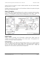
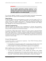
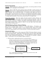
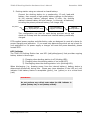
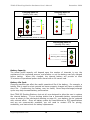
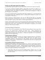
TDAS G5 Docking Station Hardware User’s Manual December 2004 Rev. 2 TDAS G5 Docking Station Hardware User’s Manual December 2004 Table of Contents DTS Support .................................................................................................... 3 Introducing the TDAS G5 Docking Station....................................................... 4 Overview of TDAS G5 Docking Station Features .............................................. 4 Input Range ................................................................................................. 4 Excitation Sources......................................................................................... 4 Sensor Connectors ........................................................................................ 5 Digital Inputs ............................................................................................... 5 Control Panel................................................................................................ 5 Basic Care and Handling ................................................................................. 6 Shock Rating ................................................................................................ 7 Thermal Considerations ................................................................................. 7 Power Management ........................................................................................ 7 Power Consumption....................................................................................... 8 TDAS G5 Docking Station Internal Battery ........................................................ 8 Charging the Battery.................................................................................. 8 LED Indicator ............................................................................................ 9 Battery Capacity.......................................................................................10 Battery Life Cycle .....................................................................................10 Power-up and Power-down Procedures ............................................................11 Communication Features .............................................................................. 11 Communication Method.................................................................................11 Using Multiple TDAS G5 Docking Stations.....................................................11 Auxiliary Signals ..........................................................................................12 Start Record Input ....................................................................................12 Status Output Signal.................................................................................12 Using the Event Input ................................................................................... 13 Appendix A: Control Panel Connector Information ....................................... 14 Suggested Connector Sources........................................................................15 Appendix B: Mechanical Specifications......................................................... 16 Appendix C: Hardware Configuration Specifications..................................... 17 [email protected] ii Rev. 2 TDAS G5 Docking Station Hardware User’s Manual December 2004 DTS Support TDAS systems are designed to be reliable and simple to operate. Should you need assistance, DTS has support engineers worldwide with extensive product knowledge and crash test experience to help via telephone, e-mail or on-site visits. The best way to contact a DTS support engineer is to e-mail [email protected]. Your e-mail is immediately forwarded to all DTS support engineers worldwide and is typically the fastest way to get a response, particularly if you need assistance outside of normal business hours. For assistance by telephone, please go to http://www.dtsweb.com/support.html to find the phone number appropriate for your region of the world. [email protected] 3 Rev. 2 TDAS G5 Docking Station Hardware User’s Manual December 2004 Introducing the TDAS G5 Docking Station The TDAS G5 Docking Station allows for easy installation of a TDAS G5 Data Acquisition System (DAS) into a rugged enclosure for on-board testing applications. Power, communication, and event signals are easily accessible via 2B LEMO connectors on the control panel. Sensors are easily connected via a compact sensor connector panel that can accommodate a variety of user-specified connectors and pin assignments including 1B LEMO and Tajimi. A TDAS G5 DAS can be moved easily from an in-dummy application to an on-board docking station for maximum flexibility of data acquisition resources. Docking stations may be interconnected in a chain to create higher channel-count systems; they may also be interconnected with TDAS PRO racks. This manual discusses the features and options available with the TDAS G5 Docking Station. To identify the specific hardware included with your system, please see your packing list. Overview of TDAS G5 Docking Station Features • • • • • • • • • • • • Built and tested for 100+ G dynamic testing environments. 32 fully-programmable sensor input channels. Internal battery with a capacity of up to one hour. “Smart Charge” circuit helps ensure that the battery receives the proper charge. LED indicator for power and battery status. Power input is protected against reverse current, over-current, and transient over-voltage conditions. 2 volt and 5 volt excitation sources. Ethernet 10/100BaseT/Tx communications allow interconnection with TDAS G5 Docking Stations or TDAS PRO racks. Contact-closure event input with 1000-volt isolation. Rugged, time constant, momentary power switch prevents inadvertent turn off. 16 isolated and protected multi-purpose digital inputs. Integral threaded mounting holes. Please see the DTS web site (www.dtsweb.com) for the latest hardware specifications. Input Range The nominal sensor input range is ±2.5 volts (differential) at a gain of 1. The rated common-mode voltage range is 0.3 to 4.7 volts. Excitation Sources TDAS G5 Docking Stations provide adjustable excitation under software control. Standard excitation voltages are 2 volt and 5.0 volt. (Other factory options are available.) Excitation sources for each channel are individually regulated and current [email protected] 4 Rev. 2 TDAS G5 Docking Station Hardware User’s Manual December 2004 limited (20 mA per channel) to ensure reliable operation even with shorted cables. Recovery time is <1 msec. Excitation sources are not turned on until the software initializes the system during the Real-Time or Collect Data modes. Sensor Connectors DTS supplies TDAS G5 Docking Stations with a variety of connectors and pin assignments. All docking stations have sensor connections as shown below. Please see Appendix C for the specific connectors and pin assignments for your equipment. Diversified Technical Systems, Inc., 2003 All Rights Reserved Sensor Connections Digital Inputs Sixteen isolated, protected, and self-powered contact-closure digital inputs are available via the 26-pin LEMO connector on the control panel. See Appendix A for connector information and pin assignments. Control Panel The control panel on the TDAS G5 Docking Station allows you to connect external power, a contact-closure event signal, digital inputs, and communication signals to your PC and other TDAS G5 Docking Stations or TDAS PRO racks. Please see Appendix A for the connector specifics and pin assignments. [email protected] 5 Rev. 2 TDAS G5 Docking Station Hardware User’s Manual December 2004 Main Power Input • 13-15 VDC Digital Inputs • 16 digital inputs • Event input Momentary Power Switch LED Indicator Communication Connectors (identical) • Ethernet 10/100BaseT/Tx • Status output • Status input • Start record input • Event input TDAS G5 Docking Station Control Panel Basic Care and Handling TDAS G5 Docking Stations are precision devices designed to operate reliably in dynamic testing environments. Though resistant to many environmental conditions, care should be taken not to subject the unit to harsh chemicals, submerge it in water, or drop it onto any hard surface. WARNING: Electronic equipment dropped from desk height onto a solid floor may experience as much as 10,000 Gs. Under these conditions, damage to the exterior and/or interior of the unit is likely. When transporting the unit, treat it as you might a laptop computer and you should have no problems. If a TDAS G5 DAS is not installed in the docking station, we strongly recommend reattaching the clear plastic cap to cover the opening and protect the connector interface on the docking station. When not in use or if shipping is required, we suggest that you always place the unit in the padded carrying case originally provided with your system. [email protected] 6 Rev. 2 TDAS G5 Docking Station Hardware User’s Manual December 2004 WARNING: The 216-position, gold-plated, interface connector on the docking station should be treated with great care. It is through this interface that all signals enter and exit the DAS. Any debris, solvents, or oil (even from fingers) can compromise the integrity of the connections/signals. If you feel the interface connector on your docking station has become contaminated, please contact DTS support before attempting any cleaning procedure. Shock Rating All TDAS G5 vehicle-/sled-mounted systems are rated for and fully tested to 100+ Gs, 12 msec duration, in all axes. TDAS G5 equipment can be mounted directly on a vehicle, sled or other dynamic testing device. Mounting methods and mounting bolt selection should be carefully calculated so as to withstand expected shock loading. (See Appendix B for the mechanical specifications.) Thermal Considerations TDAS G5 systems use extensive power management to minimize heat generation. Since the system draws the most power when armed, running the calibrations and arming as late as possible will minimize self-heating. It is extremely unlikely that excessive heat will ever be an issue in real-world testing applications using TDAS G5 systems. However, if high ambient temperatures, exposure to other heat sources, or severely restricted airflow will cause case temperatures in excess of 50°C (too hot to touch comfortably), the airflow created by a small fan will increase heat transfer by a factor of 3 to 5. Additionally, always shield the units from exposure to direct sunlight. Power Management A good power source is of paramount importance. should be powered from either: Each TDAS G5 Docking Station 1) A high-quality 15-volt power supply with a current rating of at least 2 amps (this would include the TDAS PLUS Distributor and TDAS PLUS Mini Distributor); 2) A fully-charged 12-volt battery with sufficient capacity for the application. When installing power supply systems, always consider voltage drops that may occur due to cables, connectors, power converters, etc. Always remember: • • To ensure the internal battery is fully charged, the minimum input voltage received by the docking station at its power input connector must be ≥13.8 volts. DTS always recommends using an external power source during set-up and check-out. This will ensure that the internal battery is always fully charged. [email protected] 7 Rev. 2 TDAS G5 Docking Station Hardware User’s Manual December 2004 Power Consumption Power off: When connected to sufficient external power, the docking station will draw up to 600 mA for charging the internal battery. Power on: When a TDAS G5 system (docking station and DAS) is initially powered, all sensor excitation sources, signal conditioning electronics, filter circuits and analog-todigital converters are in a shutdown state. The processor and support circuitry are always powered. The processor will remain in a reduced power state when not performing tasks. When the user runs a test set-up, the software automatically energizes the excitation sources and other circuits. The current draw will increase to as much as 1.4 amps when the system is fully armed and powering 32 full-bridge loads. During data collection: Once the system has been armed for data collection, all circuits remain in a full power state until the system finishes storing data. After the data collection routine is complete, the system de-energizes several circuits to minimize power consumption. It takes a maximum of 125 seconds after the end of the data storage window for the system to return to the idle state, which then allows communication and download. TDAS G5 Docking Station Internal Battery Each TDAS G5 Docking Station contains a 2.1 AHr, NiMH battery. This battery can function as the primary power source or as a back-up power source when using external power. The system ensures a smooth transition from external to internal power if the external power source is disconnected or shorted during data collection. Charging the Battery The two most reliable ways to fully charge the TDAS G5 Docking Station’s internal battery are outlined below. (Note that the docking station does not need to be turned on in order to charge the internal battery. It is also not necessary to install a TDAS G5 DAS unit when charging the docking station.) The ON LED is an indicator of battery status. (A discussion of the LED indicator begins on page 9.) 1. Docking station implemented without an external battery: Connect a 15-volt power source to the docking station POWER input. Use this charging set-up for several hours before testing—overnight works well. (The docking station does not need to be turned on in order to charge the internal battery. The docking station may be charged with or without a TDAS G5 DAS installed.) AC power 15 VDC, 2 A Power Supply (non-rugged; off-board) - or – TDAS PLUS Distributor - or – TDAS PLUS Mini Distributor TDAS G5 Docking Station This configuration can also be used during pre-test set-up and check-out to ensure a full charge. [email protected] 8 Rev. 2 TDAS G5 Docking Station Hardware User’s Manual December 2004 2. Docking station using an external on-board battery: Connect the docking station to a crashworthy, 12-volt, lead-acid battery; then connect a high-quality battery charger to the battery. As the external battery charges above 13 volts, the docking station’s internal battery will also charge. In this way, all batteries, including the primary external battery, will charge fully. AC power Battery Charger (e.g., high quality 5 A unit) 12 V SLA Battery (rugged; on-board) TDAS G5 Docking Station This configuration can also be used during pre-test set-up and check-out to keep both the external and internal battery continually charged. DTS-supplied power supplies and distribution units are designed to meet all criteria for proper charging and operation. If you need help determining which set-up is best for your application or if a power supply or charger will meet the power demands, please contact DTS. LED Indicator The TDAS G5 Docking Station has one LED (red/yellow/green) that provides ongoing battery status in three ways: 1) Charging when docking station is off (blinking LED); 2) Charging when the docking station is on (solid LED); 3) Discharging when the docking station is on (blinking LED). When discharging (i.e., drawing power from the internal battery), battery status is determined dynamically during use. Please pay close attention to the LED as it will indicate if the battery status is acceptable (green), low (yellow) or at a critical level (red). WARNING: Do not perform any critical tests when the LED indicator is yellow (battery low) or red (battery critical). [email protected] 9 Rev. 2 TDAS G5 Docking Station Hardware User’s Manual Charging when Off (blinking LED; rate) December 2004 Charging when On (solid LED) (0.4 Hz) >90% >90% >20 - <90% 10 hours (3 Hz) 10 hours >20 - <90% <20% <20% Insufficient external power to charge Discharging when On (blinking LED; rate) (1 Hz) >30 mins Working, BUT recharge! Critical! Battery Capacity The actual useful capacity will depend upon the number of channels in use, the resistance of the connected sensors, and whether or not the battery was fully charged before testing. When fully charged, the internal battery will provide at least 30 minutes of operational power when armed with a full sensor load. Battery Life Cycle Charging practices can affect the useful operational life of the battery. For example, a battery that is used for short periods but never properly charged will have a relatively short life. Conditioning the battery may be useful; three deep-discharge/recharge cycles may help increase battery performance. Most TDAS G5 Docking Stations—but not all—are designed to allow the user to replace the internal battery. If your docking station has a removable battery compartment cover as shown in the mechanical drawing on page 16, your battery can be replaced with minimal effort. Since all battery packs are manufactured to DTS specifications and are not commercially available, you will need to contact DTS for pricing, availability, and instructions for battery replacement. [email protected] 10 Rev. 2 TDAS G5 Docking Station Hardware User’s Manual December 2004 Power-up and Power-down Procedures The momentary switch located on the control panel is used to turn power on and off. To turn on a TDAS G5 Docking Station, press down and hold the switch for 34 seconds until the LED changes status, then release the switch. (The internal powerup sequence takes ~20 seconds to complete.) (Please see the diagrams on page 10 for information on LED status.) To turn off a docking station, press down and hold the switch for 3-4 seconds until the LED changes status, then release the switch. (Please see the diagrams on page 10 for information on LED status.) Before restarting a docking station, wait until all TDAS G5 DAS LEDs go completely dark and then wait 10 seconds more to be sure. An incomplete power-down/power-up cycle can result in errors, so be certain to follow proper procedures. Multiple interconnected TDAS G5 Docking Stations/TDAS PRO rack systems should be powered up at least 10 seconds apart to avoid communication conflicts. (They may be powered up in any order.) Once power-up of all systems is complete, you can then start your TDAS Control software. Communication Features The two 19-pin COM connectors on each TDAS G5 Docking Station control panel allow access to all communication features and status lines. These connectors are functionally identical so you may use either one to connect the communication and trigger cables provided with your system. (Please see Appendix A for the connector specifics and pin assignments.) Communication Method The TDAS G5 Docking Station supports the industry-standard Ethernet 10/100BaseT/ Tx communication method. The docking station itself does not contain an IPaddressable controller; communication is only possible when the docking station contains a TDAS G5 DAS. Communication is enabled after the power-up sequence has completed (~20 seconds). Using Multiple TDAS G5 Docking Stations TDAS G5 Docking Stations can be interconnected in a chain to create higher channelcount systems. In this way, one docking station can act as the main terminal point for a multiple docking-station system. Docking-station-to-docking-station communications are accomplished by using a control cable (RDC-xx-xxxx). The procedure for the making the proper connections is outlined below. • Using either COM port on the first docking station, connect your PC to the docking station using the Ethernet communication cable (REC-xx-xxxx) provided with your system. [email protected] 11 Rev. 2 TDAS G5 Docking Station Hardware User’s Manual • • • December 2004 Then, using a control cable (RDC-xx-xxxx), connect the end marked “MASTER” to the first docking station and the end marked “SLAVE” to either COM port on the second docking station. Using a second control cable, connect the end marked “MASTER” to the open COM port on the second docking station; connect the end marked “SLAVE” to either COM port on the third docking station. Continue connecting the control cables in this manner so that each docking station in the middle of the chain has both a “MASTER” and “SLAVE” cable end connected. The last docking station in the chain will have only the cable end marked “SLAVE” connected; the other COM port will remain open. (Do not connect your PC to the last docking station in the chain.) Note: You may use the open COM port to connect your event input, TDAS PLUS Visual Status Indicator, or other device if desired. Note that TDAS G5 Docking Stations may also be interconnected in this manner with TDAS PRO racks. Auxiliary Signals Additional auxiliary signals are available on either of the 19-pin COM connectors. (Please see Appendix A for the connector specifics and pin assignments.) These signals are: • • Start record input (optically-coupled 0-5 volt signal); Status output (0-5 volt, 20 mA output). Start Record Input The start record input (used only in recorder mode) is used to send a signal to the system to begin recording data independent of any event signal. The desired length of recording time is entered into the TDAS Control software. Once the start record signal is received by the system, data is recorded only for the length of time specified. (An event signal can be used separately to facilitate post-processing of the data.) Care should be taken when using this feature so that the desired event is captured within the data window. (See the TDAS Control software manual for additional information.) Please contact DTS for additional information on how this may be useful in your application. Status Output Signal The status output signal is available for use as an indicator of system status. A typical application would be in an environment where operators may be a substantial distance away from the test equipment, in a control room or other remote location, and desire confirmation from the system that it is armed and healthy prior to testing. The table below describes this function. [email protected] 12 Rev. 2 TDAS G5 Docking Station Hardware User’s Manual December 2004 Status Output Functional Description When the docking station is not armed, the status output is always low (near 0 V), regardless of signals on the event input. The status output will be high (near 5 V) ONLY when: 1. The docking station is armed, AND 2. The docking station is ready to record data (is in circular buffer mode, or has received a start signal in recorder mode), AND 3. The docking station has not received an event signal, AND 4. The docking station’s power status is within acceptable levels. In circular buffer mode, the status output will go high as you arm the system. It will go low when the docking station receives an event signal, any A/D circuit stops functioning, or if the system’s power is outside of acceptable limits. In recorder mode, the status output will remain low until the system is actually recording data. The status output will go high when the docking station receives a start record signal and all other diagnostic checks are within acceptable limits. It will go low when the docking station receives an event signal, the end of the recording time window is reached, any A/D circuit stops functioning, or if the system’s power is outside of acceptable limits. Using the Event Input The TDAS G5 Docking Station contains an isolated, ESD-protected, contact-closure EVENT input. The EVENT input is available through both of the 19-pin connectors and the 26-pin connector. (The specific connector pin assignments can be found in Appendix A.) This input provides a way to use a closure switch in harsh or noisy environments, without negatively affecting the data acquisition system. A software trigger can also be used—please see your TDAS Control software manual for information on how to set a software level trigger. The EVENT input may be used in either of two ways. • • In circular buffer mode, this input actually triggers data collection and is used to mark zero time (T=0). In recorder mode, this input is used to mark T=0 only. WARNING: Do not apply external voltages to the event, communication, status or control output and inputs—this could result in damage to the unit. [email protected] 13 Rev. 2 TDAS G5 Docking Station Hardware User’s Manual December 2004 Appendix A: Control Panel Connector Information 19-pin COM Connectors (EEG.2B.319.CLL) 2 3 4 5 12 1 13 14 11 19 18 15 16 17 6 2 3 9 8 7 (panel view) Suggested cable connector P/N: FGG.2B.319.CLADxx Suggested cable connector P/N: FGG.2B.304.CLADxx Function Internal function only Internal function only 3 4 Shield Start recording input, optically coupled (apply 5 V with respect to pin 16) Common Status output, 5 V via 110 ohm (referenced to common) (+) Status input, optically coupled Ethernet Tx2 (-) Ethernet Tx2 (+) Internal function only Ethernet Rx3 (-) Ethernet Rx3 (+) Ethernet Tx3 (-) Ethernet Tx3 (+) + Event (-) Common for start record and status inputs Ethernet Rx2 (-) Ethernet Rx2 (+) - Event 17 18 19 4 10 1 2 7 8 9 10 11 12 13 14 15 16 1 (panel view) Pin 5 6 4-pin POWER Connector (EEG.2B.304.CLL) [email protected] 14 Pin Function 1 2 + Power - Power Rev. 2 TDAS G5 Docking Station Hardware User’s Manual December 2004 26-pin DIGITAL INPUT Connector (EEG.2B.326.CLL) 3 4 14 1 2 15 16 22 24 17 25 18 5 13 23 12 21 26 11 10 20 19 6 9 8 7 (panel view) Suggested cable connector P/N: FGG.2B.326.CLADxx Pin 1 2 3 4 5 6 7 8 9 10 11 12 13 Function Digital Input 1 Common (1 and Digital Input 2 Digital Input 3 Common (3 and Digital Input 4 Digital Input 5 Common (5 and Digital Input 6 Digital Input 7 Common (7 and Digital Input 8 Digital Input 9 Pin 14 15 16 17 18 19 20 21 22 23 24 25 26 2) 4) 6) 8) Function Common (9 and 10) Digital Input 10 Digital Input 11 Common (11 and 12) Digital Input 12 Digital Input 13 Common (13 and 14) Digital Input 14 Digital Input 15 Common (15 and 16) Digital Input 16 + Event - Event Suggested Connector Sources DTS uses LEMO connectors on the TDAS G5 Docking Station. If you need to purchase connectors, we suggest first going to LEMO directly (http://www.lemo.com/index.html). Their web site and worldwide sales team are very helpful. Should you have difficulty obtaining a specific part number, they can suggest connector variations or alternates and explain options that may be useful for your particular application. Another U.S. source is Alpine Electronics (www.alpine-electronics.com) in San Jose, California. They are a stocking distributor for LEMO and LEMO-compatible connectors. [email protected] 15 Rev. 2 TDAS G5 Docking Station Hardware User’s Manual December 2004 Appendix B: Mechanical Specifications Weight: 2502 grams (LEMO 1B sensor connector panel; TDAS G5 DAS not included) Torque specification for screws (4) fastening connector panel: 1.4 to 1.7 Nm or 12 to 15.6 in-lb Torque specification for screws (4) fastening DAS: 1.6 to 1.8 Nm or 14 to 16 in-lb 3.961 inches 100.6 mm 5.35 inches/135.89 mm Cover for battery compartment (typ) M8 x 1.25 pitch screws; should penetrate docking station 12 mm 8.76 inches/222.504 mm 0.492 inches 12.497 mm 1.969 inches 50.013 mm 2.362 inches 60 mm 9.252 inches/235 mm 0.394 inches 10.008 mm WARNING: The torque specification is critical for proper connection of the TDAS G5 DAS (1.6 to 1.8 Nm or 14 to 16 in-lb) and sensor connector panels (1.4 to 1.7 Nm or 12 to 15.6 in-lb). If the bolts are tightened too little, good contact will not be made; if they are tightened too much, damage may result. Please use a torque wrench if possible. [email protected] 16 Rev. 2