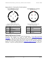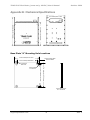
1
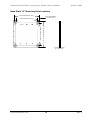
TDAS PLUS Distributor
(power only, 48 VDC)
User’s Manual
October 2004
Rev. 2
TDAS PLUS Distributor (power only, 48 VDC) User’s Manual
October 2004
Table of Contents
DTS Support .................................................................................................... 3
Introducing the TDAS PLUS Distributor........................................................... 4
Overview of power-only TDAS PLUS Distributor Features ............................... 4
Basic Care and Handling ................................................................................. 4
Shock Rating ................................................................................................ 4
Temperature Rating....................................................................................... 5
Power Considerations ..................................................................................... 5
Input Power and Umbilical Calculations ............................................................ 5
Power Connections ........................................................................................ 6
Grounding.................................................................................................... 7
LED Indicators .............................................................................................. 7
Appendix A: Connector Information ............................................................... 8
Suggested Connector Sources......................................................................... 8
Appendix B: Mechanical Specifications........................................................... 9
Base Plate “A” Mounting Hole Locations ............................................................ 9
Base Plate “B” Mounting Hole Locations ...........................................................10
[email protected]
ii
Rev. 2
TDAS PLUS Distributor (power only, 48 VDC) User’s Manual
October 2004
DTS Support
DTS systems are designed to be simple to operate and reliable, but there may be
times when you have questions or you believe the system may not be working
properly. DTS has worldwide support for its products. As part of its support team,
DTS has engineers with extensive product knowledge and crash test experience to help
via telephone, e-mail or on-site visits.
The best way to contact a DTS support engineer is to e-mail:
[email protected]
This e-mail is immediately sent to all DTS support engineers and is the fastest way to
get a reply to your request.
[email protected]
3
Rev. 2
TDAS PLUS Distributor (power only, 48 VDC) User’s Manual
October 2004
Introducing the TDAS PLUS Distributor
TDAS PLUS Distributors function as interface units for all DTS data acquisition products
and serve to simplify hardware integration. They are available in several versions to
meet varying customer requirements around the world.
The power-only TDAS PLUS Distributor provides on-board power for multiple TDAS
products in one rugged unit by eliminating the need for multiple power supplies or
batteries.
Overview of power-only TDAS PLUS Distributor Features
•
•
•
•
•
Built and tested for 100+ G dynamic testing environments.
Provides power for up to nine TDAS PRO racks, TDAS G5 Docking Stations or
other TDAS equipment in any combination.
Power input is protected against reverse current, over-current, and transient
over-voltage conditions.
LED indicators for power input and output.
Integral mounting flanges for ease of use.
Basic Care and Handling
The TDAS PLUS Distributor is designed to operate reliably in 100+ G dynamic testing
environments. Though resistant to most environmental conditions, care should be
taken not to subject the unit to harsh chemicals, submerge it in water, or drop it onto
any hard surface.
When transporting the unit, treat it as you might a laptop computer and you should
have no problems. We suggest that you always place the unit in the padded carrying
case originally provided with your unit when it is not in use.
WARNING:
Electronic equipment dropped from desk height onto a solid
floor may experience as much as 10,000 Gs. Under these
conditions, damage to the exterior and/or interior of the unit is
likely.
Shock Rating
All TDAS systems are rated for and fully tested to 100+ Gs, 12 mS duration, in all
axes. TDAS equipment can be mounted directly on a vehicle, sled or other dynamic
[email protected]
4
Rev. 2
TDAS PLUS Distributor (power only, 48 VDC) User’s Manual
October 2004
testing device. Mounting methods and mounting bolt selection should be carefully
calculated so as to withstand expected shock loading. (See Appendix B for the
mechanical specifications.)
Temperature Rating
Your system has been tested for full functionality with a case temperature of 70°C.
The actual case temperature will be affected by three primary factors:
1) Output power,
2) Ambient temperature and airflow, and
3) Sunlight exposure.
Always shield the units from exposure to direct sunlight and avoid situations where
airflow is significantly restricted. If two or more of the primary factors will cause high
case temperatures, additional airflow across the units will significantly reduce case
temperature.
The main power converters are mounted to the base plate of the unit. Bolting the unit
to a structure with significant thermal mass will reduce the operating temperature
through the heat sinking effect.
When in doubt, measure the case temperature and take whatever steps are necessary
to reduce the case temperature to less than ~60°C for safe operation.
Power Considerations
A good power source is of paramount importance. The TDAS PLUS Distributor should
be powered from a high-quality power source with output voltage and current ratings
appropriate for the installation.
Each vertical column of three connectors is driven by a separate power converter that
can provide 400 W at 13.8 volts. (Connecters 1-1, 1-2 and 1-3 share the same
converter, connectors 2-1, 2-2, and 2-3 share another converter, etc.) For maximum
reliability, TDAS systems should be connected from left to right and then top to
bottom. For example, when connecting four systems, use ports 1-1, 2-1, 3-1 and 1-2.
The power-only TDAS PLUS Distributor does not contain an internal back-up battery.
Input Power and Umbilical Calculations
The TDAS PLUS Distributor contains high-efficiency power conversion circuitry with a
wide input range and a well regulated 13.8 volt output. With an appropriate umbilical
and off-board power supply, the system supplies optimal power for TDAS systems
without having to worry about variable voltage drop through the umbilical.
It is very important that you choose a power supply and umbilical wiring carefully to
ensure there is at least 36 volts at the input connector of the TDAS PLUS Distributor
under all circumstances. Umbilical cables have resistance that depends upon the con-
[email protected]
5
Rev. 2
TDAS PLUS Distributor (power only, 48 VDC) User’s Manual
ductor diameter and increases with length.
the use of larger conductors.
October 2004
Longer umbilical cables typically require
The input power required is directly related to the load placed on the outputs and the
applied input voltage. DTS recommends the following strategy to ensure success:
1. Determine the worst-case DAS load. For TDAS PRO equipment, assume 1 amp
per module or rack. For each TDAS G5 DAS/Docking Station system, assume
2 amps per system.
2. Calculate the TDAS PLUS Distributor input current. The input current requirement is as follows:
Input current = ((total DAS current) * (13.8/Vin)*1.25)
where
1.25 is the compensation for conversion loss, and
Vin = voltage at the input connector of the TDAS PLUS Distributor (after
cable loss).
3. Calculate the required power supply and wiring to maintain at least 36 volts at
the unit’s POWER IN connector. (Assume 40 volts at the input connector.)
Example: Three eight-slot TDAS PRO racks and 24 SIMs (192 channels)
•
•
•
Worst-case DAS current = 27 amps
Input current at 40 volts = (27) * (13.8/40)*1.25 = 11.64 amps
Assume that a 100 m umbilical is required. Fourteen-gage wire has a
nominal resistance of ~0.85 ohm per 100 m. Since current flows through
two wires (+ and -), the total resistance will be ~1.7 ohms. The worstcase voltage drop will be 11.64 amps * 1.7 ohms = 19.79 volts.
In this example, a reasonable solution would be to use a 60 volt power
supply rated for at least 12 amps with a 100 m, 14-gage umbilical.
4. Please contact DTS if you require assistance.
Power Connections
Depending on the customer’s specifications for the unit, it may be provided with a
power-in cable or the cable connector only. (Please see Appendix A for connector
information and pin-outs.) Cables (RPP-xx-xxxx) from the POWER OUT connectors to
other TDAS equipment can be supplied by DTS or the customer may choose to
assemble these on-site.
Power connections should be made as follows:
1. Connect the TDAS PLUS Distributor’s power supply to the POWER IN connector
on the unit.
2. Connect a power cable (RPP-xx-xxxx) from POWER OUT port 1-1 to the TDAS
equipment of choice.
[email protected]
6
Rev. 2
TDAS PLUS Distributor (power only, 48 VDC) User’s Manual
October 2004
3. Continue in this manner, from left to right then top to bottom, until all
equipment has been connected.
Grounding
In addition to providing reliable power conversion for TDAS systems, the TDAS PLUS
Distributor also provides a means for grounding the entire data acquisition system and
the test vehicle. The enclosure of the TDAS PLUS Distributor is connected to pin D of
the power input connector (Amphenol MS3474L14-4P) and to pins 3 and 4 of each
power output connector (LEMO ECG.2B.304.CLL).
(Please see Appendix A for
connector information and pin-outs.) Special steel washers are bonded to the mounting flanges of the TDAS PLUS Distributor with conductive epoxy to help facilitate
proper grounding.
DTS strongly recommends that the test vehicle or sled be connected to earth ground.
One easy way to do this is to attach a trailing ground cable to the TDAS PLUS
Distributor’s power input connector or one of the mounting bolts.
Additionally, it is very important that the enclosures of all TDAS equipment be
grounded to each other and the test vehicle or sled structure. This will minimize any
risk of data noise due to high-current transients from sources such as vehicle battery
shorts or air bag squib shorts. Bolting the units to the vehicle or mounting structure
will ordinarily provide proper grounding.
DTS recommends checking continuity
between the enclosures of each unit to confirm resistance readings of <1 ohm.
If the installation does not permit bolting the TDAS PLUS Distributor and connected
TDAS systems to a common ground, either connect ground wires between the various
enclosures or use grounding power cables available from DTS.
Please contact DTS if you have any questions regarding proper methods to ground the
system.
LED Indicators
The power-only TDAS PLUS Distributor has four LEDs that provide ongoing power
status information. There is one LED for POWER IN and three LEDs for POWER OUT
(one per vertical power bank). These LEDs will either be on (green) or off.
A green POWER IN LED indicates only that there is power to the unit, but not that it is
sufficient or within acceptable levels. Green POWER OUT LEDs indicate that there is
both sufficient input and output power levels.
[email protected]
7
Rev. 2
TDAS PLUS Distributor (power only, 48 VDC) User’s Manual
October 2004
Appendix A: Connector Information
4-pin POWER IN connector
(Amphenol MS3474L14-4P)
4-pin POWER OUT connectors
(ECG.2B.304.CLL)
A
D
1
4
2
3
B
C
(panel view)
(panel view)
Suggested cable connector P/N:
MS3476L14-4S/97-3057-1008-1 (621)
Suggested cable connector P/N:
FGG.2B.304.CLADxx
Pin
Function
Pin
Function
A
+ VDC
1
+ Power
B
No connection
2
- Power
C
- VDC
3
Enclosure
D
Enclosure
4
Enclosure
Suggested Connector Sources
DTS uses LEMO connectors on the TDAS PLUS Distributor. If you need to purchase
connectors, we suggest first going to LEMO directly (http://www.lemo.com/
index.html). Their web site and worldwide sales team are very helpful. Should you
have difficulty obtaining a specific part number, they can suggest connector variations
or alternates and explain options that may be useful for your particular application.
Another U.S. source is Alpine Electronics (www.alpine-electronics.com) in San Jose,
California. They are a stocking distributor for LEMO and LEMO-compatible connectors.
[email protected]
8
Rev. 2
TDAS PLUS Distributor (power only, 48 VDC) User’s Manual
October 2004
Appendix B: Mechanical Specifications
5.8 inches/147.3 mm
7.07 inches/179.6 mm
8.55 inches/217.2 mm
Base Plate “A” Mounting Hole Locations
7.78 inches/197.61 mm
0.375 inches diam
9.5 mm diam
7.04 inches/178.82 mm
0.74 inches
18.8 mm
7.6 inches/193.04 mm
7.15 inches/181.61 mm
0.45 inches
11.43 mm
0.24 inches thick
6.1 mm thick
[email protected]
9
Rev. 2
TDAS PLUS Distributor (power only, 48 VDC) User’s Manual
October 2004
Base Plate “B” Mounting Hole Locations
7.78 inches/197.61 mm
0.375 inches diam
9.5 mm diam
6.693 inches/170 mm
7.78 inches/197.61 mm
6.693 inches/170 mm
0.24 inches thick
6.1 mm thick
[email protected]
10
Rev. 2