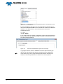
1
Pipe Detection PDS2000 Version 1.0.3 February 2014 Teledyne RESON B.V. Stuttgartstraat 42- 44 3047 AS Rotterdam The Netherlands Tel.: +31 (0)10 245 15 00 www.teledyne-reson.com Amendment Record Sheet Rev. Date Reason for Modifications 1.0.3 06/02/2014 Chapter added five point detection logging 1.0.2 05/02/2014 Chapter added Reson 7K five points detection 1.0.1 04/01/2013 Chapter added about use of dual head 1.0.0 03/12/2012 First version of the Pipe Detection Manual. Contents 1 Introduction 1 1.1 Pipe Detection ........................................................................................................ 1 2 Quick Guide 3 2.1 Introduction ............................................................................................................. 3 2.2 Steps ....................................................................................................................... 3 3 Setup Vessel Configuration 5 3.1 Introduction ............................................................................................................. 5 3.2 Vessel Configuration .............................................................................................. 5 3.2.1 Equipment ..................................................................................................... 5 3.2.2 Tools ............................................................................................................. 6 3.2.3 Logging ......................................................................................................... 7 4 Acquisition 9 4.1 Introduction ............................................................................................................. 9 4.2 3D View – Online .................................................................................................. 10 4.2.1 Pipe Detection Parameters ......................................................................... 10 4.2.2 Pipe Route Logging .................................................................................... 11 4.3 Sonar Steering ...................................................................................................... 11 4.3.1 Activate Sonar Steering .............................................................................. 11 5 Editing 13 5.1 Introduction ........................................................................................................... 13 5.2 Create Pipe Route File ......................................................................................... 14 5.3 Editing Pipe Route ................................................................................................ 15 5.3.1 Delete .......................................................................................................... 15 5.3.2 Insert ........................................................................................................... 16 5.3.3 Editing in the Multibeam Area Editing + Profile View .................................. 17 5.3.4 Editing in Multibeam Area Editing View ...................................................... 18 6 Pipe Detection Parameters 19 6.1 Introduction ........................................................................................................... 19 6.2 Parameters ........................................................................................................... 19 6.2.1 Pipe In Sway Detections ............................................................................. 19 6.2.2 Pipe Parts Creation ..................................................................................... 21 6.2.3 Pipe Route Creation .................................................................................... 22 7 RESON 7K Five point detection 23 7.1 Introduction ........................................................................................................... 23 7.2 Procedure ............................................................................................................. 23 PDS2000 - Pipe Detection Contents i 7.2.1 Application type .......................................................................................... 23 7.2.2 Driver selection ........................................................................................... 24 7.2.3 Add Pipe Detections layer .......................................................................... 27 7.3 Five Point detection logging ................................................................................. 29 8 Appendix – Dual Head 33 8.1 Introduction .......................................................................................................... 33 8.2 Acquisition ............................................................................................................ 34 8.3 Editing .................................................................................................................. 35 ii Contents PDS2000 - Pipe Detection Figures Figure 3-1 Figure 3-2 Figure 3-3 Figure 3-4 Figure 4-1 Figure 4-2 Figure 5-1 Figure 5-2 Figure 5-3 Figure 5-4 Figure 5-5 Figure 5-6 Figure 5-7 Figure 5-8 Figure 6-1 Figure 6-2 Figure 6-3 Figure 7-1 Figure 7-2 Figure 7-3 Figure 7-4 Figure 7-5 Figure 8-1 Figure 8-2 Part of the Equipment page with the Device Configuration for the RESON SeaBat 7k selected .......................................................................................................................... 6 Part of the Pipe Detection page in the Tools Page ............................................................. 6 The Pipe Detection page with the pipe detection parameters ............................................ 7 Part of the Logging page with the Pipe Route Format selected .......................................... 7 3D View – Online with multibeam data and two pipes detected ....................................... 10 The parameters for the sonar steering in the Pipe Routes Computation .......................... 11 Multibeam Area Editing view with a pipe route and a Profile view .................................... 13 Multibeam Area Editing view in the Pipe Detection mode and a Profile view with a created pipe route............................................................................................................. 15 Part of the Multibeam Area Editing view where a edit circle will be deleted ..................... 16 Part of the Profile view where the edit circle will be deleted ............................................. 16 Part of the Multibeam Area Editing view with left a new edit circle will be inserted and right where it is inserted ............................................................................................. 16 An edit circle that is not in the right position ...................................................................... 17 In the Profile view the edit circle is dragged to the right position ...................................... 17 Edit pipe option in the Multibeam Area Editing – Standard view ...................................... 18 Pipe detections with a good Maximum Free Span Filter value ......................................... 20 No pipe detections found in free span area because of a too small Maximum Free Span Filter value................................................................................................................ 20 Left a good and right a too small Detected Threshold Filter ............................................. 21 Application type ................................................................................................................. 23 Five point detections in 3D View – Online ......................................................................... 29 Settings Five points detection SUI .................................................................................... 29 Five point detection ASCII file. .......................................................................................... 31 Five point detection ASCII file with two pipes. .................................................................. 32 3D View – Online with two sonars used for pipe detection ............................................... 34 Pipe Detection mode in the Multibeam Area Editing view with two sonars and for the same pipe two pipes detected ..................................................................................... 35 PDS2000 - Pipe Detection Figures iii 1 Introduction 1.1 Pipe Detection This manual is the manual about the pipe detection in PDS2000. Before the pipe detection will be explained, a brief explanation is given about the different steps to come to a pipe detection. After the quick guide the setup in PDS2000 will be discussed, where only the relevant setup issues will be explained which are related to the pipe detection. When the setup is done the pipe detection can be started in the Acquisition and later on processed in the Editing. For both modules the relevant issues will be explained. The most important chapter will be the explanation of the pipe detection parameters and how they can be used to detect a pipe. In a separate chapter it is described how to setup a five points detection layer for a Reson 7K sonar. In the appendix is explained how at the moment PDS2000 works with two sonars detecting the same pipe. This manual will only explain parts related to the pipe detection. For other information about PDS2000 see the PDS2000 User Manual (the file PDS2000 User Manual.pdf in the folder ‘manuals’). This manual is also available as a HTML Help file and can be opened with F1 or with Help > Help Topics from the menu bar. PDS2000 - Pipe Detection Introduction 1 2 Quick Guide 2.1 Introduction This chapter will give the steps the operator has to follow to get the pipe detection running in the Acquisition and Editing, and how he can process the pipe detection to get the final pipe route file. 2.2 Steps Next to a normal setup of the vessel configuration for a survey the following steps have to be done in the vessel configuration to get pipe detection and sonar steering working: For the sonar steering add for each sonar a Device Configuration device driver to the Equipment list (see page 5). Enable the Pipe Detection in the Pipe Detection tab of the Tools page (see page 6). Enable the pipe route logging in the Logging page (see page 7). In the Acquisition: Open the 3D View – Online to display the pipe detection (see page 10). Open the Pipe Detection tab in the Tools Settings to set the pipe detection parameters (see page 10). In the Editing: Open the Multibeam Area Editing view in the Pipe Mode (see page 13). Enable the pipe detection if it is not enabled yet (see page 14). Modify pipe detection parameters if needed (see page 19). Create a pipe route file (see page 14). Edit the created pipe route (see page 15). PDS2000 - Pipe Detection Quick Guide 3 3 Setup Vessel Configuration 3.1 Introduction Next to the standard setup of the vessel configuration for a multibeam or multi-purpose survey some extra settings have to be set specific for the pipe detection. 3.2 Vessel Configuration The extra settings in the vessel configuration are: When the multibeam system is a RESON SeaBat 7k sonar, PDS2000 can steer the sonar with a horizontal or flex steering. Before this can be done a specific device has to be added in the Equipment page (see below). In the Tools page in the Pipe Detection tab the pipe detection has to be enabled. When this is done automatically the right pipe computations will be added. The parameters of this computations will be listed in the page (see page 6). In the Logging page the pipe route logging has to be selected when the user wants to log the detected pipe route(s) (see page 7). 3.2.1 Equipment In the Equipment page, next to all the standard device drivers needed for a multibeam survey, for each RESON SeaBat 7k system a driver has to be installed to make the horizontal or flex steering possible for that system. Select in the Group ‘Device Configuration’ the device driver RESON SeaBat 7k and add this to the Equipment list. PDS2000 - Pipe Detection Setup Vessel Configuration 5 Figure 3-1 Part of the Equipment page with the Device Configuration for the RESON SeaBat 7k selected It is also possible by selecting in the Group ‘Multibeam (All Options)’ the device driver RESON SeaBat 7k. Here all relevant drivers for the RESON SeaBat 7k are added at once. One of the drivers is the Device Configuration driver. 3.2.2 Tools In the Tools page of the vessel configuration a tab for the pipe detection is present. When this Pipe Detection page is opened for the first time it will look like as displayed below. Figure 3-2 6 Setup Vessel Configuration Part of the Pipe Detection page in the Tools Page To get pipe detection active in PDS2000 check the option Enable pipe detection and the default pipe detection parameters will be displayed. There will be only one set of pipe detection parameters. So when two sonars are used the parameters are valid for both sonar systems. PDS2000 - Pipe Detection Figure 3-3 The Pipe Detection page with the pipe detection parameters The explanation of the parameters will be described in the chapter Pipe Detection Parameters on page 19. 3.2.3 Logging In the Logging page next to the normal file formats a pipe route format can be selected. When this option is selected for each detected pipe route a pipe route file (track guidance route file) with a default filename will be created. The file name is based on the PDS2000 logging format as defined in the Log Files page of the Project Configuration. Figure 3-4 PDS2000 - Pipe Detection Part of the Logging page with the Pipe Route Format selected Setup Vessel Configuration 7 4 Acquisition 4.1 Introduction In this chapter the pipe detection in the Acquisition will be discussed. In the 3D View – Online the pipe detection can be monitored. The settings for the pipe detection can be modified with the parameters in the Tools Settings which is identical with pipe detection page in the Tools page (see page 6). When as multibeam system a RESON SeaBat 7k sonar is used, the sonar steering can be done from PDS2000 with the aid of the pipe detection (see page 11). PDS2000 - Pipe Detection Acquisition 9 4.2 3D View – Online In the Acquisition the 3D View – Online has to be opened to view the results of the pipe detection. Figure 4-1 3D View – Online with multibeam data and two pipes detected The Pipe Detections Layer in the 3D View – Online is only for the visualization of the pipe detection data. The pipe detection parameters can be set in the Tools page (see below). When a second sonar is used a Multibeam and a Pipe Detections Layer for that second sonar have to be added to the 3D View – Online before the pipe detection with that sonar can be visualized in the view. 4.2.1 Pipe Detection Parameters To get pipe detections, pipe parts and pipe routes in the view pipe detection parameters have to be defined. Select the menu item Tools > Tools Settings and select the Pipe Detection tab to get access to the parameters. For a detailed explanation of the pipe detection parameters see chapter Pipe Detection Parameters on page 19. 10 Acquisition The pipe detection parameters are only accessible in the Tools page when the logging is off. The parameters are not available in the pipe detection computations in the Raw Data view. PDS2000 - Pipe Detection 4.2.2 Pipe Route Logging See page 7 for more information about the pipe route format. In the PDS2000 log data file only the pipe detection parameters, the pipe detections and the pipe parts will be stored. The pipe route(s) as displayed in the 3D View – Online is/are not stored; enable the pipe route format in the Logging page to create one or more pipe route files. The Logging page can be opened with in the toolbar or with the menu item Logging > Logging Settings. 4.3 Sonar Steering To get the sonar steering operational in PDS2000 the device driver for the Device Configuration has to be added to the Equipment (see page 5) and one of the sonar steering’s has to be enabled in the Pipe Routes Computation (see below). 4.3.1 Activate Sonar Steering The sonar steering can be activated and set in the Pipe Routes Computation. In the Acquisition the computation can be opened in the Raw Data view or in menu item Edit > Computations under the User Computations. Figure 4-2 Computation The parameters for the sonar steering in the Pipe Routes Select the item Pipe Route Sonar Steering and select the type of steering ‘Horizontal Steering’ or ‘Flex Steering’ and tweak the two settings Pipe Route Steering Delay and Pipe Route Steering Difference to get the best performance for the sonar steering. At the start of the survey the settings for the horizontal or flex steering has to be set in the RESON SeaBat 7k. After the settings are set manually, PDS2000 will not change the settings during the time of the delay. The delay is defined as the number of patches of 25 pings. At the moment the size of the patch cannot be modified. For instance, if the Pipe Route PDS2000 - Pipe Detection Acquisition 11 Steering Delay is set on 5 then PDS2000 will wait until the 5*25 pings is surveyed before, if necessary, the settings for the horizontal or flex steering are changed. The parameter Pipe Route Steering Delay is only relevant when the settings for the steering are manually changed in the RESON SeaBat 7k. For the general steering corrections detected by PDS2000 the delay is not used. The reason that PDS2000 wants to changing the settings for the steering is when the difference (in degrees) between the horizontal steering or angle of the flex steering and the angle of the detected pipe in PDS2000 is more than the Pipe Route Steering Difference as set in the Pipe Routes Computation. When more pipes or pipe parts are detected PDS2000 will take an average of the pipe (parts) positions to calculate a steering angle. The pipe with the best quality of detections will have a bigger weight in the average calculation. With this situation it is possible that the steering is not always on the main pipe which has to be tracked. When horizontal steering is selected PDS2000 will change the horizon steering in the RESON SeaBat 7k sonar when PDS2000 calculates that it is needed. The Flex mode has to be selected in the RESON SeaBat 7k, before the flex steering can work. 12 Acquisition When flex steering is selected PDS2000 will change the angle of the center beam of the flex mode in the RESON SeaBat 7k sonar when PDS2000 calculates that it is needed. The width of the flex mode and the settings of the flex mode will not be changed. PDS2000 - Pipe Detection 5 Editing 5.1 Introduction In this chapter the pipe detection in the Multibeam Area Editing view will be discussed. When the pipe route is created it is possible to edit the pipe in the view (see page 15). The created and edited pipe route will be stored in the project. Click on the Pipe Detection Mode ( ) above the left pane of the Multibeam Area Editing view to open the pipe detection mode for the view. When the pipe detection mode is selected a Profile view is added to the layout of the Editing. Figure 5-1 Multibeam Area Editing view with a pipe route and a Profile view When the pipe detection mode was enabled in the Vessel Configuration (see page 6) before the logfiles were logged then the pane in the Pipe Mode will automatically be filled with the parameters as used during the PDS2000 - Pipe Detection Editing 13 logging. When the pipe route is also logged it can be selected as route file at the top of the pane. When in the Acquisition no pipe detection was done then in the left pane the option Enable Pipe Route Detection has to be checked. When checked the pipe detection computations will be created and the default pipe detection parameters becomes available. With this parameter settings a pipe route file can be created. Modify the parameters in the pane to get the best pipe detection (see page 19) and create a (new) pipe route from the pipe detections and pipe parts (see below). 5.2 Create Pipe Route File After the pipe route(s) is/are detected a pipe route file has to be created. The following steps have to be done: Select the pipe route parts The user can select which pipe route parts have to be used for the pipe route file. If all the pipe route parts have to be used click on or click on to select in the view one by one the pipe route parts for the pipe route file. To select interactive, the option has to be checked. The selected pipe route part will be colored red. When a wrong selection is made click on the wrong selected pipe route part again and it gets the pipe route color again. Click on when all the selected pipe route parts have to be deselected. Select or create a pipe route file Select an existing pipe route file at the top of the pane or create a new pipe route with . The data in the existing pipe route file will be overwritten. To avoid to have a lot of points in the pipe route file, check the option Resample route using interval and enter an interval to get one point per interval. Create the pipe route file Click on to start the creation of the pipe route file. The created pipe route file will be stored in the project. After the file is created it is possible to edit the pipe route (see below). 14 Editing PDS2000 - Pipe Detection 5.3 Editing Pipe Route After the pipe route file is created uncheck the option and only the edit circles of the created pipe route are visible (see below). Figure 5-2 Multibeam Area Editing view in the Pipe Detection mode and a Profile view with a created pipe route In the Multibeam Area Editing view the edit circles of the pipe route can be moved, deleted or inserted. There are two methods of editing the edit circles; in the Multibeam Area Editing view with the use of the Profile view (see below) or in the Multibeam Area Editing view itself (see page 18). The first method is the easiest way to edit the pipe route. 5.3.1 Delete If the detected pipe location is wrong and has to be deleted, click with the right mouse button on the edit circle and select the option ‘Delete’. This can be done in Multibeam Area Editing view and in the Profile view. PDS2000 - Pipe Detection Editing 15 Figure 5-3 deleted Part of the Multibeam Area Editing view where a edit circle will be Figure 5-4 Part of the Profile view where the edit circle will be deleted 5.3.2 Insert When the gap between two edit circles is too big to define the pipe route, extra circles can be inserted. Click with the right mouse button on the location in the pipe where a new edit circle has to be inserted and select the option ‘Insert’. This can only be done in the Multibeam Area Editing view. Figure 5-5 Part of the Multibeam Area Editing view with left a new edit circle will be inserted and right where it is inserted 16 Editing PDS2000 - Pipe Detection 5.3.3 Editing in the Multibeam Area Editing + Profile View In the Multibeam Area Editing view the edit circle can be selected and in the Profile view the circle can be moved to the right position. Double click on an edit circle and a profile is drawn over the select edit circle and in the Profile view the edit circle of the pipe route is displayed. In the Profile view the red circle can be dragged to any location in the view. Figure 5-6 An edit circle that is not in the right position Figure 5-7 In the Profile view the edit circle is dragged to the right position In this way, all the edit circles can checked. This can be done with the use of the play buttons in the Editing and/or the space bar on the keyboard. With or the user can go step by step backwards/forwards through the pipe route and with or is will step automatically backwards/forwards through the circles. For each step the Profile view is updated so each profile can be checked. Instead of the play buttons the space bar can be used. Hit the spacebar to go forwards and hit the spacebar again to stop. Shift + spacebar is playing backwards. The step size for step by step and playing forwards/backwards can be defined with the step size bar . PDS2000 - Pipe Detection Editing 17 5.3.4 Editing in Multibeam Area Editing View Next to the standard functionality of the Multibeam Area Editing view, an extra pipe edit option is available. After the pipe route is created, the user can move an edit circle by clicking on the edit circle in the view and keep the left mouse button pressed. The view will then look like below. Move the circle in the editor in the grey plane. It can be difficult to move the circle to the right location. It is easier to move the circle only along the horizontal or vertical axis (the black lines) and repeat this until the right location is found. Move around in the view to check if the solid circle is on the right position. With this method it is very difficult to move the circle to the right position, so it is easier and faster to use the other method by moving the circle in the Profile view (see above). Figure 5-8 18 Editing Edit pipe option in the Multibeam Area Editing – Standard view PDS2000 - Pipe Detection 6 Pipe Detection Parameters 6.1 Introduction In this chapter the pipe detection parameters for the for pipe detection will be explained and when it is useful examples will be given. The examples are made in the Multibeam Area Editing view but will also be valid for the 3D View – Online in the Acquisition. 6.2 Parameters In the pipe detection mode, parameters have to be set for the pipe detections, pipe parts and the pipe route before a pipe can be detected and displayed in the view. In the Acquisition the parameters can be modified in the Pipe Detection tab of the Tools page (see page 10) and in the Editing in the Pipe Mode pane of the Multibeam Area Editing view (see page 13). Before a pipe route can be defined first the parameters for the pipe detections have to be set. When pipe detections are present on the pipe the pipe parts parameters can be set to find pipe parts of the pipe. When these parts are present it is possible with the pipe route parameters to get a pipe route displayed in the view. When the route is displayed it is still not created. In the Acquisition the pipe route logging should be switched on (see page 11) or in the Editing the create pipe route file steps have to be completed (see page 14). 6.2.1 Pipe In Sway Detections The detections in a sway are done in a pipe window that goes from beam to beam through the sway data. The pipe window is a window with the width of the pipe diameter plus a margin that is placed over the ping to find the best detection. With the pipe detection parameters, beams will be discarded as noise and from the beams in the sway that are not discarded the best detection will become the pipe detection in the sway. Below are the parameters to find the pipe detections in the multibeam data: Pipe Detect Diameter The diameter of the pipe that has to be detected. If more pipes have to be detected it is better to enter the pipe diameter of the biggest pipe to be sure that this pipe can be detected. When the other pipe is 10-20% smaller it will still be detected. PDS2000 - Pipe Detection Pipe Detection Parameters 19 Maximum Free Span Filter Beams that are higher than the ‘Maximum Free Span Filter’ above the seafloor are discarded as noise. Figure 6-1 Pipe detections with a good Maximum Free Span Filter value Figure 6-2 No pipe detections found in free span area because of a too small Maximum Free Span Filter value In the first figure it is clear that with a good value for the Maximum Free Span Filter pipe detections are found when the pipe is in a free span (see data in the Profile view). In the second figure the value for Maximum Free Span Filter is smaller than the actual free span. Now no detections found in the free span area. Detected Threshold Filter Beams that are lower than the ‘Detected Threshold Filter’ above the seafloor are discarded as noise. With an irregular seafloor and a small ‘Detected Threshold Filter’ more 20 Pipe Detection Parameters PDS2000 - Pipe Detection detections will be found that have no relation to a pipe route, but it also can result in that more detections are found on the pipe. Figure 6-3 Left a good and right a too small Detected Threshold Filter With a good value for the Detected Threshold Filter almost all the detections are on the pipe, as shown in the left figure. When the value becomes too small also a lot of detections are found that are not on the pipe, as shown in the right figure. This can result in that also pipe parts are found that are not pipes. Statistic Threshold Filter In the pipe window a mean Z is calculated with a standard deviation. For each beam a ΔZ (= Mean Z – Beam Z) is calculated. The beams in the pipe window with a smaller ΔZ than the ‘Statistic Threshold Filter’ * ‘Standard Deviation Pipe Window’ are discarded as noise. This is a pipe detection confidence level; 1 means 68% of the beams in the pipe window are discarded as noise, 2 means 95%. 6.2.2 Pipe Parts Creation Pipe parts are pipe detections in a patch of 25 pings that will be joined together as a possible part of the pipe. These are the parameters to create pipe parts from the pipe detections: Pipe Segment Length This length defines how many points will be outputted to the pipe route. Basically two points per pipe segment; the center point and a connecting point defined by two connecting segments. When a pipe segment is the start, the end or next to a gap of the pipe route an additional point will be added to the route. The Pipe Segment Length has also an impact on the length of the pipe parts. Maximum Detection Distance When the detection is further away from the last detection/prediction than the ‘Maximum Detection Distance’, the detection will not be added to the pipe part. Increasing this value allows detections further away, from the already tracked pipe part, to be added to the pipe part. ‘Maximum Detection Distance’ should not be taken literal. This value is PDS2000 - Pipe Detection Pipe Detection Parameters 21 combined with the distance between pings and the local distance between beams on a ping to limit adding detections which are too far away from the tracked pipe part. So when this limit is set to one meter and the distance between pings is two meters the connections can still be made. Maximum Number of Predictions This value defines how many predictions are allowed to be added sequential to a tracked pipe part. Increasing this value allows pipe tracking to pass over more pings which do not have detections that fit the tracked pipe part. Reject when Quality is less than The detection quality is the number of detections in the pipe part. The more detections the better the quality of the pipe part, the more predictions the worse the quality of the pipe part. The Quality is a number between 0 and 1, where 0 is bad to 1 is good (only detections). Also the ratio predictions/detections is part of the quality figure. Reject when Depth Difference is less than When a tracked pipe part has an average distance to the sea floor smaller than this value it will not be used in pipe routing. Reject when Number of Detections is less than When the number of detections, in a tracked pipe part, is less than this value, the pipe part will not be used for the pipe routing. The maximum value to enter is the patch size (=25 pings). 6.2.3 Pipe Route Creation From the found pipe parts a pipe route can be generated. These are the parameters to create a pipe route from the pipe parts: Maximum Pipe Parts used in routing Maximum valid pipe parts that will pass to the pipe routing. When a patch (25 pings) is processed several pipe parts are tracked, qualified and filtered. When for example 6 valid pipe parts are detected in a patch and ‘Maximum Pipe Parts used in routing’ is set to 3 only the best three pipe parts are passed to the pipe routing computation. Reject Routes shorter than Pipe routes shorter than the ‘Reject Route shorter than’ will be removed. In Acquisition the already logged pipe route will be kept. Join Segments when gap is less than When the distance between two pipe routes are shorter than the ‘Join Segments when gap is less than’ the two pipe routes will become one pipe route. 22 Pipe Detection Parameters PDS2000 - Pipe Detection 7 RESON 7K Five point detection 7.1 Introduction This section describes the procedure how to display the five point detection layer into a PDS2000 view for a RESON 7K sonar. The five point detection is only possible when the used RESON 7K Center of the 7K sonar is able to distribute a 2004 data record. See the RESON Data Format Definition (DFD) for more record details. An ASCII file could be logged of the five detections. 7.2 Procedure The steps to display a five point detection layer for a RESON 7K sonar are: Check correct application type. Selection of the correct driver. Add the Pipe Detections layer in a view. 7.2.1 Application type The five point detection driver is only available into PDS2000 ‘Multibeam Survey’ applications. The application type is shown in the Control Center. Figure 7-1 Application type Application type selection is done when a (new) PDS2000 project is configured. Refer to the PDS2000 user manual for details how to setup a new project. PDS2000 - Pipe Detection RESON 7K Five point detection 23 7.2.2 Driver selection The ‘RESON 7K 5-point’ detection driver should be selected. The table below summarizes the procedure. Step Action 1 Click the ‘Configuration’ icon in the toolbar of the PDS2000 Control Center. 2 Click in the Configuration dialog box ‘Edit’. 3 Click ‘Equipment’. 24 RESON 7K Five point detection PDS2000 - Pipe Detection 4 See picture below. Click: a. In the ‘Groups’ dropdown list ‘Sonar Pipe Detections’. b. In the Device drivers list ‘RESON-7k-5pnt’. c. PDS2000 - Pipe Detection ‘Add’. RESON 7K Five point detection 25 5 The device is now added to the Device list. See picture below. a. Click at the ‘RESON 7k-5pnt’ driver (becomes blue). b. Click ‘I/O Port’. 6 See picture below: a. Select the same interface port as used for the Multibeam device. (in this example 7125.) b. Select ‘TCP/IP’. c. 7 26 RESON 7K Five point detection Click ‘OK’. Click ‘OK’ and again ‘OK’ to save and close the configuration dialog boxes. PDS2000 - Pipe Detection 7.2.3 Add Pipe Detections layer A ‘Pipe detections layer’ must be added to the ‘3D View Online’ view with the correct settings to display the 5 points detections. The table below summarizes the procedure. Step Action PDS2000 - Pipe Detection 1 Click at the ‘Layer Control’ icon to display the layers. 2 Click ‘Add’. 3 Click ‘Pipe Detections Layer’. RESON 7K Five point detection 27 4 Click ‘Pipe Detections Data Source’. Click ‘Multibeam Pipe Environment’. 5 Click ‘Show Detections’. Tick the ‘Enabled’ checkbox. Click ‘OK’ 28 RESON 7K Five point detection PDS2000 - Pipe Detection In this example the five point detections are now displayed in the 3D view online. For each 25 pings a five point detection is generated, indicated in the view by four pins and the pipe in the ping. In the RESON SUI the features are determined. Figure 7-2 Five point detections in 3D View – Online In the RESON 7K SUI the features are determined of the detection. Refer to the RESON 7K SUI manual for full details. Figure 7-3 Settings Five points detection SUI 7.3 Five Point detection logging The table below summarizes the procedure to log the five point detection. Step Action PDS2000 - Pipe Detection RESON 7K Five point detection 29 1 Click the ‘Configuration’ icon in the toolbar of the PDS2000 Control Center. 2 Click in the Configuration dialog box ‘Edit’. 30 RESON 7K Five point detection PDS2000 - Pipe Detection 3 In the dialog box: a. Click ‘Logging’. b. Tick the ‘Pipe 5 Point Format’ checkbox. c. 4 Click ‘OK’. Click ‘OK’ in the configuration dialog box to save and close the changes. When in Real time logging is enabled, a 5 point detection file (*.5PNT) is created and saved to the project’s LogData folder. This 5PNT file is an ASCII file with the five position detection points listed. Figure 7-4 Five point detection ASCII file. The file is accessible by windows explorer in the project’s Logdata folder. (Not by the PDS2000 explorer.) The name of the file is identical as the PDS log file. The last number of the file indicates which pipe is detected. (Be aware of the settings in the RESON SUI determining the conditions of a ‘new’ pipe detection) PDS2000 - Pipe Detection RESON 7K Five point detection 31 Figure 7-5 32 RESON 7K Five point detection Five point detection ASCII file with two pipes. PDS2000 - Pipe Detection 8 Appendix – Dual Head 8.1 Introduction This chapter will explain how the pipe detection in PDS2000 is working at the moment when two sonars are used to detect the same pipe. When the 2 sonars are RESON SeaBat 7k systems and the flex or horizontal steering has to be used then for both systems a Device Configuration driver has to be selected in the Equipment (see page 5). The computations for the pipe detection in the Acquisition and Editing will be done per sonar. This means that for each sonar a pipe is detected even when it is the same pipe. PDS2000 - Pipe Detection Appendix – Dual Head 33 8.2 Acquisition In the Acquisition in the 3D View – Online for the second sonar a Multibeam and Pipe Detections layer has to be added before the data and the pipe detection of the second sonar can be displayed. For the example below a small offset is given to one sonar so it is clear what happens when two sonars are used for the pipe detection. The colors for the detections and the pipe route are different for both sonars, so it is easy to see that each sonar has its own pipe detection computation. When the logging is on, both found pipes are logged as separate pipe routes. Figure 8-1 34 Appendix – Dual Head 3D View – Online with two sonars used for pipe detection PDS2000 - Pipe Detection 8.3 Editing At the moment in the Editing also for each sonar a separate pipe detection computation is done. So here for the same pipe two pipe routes are computed. It is up to the user which pipe he select to create the actual pipe route. In the example below, as in the Acquisition, a small offset is given and the colors for the second sonar are changed. Figure 8-2 Pipe Detection mode in the Multibeam Area Editing view with two sonars and for the same pipe two pipes detected PDS2000 - Pipe Detection Appendix – Dual Head 35 Pipe Window - 19 Play Buttons - 17 Profile View - 13, 15, 17 Index ─R─ Raw Data View - 10, 11 RESON SeaBat 7k - 5, 9, 11, 33 ─S─ Sonar Steering - 3, 9, 11 ─T─ ─3─ Tools - 3, 6, 19 3D View – Online - 3, 9, 10, 19, 34 ─V─ ─A─ Vessel Configuration - 3, 5 Acquisition - 3, 9, 19, 22 ─D─ Device Configuration - 3, 5, 11, 33 ─E─ Editing - 3, 19, 35 Equipment - 3, 5, 11 ─F─ Flex Steering - 5, 11, 12, 33 ─H─ Horizontal Steering - 5, 11, 12, 33 ─L─ Logging - 3, 7, 11 ─M─ Multibeam Area Editing View - 3, 13, 15, 16, 17, 18, 19 Multibeam Layer - 10 ─P─ Pipe Detection - 3, 6, 10, 13, 19, 20, 21 Pipe Detection Parameters - 6, 7, 10, 19 Pipe Detections Layer - 10 Pipe Diameter - 20 Pipe Part - 12, 19, 21, 22 Pipe Route - 3, 19, 22 Pipe Route File - 7, 11, 13, 14, 15 Pipe Route Format - 7, 11 Pipe Routes Computation - 11 PDS2000 - Pipe Detection Index 37