1
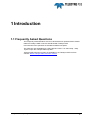
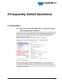
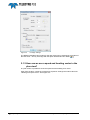
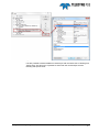
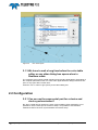
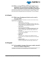
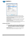
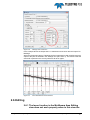
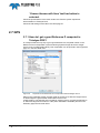
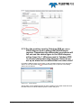
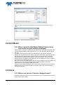
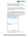
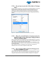
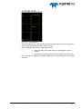
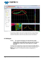
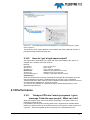
Frequently Asked Questions Teledyne PDS Version 1.0.4 July 2015 Teledyne RESON B.V. Stuttgartstraat 42- 44 3047 AS Rotterdam The Netherlands Tel.: +31 (0)10 245 15 00 www.teledyne-reson.com Amendment Record Sheet Rev. Date Reason for Modifications 1.0.4 07/07/2015 Item added: Replay 1.0.3 14/06/2015 Updated the manual with new items. 1.0.2 11/04/2015 Logging added. 1.0.1 01/10/2014 Modified text S-57 as it is now available in PDS2000. Introduction: Link to instruction movies added. 1.0.0 18/02/2013 First version of the FAQ Manual. Contents 1 Introduction 1.1 1 Frequently Asked Questions ........................................................................... 1 2 Frequently Asked Questions 3 2.1 Acquisition ....................................................................................................... 3 2.1.1 How can I see in the Plan View – Survey Coverage the surveyed area in colors? 3 2.1.2 How can we see a speed and heading vector in the plan view? ............... 4 2.1.3 We have to wait a long time before the color table editor or any other dialog box opens when in Realtime mode. ............................................................ 6 2.2 Configuration ................................................................................................... 6 2.2.1 Can we use the same serial port for a device and clock synchronization?6 2.2.2 When running RTK fixed GPS what height source should we use and should we disable heave from VRU in the reference point computation properties? ............................................................................................................. 7 2.3 Charts .............................................................................................................. 7 2.3.1 What type of background charts can be used in Teledyne PDS? ............. 7 2.4 Doppler ............................................................................................................ 7 2.4.1 Is it possible to increase the screen update rate with the use of Doppler integration? ............................................................................................................ 7 2.5 Echo Sounders ................................................................................................ 8 2.5.1 Is it possible to generate events in NCC (Navisound Control Center) that can be logged with the data, so that these annotations can be seen in the graphs? .................................................................................................................. 8 2.6 Editing .............................................................................................................. 9 2.6.1 The lasso function in the Multibeam Area Editing view does not work properly when in this view the ‘Connect beams with lines’ tool bar button is selected. ................................................................................................................. 9 2.7 GPS ............................................................................................................... 10 2.7.1 How do I get a good Reference Z computed in Teledyne PDS? ............. 10 2.7.2 For the position input to Teledyne PDS we use a GGA telegram from a differential GPS/Glonass receiver. Sometimes the differential corrections will fall out and the status figure in the GGA telegram will go from 2 to 1. What we need in Teledyne PDS is a sound alarm when this happens. How can we set up an alarm for lost differential correction data? ............................................................ 11 2.8 Grid Model ..................................................................................................... 12 2.8.1 When I open the Grid Model Editor it takes a long time before the grid model is displayed. .............................................................................................. 12 2.9 Heave ............................................................................................................ 12 2.9.1 Where can you see if heave is delayed heave? ...................................... 12 2.9.2 Is there a driver for the Octans Smart Heave? ........................................ 13 2.9.3 How to setup Novatel SPAN roll/pitch/heave driver? .............................. 13 2.10 Logging .......................................................................................................... 14 Teledyne PDS - Frequently Asked Questions Contents i 2.10.1 Why do we have a huge log file size when logging for only 10 seconds multibeam data and using POS MV True Heave? .............................................. 14 2.10.2 Why when logging snippets does the PDS file become double the size as the S7k file and is there a way to reduce the size? ........................................ 15 2.11 MotionScan ................................................................................................... 15 2.11.1 We are not able to establish communication with the MotionScan, is a other program using the same port? ................................................................... 15 2.12 Multibeam ...................................................................................................... 17 2.12.1 Is there some sort of tool or method in Teledyne PDS to determine the mean bias of the beams? .................................................................................... 17 2.12.2 I apply 180 to the yaw angle of the multibeam. How can I apply the 180 degree to the snippets as well? ........................................................................... 17 2.12.3 How does Teledyne PDS handle the Tx-Rx offset as set in the 7kCenter for the records 7006 and 7027? .......................................................................... 18 2.12.4 Do we have to enter the Tx-Rx offset in Teledyne PDS? ...................... 19 2.12.5 When the roll stabilization is already used in the RESON SeaBat 7k then what does Teledyne PDS do with the multibeam data? ...................................... 19 2.12.6 Does Teledyne PDS support the D-telegram for the Simrad EM3000 format? 19 2.12.7 Is there a way to start a new log file automatically in the RESON SeaBat 7k software after a limited file size? .................................................................... 20 2.12.8 The travel time from the 7027 record of the RESON Seabat 7101 is that corrected for the radius of the Rx array? ............................................................. 20 2.12.9 In the Editing I see gaps in my multibeam data while multibeam data is logged. 20 2.13 Multibeam Calibration ................................................................................... 20 2.13.1 Why do we see differences in our pitch multibeam calibration values, while the error parabola indicates a ‘very strong solution’? ................................ 20 2.14 Output............................................................................................................ 22 2.14.1 To control the flying of a tow-fish the nadir depth of the mounted sonar can be used. Is there a possibility to output the nadir depth as a single record? 22 2.14.2 How do I get a high speed output? ........................................................ 23 2.15 Performance .................................................................................................. 23 2.15.1 Teledyne PDS don’t start up anymore. I get a message ‘Failed to open project’. What can I do? ....................................................................................... 23 2.15.2 When I do a survey with RESON SeaBat 7k and Applanix POSMV, I see that the system stops after a while. It seems that there is not enough memory available. What can I do? .................................................................................... 24 2.15.3 Is it possible to autostart Teledyne PDS in the Acquisition mode? ....... 24 2.15.4 We have brief computer freezes that result in data loss. Any ideas about what could be causing the freezes? .................................................................... 24 2.16 Replay ........................................................................................................... 24 2.16.1 How can we use the original layout as used during Realtime? ............. 24 2.17 Reports .......................................................................................................... 25 2.17.1 In our trip reports is the date and time is always the same (jan-1970). How can we solve this problem? ......................................................................... 25 2.18 Sound Velocity .............................................................................................. 25 2.18.1 Does the RESON SeaBat 7k only use the SVS to determine phase difference, or does it apply a straight SVP (based on that SVS value) to the sonar data? ………………………………………………………………………………..25 2.18.2 What should we do when installing a svp to the MBE head but do not apply any MBE offsets in PDS as this is already done in the positioning system. (E.g. Applanix POSMV), but we like to use the SV values valid for correct depth. ………………………………………………………………………………...26 ii Contents Teledyne PDS - Frequently Asked Questions 2.19 Tide ................................................................................................................ 26 2.19.1 How do I setup Teledyne PDS for tide? ................................................. 26 2.20 System ........................................................................................................... 27 2.20.1 How should we set the 3D settings of the NVIDIA video card? ............. 27 2.21 Time Stamp ................................................................................................... 27 2.21.1 I have a time stamp warning message that appears when the Real Time Acquisition is started. ........................................................................................... 27 Teledyne PDS - Frequently Asked Questions Contents iii Figures Figure 2-1 Figure 2-2 Figure 2-3 Figure 2-4 Figure 2-5 Figure 2-6 Figure 2-7 Figure 2-8 Figure 2-9 Figure 2-10 Figure 2-11 Figure 2-12 Figure 2-13 Figure 2-14 Figure 2-15 Figure 2-16 Figure 2-17 Figure 2-18 Figure 2-19 Figure 2-20 Figure 2-21 Figure 2-22 Figure 2-23 Figure 2-24 iv Figures Logging page .......................................................................................................................3 Coverage Settings ...............................................................................................................4 Outline ..................................................................................................................................5 Two vessel layers.................................................................................................................6 Properties of the Reference Point Computation with Kalman Filter settings .......................8 Settings view of the NCC .....................................................................................................9 NCC with data and event markers .......................................................................................9 Properties of the Reference Point Computation with the Height Source .......................... 10 Geometry page with the sea level offset set ..................................................................... 11 Alarms dialog .................................................................................................................... 11 Alarm condition on the GPS mode.................................................................................... 12 Alarms dialog with the GPS alarm .................................................................................... 12 Attitude Computation of the Novatel SPAN[heave] .......................................................... 13 Data Sources with Novatel SPAN[heave] as primary source ........................................... 14 Time line when logging stops............................................................................................ 14 Properties of the Snippets Computation with the Multibeam Source ............................... 18 Properties of the Multibeam Device Data with the Tx-Rx offset ....................................... 19 Part of an XML file with the file size of the 7k log file........................................................ 20 Error parabola ................................................................................................................... 21 Profiles do not match ........................................................................................................ 22 Output Messages window with Multibeam xyz computation attached to ‘Depth below transducer’ .............................................................................................................. 23 Replay Options.................................................................................................................. 25 Tide Station Info dialog in the Tide Station Editor ............................................................. 26 3D Settings ........................................................................................................................ 27 Teledyne PDS - Frequently Asked Questions 1 Introduction 1.1 Frequently Asked Questions The Frequently Asked Questions are from clients that have questions about matters related to Teledyne PDS or sensors interfaced with Teledyne PDS. In this document the questions are divided into different chapters. This manual is also available as a HTML Help file. Press F1 or select Help > Help Topics to open the Teledyne PDS help files. Teledyne PDS Instruction movies are available on the Teledyne PDS YouTube channel. Watch Teledyne PDS instruction movies. Teledyne PDS - Frequently Asked Questions Introduction 1 2 Frequently Asked Questions 2.1 Acquisition 2.1.1 How can I see in the Plan View – Survey Coverage the surveyed area in colors? In the real time mode the multibeam data has to be logged to a grid model. Before that can be done, select in the Logging page as file format ‘PDS2000 Grid Model’, select or create in the section below the grid model in which should be logged and add the multibeam data to the ‘Data for grid model logging’ section. All three steps are indicated in the picture below. Make sure that the file format ‘PDS2000 Grid Model’ is checked!! Figure 2-1 Logging page In the Acquisition, select in the Toolbar of the Plan View – Survey Coverage the Coverage Settings ( ) to open the coverage settings for the view. Check in the Coverage Settings the Grid Model to display the grid model in the view and select a color table for the Z values in the grid model. The hitcount and standard deviation will have their own color table. Teledyne PDS - Frequently Asked Questions Frequently Asked Questions 3 Figure 2-2 Coverage Settings The different available color modes for the grid model can be selected in the toolbar of the Plan View – Survey Coverage with the option Grid Model Color Mode ( ). 2.1.2 How can we see a speed and heading vector in the plan view? In a plan view it is possible to show the speed and the heading as a vector. Open from the layer control the vessel layer properties. Change the outline value into ‘Heading and speed vector’. See Figure 2-3. 4 Frequently Asked Questions Teledyne PDS - Frequently Asked Questions Figure 2-3 Outline It is also possible to add an additional vessel layer with the outline set to Heading and speed vector. On this way it is possible to show both the vessel shape and the Heading and speed vector. Teledyne PDS - Frequently Asked Questions Frequently Asked Questions 5 Figure 2-4 Two vessel layers. 2.1.3 We have to wait a long time before the color table editor or any other dialog box opens when in Realtime mode. The computer gives priority to data collection and recording applications. Depending of the computer performance this can cause other applications as dialog boxes does not open or only open after a certain time. Press the <ALT> button to give priority to the called dialog box. 2.2 Configuration 2.2.1 Can we use the same serial port for a device and clock synchronization? No, when a serial port is used for the clock synchronization (time message) it is not possible to use the same port in the device setup. It is possible to use the same network socket for the clock synchronization and device setup. 6 Frequently Asked Questions Teledyne PDS - Frequently Asked Questions 2.2.2 When running RTK fixed GPS what height source should we use and should we disable heave from VRU in the reference point computation properties? The height source should be set to GPS height (RTZ). It is not necessary to disable heave from VRU because it will not have much influence as GPS Z is leading. The heave will be used to interpolate between two GPS positions, so it can be enabled. 2.3 Charts 2.3.1 What type of background charts can be used in Teledyne PDS? In PDS2000 different background charts/files can be used, some of them are only supported with an extra dongle. C-Map charts Works only with a C-Map dongle. For more information, see ‘Installing and Using C-Map’ in the chapter Installation of the PDS2000 User Manual. This format is not supported in the 64bit Teledyne PDS version. Tresco charts Works only with a Tresco dongle. For more information, see ‘Installing and Using Tresco’ in the chapter Installation of the Teledyne PDS User Manual. This format is not supported in the 64bit Teledyne PDS version. S-57 charts Are directly used in PDS2000; the S-57 charts. Refer to the Teledyne PDS User Manual. GeoTIFF files BSB charts Are indirect used in Teledyne PDS; the BSB charts (with extension KAP) can converted to GeoTIFF files in the Explorer. DXF files Electronic Charts These are charts generated in the old PDS1000 format. This format is not supported in the 64bit Teledyne PDS version. 2.4 Doppler 2.4.1 Is it possible to increase the screen update rate with the use of Doppler integration? The Teledyne PDS Reference Point Computation supports a Doppler integration. This computation can be opened in the Equipment page or in the Raw Data view. Teledyne PDS - Frequently Asked Questions Frequently Asked Questions 7 Figure 2-5 Properties of the Reference Point Computation with Kalman Filter settings The Doppler update starts after the time is passed as set in Maximum Age Position [sec], which is set by default on 2 seconds. When the time is lowered the Reference Point Computation will be updated faster after the position update. This will also depend on the update of the Doppler. For the Doppler integration the Kalman Filter has to be switched on, select a value for Kalman Filter Setting. Also the standard deviation of the position has to be replaced. This can be done with Position Std Overwrite(0=off). Enter here a standard deviation in m/sec to give it a good weight in the Kalman filter. In the Plan View and extra Vessel Layer can be added to display the calculated Doppler track. This track can assist in getting the right values for the Doppler scale and heading which can be entered in the Reference Point Computation. 2.5 Echo Sounders 2.5.1 Is it possible to generate events in NCC (Navisound Control Center) that can be logged with the data, so that these annotations can be seen in the graphs? From Teledyne PDS it is possible to send an event marker to NCC that also will be logged in the NCC logfile. To make this possible an output port has to be switched on in the NCC component. Select in NCC the option Settings to open the settings view of the NCC. 8 Frequently Asked Questions Teledyne PDS - Frequently Asked Questions Figure 2-6 Settings view of the NCC In the example above the Output Port 1 is switched on and check also the Output TD Message. Add in the Equipment page of Teledyne PDS an Output device with a DESO 25 event output to the port as selected in the Settings view (here Com 3). The results is that the event info is printed on the screen just like it will be on paper. Figure 2-7 NCC with data and event markers 2.6 Editing 2.6.1 The lasso function in the Multibeam Area Editing view does not work properly when in this view the Teledyne PDS - Frequently Asked Questions Frequently Asked Questions 9 ‘Connect beams with lines’ tool bar button is selected. Check the specifications of the used viedeo card. See the system requirment documentation of Teledyne PDS. Check the 3D settings of the video card. See page 27. 2.7 GPS 2.7.1 How do I get a good Reference Z computed in Teledyne PDS? In Teledyne PDS the only way to get a good Reference Z computed is when in the Reference Point Computation of the Positioning System Geogs device the Height Source is set on GPS Height [RTZ]. This computation can be opened in the Equipment page or in the Raw Data view. Figure 2-8 Properties of the Reference Point Computation with the Height Source When in the coordinate system a geoid model is present, then with the Height Source on GPS Height the geoid model is also taken into account. If GPS Height is not valid the sea level will be used as level to compute the Reference Z. Select as Height Source None or Tide (when tidal data is available) and set in the Geometry page the sea level offset. 10 Frequently Asked Questions Teledyne PDS - Frequently Asked Questions Figure 2-9 Geometry page with the sea level offset set 2.7.2 For the position input to Teledyne PDS we use a GGA telegram from a differential GPS/Glonass receiver. Sometimes the differential corrections will fall out and the status figure in the GGA telegram will go from 2 to 1. What we need in Teledyne PDS is a sound alarm when this happens. How can we set up an alarm for lost differential correction data? In Teledyne PDS an alarm can be setup. In the Acquisition with the menu item Edit > Alarms or from the toolbar with the Alarms dialog can be opened. In this dialog alarms can be defined. Figure 2-10 Alarms dialog Add an alarm for the GPS and make an alarm condition on the GPS mode that when the GPS mode is not RTK FIXED anymore an alarm will go off. Teledyne PDS - Frequently Asked Questions Frequently Asked Questions 11 Figure 2-11 Alarm condition on the GPS mode When you want a sound alarm for the GPS mode alarm, check the option Sound Alarm. Figure 2-12 Alarms dialog with the GPS alarm 2.8 Grid Model 2.8.1 When I open the Grid Model Editor it takes a long time before the grid model is displayed. When it takes a long time it means that a lot of data has to be loaded in the editor, this can be background data (C-Map, DXF files, etc.) or a very big grid model with small cell size. The reason that background charts are loaded when a grid model is opened is because the context menu option Save as defaults is used before. With this option all the layers that are opened will be saved, so when a new grid model is opened all layers with their files that are saved will be opened in the editor. This is nice for the user because he don’t have to select the layers for the background, runline, polygons, etc. each time he opens a grid model. When a lot of layers are added and saved with Save as default it becomes slower. The only way is to remove all the obsolete layers or remove/rename the filename ‘EditorView.upd’ in the Teledyne PDS project folder. If the file is removed/renamed then when a grid model is opened the layers have to be added one by one to get all information in the editor again. Use Save as default to save the layout again. 2.9 Heave 2.9.1 Where can you see if heave is delayed heave? In the Device Data of the heave in the Raw Data view it is only visible with the value (in msec) of the Dynamic Delay. 12 Frequently Asked Questions Teledyne PDS - Frequently Asked Questions The time of the heave data is the same time as for the other sensors. This time is already corrected for the delay. So there is no problem the interpolate the delayed heave with other sensor data, because is in the same range. With a delayed heave a closed logfile will still log data for the time of the delay. This is necessary to process the data in that logfile with the right heave. 2.9.2 Is there a driver for the Octans Smart Heave? This should be a delayed heave driver. The sensor has two different possible output formats, one of them is the PosMV GRP111. This format is identical with the PosMV Ethernet 111 in Teledyne PDS. 2.9.3 How to setup Novatel SPAN roll/pitch/heave driver? In Teledyne PDS there will be two drivers needed, one for the roll and pitch and one for the heave, because the roll/pitch and heave are outputted on two different ports. Because Teledyne PDS needs roll, pitch and heave from one source, a dependency has to be selected in the heave driver. First select the vru driver and then the heave driver. Select in the attitude computation for the Roll/Pitch Data Source the Device Data of the Novatel SPAN[vru]. Figure 2-13 Attitude Computation of the Novatel SPAN[heave] To get everything working make sure that the Novatel SPAN[heave] driver is the primary data source for the Roll+Pitch+Heave. Teledyne PDS - Frequently Asked Questions Frequently Asked Questions 13 Figure 2-14 Data Sources with Novatel SPAN[heave] as primary source 2.10 Logging 2.10.1 Why do we have a huge log file size when logging for only 10 seconds multibeam data and using POS MV True Heave? This is caused due to the use of the POS MV True heave. When Teledyne PDS logging is stopped the system continues to log until all the data for that time is collected. True heave has a delay of 2 minutes (to be exact: 134.9seconds). This means all data is still logged until two minutes after the logging was stopped. This explains a file of 10 seconds still has a huge size. Example: Positioning update 1 Hz (every 1 sec) Heading update 20 Hz (every 0.05 sec) Multibeam update 15 Hz (every 0.083sec) R/P update 50 Hz (every 0.002 sec) See Figure 2-15 in this example the positioning is the latest point, so all data is logged until this point (dark colors) Figure 2-15 Time line when logging stops True heave is only used during post processing. It is a more accurate heave than Realtime heave. It might be used when RTK is not available and you notice problems with your heave. Turn it off or remove it from the vessel configuration when not needed. The Teledyne PDS device driver ‘POS MV Ethernet 111’ is used to apply True Heave. From of Teledyne PDS version 3.8.0.0: 14 Frequently Asked Questions Teledyne PDS - Frequently Asked Questions A warning opens when Realtime is closed while delayed heave data is logged. Only the Trueheave device data is logged. 2.10.2 Why when logging snippets does the PDS file become double the size as the S7k file and is there a way to reduce the size? It is possible that a PDS logfile is twice the size of the S7k file because the PDS file contains the processed result of all the observations. When you like to have less data: select another beam pattern (Equi-angle instead of Equi-distant) and reduce the ping rate. The final result will be the same, only the oversampling will be less. . 2.11 MotionScan 2.11.1 We are not able to establish communication with the MotionScan, is a other program using the same port? The MotionScan device use socket 7000 for the communication with PDS. A conflict occurs when another program is also using socket port 7000. Use the command netstat –b to get an overview with used socket ports. 1. Search for the command prompt (CMD.exe). 2. Run the command prompt as administrator. Teledyne PDS - Frequently Asked Questions Frequently Asked Questions 15 3. Enter the command: netstat –b 4. Check the overview if another program use socket 7000. 16 Frequently Asked Questions Teledyne PDS - Frequently Asked Questions 5. Close the program using socket 7000. 2.12 Multibeam 2.12.1 Is there some sort of tool or method in Teledyne PDS to determine the mean bias of the beams? With the Export in the Grid Model or CUBE tab of the Multibeam Area Editing view a mean bias per beam relative to the Z average is exported. For each beam per ping the difference is calculated with the Z average of the grid model cell. When this is done for all the pings a mean difference per beam is computed. This mean difference per beam is exported in the column SP1 (single ping) of the CSV file. When multiping is available the columns MP1-4 will be filled. 2.12.2 I apply 180 to the yaw angle of the multibeam. How can I apply the 180 degree to the snippets as well? The snippets is using the mounting angles set in the multibeam device data. This is done in the Snippets Computation by selecting the Multibeam Source. When one multibeam is selected in the Equipment list it will automatically be selected in the Snippets Computation. Teledyne PDS - Frequently Asked Questions Frequently Asked Questions 17 Figure 2-16 Properties of the Snippets Computation with the Multibeam Source 2.12.3 How does Teledyne PDS handle the Tx-Rx offset as set in the 7kCenter for the records 7006 and 7027? In Teledyne PDS the Multibeam XYZ Computation makes the following decision how to handle the Tx-Rx offset: No correction applied when Tx-Rx offset is zero and Teledyne PDS receives record 7006 with XYZ compensation On. No correction applied when Tx-Rx offset is non-zero and Teledyne PDS receives record 7006 with XYZ compensation On. No correction applied when Tx-Rx offset is zero and Teledyne PDS receives record 7006 with XYZ compensation Off. Correction applied when Tx-Rx offset is non-zero and Teledyne PDS receives record 7006 with XYZ compensation Off. No correction applied when Tx-Rx offset is zero and Teledyne PDS receives record 7027. Correction applied when Tx-Rx offset is non-zero and Teledyne PDS receives record 7027. The RESON SeaBat 7111 outputs already corrected data and reports a zero or no TxRx offset. 18 Frequently Asked Questions Teledyne PDS - Frequently Asked Questions 2.12.4 Do we have to enter the Tx-Rx offset in Teledyne PDS? Normally Teledyne PDS gets the Tx-Rx offset from the RESON SeaBat 7k and will use this (per frequency another offset). Suppose the offset is entered wrong in the 7k software then Teledyne PDS allows the user to overwrite the offset in the post processing by means of changing the attributes in the Properties of the Multibeam Device Data. So it is better not to enter the Tx-Rx offset in Teledyne PDS unless it is needed. Figure 2-17 Properties of the Multibeam Device Data with the Tx-Rx offset 2.12.5 When the roll stabilization is already used in the RESON SeaBat 7k then what does Teledyne PDS do with the multibeam data? When in Teledyne PDS for the multibeam the driver RESON SeaBat 7k is used the for the multibeam, data record 7027 will be used. When the driver RESON SeaBat 7k Old 7006 is used, record 7006 will be used in Teledyne PDS. When Teledyne PDS uses record 7027 it will not check if the roll stabilization is used. Teledyne PDS will use the available raw beam angle data in the record and will apply all corrections needed. When Teledyne PDS uses a combination of the records 7004 / 7006 with roll stabilization then no roll correction is applied in Teledyne PDS. 2.12.6 Does Teledyne PDS support the D-telegram for the Simrad EM3000 format? Teledyne PDS does support the D datagram (44h in Simrad specifications). However there is a limit of the number of beams the datagram can handle (254). With a sonar configuration that produces more than 254 beams the datagram is not supported. Teledyne PDS - Frequently Asked Questions Frequently Asked Questions 19 There are newer datagrams which support more beams (for newer sonars). However these have not been implemented in Teledyne PDS at the moment of writing. 2.12.7 Is there a way to start a new log file automatically in the RESON SeaBat 7k software after a limited file size? In the XML files in the \bin folder in the installation folder of the RESON SeaBat 7k software you can set the maximum file size for 7k files which are recorded in the 7kCenter. By default it is set to 1 GB. Figure 2-18 Part of an XML file with the file size of the 7k log file 2.12.8 The travel time from the 7027 record of the RESON Seabat 7101 is that corrected for the radius of the Rx array? The two way travel time in the 7027 record is from Tx reference point via the reflector to the Rx reference point. This is not the way the real time is travelling through the water but it is a practical value to calculate and it is a measurement between definable points. In reality the raw travel time to the cylinder cannot be determined because it is different for each Rx element and it will have after beam forming a specific offset. After this a correction is done which can be to each point but a choice is made to do this to a central point, the Rx reference point. 2.12.9 In the Editing I see gaps in my multibeam data while multibeam data is logged. The gaps can be caused by the fact that in the log data file(s) for that location no valid position; heading or vru data is available. Another reason can be that the log data file(s) are corrupt. In most cases this can be repair with a tool in the Editing. Select the menu option Tools > Repair File(s) and select a repair for the current file or for all the files in the file set. A repair can take a long time especially when the files are big. 2.13 Multibeam Calibration 2.13.1 Why do we see differences in our pitch multibeam calibration values, while the error parabola indicates a ‘very strong solution’? In this case the automatic calibration method is used for the multibeam calibration. After the calibration, the error parabola indicates a very strong solution 20 Frequently Asked Questions Teledyne PDS - Frequently Asked Questions Figure 2-19 Error parabola It was concluded by the customer when the error parabola gives a very strong solution the automatic calculated calibration value is correct. This is a WRONG conclusion. It only applies when: 1. Data as used in the profiles does not contain spikes. (jump in height) 2. The data of the profiles have the same height for the same point. In this case when analyzing the profiles, a difference in height between the two profiles was seen. Teledyne PDS - Frequently Asked Questions Frequently Asked Questions 21 Figure 2-20 Profiles do not match This means the calibration values must be changed manually in a value resulting in matching profiles (falling on each other). This value is the correct calibration value. Conclusion: always take a critical look to the profiles as used for the calibration. 2.14 Output 2.14.1 To control the flying of a tow-fish the nadir depth of the mounted sonar can be used. Is there a possibility to output the nadir depth as a single record? In Teledyne PDS the nadir depth is computed. With the output driver NMEA-DBT the nadir depth can be outputted. After the output driver is added to the Equipment list use to open the Output Message window to attach the right computation to the depth below transducer. For a multibeam this should be the Multibeam xyz computation. 22 Frequently Asked Questions Teledyne PDS - Frequently Asked Questions Figure 2-21 Output Messages window with Multibeam xyz computation attached to ‘Depth below transducer’ The frequency of the output depends on the update rate of the multibeam system. In principal the output follows the ping rate. 2.14.2 How do I get a high speed output? The output rate is depending on the input rate of the data related to the output. An example of the settings of an input driver is: [General] SyncMode=0 SyncCount=1 SyncString=10 DataRate=20 TimeOut=5.0 NumberOfMessages=1 AlwaysNotify=1 //Sync on terminator //Sync length //Sync character is linefeed //Maximum expected data rate is 20 Hz //Maximum time out is 5 seconds //Number of messages defined in this file When only de data rate is set high Teledyne PDS accepts all the message up to this rate but internally the system is notified 5 times per second. For the calculation Teledyne PDS uses all the values but since Teledyne PDS notifies 5 times per second the output will be updated max. 5 time per second. To overcome this problem for a high speed output set/add AlwaysNotify=1 to the dependent input driver(s). 2.15 Performance 2.15.1 Teledyne PDS don’t start up anymore. I get a message ‘Failed to open project’. What can I do? When this happens most of the times the file ‘project.prj’ is corrupted. There is no possibility to repair this file. It is possible to get the project running again when a log data file is available that is made in the project. Select in the Control Center the menu option Create Project from Log Data..., select the log data file and a new project is created based on the Teledyne PDS - Frequently Asked Questions Frequently Asked Questions 23 information in the log data file. Copy the file ‘project.prj’ from the new project to the broken project. The file can be found in the project folder. Now the broken project can be opened again. 2.15.2 When I do a survey with RESON SeaBat 7k and Applanix POSMV, I see that the system stops after a while. It seems that there is not enough memory available. What can I do? See the system specifications in the Teledyne PDS User Manual on how much memory is needed for this kind of surveys. Another issue can be that a delayed heave driver is used with a delay buffer that is too big for the system. Some delayed heave drivers have a delay of 180 seconds. When there is not enough memory available to keep these 180 seconds of data in memory the system crashes. 2.15.3 Is it possible to autostart Teledyne PDS in the Acquisition mode? When you add “-A” behind the Master.exe (Control Center shortcut target) we will automatically enter the Realtime Acquisition. When a clock synchronization is used, PDS2000 will wait until the clock sync is established. 2.15.4 We have brief computer freezes that result in data loss. Any ideas about what could be causing the freezes? Not often they are structural or persistent, and normally how the issue is created can be deduced by the Teledyne PDS support. One thing that the user can try to solve the problem is changing the way the computations are running in Teledyne PDS. Select in the Acquisition the menu option Edit > Use Single Thread For All Comps. This will force Teledyne PDS to run all computations in one single thread instead of each sensor computation in its own thread. 2.16 Replay 2.16.1 How can we use the original layout as used during Realtime? Uncheck the checkboxes External layout and Keep same layout when playing log files of the Replay>Options menu. 24 Frequently Asked Questions Teledyne PDS - Frequently Asked Questions Figure 2-22 Replay Options 2.17 Reports 2.17.1 In our trip reports is the date and time is always the same (jan-1970). How can we solve this problem? The reason that the report has a problem with the date and time is that probably in the vessel name a – (minus) sign is used. The data and time for the report is extracted from the log data filename which contains vessel name, trip number and date/time. Teledyne PDS is looking for the first minus sign in the name which is normally just before the data and time. If in the vessel name already a minus sign is used can the date and time not be found directly after the minus sign and is filled with the default date/time. Solve this problem by not using minus signs in the vessel name. 2.18 Sound Velocity 2.18.1 Does the RESON SeaBat 7k only use the SVS to determine phase difference, or does it apply a straight SVP (based on that SVS value) to the sonar data? In the RESON SeaBat 7k for the beam forming only the SVS is used. In Teledyne PDS a retracing is done using the SVP and this is only possible after mounting and attitude correction. Teledyne PDS - Frequently Asked Questions Frequently Asked Questions 25 2.18.2 What should we do when installing a svp to the MBE head but do not apply any MBE offsets in PDS as this is already done in the positioning system. (E.g. Applanix POSMV), but we like to use the SV values valid for correct depth. When you make the multi-beam the vessel reference point and you enter the proper sea level the svp sensor will handled properly. 2.19 Tide 2.19.1 How do I setup Teledyne PDS for tide? The setup for tide starts in the Equipment page of the vessel configuration. Add a tide gauge for the real time received tide and add a second tide gauge for the manual tide. The manual tide can be useful when occasionally no data from the real time tide gauge is received. For both devices automatically a tide computation is added. In the Advanced Computations it is not needed to add a tide computation. Select here only a tide computation when a different tide computation setup from the one made in the Equipment has to be defined. Don’t add a manual tide computation this one is already created in the Equipment A tide station has to be created for the in the real time received tide. There is no need to have one for the manual tide. When the tide station is created, open the tide station info by selecting in the Tide Station Editor. Figure 2-23 Tide Station Info dialog in the Tide Station Editor In the Tide Station Info dialog the location and ID of the tide gauge can be defined. Also the maximum gap and maximum extend can be set. Both are in seconds. A tide value must be received within the set maximum gap time. When the maximum time gap is too short it is possible that no tidal data is received and the tide computation 26 Frequently Asked Questions Teledyne PDS - Frequently Asked Questions gives an error. When the maximum extend time is too short Teledyne PDS will not interpolate between the received tide values. This is visible in the Tide Station Editor as single crosses and not as crosses connected with a line. In the Acquisition add to the screen layout via the menu options Tools > Equipment Control the display for the manual input. If in the manual input view the option Force Manual Tide is checked the manual tide becomes the primary tide source. When it is unchecked the tide source that is set as primary in the Data Source will be the primary data source. 2.20 System 2.20.1 How should we set the 3D settings of the NVIDIA video card? Set the 3D settings of the video card to NVIDIA instead of autoselect or Intel. Figure 2-24 3D Settings 2.21 Time Stamp 2.21.1 I have a time stamp warning message that appears when the Real Time Acquisition is started. The warning ‘time stamping in the future’ may occur for a few seconds during startup, after that it should not occur anymore. Time stamp in the future means that Teledyne PDS receives a message from a device where the time in the message is newer than the computer time. In other words Teledyne PDS receives the result of a measurement in the future. This problem can occur when there is a clock synchronization error or when the PosMV is predicting too hard. Teledyne PDS - Frequently Asked Questions Frequently Asked Questions 27 Grid Model Color Mode - 4 ─H─ Index Heave - 13 ─I─ Input Rate - 23 ─K─ Kalman Filter - 8 KAP - 7 ─A─ Acquisition - 24, 27 Advanced Computations - 26 Alarm - 11 ─B─ Background Chart - 7 BSB - 7 ─C─ Clock Synchronization - 24, 27 C-Map - 7 Coverage Settings - 3 CSV File - 17 CUBE - 17 ─D─ Data Source - 13 Delayed Heave - 24 Device Data - 13 Doppler - 7 DXF File - 7 ─E─ Electronic Chart - 7 Equipment Page - 7, 9, 10, 26 Export - 17 ─L─ Logging Page - 3 ─M─ Manual Tide - 26 Multibeam Area Editing View - 17 Multibeam Device Data - 19 Multibeam Source - 17 Multibeam XYZ Computation - 18, 22 ─N─ Nadir Depth - 22 NCC - 8 ─O─ Output Device - 9 Output Rate - 23 ─P─ PDS2000 Grid Model - 3 Pitch - 13 Plan View – Survey Coverage - 3 ─R─ File Repair - 20 Frequently Asked Questions - 1 Raw Data View - 7, 10, 13 Reference Point Computation - 7, 10 RESON SeaBat 7k - 19, 20, 25 RESON SeaBat 7k Old 7006 - 19 Roll - 13 Roll Stabilization - 19 ─G─ ─S─ Geoid Model - 10 GeoTIFF File - 7 GPS - 10, 11 GPS Mode - 11 Grid Model - 3, 12, 17 S-57 - 7 Sea Level - 10 Simrad EM3000 Format - 20 Snippets Computation - 17 ─F─ Teledyne PDS - Frequently Asked Questions Index 29 ─T─ Tide - 26 Tide Station Editor - 26 Time stamp - 27 Tresco - 7 Two Way Travel Time - 20 Tx-Rx Offset - 18, 19 ─V─ Vessel Layer - 8 ─X─ XML File - 20 30 Index Teledyne PDS - Frequently Asked Questions