1
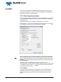
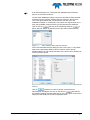
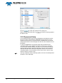
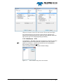
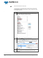
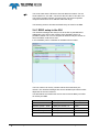
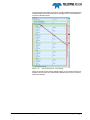
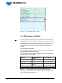
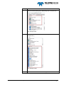
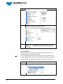
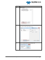
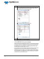
PDS2000 Configuration Manual Odom Multibeam Version 1.0.4 January 2015 Teledyne RESON B.V. Stuttgartstraat 42- 44 3047 AS Rotterdam The Netherlands Tel.: +31 (0)10 245 15 00 www.teledyne-reson.com Amendment Record Sheet Rev. Date Reason for Modifications 1.0.4 15/01/2015 Text modified. (Added IP address MB2 RTA) 1.0.3 05/12/2014 PDS2000 configuration MB2 text timing modified. 1.0.2 30/10/2014 PDS2000 configuration: Added section ‘MB2” PDS2000 configuration: Modified flow diagram in section Introduction Introduction: Link added PDS2000 instruction movies 1.0.1 07/04/2014 Manual updated to PDS2000 version 3.8.2.5 1.0.0 06/03/2014 First version of the Odom Multibeam manual Contents 1 Introduction 1 1.1 Introduction ............................................................................................................. 1 2 PDS2000 Configuration 3 2.1 Introduction ............................................................................................................. 3 2.2 ES3 ......................................................................................................................... 4 2.2.1 Clock Synchronization .................................................................................. 4 2.2.1.1 Input ..................................................................................................... 4 2.2.2 Equipment Setup .......................................................................................... 6 2.2.2.1 Multibeam – ES3 ................................................................................. 7 2.2.2.2 VRU ..................................................................................................... 8 2.2.2.3 Positioning System .............................................................................. 9 2.2.2.4 Compass ............................................................................................. 9 2.2.2.5 Doppler .............................................................................................. 10 2.2.2.6 Sound Velocity................................................................................... 10 2.3 MB1 ...................................................................................................................... 10 2.3.1 Clock synchronization ................................................................................. 11 2.3.2 Equipment Setup ........................................................................................ 12 2.3.2.1 Multibeam – MB1............................................................................... 12 2.3.2.2 VRU ................................................................................................... 15 2.3.2.3 GPS ................................................................................................... 16 2.3.2.4 Compass ........................................................................................... 18 2.3.2.5 Sound velocity ................................................................................... 19 2.4 MB2 ...................................................................................................................... 21 2.4.1 RRIO setup in the SUI ................................................................................ 22 2.4.2 RRIO setup in PDS2000 ............................................................................. 24 2.4.2.1 Device selection ................................................................................ 24 2.4.2.2 IO port ................................................................................................ 26 2.4.2.3 Timing ................................................................................................ 30 2.4.2.4 PDS2000 Clock synchronization ....................................................... 32 Odom Multibeam - PDS2000 Configuration Manual Contents i Figures Figure 2-1 Figure 2-2 Figure 2-3 Figure 2-4 Figure 2-5 Figure 2-6 Figure 2-7 Figure 2-8 Figure 2-9 Figure 2-10 Figure 2-11 Figure 2-12 Figure 2-13 Figure 2-14 Figure 2-15 Figure 2-16 Figure 2-17 Figure 2-18 Flow diagram........................................................................................................................3 Clock Synchronization .........................................................................................................4 Select Interface dialog with RTA selected ...........................................................................5 Interfacing dialog with the new port for the ZDA message from the RTA box .....................5 Interfacing dialog with the serial port for the 1 PPS pulse ...................................................6 Timestamp Mode is Time in Message for the Positioning System (left) and is Computer Clock for the other devices, here the Odom ES3 (right) .....................................7 Select Interface dialog with Socket selected .......................................................................7 Interfacing with Socket port for the ES3 ..............................................................................8 Part of the ES3.ini file with the RemotePort_Output1 ..........................................................8 Interfacing with RTA port for the VRU .................................................................................8 Interfacing with RTA port for the positioning system ...........................................................9 Interfacing with RTA port for the compass ...........................................................................9 Interfacing with RTA port for the doppler .......................................................................... 10 Interfacing with RTA port for the sound velocity ............................................................... 10 Overview MB2 Sonar system ............................................................................................ 21 SUI Hardware pane - RRIO .............................................................................................. 22 SUI Hardware pane – Port Settings .................................................................................. 23 SUI Hardware pane - Sensors .......................................................................................... 24 ii Figures Odom Multibeam - PDS2000 Configuration Manual 1 Introduction 1.1 Introduction This document is made as an additional section for the Odom ES3, the Odom MB1 and the Odom MB2 Multibeam User Manuals. This manual explains the interface setup of PDS2000 for these Odom Multibeams. The Odom sonar and the other sensors (navigation, motion, heading and sound velocity) are interfaced to the RTA (Real Time Appliance) box. The RTA box timestamps this data. Therefore in PDS2000 the setup of the clock synchronization and the interface to the different sensors is different from the standard interfacing in PDS2000. This manual is also available as a HTML Help file. Press F1 or select Help > Help Topics to open the PDS2000 help files. PDS2000 instruction movies are available at the PDS2000 YouTube channel. Watch PDS2000 instruction movies. Odom Multibeam - PDS2000 Configuration Manual Introduction 1 2 PDS2000 Configuration 2.1 Introduction Below an example of a flow diagram with the setup between Sensors, PDS2000 and a RTA box. For this example an Odom MB1 is illustrated. The Odom ES3 and MB2 flow diagram is similar except there is an external time stamp signal (PPS and ZDA) required. The GPS and heading sensor could optional be installed in the RTA. The motion sensor could be optionally installed in the sonar. Refer to the Odom user manuals for details. GPS (If GPS not installed in RTA) Data collection computer Heading (PDS2000) (If heading GPS not installed in RTA) MB1 Controller Computer RTA SV Probe MB1 Sonar Figure 2-1 Motion Sensor (If motion sensor not installed in sonar) Key: RS232 Serial Cable Ethernet Cable Wet Mateable cable Flow diagram Odom Multibeam - PDS2000 Configuration Manual PDS2000 Configuration 3 2.2 ES3 This section summarizes the PDS2000 interfacing with the Odom ES3. Clock synchronization is used under certain conditions and in PDS2000 the RTA I/O interface must be defined. 2.2.1 Clock Synchronization To avoid time related errors and alarms, and when sensors are connected to the PDS2000 computer it selves, clock synchronization is needed as described below. For accurate clock synchronization a PPS signal must be used. Select System > Clock Synchronization from the menu bar or click on in the toolbar to open the Clock Synchronization window. Figure 2-2 Clock Synchronization When everything is setup as discussed below, check the option Enable Clock Synchronization and close the Clock Synchronization window with . With this option the clock synchronization will be activated and Realtime will only be available when the ClockSync module receives the input message(s). Select the option Use PDS2000 ClockSync module for clock synchronization’ and select as clock device driver the driver ‘Generic ZDA + 1PPS[tim]’ in the list. Click on next the list to select the drivers as the selected clock device. 2.2.1.1 Input In the input the port(s) for the time and pulse have to be selected. It is possible to have one or two ports selected; one port for both the time message and the pulse or one for the time message and one for the pulse. 4 PDS2000 Configuration Odom Multibeam - PDS2000 Configuration Manual If the time message is on a serial port then PDS2000 expect that the pulse is on the same serial port. For the Odom Multibeam setup the clock synchronization takes the ZDA message from the network message which is send from the RTA box. The 1 PPS pulse will be split, one to the RTA box and one to the PDS2000 computer on a serial port. Using these two signals, ZDA and 1 PPS, the PDS2000 computer will be synchronized with the GPS time. Click on the top and click in the Interfacing dialog on to add a new port. Select as interface RTA in the Select Interface dialog. Figure 2-3 Select Interface dialog with RTA selected Give in the New Network Port dialog the port a new name, f.i. RTA-GPS. Select in the Interfacing dialog as Sensor type the option GPS as displayed below. Do not change the Base Port number; this is already set on the right port number. Figure 2-4 RTA box Interfacing dialog with the new port for the ZDA message from the Click on to add the new port to the list of interface ports. After the time message is set, click on the second and select in the Interfacing dialog the right COM port for the 1 PPS pulse. Check if the settings for the serial port are set as displayed below. Odom Multibeam - PDS2000 Configuration Manual PDS2000 Configuration 5 Figure 2-5 Click on Interfacing dialog with the serial port for the 1 PPS pulse to confirm the settings for the serial port. When both ports are setup click on the Device Test. to test the incoming signals in 2.2.2 Equipment Setup In the Equipment page of the vessel configuration the different sensors have to be setup. All data feed to PDS2000 from the RTA box is time stamped in the RTA box. For these sensors, PDS2000 will use the time stamp implemented in the messages from the RTA box instead of its own timestamp. In order for PDS2000 to use the time stamp from the RTA box the ‘Timestamp Mode’ for the different sensors must be set on Computer Clock (this is the default setting). As noted, do not confuse this with the common PDS computer clock time stamping, with the RTA as interface selected PDS will use the RTA time tag. When sensors do not have a ‘Timestamp Mode’ in the Properties of their device driver, then the time stamp is always Computer Clock. 6 PDS2000 Configuration The only exception is the Positioning System; here the ‘Timestamp Mode’ should be Time in Message. Odom Multibeam - PDS2000 Configuration Manual Figure 2-6 Timestamp Mode is Time in Message for the Positioning System (left) and is Computer Clock for the other devices, here the Odom ES3 (right) As mentioned above for the sensors received from the RTA box the interface port should always be RTA. Select for each different sensor the right sensor type in the Interfacing dialog (see below). 2.2.2.1 Multibeam – ES3 The Multibeam – ES3 data will go from the RTA box to the ES3 Controller computer and from the ES3 Controller computer back to the network switch in the RTA box. Therefor the interface port for the Multibeam – ES3 should be Socket and not RTA. Select as interface Socket in the Select Interface dialog. Figure 2-7 Select Interface dialog with Socket selected Odom Multibeam - PDS2000 Configuration Manual PDS2000 Configuration 7 Figure 2-8 Interfacing with Socket port for the ES3 The local port is 4040. To be sure what the local port is, please check in the ES3.ini file what the host port setting should be. Look for the item ‘RemotePort_Output1’. Figure 2-9 Part of the ES3.ini file with the RemotePort_Output1 2.2.2.2 VRU Select as sensor type ‘MRU’ for the VRU sensor. Figure 2-10 8 PDS2000 Configuration Interfacing with RTA port for the VRU Odom Multibeam - PDS2000 Configuration Manual 2.2.2.3 Positioning System Select as sensor type ‘GPS’ for the Positioning System. Figure 2-11 Interfacing with RTA port for the positioning system 2.2.2.4 Compass Select as sensor type ‘Heading’ for the Compass sensor. Figure 2-12 Interfacing with RTA port for the compass Odom Multibeam - PDS2000 Configuration Manual PDS2000 Configuration 9 2.2.2.5 Doppler Select as sensor type ‘ADCP’ for the Doppler sensor. Figure 2-13 Interfacing with RTA port for the doppler 2.2.2.6 Sound Velocity Select as sensor type ‘Sound Velocity’ for the Sound Velocity sensor. Figure 2-14 Interfacing with RTA port for the sound velocity 2.3 MB1 This section summarizes the PDS2000 interfacing with the Odom MB1. 10 PDS2000 Configuration The MB1 use the Odom ‘Image’ software to control the MB1 and sends data to PDS2000. The minimum requirements for the MB1 controller computer are an Intel i7 quad core or better processor, minimum of 8 GB RAM and windows 7 as operate system. Refer to the Odom manual for details. Odom Multibeam - PDS2000 Configuration Manual 2.3.1 Clock synchronization When all the signals are received into PDS2000 by means of the Ethernet UDP connection from the MB1, than there is no PDS clock synchronization needed. The RTA time stamped its internal or external connected devices. (E.g. GPS, heading etc.) When additional devices are connected to the PDS2000 computer, clock synchronization is needed. This is the same method as for the ES3. Refer to section ‘Clock synchronization’ of the ES3 on page 4 When ‘time in the future’ alerts occur in PDS2000 it is better to clock synchronize PDS2000 although this alert does not affect the data quality. The clock synchronization does not need to be very accurate for this purpose. For example a GPS only timestamp could be used. This message is supplied by the RTA-Image software. (The ‘Time in the future’ alarms should not occur in PDS2000 version 3.8.2.5 or higher as this was fixed.) The table below summarizes the procedure. Step Action 1 Click in the PDS2000 Control Center at the clock synchronization icon. Odom Multibeam - PDS2000 Configuration Manual PDS2000 Configuration 11 Step Action 2 1: Tick the ‘Enabled clock synchronization’ checkbox 2: Tick the ‘Use PDS2000 clocksync module for clock synchronization’ radio button. 3: click ‘Select’ and select the RTA interface. Select the RTA interface as also used for the GPS. See section ‘GPS’ on page 16 4: Click ‘OK’ 2.3.2 Equipment Setup As also for the ES3 the connected sensors as a GPS, heading sensor etc. have to setup. With the MB1 a RTA box is used. This RTA box could optionally contain sensors as for example a GPS receiver. Refer to the MB1 user manual for more details. 2.3.2.1 Multibeam – MB1 The MB1 outputs TDY messages for the multibeam data. The messages are time stamped in the Odom RTA box and passed through PDS2000 by the ODOM Image software. In PDS2000 as interface type ‘RTA’ must be used, and as time stamp method ‘Time in message’. The table below summarizes the procedure to setup the MB1 in PDS2000. 12 PDS2000 Configuration Odom Multibeam - PDS2000 Configuration Manual Step 1 Action Select the ‘Odom TDY’ Device Driver in the Multibeam Group of the configuration’s equipment page. Click ‘ Add’ to add it to the device list. 2 Click ‘I/O port’ the ‘RTA’ interface. 3 Click ’RTA’ and press ‘OK’. 4 Give a name and press ‘OK’ Odom Multibeam - PDS2000 Configuration Manual followed by ‘Add’ to add PDS2000 Configuration 13 5 Select the correct Port number. By default this is 56002 but could be changed in the Odom Image software Network settings. Refer to the MB1 manual. Tick the ‘TDY data from Image’ checkbox. Click ‘OK’. 6 14 PDS2000 Configuration Double click in the device list at ‘Multibeam Odom TDY’. Odom Multibeam - PDS2000 Configuration Manual 7 Click at the ‘Timestamp Mode’ field and select in the drop-down list ‘Time in message’. 8 Note in this property display you could also select the correct offset for the Multibeam. 2.3.2.2 VRU As the VRU data is time stamped in the RTA box and implemented in the TDY message, use the same RTA interface setup as for the MB1. Notice for the ES3 this is not the case. The table below summarizes the steps to select the VRU with the RTA interface. When the RTA interface must be created refer to step 2 in the MB1 setup above. Odom Multibeam - PDS2000 Configuration Manual PDS2000 Configuration 15 Step 1 Action Select the TSS1 device driver in the VRU group of the vessel configuration’s equipment page. Click ‘Add’ 2 to add it to the device list. Click ‘I/O port’ and select the created RTA port. (in this example Image’) with message type ‘TDY data from Image’. It is important to select for all RTA interfaces the same.(In our example ‘Image’) Click ‘OK’ 3 There is no timestamp mode selection for a VRU. PDS2000 uses automatically the time in the TDY message. 2.3.2.3 GPS As the GPS data is time stamped in the RTA box and implemented in the TDY message, use the same RTA interface setup as for the MB1. Notice for the ES3 this is not the case. The table below summarizes the steps to select the GPS with the RTA interface. When the RTA interface must be created refer to step 2 in the MB1 setup above. 16 PDS2000 Configuration Odom Multibeam - PDS2000 Configuration Manual Step 1 Action Select the NMEA 2.3 GGA device driver in the Positioning system Geogs group of the vessel configuration’s equipment page. Click ‘Add’ 2 to add it to the device list. Click ‘I/O port’ and select the created RTA port. (in this example Image’) with message type ‘TDY data from Image’. It is important to select for all devices the same RTA interface! (In our example ‘Image’) Click ‘OK’ 3 Double click at the ‘Positioning system Geogs – NMEA 2.30 GGA’ Device. Odom Multibeam - PDS2000 Configuration Manual PDS2000 Configuration 17 Step 4 Action Click in the properties dialog box at the ‘Timestamp Mode’ field and select ‘Time in Message’. Click ‘OK’ 5 Notice in this properties dialog box also the device offset could be selected. 2.3.2.4 Compass As the compass data is time stamped in the RTA box and implemented in the TDY message, use the same RTA interface setup as for the MB1. Notice for the ES3 this is not the case. The table below summarizes the steps to select the compass with the RTA interface. When the RTA interface must be created refer to step 2 in the MB1 setup above. 18 PDS2000 Configuration Odom Multibeam - PDS2000 Configuration Manual Step 1 Action Select the NMEA HDT device driver in the compass group of the vessel configuration’s equipment page. Click ‘Add’ 2 to add it to the device list. Click ‘I/O port’ and select the created RTA port. (in this example Image’) with message type ‘TDY data from Image’. It is important to select for all devices the same RTA interface! (In our example ‘Image’) Click ‘OK’ 3 There is no timestamp mode selection for a compass. PDS2000 uses automatically the time in the YTD message. 2.3.2.5 Sound velocity As the sound velocity data is time stamped in the RTA box and implemented in the TDY message, use the same RTA interface setup as for the MB1. Odom Multibeam - PDS2000 Configuration Manual PDS2000 Configuration 19 Notice for the ES3 this is not the case. The table below summarizes the steps to select the sound velocity with the RTA interface. When the RTA interface must be created refer to step 2 in the MB1 setup above. . Step 1 Action Select the Generic device driver in the sound velocity group of the vessel configuration’s equipment page. Click ‘Add’ 2 to add it to the device list. Click ‘I/O port’ and select the created RTA port. (In this example Image’) with message type ‘TDY data from Image’. It is important to select for all devices the same RTA interface! (In our example ‘Image’) Click ‘OK’ 3 20 PDS2000 Configuration There is no timestamp mode selection for a sound velocity probe. PDS2000 uses automatically the time in the YTD message. Odom Multibeam - PDS2000 Configuration Manual 2.4 MB2 Schematically a setup of an Odom MB2 can be illustrated as. NAVIGATION (if not installed in RTA) SV PROBE SONAR HEADING (if Heading GPS not installed in RTA) PPS (GGA & ZDA) (alternative) MOTION (If not installed in sonar) RTA MB2 CONTROLLER COMPUTER MB2 CENTER SUI 7K LOGGER RRIO & 7K messages ACQUISTION COMPUTER WITH PDS2000 Figure 2-15 Overview MB2 Sonar system The GPS and heading sensor could be built in the RTA or connected externally to the RTA. The motion sensor could be built in the sonar or connected externally to the RTA. The SV sensor could be connected externally to the RTA or to the sonar. The MBCenter is the primary interface to the RTA and provides auxiliary sensor support. The SUI connects to the MBCenter and when this is established the user is able to setup and operate the sonar. With the included MBCenter’s RRIO functionality PDS2000 is able to retrieve MB2 auxiliary sensor data streams. Only the auxiliary sensors (GPS, Heading, attitude and Sound Velocity) are retrieved by RRIO. Sonar data is retrieved by the RESON 7k protocol. Odom Multibeam - PDS2000 Configuration Manual PDS2000 Configuration 21 The sonar head and the RTA have fixed IP address numbers. For the sonar head this is 192.168.1.100 and for the RTA this is 192.168.1.101 This means the MB controller computer and a connected acquisition computer should have an IP address within this range. The following sections describe the RRIO setup as used for the MB2. 2.4.1 RRIO setup in the SUI The raw data messages are always sent to the SUI by the MBCenter. Additionally in the Sonar User Interface (SUI) Hardware pane it is possible to define one or more computer IP address and port number to which the RRIO could also be sent. In the Hardware pane it is defined as IP address:Port number. Figure 2-16 SUI Hardware pane - RRIO The Port number can be any number and becomes the Base port number. The raw data messages are sent to this Base port with an offset dependent of the source device. The table below summarizes the device sources and its Base port offset as used by the MB2. Device source Base port + offset Example Attitude - HPR Base port number 7100 Position system - GGA Base port number + 2 7102 Heading - HDT Base port number + 4 7104 Sound Velocity Base port number + 6 7106 Clock - ZDA Base port number + 8 7108 Table 2-1 22 PDS2000 Configuration Device sources with Base port offset Odom Multibeam - PDS2000 Configuration Manual The Device source formats are fixed for an Odom MB2 but the baud rates could be different and should be set accordingly to the connected device in the SUI Hardware pane. Figure 2-17 SUI Hardware pane – Port Settings When the sound velocity and/or attitude sensor is connected to the sonar instead of the RTA box, the associated Hardware pane sensor checkbox should be checked. Odom Multibeam - PDS2000 Configuration Manual PDS2000 Configuration 23 Figure 2-18 SUI Hardware pane - Sensors 2.4.2 RRIO setup in PDS2000 Only the auxiliary sensors (GPS, Heading, attitude and Sound Velocity) are retrieved by RRIO. Sonar data is retrieved by the RESON 7k protocol. In PDS2000 the used sensors needs to be added in the equipment page and the RRIO interface needs to be defined and selected for the associated devices. Perform the steps as described in the following sections. 2.4.2.1 Device selection In the PDS2000 Vessel configuration, device drivers could be added from the associated PDS2000 device groups. The table below summarizes the PDS2000 device group and the device to be selected for an Odom MB2. Function PDS2000 Device Group Device driver Attitude VRU TSS1 Heading Compass NMEA - HDT Position Positioning systems Geogs NMEA - 2.30 GGA Sound Velocity Sound Velocity Generic Multibeam Multibeam RESON SeaBat 7k Table 2-2 PDS2000 device groups and drivers for the Odom MB2 The table below summarizes the procedure to add a device driver to the Vessel configuration Equipment list. 24 PDS2000 Configuration Odom Multibeam - PDS2000 Configuration Manual Step 1 Action Select the associated group. (Selected group is colored blue.) For example VRU 2 Select the driver from the Device driver list. (Selected driver is colored blue.) For example TSS1. 3 Click ‘Add>’ to add the driver to the equipment list. Odom Multibeam - PDS2000 Configuration Manual PDS2000 Configuration 25 Step Action 4 The device is added to the Equipment list. 5 Repeat step 1-4 to add all the connected devices. (Refer to Table 2-2 PDS2000 device groups and drivers for the Odom MB2) 2.4.2.2 IO port When the devices are added to the equipment list the correct IO port should selected for the associated device. Only the auxiliary sensors (GPS, Heading, Attitude and Sound Velocity) are retrieved by RRIO. Sonar data is retrieved by the RESON 7k protocol. The table below summarizes the procedure for the RRIO IO port setup. Step 1 26 PDS2000 Configuration Action Select the Device. (Selected device is colored blue.) Odom Multibeam - PDS2000 Configuration Manual Step Action 2 Select ‘I/O Port’. 3 A list with available ports is listed. Click ‘Add’ to add a new port. 4 Select ‘RESON Remote IO’ and click ‘OK’. Odom Multibeam - PDS2000 Configuration Manual PDS2000 Configuration 27 Step Action 5 Give the port a name. 6 Enter the Base Port Number with the number as defined in the SUI. Select the Sensor type corresponding with the selected PDS2000 device. 7 Repeat Step 1-6 to define a RRIO port for the Position sensor, a RRIO port for the Motion sensor, a RRIO port for the Heading sensor and a RRIO port for the Sound Velocity Sensor. All RRIO ports using the same Base port number as defined in the SUI. Select for each device the correct sensor type. The table below summarizes the procedure for the Multibeam IO port setup. Step Action 1 28 PDS2000 Configuration Select the Multibeam device. Odom Multibeam - PDS2000 Configuration Manual Step Action 2 Click I/O Port. 3 Available Network ports are listed. Click ‘Add’ to add a new Network port. 4 Give the Network port a name and click ‘OK’. Odom Multibeam - PDS2000 Configuration Manual PDS2000 Configuration 29 Step Action 5 Click the arrow at the address field and the available IP address or computer name is listed of the computer running the MBCenter. When more computers run a MBCenter these IP addresses also appear. 6 Select the correct IP address or computer name and select ‘TCP/IP’ as protocol. 2.4.2.3 Timing It is essential to select the correct timestamp modes of the devices. For correct functionality the RTA box should be connected to a ZDA message and PPS pulse device. (Normally the GPS receiver provides this message and pulse.) When a time is included in the sensor raw data message the timestamp mode ‘Time in message’ should be used. Otherwise the timestamp mode ‘Computer clock’ should be used. For some devices it is not possible to select a timestamp mode as PDS2000 will automatically use the correct timestamp mode. 30 PDS2000 Configuration Odom Multibeam - PDS2000 Configuration Manual The table below summarizes the timestamp modes for the devices connected to the RTA. These timestamp modes may differ when the devices are connected straight to the computer running PDS2000. Device Timestamp mode Attitude Not selectable Position Time in message Heading Not selectable Sound Velocity Not selectable Multibeam Not selectable The table below summarizes the procedure for selecting a timestamp mode in PDS2000. Step 1 Action Double click at the device in the Equipment list. For example the Positioning system. 2 The device Properties dialog box opens. Click in the ‘Timestamp mode’ field and select from the drop down box the correct timestamp mode. Odom Multibeam - PDS2000 Configuration Manual PDS2000 Configuration 31 Step 3 Action In the Properties dialog other settings as the ‘Device offset’ and ‘Correction settings’ should also be set (when apply). Refer to the PDS2000 user manual for more details. E.g. properties dialog of the motion sensor. 4 Repeat step 1-3 for the other devices. 2.4.2.4 PDS2000 Clock synchronization When the sensors are interfaced by the RTA, it is not necessary to set the clock synchronization into PDS2000 as all the sensors are time stamped by the RTA. However it is possible to synchronize the computer clock by the PDS2000 clock synchronization. The PDS log files will in this case have the same time as the position source. As the computer time synchronization does not need to be accurate since the RTA takes care for accurate time stamping for the sensors, the PDS2000 clock synchronization can use ZDA messages without PPS for time synchronization. (A PPS signal can only be used when the computer is provided with a serial COM port.) This ZDA message can be retrieved from the RTA box by the RRIO protocol. 32 PDS2000 Configuration Odom Multibeam - PDS2000 Configuration Manual The table below summarizes the procedure to clock synchronize the computer with the RRIO ZDA message. Step Action 1 Click the PDS2000 Control Center - Clock synchronization icon. 2 The Clock synchronization dialog opens. a. Enable the ‘Clock synchronization’ checkbox. b. Enable ‘Use PDS2000 Clocksync module for clock synchronization’. c. Select the ‘NMEA ZDA’ clock device. d. Click ’Select’. The NMEA ZDA message is also retrieved from the RRIO. e. Click ‘Select’ to define the RRIO Odom Multibeam - PDS2000 Configuration Manual PDS2000 Configuration 33 Step 3 Action The Interface dialog opens with existing defined ports. The procedure is the same as also described in section ‘IO port’ at page 26. Click ‘Add’ to add a new port, select RESON Remote IO as interface,give the port a name and define the RRIO. The Base port number is the same as selected earlier for the other sensors. (As also set in the SUI.) The Sensor type should be ‘Clock’. 4 34 PDS2000 Configuration Note: It is only possible to start PDS2000 Realtime when the time messages are received by PDS2000. Odom Multibeam - PDS2000 Configuration Manual ─V─ VRU - 8 Index ─Z─ ZDA - 5 ─1─ 1 PPS Pulse - 5 ─B─ Base port number - 22 ─C─ Clock Synchronization - 4 Compass - 9 ─D─ Doppler - 10 ─E─ Equipment - 6 ─F─ Flow Diagram - 3 ─M─ MB2 - 21 MBCenter - 21 Multibeam - 7 ─P─ Positioning System - 6, 9 ─R─ RRIO - 22, 24 RTA Box - 3, 5, 6, 7 ─S─ Socket - 7 Sound Velocity - 10 Odom Multibeam - PDS2000 Configuration Manual Index 35