1
User Manual
Windows CE 6.00 BSP for the
TQMa35 module
BSPa35-WinCE.UM.201
29.07.2011
Prepared:
Checked:
Company:
Date:
10.03.2011
29.03.2011
29.05.2011
Name:
H. Boerner
I. Loschelders
M. Fischer
Designation:
Project:
Document no.:
BSPa35-WinCE
BSPa35-WinCE.UM.201
Release status:
Customer:
Reviewed
TQC
Page 1 of 58
File:
BSPa35-WinCE.UM.201.doc
(C) TQ-Components GmbH. All information contained in these documents has to be treated confidentially.
Distribution of presentation and information to third party requires written consent of TQ- Components GmbH.
Table of Contents
1
5
BSPa35-WinCE.UM.201
Page 2 of 58
BSPa35-WinCE.UM.201
6
©2011 by TQ-Components GmbH
2
3
4
About This Manual .....................................................................................................................5
1.1
Terms and Conventions .....................................................................................................5
1.2
Acronyms and Definitions...................................................................................................6
Liability Disclaimer .............................................................................................................7
1.3
1.4
Copyright and Licensing Costs...........................................................................................7
Registered Trademarks......................................................................................................7
1.5
Introduction................................................................................................................................7
Contents of the CD ....................................................................................................................8
Installation .................................................................................................................................9
4.1
Installation of the Platform Builder Updates........................................................................9
Which Updates are already installed ..........................................................................9
4.1.1
4.1.2
How to install missing updates....................................................................................9
Installation of the BSP ......................................................................................................10
4.2
Installation of the Demo Workspaces ...............................................................................10
4.3
4.3.1
Contents of the TQMa35 _SampleWorkspace..........................................................10
Removal of a Demo wWrkspaces.....................................................................................10
4.4
Creating a New OS Design Based on the TQMa35 BSP .........................................................11
Creating a New Workspace..............................................................................................11
5.1
5.2
How to Add Drivers and OS Components ........................................................................15
5.3
OS Design Configuration..................................................................................................16
Debug Port Configuration .........................................................................................16
5.3.1
5.3.2
Touch Calibration .....................................................................................................16
Build Options ............................................................................................................17
5.3.3
5.3.4
Language Settings....................................................................................................17
5.3.5
Environment Variables .............................................................................................18
Building the OS Design ....................................................................................................20
5.4
5.5
Downloading the Run Time Image via Ethernet................................................................20
Connect the target ....................................................................................................21
5.5.1
5.5.2
Configuring Ethernet Connection for Downloading and Debugging ..........................22
5.5.3
Building and Downloading a Run Time Image into SDRAM Using EBOOT ..............24
Build and Downloading a Run Time Image into NOR Flash Using EBOOT...............25
5.5.4
5.5.5
Running a Run Time Image from NOR Flash Using EBOOT ....................................25
Debugging the download connection........................................................................26
5.5.6
EBOOT Boot Loader................................................................................................................27
6.1
Configuration Options of the EBOOT Boot Loader ...........................................................27
Updating the EBOOT boot loader.....................................................................................30
6.2
Table of Contents
©2011 by TQ-Components GmbH
BSPa35-WinCE.UM.201
7
Device Drivers .........................................................................................................................31
7.1
USB .................................................................................................................................31
7.1.1
USB OTG Drivers .....................................................................................................31
7.1.1.1 Adding the USB OTG Drivers ...............................................................................31
7.1.1.2 USB OTG Drivers Configuration ...........................................................................31
USB Mouse and Keyboard Support..........................................................................32
7.1.2
7.1.3
USB Printer Support .................................................................................................32
7.2
SD Host Controller ...........................................................................................................32
Adding the SD Host Controller Driver to Your OS Design .........................................32
7.2.1
7.2.2
SD Host Controller Driver Configuration ...................................................................32
Audio................................................................................................................................32
7.3
7.3.1
Adding the Audio Driver to Your OS Design .............................................................32
SGTL5000................................................................................................................32
7.3.2
Buzzer ......................................................................................................................33
7.3.3
7.4
LM75 Temperature Sensor ..............................................................................................33
Adding the Temperature Sensor Driver to Your OS Design ......................................33
7.4.1
7.4.2
How to Use the Temperature Sensor Driver .............................................................34
Serial Ports (UARTs)........................................................................................................35
7.5
7.5.1
Adding Serial Drivers to Your OS Design .................................................................35
7.5.2
Serial Driver Configuration........................................................................................35
Touch Panel Support........................................................................................................36
7.6
7.6.1
Adding the Touch Panel Driver .................................................................................36
Touch Panel Driver Configuration.............................................................................36
7.6.2
7.7
I2C Bus Driver..................................................................................................................36
7.7.1
Adding the I2C Bus Driver ........................................................................................36
I2C Bus Driver Configuration ....................................................................................36
7.7.2
7.8
GPT driver........................................................................................................................36
Adding the GPT Driver .............................................................................................36
7.8.1
7.8.2
GPT Driver Configuration .........................................................................................36
7.9
Smart Backlight Control....................................................................................................37
Adding Smart Backlight Control ................................................................................37
7.9.1
7.9.2
IPU Backlight Driver Configuration ...........................................................................37
7.10 RTC .................................................................................................................................37
7.10.1
Adding the RTC driver ..............................................................................................37
7.10.2
RTC driver configuration...........................................................................................38
7.11 GPIO................................................................................................................................38
Adding the GPIO driver ............................................................................................38
7.11.1
GPIO driver default configuration..............................................................................38
7.11.2
7.11.3
How to use the GPIO driver......................................................................................39
7.12 CAN Driver.......................................................................................................................39
Adding the MCP2515 CAN Driver to Your OS Design ..............................................39
7.12.1
7.12.2
Freescale CAN Driver Configuration and Usage.......................................................39
7.13 EEPROM Driver ...............................................................................................................40
Adding the EE Driver to Your OS Design..................................................................40
7.13.1
EEPROM Driver Configuration and Usage ...............................................................40
7.13.2
7.14 SPI Bus Driver..................................................................................................................41
7.14.1
Adding the SPI Bus Driver ........................................................................................41
CSPI Bus Driver Configuration .................................................................................41
7.14.2
BSPa35-WinCE.UM.201
Page 3 of 58
Table of Contents
Developing Applications...........................................................................................................41
8.1
Creating an SDK from Your OS Design............................................................................41
8.2
Developing with Visual Studio 2005 .................................................................................42
Installation ................................................................................................................42
8.2.1
8.2.2
Generate a Simple Project........................................................................................43
Establish a Connection between VS 2005 and the CE Device..................................45
8.2.3
8.2.3.1 Startup over Active Sync / Transport over Ethernet ..............................................45
8.3
Application Deployment....................................................................................................49
Adding Applications and Files to Your OS Design ....................................................49
8.3.1
8.3.2
Auto Start-up of Windows CE applications ...............................................................50
ActiveSync .......................................................................................................................52
8.4
8.4.1
Required Components..............................................................................................52
Establish a Active Sync Connection Over Serial Port ...............................................53
8.4.2
Establish a ActiveSync Connection over USB ..........................................................54
8.4.3
9
Additional Customizations........................................................................................................55
Windows CE Components ...............................................................................................55
9.1
9.1.1
Telnet Server............................................................................................................55
FTP Server ...............................................................................................................56
9.1.2
9.2
Changing of the Appearance of Windows CE...................................................................57
9.2.1
Changing the Desktop Wallpaper .............................................................................57
Hiding the Taskbar ...................................................................................................57
9.2.2
9.2.3
Changing the Folder Name of Storage Devices........................................................57
Setting up the Time Zone to GMT.............................................................................58
9.2.4
8
©2011 by TQ-Components GmbH
BSPa35-WinCE.UM.201
BSPa35-WinCE.UM.201
Page 4 of 58
Revision History
Rev.
Date
Name
0.01
01.03.2011
Boerner
Pos.
Modification
Initial draft
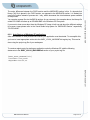
1 About This Manual
1.1
Terms and Conventions
Symbol/Tag
Description
This symbol represents important details or aspects for working
with the BSP.
Warning
Note
Filename.ext
Helpful information for working with the BSP.
This specification is used to state the complete file name with its
corresponding extension.
Examples of applications. E.g.
Instructions /
Examples
Reference
BSPa35-WinCE.UM.201
•
Specifying memory partitions
•
Processing a script
Cross-reference to another section, figure or table.
Page 5 of 58
1.2
Acronyms and Definitions
The following terminology and abbreviations are used:
BSP
Board Support Package
IDE
Integrated Development Environment
OS
Operating System
SDB
Software Development Board
HW
Hardware
OAL
OEM Adaptation Layer
OEM
Original Equipment Manufacturer
SDK
Software Development Kit
COM
Communication Ports
IRQ
Interrupt Request
BSPa35-WinCE.UM.201
BSPa35-WinCE.UM.201
Full Form
©2011 by TQ-Components GmbH
Acronym
Page 6 of 58
1.3
Liability Disclaimer
The TQ-Components GmbH does not accept guarantee of any kind about the topics, accuracy,
completeness or quality of information made available in this manual a as well as its further use.
Claims lodged against TQ-Components GmbH, related to damages of material or intellectual nature,
arising out of the use or non-use of information contained in this manual, or out of the use of incorrect
or incomplete information, would not be entertained so long as there is no evidence of intentional or
negligent fault on the part of TQ-Components GmbH.
The TQ-Components GmbH reserves the right to change or supplement the contents of this manual,
or parts of it, without prior indication to this effect.
1.4
Copyright and Licensing Costs
The drivers and utilities that are used for the components as well as the boot loader are subject to the
copyright of the respective manufacturer. Licensing conditions of the respective manufacturer should
be observed.
Licensing costs for the operating system and applications are not included and must be calculated
and stated separately.
There are no further licensing costs for general drivers or similar items.
Remarks:
Since we are dealing with an embedded system, no operating system licenses from OEM or
office/consumer sphere need to be installed.
1.5
Registered Trademarks
TQ strives to respect the copyrights of graphics used in other publications and texts, by using
graphics created by themselves or accessing license-free graphics and text.
All brand names and trademarks used in this publication are under circumstance protected by third
parties, without restriction, subject to conditions of the respective valid trademark law and ownership
law of the respective owner or proprietor. Conclusions cannot be drawn on the basis of their mere
mention that brand names and trademarks are not protected by third-party rights.
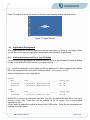
2 Introduction
The TQM Board Support Package for Windows CE 6.0 contains all necessary software components to
allow a simple and fast startup of application development with Windows CE 6.0 on your TQMa35
hardware platform.
A PC with minimum Windows XP and Microsoft Visual Studio with platform builder plug-in is necessary.
The TQMa35 BSP was created with all updates installed including the Rollup 2010 update. Please
assure that your Platform Builder installation has all these updates installed.
BSPa35-WinCE.UM.201
Page 7 of 58
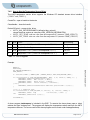
3 Contents of the CD
\---CD
©2011 by TQ-Components GmbH
|
Stand.txt
|
+---DemoImage
|
+---128MByte
|
|
NK.bin
|
|
|
\---256MByte
|
NK.bin
|
+---DemoProject
|
tqs_src_proj.zip
|
+---eBoot
|
+---128MByte
|
|
EBOOT.bin
|
|
|
\---256MByte
|
EBOOT.bin
|
+---SDK
|
tqs_sdk.msi
|
BSPa35-WinCE.UM.201
BSPa35-WinCE.UM.201
Page 8 of 58
4
Installation
The following chapters will guide you through the installation of the TQMa35 BSP for Windows CE 6.0.
We assume that you have already installed the Microsoft Visual Studio with Platform Builder plug-in
from the original Microsoft DVD or CD. If not please install it before proceeding to the next paragraph.
The installation drive should be “C:”! No newer BSP should be installed!
4.1
Installation of the Platform Builder Updates
Microsoft delivers updates to the Platform Builder monthly. The TQM BSP was created with all updates
installed including the Rollup 2010 Update. Please assure that your Platform Builder installation has all
these Updates installed.
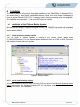
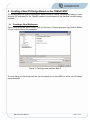
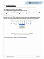
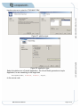
4.1.1
Which Updates are already installed
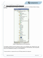
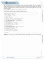
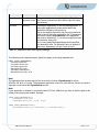
You can check for installed updates by looking in the Platform Builder update folder
(C:\WINCE600\Updates). For each installed update there should be file in HTML and Rich Text format
with detailed information about the update.
Figure 1: Rollup updates
4.1.2
How to install missing updates
All updates released by Microsoft until December 2010 may found on the Microsoft Download center
page. Please search for “Windows Embedded CE 6.0 Cumulative Product Update Rollup Package
(through 12/31/2010)” and install them.
BSPa35-WinCE.UM.201
Page 9 of 58
4.2
Installation of the BSP
During the installation the BSP the Visual Studio should be closed.
4.3
Installation of the Demo Workspaces
The demo workspaces for the TQMa35 BSP are included on the CD as “\DemoProject”. The
workspaces are a good starting point for a new OS design. They include all special drivers, the platform
options and so on.
The workspaces are located as an archive on the CD in the directory “\DemoProject”.
-
Expand the archive to “c:\wince600\OSDesigns\”
-
Browse to the “c:\wince600\TQS” folder and open the TQS.snl as a Project in the Visual Studio.
4.3.1
©2011 by TQ-Components GmbH
The BSP consists of 2 parts. One is the original BSP of Freescale found on “\Free Scale BSP” on the
CD that includes the common part of the i.MX35 and should be installed first. The second is the TQS
specific BSP, which is stored as “\SourceBSP” on the CD. This archive has to expand under the
“c:\wince600\platform” directory.
Contents of the TQMa35 _SampleWorkspace
The demo workspace “TQS” is based on the „Industrial Controller“design. For detailed information
about the included components please have a look into the project file in the folder
\OsDesign\tqs\tqs\TQS.pbxml.
4.4
Removal of a Demo wWrkspaces
Close the Visual Studio.
BSPa35-WinCE.UM.201
Page 10 of 58
BSPa35-WinCE.UM.201
Delete the appropriate demo workspace directory from the OSDesign directory of your Platform Builder
installation (e.g. c:\wince600\osdesignTQS).
5 Creating a New OS Design Based on the TQMa35 BSP
The following steps will guide you through the whole process of creating, compiling and testing of a new
Windows CE workspace for the TQMa35 hardware module based on the industrial controller design
template.
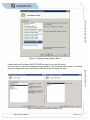
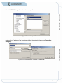
5.1
Creating a New Workspace
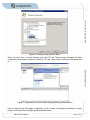
Open Visual Studio and select Project... from the File menu. Choose the project type Platform Builder
6.0 and choose name for the workspace.
Figure 2: Creating a new platform Step 2
The next dialog you should skip and then you can specify one or more BSPs on which your OS design
should be based.
BSPa35-WinCE.UM.201
Page 11 of 58
©2011 by TQ-Components GmbH
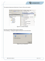
Figure 3: Creating a new platform Step 3
Please choose the FreeScale i.MX35 TQS BSP as base for your new OS design.
The next step is to choose a predefined design template of the OS design being created. You should
select the configuration, which has the best conformity to the OS design you need.
BSPa35-WinCE.UM.201
Figure 4: Creating a new platform Step 4 & 5
BSPa35-WinCE.UM.201
Page 12 of 58
We chose the Industrial Device and Industrial Controller as a base configuration for our OS design, as
this configuration includes already TCP/IP networking, GUI support and most of the programming APIs.
With the following steps various components such as applications can be added to the OS design. You
will be able to modify this configuration later on, however it will be more detailed and you will have to
deal with dependencies of the modules. The figures below show a configuration example:
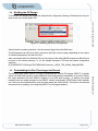
Figure 5: Creating a new platform Step 6
We deselect the .NET Compact Framework component and include the Console Window, the Network
User Interface and the Waveform Audio.
On the next tab we add the FTP and Telnet server components.
BSPa35-WinCE.UM.201
Page 13 of 58
©2011 by TQ-Components GmbH
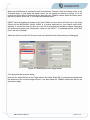
Figure 6: Creating a new platform Step 7
When you click Next, a security warning about the FTP and Telnet servers will appear as these
components allow network access to our device. FTP and Telnet security settings are discussed later
on.
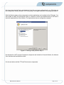
BSPa35-WinCE.UM.201
Figure 7: Appearance of Visual Studio after generating a new platform
Now you have a basic OS design configuration, which is ready for building and creating a run-time
image, but still lacks the OS design specific hardware drivers.
BSPa35-WinCE.UM.201
Page 14 of 58
5.2
How to Add Drivers and OS Components
Drivers can be added to your OS design by selecting the component in the Platform Builder’s Catalog
Item View.
Figure 8: Adding drivers and OS components
The selected component will now be shown as active in your OS Design View, otherwise with a right
click and Reasons for Exclusion of Item will show the background of the deselection. Often components
under Core Os\CEBASE are missed (i.e. for the USB device).
To remove a driver or component from your OS Design deselect the component.
BSPa35-WinCE.UM.201
Page 15 of 58
5.3
OS Design Configuration
After we added all desired components and drivers, we have to do some configuration settings before
we can build our OS design.
Debug Port Configuration
The item Debug enable includes a control panel applet to enable or disable the debug functionality. On
default the debug port is enabled!
©2011 by TQ-Components GmbH
5.3.1
Figure 9: Debug configuration
5.3.2
Touch Calibration
To avoid the touch calibration mechanism on every start the CalTouch Autostart ONCE can used to
reduce the calibration uniquely.
Hint: after calibration the tool flushreg should be used to make the calibration data persistent.
BSPa35-WinCE.UM.201
Figure 10: Touch calibration configuration
BSPa35-WinCE.UM.201
Page 16 of 58
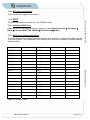
5.3.3
Build Options
To set the build options for your OS design, open the ...Properties dialog from the Project menu in
Visual Studio and go to the Build Options tab.
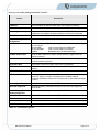
The most important options are described in table 1. There is also a recommendation given for setting
the build options for the Debug and Release configuration of your OS design.
Description
Option
Build
configuration
Debug Release
Enable eBoot Space Should be checked if you use the eBoot boot loader (normally
in Memory
used for downloading the Image from the Visual Studio)
X
X
(X)
X
Write run-time
image to flash
memory
Select between RAM and Flash image. An image on SD-Card
should be a RAM-Image.
Enable Kernel
Debugger
Allows connecting the kernel debugger of Visual Studio with the
target.
X
Enable KITL
Enables the Kernel Independent Transport Layer (KITL).
Needed for communication between the development
workstation and the target device.
X
(X)
Table 5-1: build options
In Release Builds the KITL should always be turned off as it will slow down your platform performance!
5.3.4
Language Settings
To set the default language of your OS design open the … Properties dialog from the Platform menu in
Visual Studio and go to the Locale tab.
Here you can set the locales that your OS design will support. The locales include information about
currency formats, date and time formats, etc. specific to each country.
Figure 11: Locale settings
BSPa35-WinCE.UM.201
Page 17 of 58
The default language specifies the language of the Windows CE user interface (buttons, menus,
windows, etc.).
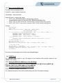
5.3.5
Environment Variables
The build process of an OS design is controlled by environment variables. In the tab Build in Open
Release Directory in Build Window you can set additional environment variables for your workspace.
To check which environment variables are set, open the release directory (Build -> Open Release
Directory in Build Window):
Use the set command to get a list of currently set environment variables for your OS design:
BSPa35-WinCE.UM.201
Page 18 of 58
BSPa35-WinCE.UM.201
Figure 12: Open Release Directory
©2011 by TQ-Components GmbH
To set the default keyboard layout, which is independent from the default language, please refer to
chapter Setting the Default Keyboard Layout.
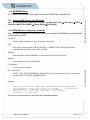
Figure 13: Viewing environment variables
Example:
If you want to set the environment variable BSP_ASYNC_FILES to include additional active
sync components, please type:
Set BSP_ASYNC_FILES=1
To delete the variable, just type:
Set BSP_ASYNC_FILES=
or IMGRAM256 to enable the second 128 Mbyte of RAM.
All changes are only in the current command active!
Alternatively you can add the environment variable in the Environment tab of the Platform
Settings dialog.
BSPa35-WinCE.UM.201
Page 19 of 58
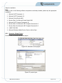
5.4
Building the OS Design
To build your OS design, first choose the desired build configuration (Debug or Release) from the pulldown menu in the Visual Studio IDE.
©2011 by TQ-Components GmbH
Figure 14: Selecting the active configuration
Second start the system generation: click the choose Sysgen from the Build menu.
The build process can take more than 5 minutes to build the run-time image, depending on the number
of included components, and the host CPU.
After a successful build, the Windows CE run-time image (a file called NK.BIN respectively NK.nb0) can
be found in the release directory, i.e. for the sample workspace TQS and the release configuration
would be:
$(_WINCEROOT)\OSDesign\TQS\TQS\RelDir\Freescale_i_MX35_TDS_ARM4I_Debug\NK.BIN
5.5
Downloading the Run Time Image via Ethernet
BSPa35-WinCE.UM.201
Page 20 of 58
BSPa35-WinCE.UM.201
The Ethernet boot loader (EBOOT) is used to download and execute OS images. EBOOT is typically
written into NOR flash memory on the TQMa35 module and executes immediately out of reset. Initially,
the target hardware will have EBOOT resident in the NOR flash memory. In addition, the target
hardware has non-volatile storage for the EBOOT network configuration (DHCP/static, MAC address,
etc.) that must be initialized before using the boot loader with Visual Studio. This section will describe
the procedure for updating, and configuring EBOOT on the target hardware.
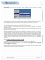
5.5.1
Connect the target
To connect the target at a minimum following connections should exist.
Network
RS232
(115200/8/1/
Power (12V)
Figure 15: Connect a target
Please examine whether after switching on the Network LED turns on.
BSPa35-WinCE.UM.201
Page 21 of 58
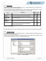
5.5.2
Configuring Ethernet Connection for Downloading and Debugging
To configure an Ethernet connection that can be used for downloading and debugging images, follow
these steps:
©2011 by TQ-Components GmbH
1. From the Visual Studio Target menu select Connectivity Options...
Then select Add Device and choose a name for your target device. In our example we choose
TDS as target device name.
Figure 16: Add a new target device name
After you clicked Add the Kernel Service Map tab will be opened automatically:
BSPa35-WinCE.UM.201
Figure 17: Target download settings
BSPa35-WinCE.UM.201
Page 22 of 58
Make sure that Ethernet is selected for both Download and Transport. Click the Settings button of the
Download option. A new dialog will appear where you can choose the device to connect to. At the
moment the Active Devices list will be empty. Now start your TQMa35 module. When the Startup menu
appears just press Space and ‘D’ to choose the download option.
EBOOT sends a broadcast message to the Visual Studio and your device will show up in the Active
Devices list as MX35XXXXX (where XXXXX is a number depending on your network card’s MAC
address). If your device does not show up in the list of active devices, precede to chapter Debugging
the download connection and Configuration Options of the EBOOT . It is possible that the option auto
boot is not set to Disabled.
Select the device and click OK. Now your device is selected for both Downloading and Debugging.
Figure 18: Selecting an active target device
Click Apply and then close the dialog.
Now you can select Attach from the Target menu in the Visual Studio IDE. A new dialog will appear and
the download of the run-time image will start. If not then reboot the TQMa35 module and wait for the
download to begin.
BSPa35-WinCE.UM.201
Page 23 of 58
©2011 by TQ-Components GmbH
Figure 19: Downloading the Runtime Image
After the download is finished Windows CE should start up on your target device. For
subsequent downloads just select again Attach from the Target menu (you don’t need to
configure the remote connection again unless you change targets).
5.5.3
Building and Downloading a Run Time Image into SDRAM Using EBOOT
To build and download a run-time image into the SDRAM of the target, follow these steps:
BSPa35-WinCE.UM.201
Page 24 of 58
BSPa35-WinCE.UM.201
1. Open the desired workspace within Visual Studio.
2. Deselect Project → ... Properties → Configuration Properties → Build Options →Write Run-time
Image to Flash Memory.
3. Build the run-time image following the steps provided in Building the OS Design.
4. Reset the TQMa35 module to launch EBOOT on the target.
5. If a target device connection has not been created within Visual Studio, follow the steps in
Configuring Ethernet Connection to establish a connection.
6. From the Visual Studio Target menu, select Attach Device to begin the download.
5.5.4
Build and Downloading a Run Time Image into NOR Flash Using EBOOT
To download a run-time image into the NOR Flash of the target, follow these steps:
1. Open the desired workspace within Visual Studio.
7. Select Deselect Project → ... Properties → Configuration Properties → Build Options →Write
Run-time Image to Flash Memory.
2. Build the run-time image following the steps provided in Chapter Building the OS Design.
3. Reset the TQMa31 module to launch EBOOT on the target.
4. If a target device connection has not been created within Visual Studio, follow the steps in
Configuring Ethernet Connection for Downloading and Debugging to establish a
connection.
5. From the Visual Studio Target menu, select Attach Device to begin the download.
6. After the download is complete, switch over to your terminal emulation application.
At this point EBOOT has downloaded the image (NK.nb0) temporarily into SDRAM and is ready
to begin the flash programming procedure.
7. In the terminal emulation application, hit the ‘y’ key to begin programming the flash.
INFO: Downloading NK NOR image.
WARNING: Flash update requested.
Do you want to continue (y/n)?
Warning:
DO NOT SWITCH OFF THE POWER SUPPLY DURING FLASH UPDATE!
8. EBOOT will program the image into flash and provide status using serial debug messages.
Once
the programming is complete, you will see the following messages:
INFO: Flashing sequence complete.
Reboot the device manually...
Spin Forever...
9. To boot the programmed image automatically follow the Instructions given in Chapter Running
an OS Image from NOR Flash using EBOOT.
5.5.5
Running a Run Time Image from NOR Flash Using EBOOT
To execute an OS image from NOR flash that has been previously programmed using the procedure
described in Downloading an OS Image into NOR Flash using EBOOT, follow these steps.
1. Reset the TQMa35 module to launch EBOOT on the target.
2. Quickly switch over to your terminal emulation application and wait for the debug message
“Press [ENTER] to download now or [SPACE] to cancel.” to appear.
3. Hit the space bar to bring up the EBOOT configuration menu.
4. Continue selecting the auto boot option of the EBOOT menu until “NK from NOR” is selected.
5. Specify the desired boot delay using the Boot Delay menu option.
6. Save the configuration using the EBOOT menu.
7. Reset the TQMa35 module to launch EBOOT again. EBOOT will automatically jump to the runtime image in NOR flash after the specified boot delay.
BSPa35-WinCE.UM.201
Page 25 of 58
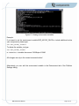
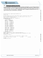
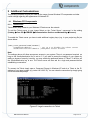
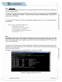
5.5.6
Debugging the download connection
INFO:OALLogSetZones: dpCurSettings.ulZoneMask: 0xb
OEM Init Done
Press [ENTER] to launch image stored in NOR flash or [SPACE] to cancel.
Initiating image launch in 3 seconds.
seconds.
Launching flash image ...
BSPa35-WinCE.UM.201
2 seconds.
1 seconds.
0
Page 26 of 58
BSPa35-WinCE.UM.201
Microsoft Windows CE Bootloader Common Library Version 1.4 Built Mar 17 2011 12:16:46
Microsoft Windows CE Ethernet Bootloader 1.0 for MX35 3DS (Mar 17 2011 12:37:16)
INFO: Bootloader launched from NOR
OALBspArgsInit: *** configFlags = 0x00000009 ***
BSP System Configuration:
L2 CACHE ENABLED
MCU PLL = 532000000 Hz
PER PLL = 300000000 Hz
ARM CLOCK = 532000000 Hz
AHB CLOCK = 133000000 Hz
IPU CLOCK = ~133000000 Hz
MLB CLOCK = 266000000 Hz
IPG CLOCK = 66500000 Hz
PER CLOCK = 66500000 Hz
SSI1 CLOCK = 100000000 Hz
SSI2 CLOCK = 100000000 Hz
CSI CLOCK = 100000000 Hz
ESDHC1 CLOCK = 100000000 Hz
ESDHC2 CLOCK = 100000000 Hz
ESDHC3 CLOCK = 100000000 Hz
SPDIF CLOCK = 100000000 Hz
USB CLOCK = 60000000 Hz
UART CLOCK = 100000000 Hz
NFC CLOCK = 22166666 Hz
no sd-card present !
WARNING: OEMPlatformInit: Failed to initialize SDHC device.
INFO: Reading boot configuaration in NOR flash (addr = 0xB1FE0000, size = 0x5C)
System ready!
Preparing for download...
©2011 by TQ-Components GmbH
If you have problems with connecting your device through Visual Studio, you can observe through a
serial connection if the initiation of the network card by the boot loader works well. In order to do so,
connect the UART1 port of your TQMa35 module with a serial port of your host computer by means of
a null modem cable. Use the program C:\WINCE600\PUBLIC\COMMON\OAK\BIN\I386\ceterm.exe, or
HyperTerminal to open a connection at 115200/8/N/1.
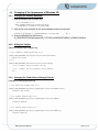
6 EBOOT Boot Loader
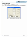
6.1
Configuration Options of the EBOOT Boot Loader
First you have to configure one COM port of your development computer with following parameters
(115200/8/N/1) as shown:
Figure 20: COM port configuration for EBOOT boot loader
BSPa35-WinCE.UM.201
Page 27 of 58
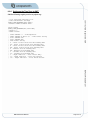
After that, when the device is powered up and you have connected UART1 port of your TQMa35
module with a serial port of your development computer by means of a null modem cable, you can
enter the configuration menu by hitting the SPACE key in your terminal program when you see the
following message:
Hitting SPACE will bring up the boot loader configuration menu:
----------------------------------------------------------------------------Freescale iMX SOC Menu Item
----------------------------------------------------------------------------[0] IP Address : 0.0.0.0
[1] Set IP Mask : 0.0.0.0
[2] Boot Delay : 3
[3] DHCP : Enabled
[4] Reset to Factory Default Configuration
[5] Select Boot Device : NK from NOR
[6] Set MAC Address FEC : 0-13-45-12-33-12
[7] Set MAC Address SMSC : 4-3-2-1-30-82
[9] Bootloader Shell
[I] KITL Work Mode : Interrupt
[K] KITL Enable Mode : Disable
[P] KITL Passive Mode : Disable
[S] Save Settings
[D] Download Image Now
[L] Launch Existing Flash Resident Image Now
[E] Select Ether Device : FEC
[M] MMC and SD Utilities
[G] L2CC Active Mode : Enable
[W] L2CC Work Mode : WriteBack
©2011 by TQ-Components GmbH
Press [ENTER] to download now or [SPACE] to cancel.
Selection:
BSPa35-WinCE.UM.201
Page 28 of 58
BSPa35-WinCE.UM.201
If no output is shown on your terminal, please check the serial cable (crossed ??) and the power
supply.
Here you can modify settings described in table 2.
Option
Description
IP Address
Select IP address for the boot loader (Not used if DHCP is enabled).
Subnet Mask
Select subnet mask for the boot loader (Not used if DHCP is enabled).
Boot delay
Delay in seconds that the boot loader waits for the SPACE key to enter in the
configuration menu before the option selected in “Auto boot” is executed.
DHCP
Enable/disable DHCP for the boot loader
Reset to Factory Default
Configuration
Reset all setting to the factory defaults.
Auto boot
Select the boot option for normal startup (if not entered boot configuration).
You can choose:
NK from NOR
Load run-time image from NOR flash
NK from SD/MMC
Load run-time image from SDCard.
Disabled
Bootloader will try to download image
Set MAC Address FEC
Select the MAC address for i.MX35 network interface. (Upper slot of the
network connector)
Set MAC Address SMSC
Select the MAC address for the onboard SMSC network interface. (Lower
slot of the network connector)
Bootloader Shell
Some helper functions to modify similar memory addresses.
KITL Work Mode
If KITL is active the network adapter may be used as a polled or interrupt
interface.
KITL Enable Mode
Enable/Disable KITL
KITL Passive Mode
Switch between active and passive KITL.
Active KITL will try to connect a Visual Studio to establish a debug
connection via Ethernet. Passive KITL will just print out the debug messages
to UART1.
Save configuration
Saves the current configuration to NOR flash.
Download image now
Immediately starts a download connection to load a run-time image from
Visual Studio.
Launch Existing Flash
Resident Image Now
Launch the run-time image stored already in NOR flash.
Select Ether Device
Select the Ethernet device for eBoot (FES or SMSC)
MMC and SD Utilities
Some utilities to write / format to the eMMC Flash and SD-Card
L2CC Active Mode
Enable / Disable L2-Cache
L2CC Work Mode
L2 write strategy: write back / write trough
Table 6-1: Bootloader options
BSPa35-WinCE.UM.201
Page 29 of 58
6.2
Updating the EBOOT boot loader
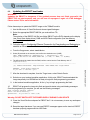
Follow these steps to update the EBOOT image on the TQMa35 module:
1. Use the File menu of Visual Studio and choose Open Workspace.
2. Select the appropriate EBOOT.NB0 file you received from TQ.
Note:
The selection of the EBOOT.nb0 file (see folder \EBOOT on the DVD) depends on the display
(see Direct Draw display driver), RAM and NOR-Flash configuration (see also Memory
configuration).
©2011 by TQ-Components GmbH
WARNING:
Updating the EBOOT is dangerous. If the updated process does not finish successful, the
EBOOT will not start anymore, and you will have to reprogram it again via JTAG debugger.
Please contact TQ for more information.
3. Follow the steps in Configuring Ethernet Connection for Downloading and Debugging to
establish an Ethernet connection between the target and Visual Studio.
4. From the Target menu, select Attach Device.
5. Select (D)ownload on the terminal, and confirm the destination as 1 (NOR)
INFO: OEMMultiBINNotify (dwNumRegions = 1, dwRegionStart = 0x0).
Specify destination for EBOOT/SBOOT NB0 [1 = NOR, 2 = NAND, 3 = SD/MMC]:
6. The eBoot should be loaded into the RAM, confirm to write into the Flash-Memory with “Y”
Completed file(s):
------------------------------------------------------------------------------[0]: Address=0x90000000 Length=0x40000 Name="EBOOT.nb0" Target=FLASH
7. After the download is complete, from the Target menu, select Detach Device.
8. Switch over your terminal emulation application. At this point, EBOOT has downloaded the
image temporarily into SDRAM and is ready to begin the flash programming procedure.
9. In the terminal emulation application, hit the ‘y’ key to begin programming the flash.
10.
EBOOT will program the image into flash and provide status using serial debug messages.
Once the programming is complete, you will see the following messages:
INFO: Flashing sequence complete.
Reboot the device manually...
SpinForever...Do you want to reset [Y\N]
Warning: DO NOT SWITCH OFF THE POWER SUPPLY DURING FLASH UPDATE
11. Close the Visual Studio workspace for EBOOT.nb0. It is not necessary to save any workspace
changes.
12. Reset the target hardware. If you see new EBOOT messages appear on the terminal, EBOOT
has been properly programmed into NOR flash.
BSPa35-WinCE.UM.201
Page 30 of 58
BSPa35-WinCE.UM.201
WARNING: Flash update requested.
Do you want to continue (y/n)?
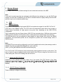
7 Device Drivers
This chapter describes the individual settings for the included device drivers of the BSP.
Note:
If you want to create more than one workspace with different driver settings (e.g. one with DHCP and
another one with static IP-Address) you will have to relocate the driver registry settings from the BSP
(platform.reg) to your workspace (project.reg).
7.1
7.1.1
USB
USB OTG Drivers
The USB OTG driver provides high speed USB 2.0 host and device support for the USB “On The Go”
(OTG) port of the TQMa35 module. The OTG driver will automatically select either Host (master) or
Device (slave) functionality for high speed at any given time, depending on the USB OTG-Pin
configuration.
This is achieved by the set of three drivers: USB OTG host controller driver, USB client driver and/or
USB transceiver controller (“Full Function”) driver, which performs the host/function client switching.
The USB host driver can be configured for class support for mass storage, HID, printer, and RNDIS
peripherals. The device/client portion can be configured to provide one of mass storage, serial, or
RNDIS function.
Note:
The USB OTG port can only be configured in one of the 3 possible device roles (mass storage, serial or
RNDIS). The role is set with “DefaultClientDriver” value under the
[HKEY_LOCAL_MACHINE\Drivers\USB\FunctionDrivers] key.
The “Full Function” OTG transceiver driver automatically selects between the host or client driver. The
host or client can also be configured as the only mode for the OTG port, using the Pure Host or Pure
Client catalog item. All the OTG catalog items are exclusive.
7.1.1.1 Adding the USB OTG Drivers
Depending on the desired functionality select one of the entries Full OTG Function, Pure Client
Function or Pure Host Function in the Catalog (Catalog Item View Æ Third party Æ BSPs Æ
Freescale i.MX35 TQS: ARMV4I Æ Device Drivers Æ USB Devices Æ USB High Speed OTG
Device).
7.1.1.2 USB OTG Drivers Configuration
There is nothing to configure for this driver.
BSPa35-WinCE.UM.201
Page 31 of 58
7.1.2
USB Mouse and Keyboard Support
To have support for USB keyboards and mice add the “USB HID Keyboard and Mouse” component to
your OS design (Catalog Item View Æ Core OS Service Æ USB Host Support -> USB Human Input
Device (HID) Class Driver -> USB HID Keyboard and Mouse).
USB Printer Support
To have support for USB printers add the components “USB Printer Class Driver” (Catalog Item View
Æ CoreOS Æ CEBASE Æ Core OS Service Æ USB Host Support) and "PCL Printer Driver”
(Catalog Item View Catalog Æ Device Drivers Æ Printer Devices) to your OS design.
7.2
SD Host Controller
The SD Host Controller Driver adds support for SD-Card functions of the i.MX35 CPU to your OS
design.
7.2.1
©2011 by TQ-Components GmbH
7.1.3
Adding the SD Host Controller Driver to Your OS Design
Select the Enhanced SD Host Controller 1 or eMMC Memory at SD3 component in the Catalog
(Catalog Item View Æ Third party Æ BSPs Æ Freescale i.MX35 TQS: ARMV4I Æ Device Drivers
Æ SD Controller).
7.2.2
SD Host Controller Driver Configuration
The device specific parameters i.e. the name of the directory entries are stored in
\drivers\esdhc\esdhc_mx35.reg.
7.3
Audio
7.3.1
Adding the Audio Driver to Your OS Design
Select the Audio Buzzer and/or SGTL5000 Stereo Audio component in the Catalog (Catalog Item View
Æ Third party Æ BSPs Æ Freescale i.MX35 TQS: ARMV4I Æ Device Drivers Æ Audio).
7.3.2
SGTL5000
The SGTL5000 Stereo Audio supports recording and playing audio data. The correct handling of the
standard interface is described at the WinCE help. To support the different audio formats enable the
codecs at Catalog Item View Æ CoreOS Æ CEBASE Æ Core OS Service Æ Graphics and
Multimedia Technologies.
To test the SGTL5000 Stereo Audio may the used the application testwavein.exe located at \windows
directory of the device. The application records 8 seconds from the line in into the file \test.wav.
Subsequently the file is played.
BSPa35-WinCE.UM.201
Page 32 of 58
BSPa35-WinCE.UM.201
The Audio Driver adds support for the audio functions of the i.MX35 CPU to your OS design.
7.3.3
Buzzer
The „Audio Buzzer“ is a simple PWM generator without any volume control. The driver is implemented
as a stream interface device called BUZ1:.
CreateFile – open a handle to the device
CloseHandle – close the handle
DeviceIOControl – access to the driver
• IOCTL_XXX_GETVERSIONINFO (defined at bsp_verion.h)
returns the driver version as a structure DRV_VERSION_INFORMATION
• IOCTL_BUZ_SET starts a tone generation, the frequency and duration defined at the structure
DRV_BUZZER. The caller of this IO-Controls is blocked until the tone generation is stopped !
Example:
HANDLE h = CreateFile(L"BUZ1:", GENERIC_READ | GENERIC_WRITE,0,NULL,OPEN_EXISTING,0,NULL);
if ( DeviceIoControl(h, IOCTL_XXX_GETVERSIONINFO, NULL, 0, &v, sizeof(v), &dummy, 0) ) {
RETAILMSG(1,(TEXT("Versionsinformation:\r\n")));
RETAILMSG(1,(TEXT("
Name: %S\r\n"), v.cName));
RETAILMSG(1,(TEXT("
Build: %S\r\n"), v.cBuild));
RETAILMSG(1,(TEXT("
Version: 0x%x\r\n"), v.ulVersion));
} else {
RETAILMSG(1,(TEXT("Versionsinformation kann nicht gelesen werden !!!!\r\n")));
}
p.freq, = 1000;
// Ton von 1 Khz
p.length = 1000;
// Laenge 1 sek
DeviceIoControl(h, IOCTL_BUZ_SET, &p, sizeof(p), NULL, 0, NULL, 0);
CloseHandle(h);
To test the buzzer you can use the test application (\windows\)testpwm.exe. The source code is of the
test application is located at \testappl\testpwm.
Syntax (calling in a telnet session):
testpwm <frequency Hz> <duration msek>
7.4
LM75 Temperature Sensor
The temperature sensor driver adds support for reading the temperature from 2 temperature sensors.
The sensor 1 is located on the rear side of the TQMa35 CPU module, and the sensor 2 is located on
the baseboard. The driver is done as a stream interface device, for each sensor one instance.
Temperatures are given as 16bit signed values in units of 0.1°C.
Note:
Adding the temperature sensor driver also adds the I2C driver to your OS design.
7.4.1
Adding the Temperature Sensor Driver to Your OS Design
Select the „ LM75 Temperature Sensor “ component in the Catalog (Catalog Item View Æ Third party
Æ BSPs Æ Freescale i.MX35 TQS: ARMV4I Æ Device Drivers Æ I2C Devices Æ Temp).
BSPa35-WinCE.UM.201
Page 33 of 58
7.4.2
How to Use the Temperature Sensor Driver
The LM75 temperature sensor driver supports the Windows CE standard stream driver interface
(“TMP1:” and „TMP2:“).
CloseHandle – close the handle
DeviceIOControl – access to the driver
• IOCTL_XXX_GETVERSIONINFO (defined at bsp_verion.h)
returns the driver version as a structure DRV_VERSION_INFORMATION
• IOCTL_GET_TEMP read one value from the temperature IC (structure TEMP_STRUCT)
• IOCTL_SET_TEMP write one value from the temperature IC (structure TEMP_STRUCT)
reg
R/W
Value
Bezeichnung
0
R
temperature * 10°C ( value 550 corresponds 55,0 °C )
Temperature
1
R/W
Zu schreibender Registerwert
Config
2
R/W
temperature * 10°C (value 550 corresponds 55,0 °C )
THYST
3
R/W
temperature * 10°C ( value 550 corresponds 55,0 °C )
TOS
©2011 by TQ-Components GmbH
CreateFile – open a handle to the device
Table 7-1: LM75 Register
Example
h = CreateFile(L"TMP1:", GENERIC_READ | GENERIC_WRITE,0, NULL,OPEN_EXISTING,0,NULL);
if ( DeviceIoControl(h, IOCTL_XXX_GETVERSIONINFO, NULL, 0, &v, sizeof(v), &dummy, 0) ) {
RETAILMSG(1,(TEXT("Versionsinformation:\r\n")));
RETAILMSG(1,(TEXT("
Name: %S\r\n"), v.cName));
RETAILMSG(1,(TEXT("
Build: %S\r\n"), v.cBuild));
RETAILMSG(1,(TEXT("
Version: 0x%x\r\n"), v.ulVersion));
} else {
RETAILMSG(1,(TEXT("Versionsinformation kann nicht gelesen werden !!!!\r\n")));
}
t.reg = 0; // Temperatur lesen
if ( DeviceIoControl(h, IOCTL_GET_TEMP, &t, sizeof(t), &t, sizeof(t), &dummy, 0) )
RETAILMSG(1,(TEXT(" Temp
= %d *10°C\r\n"), t.value ));
else
RETAILMSG(1,(TEXT("Fehler !!\r\n")));
CloseHandle(h);
A demo program testtemp.exe is included in the BSP. To execute the demo please open a telnet
window and type “testtemp.exe”. The program will display the temperature values read from the LM75
temperature sensors. The source code of this demo program can be found under \testappl\testtemp.
BSPa35-WinCE.UM.201
Page 34 of 58
BSPa35-WinCE.UM.201
HANDLE h;
DWORD dummy;
DRV_VERSION_INFORMATION v;
TEMP_STRUCT t;
7.5
Serial Ports (UARTs)
Serial ports (one RS232, one RS485) are used e.g. for debug or to connect external devices.
7.5.1
Adding Serial Drivers to Your OS Design
You can add up to three serial ports through the Visual Studio IDE.
Select „UART1 “ and/or “UART2” component in the catalog (Catalog Item View Æ Third party Æ
BSPs Æ Freescale i.MX35 TQS: ARMV4I Æ Device Drivers Æ Serial).
7.5.2
Serial Driver Configuration
Because the serial UART1 is also used as debug interface a control panel applet dbgena.cpl is included
in the BSP. After enable / disable the debug interface the registry should make persistent (flushreg).
Figure 21: Enable or disable debug port
The source code of the CPL can be found under \testappl\dbgena
BSPa35-WinCE.UM.201
Page 35 of 58
7.6
Touch Panel Support
The BSP includes a driver for the i.MX35 integrated 4-wire resistive touch controller.
Adding the Touch Panel Driver
Select touch panel driver on the ”Touch Driver” component in the (Catalog Item View Æ Third party Æ
BSPs Æ Freescale i.MX35 TQS: ARMV4I Æ Device DriversÆ Touch).
7.6.2
Touch Panel Driver Configuration
The configuration is done by calling caltouch or caltouchauto. By default the caltouch is replaced by
caltouchauto and run on system start if no calibration data stored in registry.
The source code of both applications can be found under \testappl\caltouch*.
7.7
©2011 by TQ-Components GmbH
7.6.1
I2C Bus Driver
The Inter-Integrated Circuit (I2C) module provides the generic functionality of a standard I2C slave and
master. The I2C module is designed to be compatible with the standard Phillips I2C bus protocol.
7.7.1
Adding the I2C Bus Driver
Select one or both of the “I2C bus <x>” component in the (Catalog Item View Æ Third party Æ BSPs
Æ Freescale i.MX35 TQS: ARMV4I Æ Device DriversÆ I2C Bus).
7.7.2
I2C Bus Driver Configuration
There is nothing to configure for this driver.
GPT driver
The general-purpose timer is a multipurpose module used to measure intervals or generate periodic
output.
7.8.1
Adding the GPT Driver
Select the “GPT” component in the (Catalog Item View Æ Third party Æ BSPs Æ Freescale i.MX35
TQS: ARMV4I Æ Device DriversÆ GPT).
7.8.2
GPT Driver Configuration
There is nothing to configure for this driver.
BSPa35-WinCE.UM.201
Page 36 of 58
BSPa35-WinCE.UM.201
7.8
7.9
Smart Backlight Control
The backlight driver interfaces with the Windows CE Power Manager to provide timed control over the
display backlight. A timeout interval controls the length of time that the backlight stays on.
7.9.1
Adding Smart Backlight Control
Select the IPU Backlight Control Support on the appropriate driver component in the (Catalog Item
View Æ Third party Æ BSPs Æ Freescale i.MX35 TQS: ARMV4I Æ Device DriversÆ IPU
Backlight).
7.9.2
IPU Backlight Driver Configuration
The following registry keys are required to properly load backlight driver.
[HKEY_CURRENT_USER\ControlPanel\Backlight]
"BattBacklightLevel"=dword:FF ; Backlight level settings. 0xFF = Full On
"ACBacklightLevel"=dword:FF
; Backlight level settings. 0xFF = Full On
; Backlight control default settings for WinCE.
"UseExt"=dword:0
; Enable timeout when on external power
"UseBattery"=dword:0
; Enable timeout when on battery
"AdvancedCPL"="AdvBacklight" ; Enable Advanced Backlight control panel dialog
"BatteryTimeout"=dword:1E
; 30 Seconds
"ACTimeout"=dword:78
; 2 Minutes
The timeouts are given in seconds. On a running Windows CE the backlight setting can also changed
by the display control panel applet.
Figure 22: Backlight Control
Hint: Don’t forget to make the change persistent by calling flushreg c.
7.10 RTC
The RTC driver adds the real-time clock support to your OS design.
7.10.1 Adding the RTC driver
Select RTC driver on the RTC component in the (Catalog Item View Æ Third party Æ BSPs Æ
Freescale i.MX35 TQS: ARMV4I Æ Device DriversÆ RTC).
BSPa35-WinCE.UM.201
Page 37 of 58
7.10.2 RTC driver configuration
There is nothing to configure for this driver.
The GPIO driver drives the buzzer pin of the TQMa35 module.
7.11.1 Adding the GPIO driver
Select the GPIO on the appropriate driver component in the (Catalog Item View Æ Third party Æ
BSPs Æ Freescale i.MX35 TQS: ARMV4I Æ Device DriversÆBuzzer).
7.11.2 GPIO driver default configuration
The GPIO driver uses a standard Windows CE stream driver interface. To access to the driver use the
IO-Control interface. The configuration of the similar pins is done by the software. By default following
states are active:
Value
IC / PIN
Initial value
I/O
GPOUT1
0
D24/P0
0
O
GPOUT2
1
D24/P1
0
O
GPOUT3
2
D24/P2
0
O
GPOUT4
3
D24/P3
0
O
GPOUT5
4
D24/P4
0
O
GPOUT6
5
D24/P5
0
O
GPOUT7
6
D24/P6
0
O
GPOUT8
7
D24/P7
0
O
GPI1
8
D24/P0
X
I
GPI2
9
D26/P1
X
I
GPI3
10
D26/P2
X
I
GPI4
11
D26/P3
X
I
USER_LED1
12
D26/P4
0
O
USER_LED2
13
D26/P5
0
O
LD_BKL_ON
14
D26/P6
0
O
LCD_LVDS_ENA
15
D26/P7
0
O
OVERTEMP
16
GPIO1_12
X
I
BSPa35-WinCE.UM.201
Pin name
Table 7-2: Default states
BSPa35-WinCE.UM.201
©2011 by TQ-Components GmbH
7.11 GPIO
Page 38 of 58
7.11.3 How to use the GPIO driver
The GPIO driver is included as GPI1:.
CreateFile – open a handle to the device
CloseHandle – close the handle
DeviceIOControl – access to the driver
• IOCTL_XXX_GETVERSIONINFO (defined at bsp_verion.h)
returns the driver version as a structure DRV_VERSION_INFORMATION
• IOCTL_GET_LEVEL read one pin (structure GPIO_LEVEL defined at bsp_gpio.h)
• IOCTL_SET_LEVEL write one pin (structure GPIO_LEVEL defined at bsp_gpio.h)
Example:
GPIO_LEVEL gpio;
DWORD dummy;
HANDLE h = CreateFile(L"GPI1:", GENERIC_READ | GENERIC_WRITE,0,
NULL,OPEN_EXISTING, 0,NULL);
if ( DeviceIoControl(h, IOCTL_XXX_GETVERSIONINFO, NULL, 0, &v, sizeof(v), &dummy, 0) ) {
RETAILMSG(1,(TEXT("Versionsinformation:\r\n")));
RETAILMSG(1,(TEXT("
Name: %S\r\n"), v.cName));
RETAILMSG(1,(TEXT("
Build: %S\r\n"), v.cBuild));
RETAILMSG(1,(TEXT("
Version: 0x%x\r\n"), v.ulVersion));
} else {
RETAILMSG(1,(TEXT("Versionsinformation kann nicht gelesen werden !!!!\r\n")));
}
// Schalte USER-LED1 ein
gpio.pin = USER_LED1; // pin 12
gpio.level = 1; // an
DeviceIoControl(h, IOCTL_SET_LEVEL, &gpio, sizeof(gpio), NULL, 0, NULL, 0);
// Lese Pegel von IN1
gpio.pin = GPI1; // IC2, PIN 0
DeviceIoControl(h, IOCTL_GET_LEVEL, &gpio, sizeof(gpio), &gpio,
RETAILMSG(1,(TEXT(“Pegel = 0x%x\r\n”), gpio.level));
CloseHandle(h);
sizeof(gpio), &dummy, 0)
The source of a test program can be found under \testappl\testgpio.
7.12 CAN Driver
The CAN driver adds support to your OS design for the Freescale CAN controller located on the
TQMa35 CPU module .
7.12.1 Adding the MCP2515 CAN Driver to Your OS Design
Select one or both CAN interfaces in the catalog (Catalog Item View Æ Third party Æ BSPs Æ
Freescale i.MX35 TQS: ARMV4I Æ Device DriversÆ CAN).
7.12.2 Freescale CAN Driver Configuration and Usage
There is nothing to configure for this driver.
For a detailed description of the CAN interface please look on the Freescale homepage.
BSPa35-WinCE.UM.201
Page 39 of 58
7.13 EEPROM Driver
The TQMa35 EEPROM driver adds support for access the EEPROM as a standard file.
Select the EEPROM driver component in the catalog (Catalog Item View Æ Third party Æ BSPs Æ
Freescale i.MX35 TQS: ARMV4I Æ Device DriversÆI2C Devices).
7.13.2 EEPROM Driver Configuration and Usage
There is nothing to configure for this driver. All functions concerning the EEPROM are controlled via the
stream interface at EPR1.
CreateFile
Open a handle to the device, up to 10 instances may open.
©2011 by TQ-Components GmbH
7.13.1 Adding the EE Driver to Your OS Design
Seek
Move the read/write-pointer (FILE_END/FILE_CURRENT/FILE_BEGIN) for the next
command and returns the current “file” position.
WriteFile
Write the buffer into the EEPROM. A wrap around is blocked by the driver.
ReadFile
Read a number of bytes into the buffer.
CloseHandle
Close the current instance.
IOCTL_XXX_GETVERSIONINFO (defined at bsp_verion.h) returns the driver version at the
structure DRV_VERSION_INFORMATION.
Example:
HANDLE h = CreateFile(L"EPR1:", GENERIC_READ | GENERIC_WRITE,0,NULL,OPEN_EXISTING,0,NULL);
printf ("EEPROM-Size: %d \r\n", SetFilePointer(h, 0, 0, FILE_END ) ); // lese Eprom-Groesse
SetFilePointer(h, 0, 0, FILE_BEGIN ); // Lese/Scheibzeiger auf Pos 0
BOOL bRet = ReadFile ( h, test, 1024, &dwRead, NULL); // Lese 1024 Bytes
CloseHandle(h); // Schliesse Handle
The source of a test program can be found under \testappl\testeeprom.
BSPa35-WinCE.UM.201
Page 40 of 58
BSPa35-WinCE.UM.201
DeviceIOControl
7.14 SPI Bus Driver
The SPI module provides the generic functionality of a standard SPI slave and master. The SPI module
is designed to be compatible with the standard SPI bus protocol.
7.14.1 Adding the SPI Bus Driver
Select one or both of the “CSPI bus <x>” component in the (Catalog Item View Æ Third party Æ
BSPs Æ Freescale i.MX35 TQS: ARMV4I Æ Device DriversÆ CSPI Bus).
7.14.2 CSPI Bus Driver Configuration
There is nothing to configure for this driver.
8 Developing Applications
The following steps guide you through the creation of an SDK for your OS design and shows you how
to use Visual Studio 2005 to develop, debug and download applications.
8.1
Creating an SDK from Your OS Design
Note:
Before building the SDK please do a Sysgen of a Release Run-Time Image of your OS Design.
Start the Visual Studio IDE, open your workspace and select “Add New SDK” from the “Project” menu.
Figure 23: Create a new SDK
BSPa35-WinCE.UM.201
Page 41 of 58
Choose a unique name for the SDK, enter the name of your company and hit Ok.
©2011 by TQ-Components GmbH
Figure 24: Setting up the SDK properties
To finally build the SDK select Build All SDKs... from the Build menu.
Your SDK will be created as an MSI file located at: $(_PBWORKSPACEROOT)\SDK\. It is self-installable
by double clicking it and it is removable using Add/Remove Programs from the Windows XP Control
Panel.
8.2
Developing with Visual Studio 2005
8.2.1
Installation
Additionally to the installation DVD of Microsoft Visual Studio 2005 the following software components
must be on-hand or installed:
-
Microsoft .NET Framework 1.1
-
Microsoft .NET Framework 2.0
-
Service Pack 1 for Microsoft Visual Studio 2005
-
Microsoft .NET Compact Framework 2.0
-
Service Pack 1 for Microsoft .NET Compact Framework 2.0
-
Service Pack 2 for Microsoft .NET Compact Framework 2.0
-
i.MX35 TQS SDK
-
Microsoft Windows Mobile Device Center or Active Sync
BSPa35-WinCE.UM.201
Page 42 of 58
BSPa35-WinCE.UM.201
To develop and debug programs written in C++, C# and Visual Basic to run with Windows CE, you can
use Microsoft Visual Studio 2005®.
Steps for installation:
Note:
If one or more of the following software components are already installed, please skip the appropriate
installation:
1. Microsoft .NET Framework 1.1
2. Microsoft .NET Framework 2.0
3. Microsoft Visual Studio 2005
4. Service Pack 1 for Microsoft Visual Studio 2005
5. Microsoft .NET Compact Framework 2.0
6. Service Pack 1 for Microsoft .NET Compact Framework 2.0
7. Service Pack 2 for Microsoft .NET Compact Framework 2.0
8. i.MX35 TQS SDK
9. Microsoft Windows Mobile Device Center or Active Sync
8.2.2
Generate a Simple Project
Run the visual studio and select a new project
Figure 25: Generate a new project
Figure 26: project type
BSPa35-WinCE.UM.201
Page 43 of 58
Use the next menu to select the “TQS iMX35” SDK.
©2011 by TQ-Components GmbH
Figure 27: platform type
BSPa35-WinCE.UM.201
Figure 28: application type
Select the platform as a Console Application. The Visual Studio generates a simple
Application, to see something on the target add
MessageBox(NULL, L"World", L"Hello", MB_OK);
to the source code:
BSPa35-WinCE.UM.201
Page 44 of 58
Figure 29: first Application
8.2.3
Establish a Connection between VS 2005 and the CE Device
8.2.3.1 Startup over Active Sync / Transport over Ethernet
Note:
Before you start with the following steps, be sure that the run time image on the target device did built
in the active sync support (see chapter Establish a ActiveSync Connection over USB).
Click on Tools, Options on the main menu.
Figure 30: Device Options
BSPa35-WinCE.UM.201
Page 45 of 58
Select the SDK OS design from Show devices for platform.
©2011 by TQ-Components GmbH
Figure 31: selection platform device
Configure the IP address of the target depends from the network infrastructure (Properties Æ
Configure).
BSPa35-WinCE.UM.201
Figure 32:configure the IP address of the target
BSPa35-WinCE.UM.201
Page 46 of 58
Then attach to the device with the button Connect to Device on the toolbar.
Figure 33: connect to Device
Hint: Not ever the iMX35 TQS is selected as default !
The Connecting… message box appears and reports the connection status.
Figure 34: try to Connection
BSPa35-WinCE.UM.201
Page 47 of 58
Afterwards you can start with debugging by clicking on the button Start debugging (green arrow).
©2011 by TQ-Components GmbH
Figure 35: start Debugging
Set a debug break on the line MessageBox and press Run on the toolbar.
BSPa35-WinCE.UM.201
Figure 36: signaling an active breakpoint
BSPa35-WinCE.UM.201
Page 48 of 58
Press F10 (step over) and on the target you will see a small message window with Hello World.
Figure 37: target Window
8.3
Application Deployment
This chapter shows how to include applications and associated files (e.g. DLLs) in your image. Further
you will learn how to start your applications automatically when Windows CE has booted.
8.3.1
Adding Applications and Files to Your OS Design
You can include your applications and additional files (e.g. DLLs) in your Windows CE image by adding
an entry in the MODULES/FILES section of your project.bib file.
E.g. : Include an application named myapp.exe with an additional DLL named myapp.dll and a bitmap
file. In this example all files are located in a directory called %_WINCEROOT%\MYAPP\.
Add the following lines to your project.bib file:
MODULES
; Name
; -------------MYAPP.EXE
MYAPP.DLL
Path
-------------------------------------$(_Winceroot)\MYAPP\MYAPP.EXE
$(_Winceroot)\MYAPP\MYAPP.DLL
Memory Type
----------NK SH
NK SH
FILES
; Name
; -------------PLASH.BMP
Path
-------------------------------------$(_Winceroot)\MYAPP\PIC1.BMP
Memory Type
----------NK SH
MODULES is reserved for executables and DLLs. Any file in the MODULES area will be fixed up to
execute in place (XIP). Those files won't be available via the file system. This is recommended
especially for DLLs.
All files loaded by applications should be placed in the FILES section. Those files are compressed and
available via the file system.
BSPa35-WinCE.UM.201
Page 49 of 58
The major difference between the FILES section and the MODULES section is this: If a dynamic-link
library (.dll) file is placed in the FILES section, as opposed to the MODULES section, it is loaded into
every slot location instead of process slot 1 only, which decreases the virtual address space available
to the process.
If you want to learn more about how the Windows CE image is built up and about the different settings
for memory types please refer to the Visual Studio help system for “MODULES Section” respectively
“FILES Section”.
8.3.2
Auto Start-up of Windows CE applications
After the Windows CE boot process has finished, your application must be started. To accomplish this,
you have to insert appropriate entries into the HKEY_LOCAL_MACHINE\init registry key. This can be
done using the project.reg file of your workspace.
©2011 by TQ-Components GmbH
You can also rename files via the BIB file entries. As you can see in the example above, the bitmap file
called PIC1.BMP will show up as SPLASH.BMP in the Windows CE file system.
To create a registry entry for starting an application under the Windows CE, add the following
statements to the HKEY_LOCAL_MACHINE\init section of your project.reg file:
[HKEY_LOCAL_MACHINE\init]
"launchXX"="exe_name"
"dependXX"=hex:YY,00
BSPa35-WinCE.UM.201
BSPa35-WinCE.UM.201
Page 50 of 58
Name
launchXX
Values
Description
XX represents a number in decimal from 00 to 99.
Name of the
application to start. Only launch numbers from 80 to 89 are valid. All others
are reserved.
dependXX
hex:xx,yy
Describes a dependency of the launched application. If
some other application must be started before the
application defined by the launch key
can be successfully launched, then this entry should be
used to identify that other application. XX,YY represents
the launch number in hexadecimal of the application
that must be loaded first. (YY is the most significant byte
and therefore always 00).
One or more dependent applications can be specified
per dependXX value The dependXX entry is optional; if
there is no dependency you don’t need to use it.
Table 8-1 Application auto start registry settings
The following code example shows a typical Init registry entry using dependencies:
[HKEY_LOCAL_MACHINE\Init]
"Launch10"="shell.exe"
"Launch20"="device.exe"
"Launch30"="gwes.exe"
"Depend30"=hex:14,00
"Launch50"="taskman.exe"
"Depend50"=hex:14,00, 1e,00
Note:
The application that must be started, first must call the function SignalStarted() to inform
Windows CE when it is ready. The dependent application cannot run until after the function on which it
depends on has issued the SignalStarted function.
Note:
If your application is located on a external media (CFCard, USB stick) you have to add the path to this
media to the system path variable. Example:
[HKEY_LOCAL_MACHINE\init]
"Launch80"="test.exe"
"Depend80"=hex:14,00, 1e,00, 32,00
[HKEY_LOCAL_MACHINE\Loader]
"SystemPath"=multi_sz:"\\Release\\","\\cfcard\\test\\"
BSPa35-WinCE.UM.201
Page 51 of 58
8.4
8.4.1
ActiveSync
Required Components
The following components of the catalog must be added to your OS design:
©2011 by TQ-Components GmbH
1. Core OS / Windows CE devices / Applications – End User / File Sync
Figure 38: adding file sync to an OS design
2. Core OS / Windows CE devices / Shell and User Interface / Network User Interface
BSPa35-WinCE.UM.201
Figure 39: Adding Network User Interface to an OS design
BSPa35-WinCE.UM.201
Page 52 of 58
In additional following (old) components add to the platform.bib:
IF BSP_ASYNC_FILES
ConManClient2.exe $(_WINCEROOT)\PLATFORM\imx35-tqs\files\async\ConManClient2.exe NK N
cmaccept.EXE $(_WINCEROOT)\PLATFORM\imx35-tqs\files\async\cmaccept.EXE NK N
ClientShutdown.exe $(_WINCEROOT)\PLATFORM\imx35-tqs\files\async\ClientShutdown.exe NK N
eDbgTL.dll $(_WINCEROOT)\PLATFORM\imx35-tqs\files\async\eDbgTL.dll NK N
TcpConnectionA.dll $(_WINCEROOT)\PLATFORM\imx35-tqs\files\async\TcpConnectionA.dll NK N
cemgrc.exe $(_WINCEROOT)\PLATFORM\imx35-tqs\files\async\cemgrc.exe NK N
tcpipc.dll $(_WINCEROOT)\PLATFORM\imx35-tqs\files\async\tcpipc.dll NK N
cetlstub.dll $(_WINCEROOT)\PLATFORM\imx35-tqs\files\async\cetlstub.dll NK N
ENDIF BSP_ASYNC_FILES
Set the environment variable BSP_ASYNC_FILES to 1, build the OS design, create a run-time image
and download it to your device.
8.4.2
Establish a Active Sync Connection Over Serial Port
Disable the debug port as COM1: (Menu Æ Settings Æ Control Panel Æ Enable Debug)
Figure 40: Disable debug port
Call “flushreg w” on an command prompt or terminal to make the registry persistent. After rebooting the
device the last messages on the terminal should be
OEMInit: L2 cache is enabled (AUXCR = 0x3001b)
OEMGetExtensionDRAM
OALPmicInit: Trying to init PMIC I2C Interface
OALI2cGenerateStop: Bus not cleared for 1000 cycles
INFO: OALPerRegRead: Registry read start
INFO: OALPerRegRead: Registry read start
INFO: OALPerRegRead: Registry read done (0)
Debug::configure debug port...
Debug::REGISTRY HKLM\DEBUG:dword:dbgSerial=0
BSPa35-WinCE.UM.201
Page 53 of 58
On the target device open the start menu, select “Settings” and then “Network and Dial-up
Connections”.
A new window opens with an icon named “Make New Connection”. Make a double click on this icon, in
the new dialog type a name for the connection , select type “Direct Connection” and hit “Next >”.
©2011 by TQ-Components GmbH
Figure 41: Network and Dial-up Connections
The next dialog prompts for selecting a device (i.MX35 COM1 Unimodem).
After you hit Finish a new connection symbol with the name you chose appears in the Network
Connection window.
Open the control panel and double click on PC connection. Click on the change button and select the
connection you have just created.
8.4.3
Establish a ActiveSync Connection over USB
Include either OTG Pure Client Function or OTG Full OTG Function in your OS Design.
Include also the Serial USB Function Driver in your OSDesign (Catalog Æ Device Drivers Æ USB
Function ÆUSB Function Client).
When you plug in a Type B Plug in your device and connect the cable with your host computer running
ActiveSync the device will be recognized automatically.
BSPa35-WinCE.UM.201
Page 54 of 58
BSPa35-WinCE.UM.201
By double clicking this symbol the system tries to establish a connection to the host PC. If no host PC
running ActiveSync is available the device tries to connect a few times, then it waits for incoming
connection requests. You can check this by running a terminal program (e.g. HyperTerminal which is
included in Windows XP) instead of ActiveSync and set the baud rate to 19200. After clicking the
connection symbol on the target device the terminal program should show some “CLIENT” messages it
received. Closing the terminal program and running Active Sync will then lead to an established
connection.
9 Additional Customizations
The following chapters will give you hints for the usage of some Windows CE components and other
useful settings regarding the appearance of Windows CE.
9.1
9.1.1
Windows CE Components
Telnet Server
Telnet allows easy access to your Windows CE device over the network.
To add the Telnet server to your image Select on the „Telnet Server“ component in the catalog
(Catalog Æ Core OS Æ CEBASE Æ Communication Services and Networking Æ Servers).
To enable the Telnet server you have to add additional registry keys (e.g. In your project.reg file) as
shown below:
[HKEY_LOCAL_MACHINE\COMM\TELNETD]
"IsEnabled"=dword:1
; set to 0 to disable the telnet server
"UseAuthentication"=dword:0 ;anonymous access allowed
Note:
The settings above will allow anonymous access to your system. There is no password required as
long as the UseAuthentication Key is set to 0. If you wish to protect the integrity of your system by
adding a degree of security, however, you may enable the password feature in Telnet. To do this, set
the UseAuthentication key to one. The Telnet server will then ask for a login and password before
establishing a connection.
To connect via Telnet simply open a Command Prompt in Windows XP and do a Telnet to the IPaddress of your target system (e.g. telnet 192.168.2.76). You can close the connection by simply typing
exit at the command prompt.
Figure 42: target connection via Telnet
BSPa35-WinCE.UM.201
Page 55 of 58
9.1.2
FTP Server
FTP allows you to transfer files to and from your target system via the File Transfer Protocol without the
need of using ActiveSync.
To enable the FTP server you have to add additional registry keys (e.g. In your project.reg file) as
shown below:
[HKEY_LOCAL_MACHINE\COMM\FTPD]
"IsEnabled"=dword:1
"UseAuthentication"=dword:1
"AllowAnonymous"=dword:1
"AllowAnonymousUpload"=dword:1
"DefaultDir"="\\"
©2011 by TQ-Components GmbH
To add the FTP server to your image right-click on the FTP Server component in the Catalog (Catalog
-> Core OS -> Windows CE devices -> Communication Services and Networking -> Servers) and
choose Add to OS Design.
Note:
The registry settings shown above allow anonymous access to your target system. This should be
disabled before you deploy your OS design. You should set the AllowAnonymous registry key to 0 and
add a list of allowed users to the registry. Search the Visual Studio Help System for FTP server User
List for more information.
The default user-ID is anonymous, on password you can write as you well.
Figure 43: target connection via FTP
BSPa35-WinCE.UM.201
Page 56 of 58
BSPa35-WinCE.UM.201
To connect via FTP simply open a Command Prompt in Windows XP and do an ftp command to the IPaddress of your target system (e.g. ftp 192.168.2.76). You can close the connection by simply typing
bye at the command prompt.
9.2
9.2.1
Changing of the Appearance of Windows CE
Changing the Desktop Wallpaper
1. Add the following key to project.reg:
; ***** Wallpaper *****
[HKEY_CURRENT_USER\ControlPanel\Desktop]
"wallpaper"="\\Windows\\customer.bmp"
2. Add the file name and path for the new wallpaper bitmap to project.bib:
windowsce_qvgap.bmp $(_FLATRELEASEDIR)\customer.bmp
NK
S
3. Copy the bitmap file to the directory
$(_WINCEROOT)\PBWorkspaces\$(_TGTPROJ)\WINCE500\TQMa31_ARMV4I\OAK\files.
9.2.2
Hiding the Taskbar
Add the following keys to project.reg:
; ***** Taskbar & desktop setting *****
[HKEY_LOCAL_MACHINE\Software\Microsoft\Shell\AutoHide]
; Taskbar auto-hide
@="1"
[HKEY_LOCAL_MACHINE\Software\Microsoft\Shell\OnTop]
; @="1" taskbar always visible (on top)
; @=""
taskbar can be covered by other windows
@=""
9.2.3
Changing the Folder Name of Storage Devices
Example for modifying project.reg:
; ***** USB stick folder name *****
[HKEY_LOCAL_MACHINE\System\StorageManager\Profiles\USBHDProfile]
"Folder"="USB Stick"
; ***** CFCard folder name *****
[HKEY_LOCAL_MACHINE\System\StorageManager\Profiles\PCMCIA]
"Folder"="CFCard"
; ***** SDCard folder name *****
[HKEY_LOCAL_MACHINE\System\StorageManager\Profiles\SDMemory]
"Folder"="SDCard"
BSPa35-WinCE.UM.201
Page 57 of 58
9.2.4
Setting up the Time Zone to GMT
Add the following registry entries to project.reg:
©2011 by TQ-Components GmbH
; ***** Date/Time Settings *****
; Time zone default settings
[HKEY_LOCAL_MACHINE\Time Zones]
"Default"="GMT Standard Time"
;Clock Format
[HKEY_LOCAL_MACHINE\nls\overrides]
"STime"=":"
"STFmt"="H:mm"
;
;
;
;
;
;
;
;
;
;
;
;
;
;
;
;
STime STRING ":" - Time Separator
STFmt STRING "h:mm:ss tt" - Time Format String
S1159 STRING "am"
S2359 STRING "pm"
Time Format String
h - Hours 12 Hour Clock with No Leading Zero
hh - Hours 12 Hour Clock with Leading Zero
H - Hours 24 Hour Clock with No Leading Zero
HH - Hours 24 Hour Clock with Leading Zero
m - Minutes with No Leading Zero
mm - Minutes with Leading Zero
s - Seconds with No Leading Zero
ss - Seconds with Leading Zero
t - am/pm indicator - First Letter Only
tt - am/pm indicator - First Two Letters
ttt - am/pm indicator - First Three Letters
BSPa35-WinCE.UM.201
BSPa35-WinCE.UM.201
Page 58 of 58