1
ECS5510-48S
48-Port 10G Ethernet
Top-of-Rack Switch
Ma nage me nt Gu ide
www.edge-core.com
M ANAGEMENT G UIDE
ECS5510-48S 10G ETHERNET TOP-OF-RACK SWITCH
Layer 2 Managed Switch,
with 48 10GBASE SFP+ Slots,
One Power Supply Unit,
and one Fan Tray Module
ECS5510-48S
E052011-CS-R01
149100000098A
ABOUT THIS GUIDE
PURPOSE This guide gives specific information on how to operate and use the
management functions of the switch.
AUDIENCE The guide is intended for use by network administrators who are
responsible for operating and maintaining network equipment;
consequently, it assumes a basic working knowledge of general switch
functions, the Internet Protocol (IP), and Simple Network Management
Protocol (SNMP).
CONVENTIONS The following conventions are used throughout this guide to show
information:
NOTE: Emphasizes important information or calls your attention to related
features or instructions.
CAUTION: Alerts you to a potential hazard that could cause loss of data, or
damage the system or equipment.
WARNING: Alerts you to a potential hazard that could cause personal injury.
RELATED PUBLICATIONS The following publication details the hardware features of the switch,
including the physical and performance-related characteristics, and how to
install the switch:
The Installation Guide
Also, as part of the switch’s software, there is an online web-based help
that describes all management related features.
REVISION HISTORY This section summarizes the changes in each revision of this guide.
MAY 2011 REVISION
This is the first version of this guide. This guide is valid for software release
v2.0.0.23.
– 5 –
CONTENTS
SECTION I
ABOUT THIS GUIDE
5
CONTENTS
6
FIGURES
33
TABLES
41
GETTING STARTED
43
1 INTRODUCTION
45
Key Features
45
Description of Software Features
46
Configuration Backup and Restore
46
Authentication
46
Access Control Lists
47
Port Configuration
47
Rate Limiting
47
Port Mirroring
47
Port Trunking
47
Storm Control
47
Static Addresses
47
IP Address Filtering
48
IEEE 802.1D Bridge
48
Store-and-Forward Switching
48
Spanning Tree Algorithm
48
Virtual LANs
49
Traffic Prioritization
49
Quality of Service
49
Multicast Filtering
49
Basic System Defaults
50
– 6 –
CONTENTS
2 INITIAL SWITCH CONFIGURATION
SECTION II
51
Connecting to the Switch
51
Configuration Options
51
Required Connections
52
Remote Connections
53
Console Connection
53
Setting Passwords
54
Setting an IPv4 Address
54
Manual Configuration
55
Dynamic Configuration
55
WEB CONFIGURATION
57
3 USING THE WEB INTERFACE
59
Connecting to the Web Interface
59
Navigating the Web Browser Interface
60
Home Page
60
Configuration Options
61
Panel Display
61
Main Menu
62
4 MONITORING SYSTEM STATUS
67
Displaying the System Settings
68
Viewing Ethernet Interface
69
Viewing Etherlike Statistics
70
Managing RMON Statistics
72
Viewing RMON Statistics
72
Configuring RMON History
74
Viewing the RMON History Table
76
Defining RMON Events Control
78
Viewing the RMON Events Logs
80
Defining RMON Alarms
80
Monitoring the Health
83
Viewing Memory Logs
83
RAM Memory
84
Flash Memory
84
– 7 –
CONTENTS
5 ADMINISTRATION
87
Defining Users
87
Managing the Time Settings
89
System Time Options
89
Configuring System Time
90
Adding an SNTP Server
92
Defining SNTP Authentication
96
Managing System Logs
97
Setting System Log Settings
98
Setting Remote Logging Settings
99
Managing System Files
101
Upgrading/Backing Up Firmware
103
Selecting the Active Image
105
Saving a Configuration
106
Copying/Saving Configuration Files
108
Setting DHCP Auto Configuration
109
Rebooting the Switch
111
Managing Device Diagnostics
112
Displaying Optical Module Status
112
Viewing CPU Utilization
113
Configuring LLDP
114
Setting LLDP Properties
115
Editing LLDP Port Settings
117
LLDP MED Protocol
119
Setting LLDP MED Network Policy
120
Configuring LLDP MED Port Settings
122
Displaying LLDP Neighbors Information
124
Accessing LLDP Statistics
129
LLDP Overloading
130
Displaying LLDP MED Port Status Details
132
Displaying LLDP MED Port Status Table
136
Configuring sFlow
137
sFlow Overview
137
Configuring sFlow Receiver Settings
138
Configuring sFlow Interface Settings
139
Viewing sFlow Statistics
140
– 8 –
CONTENTS
6 CONFIGURING PORTS & VLANS
Configuring Ports
141
141
Port Management Workflow
141
Setting the Basic Port Configuration
142
Configuring Link Aggregation
144
Static and Dynamic LAG Workflow
145
Defining LAG Management
146
Defining Member Ports in a LAG
147
Configuring LAG Settings
148
Configuring LACP
149
Setting Port LACP Parameter Settings
150
Configuring VLANs
151
Creating VLANs
153
Configuring VLAN Interface Settings
154
Defining VLAN Membership
156
Configuring Port to VLAN
157
Viewing VLAN Membership
158
Configuring Port and VLAN Mirroring
159
Defining GVRP Settings
161
Managing VLAN Groups
162
Assigning MAC-Based Groups
163
Assigning Subnet-Based Groups
164
Assigning Protocol-Based Groups
165
Mapping VLAN Group to VLAN
166
7 CONFIGURING THE SPANNING TREE PROTOCOL
169
STP Flavors
169
Configuring STP Global Settings
170
Defining STP Interface Settings
172
Configuring RSTP Settings
175
Multiple Spanning Tree Protocol Overview
177
Defining MSTP Properties
178
Mapping VLANs to an MST Instance
179
Defining MST Instance Settings
181
Defining MSTP Interface Settings
182
8 MANAGING MAC ADDRESS TABLES
187
Configuring Static MAC Addresses
– 9 –
187
CONTENTS
Dynamic MAC Addresses
189
Configuring Dynamic MAC Address Parameters
189
Querying Dynamic Addresses
189
9 CONFIGURING MULTICAST FORWARDING
Multicast Forwarding
191
191
Typical Multicast Setup
192
Multicast Operation
192
Multicast Registration
193
Multicast Address Properties
193
Defining Multicast Properties
194
Adding MAC Group Address
196
Adding IP Multicast Group Address
198
Configuring IGMP Snooping
200
Configuring MLD Snooping
203
Viewing IGMP/MLD IP Multicast Groups
207
Defining Multicast Router Ports
208
Defining Forward All Multicast
209
Defining Unregistered Multicast Settings
211
10 CONFIGURING IP INFORMATION
Management and IP Interfaces
213
213
IP Addressing
213
Defining an IPv4 Interface
214
Defining IPv6 Global Configuration
216
Defining an IPv6 Interface
217
Defining IPv6 Addresses
219
Viewing the IPv6 Default Router List
220
Configuring IPv6 Tunnels
222
Defining IPv6 Neighbors Information
224
Viewing IPv6 Route Tables
226
Defining IPv4 Static Routing
227
Configuring ARP
228
Defining UDP Relay
230
Domain Name Systems
231
Defining DNS Servers
231
Mapping DNS Hosts
233
– 10 –
CONTENTS
11 CONFIGURING SECURITY
237
Configuring TACACS+
238
Configuring Default TACACS+ Parameters
238
Adding a TACACS+ Server
239
Configuring RADIUS Parameters
241
Configuring Management Access Authentication
244
Defining Access Profiles
245
Displaying, Adding, or Activating an Access Profile
246
Defining Profile Rules
249
Defining Storm Control
252
Configuring Port Security
254
Configuring 802.1X
256
802.1X Parameters Workflow
259
Defining 802.1X Properties
259
Defining 802.1X Port Authentication
261
Defining Host and Session Authentication
265
Defining DHCP Snooping
268
Defining DHCP Snooping Properties
268
Defining DHCP Snooping on VLANs
269
Defining Trusted Interfaces
270
Binding Addresses to the DHCP Snooping Database
271
Defining Dynamic ARP Inspection
273
Defining ARP Inspection Properties
274
Defining ARP Inspection Trusted Interfaces
275
Defining ARP Inspection List
277
Assigning ARP Inspection VLAN Settings
278
12 DEFINING ACCESS CONTROL
281
Access Control Lists Overview
281
Defining MAC-based ACLs
283
Adding Rules to a MAC-based ACL
Defining IPv4-based ACLs
284
286
Defining an IPv4-based ACL
287
Adding Rules (ACEs) to an IPv4-Based ACL
287
Defining IPv6-based ACLs
291
Defining an IPv6-based ACL
291
Defining a Rule (ACE) for an IPv6-based ACL
292
– 11 –
CONTENTS
Defining ACL Binding
295
13 CONFIGURING QUALITY OF SERVICE
299
QoS Features and Components
299
Configuring QoS
301
Displaying QoS Properties
301
Configuring QoS Queues
303
Mapping CoS/802.1p to a Queue
305
Mapping DSCP to Queue
306
Configuring Bandwidth
307
QoS Basic Mode
309
Configuring Global Settings
309
Interface QoS Settings
311
QoS Advanced Mode
312
Configuring Global Settings
313
Configuring Out-of-Profile DSCP Remarking
315
Defining Class Mapping
316
QoS Policers
318
Defining Aggregate Policers
319
Configuring a Policy
320
Configuring Policy Class Maps
321
Policy Binding
323
14 CONFIGURING DCE
325
Fiber Channel over Ethernet Initialization Protocol (FIP) Snooping
325
FIP MAC Address Filtering
327
FIP Tunnels
328
Cut-Through
330
Limitations and Interactions with Other Features
330
Configuring Cut-Through
330
Quantized Congestion Notification (QCN)
332
Queue Configuration
332
CN Tag Recognition
333
Limitations and Interactions with Other Features
333
Configuring QCN
333
Priority-based Flow Control (PFC)
335
Priority to Queue Mapping
336
PFC Priority Operational State
336
– 12 –
CONTENTS
Buffers Allocation
337
PFC and QoS
337
Limitation in Regard to QoS
338
Remapping
338
ISCSI with PFC
339
Voice VLAN
340
PFC and Shaper Coexistence
340
Performance
340
Cascade ports
340
PFC and LAGs
341
Coexistence with Link Level FC (802.3x)
341
Configuring PFC
341
Configuring ETS
342
Data Center Discovery and Capability Exchange Protocol (DCBX)
343
Configuring DCBX Through the GUI
15 CONFIGURING SNMP
343
347
SNMP Versions and Workflow
347
SNMP v1 and v2
347
SNMP v3
348
SNMP Workflow
348
Supported MIBs
349
Model OID
350
SNMP Engine ID
350
Configuring SNMP Views
351
Managing SNMP Users
353
Creating SNMP Groups
356
Defining SNMP Communities
358
Defining Trap Settings
360
Defining Notification Recipients
361
Defining SNMPv1,2 Notification Recipients
361
Defining SNMPv3 Notification Recipients
363
Configuring SNMP Notification Filters
– 13 –
365
CONTENTS
SECTION III
COMMAND LINE INTERFACE
367
16 USING THE CLI INTERFACE
369
CLI Command Modes
369
User EXEC Mode
369
Privileged EXEC Mode
370
Global Configuration Mode
370
Interface Configuration Modes
370
Starting the CLI
371
CLI Command Conventions
372
Entering Commands
372
Terminal Command Buffer
373
Negating the Effect of Commands
373
Command Completion
373
Keyboard Shortcuts
374
17 USER INTERFACE COMMANDS
375
enable
375
disable
375
login
376
configure
376
exit (Configuration)
377
exit (EXEC)
377
end
377
help
378
history
378
history size
379
terminal history
380
terminal history size
380
terminal datadump
381
debug-mode
382
show history
382
show privilege
383
do
383
banner exec
384
banner login
385
– 14 –
CONTENTS
banner motd
386
exec-banner
388
login-banner
388
motd-banner
389
show banner
389
18 SYSTEM MANAGEMENT COMMANDS
391
ping
391
traceroute
393
telnet
396
resume
398
hostname
399
reload
399
service cpu-utilization
400
show cpu utilization
400
clear cpu counters
401
service cpu-counters
401
show cpu counters
402
show users
402
show sessions
403
show system
404
show version
404
system resources routing
405
show system resources routings
405
show system tcam utilization
406
show system defaults
406
show tech-support
408
show system id
410
19 CLOCK COMMANDS
411
clock set
411
clock source
411
clock timezone
412
clock summer-time
413
sntp authentication-key
414
sntp authenticate
415
sntp trusted-key
416
sntp client poll timer
416
– 15 –
CONTENTS
sntp broadcast client enable
417
sntp anycast client enable
417
sntp client enable
418
sntp client enable (Interface)
419
sntp unicast client enable
419
sntp unicast client poll
420
sntp server
420
sntp port
422
show clock
423
show sntp configuration
424
show sntp status
424
20 CONFIGURATION AND IMAGE FILE COMMANDS
426
copy
426
delete
429
dir
430
more
430
rename
431
boot system
432
show running-config
433
show startup-config
433
show bootvar
434
21 AUTO-UPDATE AND AUTO-CONFIGURATION
435
boot host auto-config
435
show boot
435
ip dhcp tftp-server ip addr
437
ip dhcp tftp-server file
438
show ip dhcp tftp-server
438
22 MANAGEMENT ACL COMMANDS
439
management access-list
439
permit (Management)
440
deny (Management)
441
management access-class
442
show management access-list
442
show management access-class
443
– 16 –
CONTENTS
23 NETWORK MANAGEMENT PROTOCOL (SNMP) COMMANDS
444
snmp-server
444
snmp-server community
444
snmp-server view
446
snmp-server group
447
snmp-server user
449
snmp-server filter
450
snmp-server host
451
snmp-server engineID local
453
snmp-server enable traps
454
snmp-server trap authentication
455
snmp-server contact
455
snmp-server location
456
snmp-server set
456
show snmp
457
show snmp engineID
458
show snmp views
458
show snmp groups
459
show snmp filters
460
show snmp users
460
24 RSA AND CERTIFICATE COMMANDS
462
crypto key generate dsa
462
crypto key generate rsa
462
show crypto key mypubkey
463
crypto certificate generate
464
crypto certificate request
465
crypto certificate import
466
crypto certificate export pkcs12
467
crypto certificate import pkcs12
468
show crypto certificate mycertificate
469
25 WEB SERVER COMMANDS
471
ip http server
471
ip http port
471
ip http timeout-policy
472
ip http secure-server
473
ip http secure-port
473
– 17 –
CONTENTS
ip https certificate
474
show ip http
474
show ip https
475
26 TELNET, SECURE SHELL (SSH), AND SECURE LOGIN (SLOGIN) COMMANDS
476
ip telnet server
476
ip ssh port
476
ip ssh server
477
ip ssh pubkey-auth
477
crypto key pubkey-chain ssh
478
user-key
479
key-string
479
show ip ssh
481
show crypto key pubkey-chain ssh
481
27 LINE COMMANDS
483
line
483
speed
483
autobaud
484
exec-timeout
485
show line
485
28 AAA COMMANDS
487
aaa authentication login
487
aaa authentication enable
488
login authentication
490
enable authentication
490
ip http authentication
491
show authentication methods
492
password
493
enable password
493
username
494
show user accounts
494
aaa accounting login
495
aaa accounting dot1x
496
show accounting
498
passwords strength minimum character-classes
498
passwords strength max-limit repeated-characters
499
– 18 –
CONTENTS
29 RADIUS COMMANDS
500
radius-server host
500
radius-server key
502
radius-server retransmit
503
radius-server source-ip
503
radius-server source-ipv6
504
radius-server timeout
505
radius-server deadtime
505
show radius-servers
506
30 TACACS+ COMMANDS
507
tacacs-server host
507
tacacs-server key
508
tacacs-server timeout
509
tacacs-server source-ip
509
show tacacs
510
31 SYSLOG COMMANDS
512
logging on
512
Logging host
512
logging console
514
logging buffered
514
clear logging
515
logging file
515
clear logging file
516
aaa logging
516
file-system logging
517
management logging
517
show logging
518
show logging file
519
show syslog-servers
520
32 REMOTE NETWORK MONITORING (RMON) COMMANDS
521
show rmon statistics
521
rmon collection stats
522
show rmon collection stats
523
show rmon history
524
rmon alarm
526
– 19 –
CONTENTS
show rmon alarm-table
528
show rmon alarm
528
rmon event
530
show rmon events
531
show rmon log
531
rmon table-size
532
33 802.1X COMMANDS
534
aaa authentication dot1x
534
dot1x system-auth-control
535
dot1x port-control
535
dot1x reauthentication
536
dot1x timeout reauth-period
537
dot1x re-authenticate
537
dot1x timeout quiet-period
538
dot1x timeout tx-period
539
dot1x max-req
539
dot1x timeout supp-timeout
540
dot1x timeout server-timeout
541
show dot1x
542
show dot1x users
544
show dot1x statistics
545
dot1x auth-not-req
546
dot1x host-mode
546
dot1x violation-mode
547
dot1x guest-vlan
548
dot1x guest-vlan timeout
549
dot1x guest-vlan enable
550
dot1x mac-authentication
550
dot1x radius-attributes vlan
551
show dot1x advanced
552
34 ETHERNET CONFIGURATION COMMANDS
553
interface
553
interface range
553
shutdown
553
description
554
speed
555
– 20 –
CONTENTS
flowcontrol
555
port jumbo-frame
556
clear counters
556
set interface active
557
errdisable recovery cause
558
errdisable recovery interval
559
show interfaces configuration
559
show interfaces status
560
show interfaces advertise
560
show interfaces description
561
show interfaces counters
562
show port jumbo-frame
563
show errdisable recovery
564
show errdisable interfaces
564
storm-control broadcast enable
565
storm-control broadcast level kbps
566
storm-control include-multicast
566
show storm-control
567
35 PHY DIAGNOSTICS COMMANDS
show fiber-ports optical-transceiver
36 PORT CHANNEL COMMANDS
568
568
570
channel-group
570
port-channel load-balance
571
show interfaces port-channel
571
37 ADDRESS TABLE COMMANDS
573
bridge multicast filtering
573
bridge multicast mode
573
bridge multicast address
575
bridge multicast forbidden address
576
bridge multicast forbidden ip-address
577
bridge multicast source group
578
bridge multicast forbidden source group
579
bridge multicast ipv6 mode
580
bridge multicast ipv6 forbidden ip-address
581
bridge multicast ipv6 source group
582
– 21 –
CONTENTS
bridge multicast ipv6 forbidden source group
583
bridge multicast unregistered
584
bridge multicast forward-all
585
bridge multicast forbidden forward-all
586
mac address-table static
587
clear mac address-table
588
mac address-table aging-time
588
port security
589
port security mode
589
port security max
590
port security routed secure-address
591
show mac address-table
591
show mac address-table count
592
show bridge multicast mode
593
show bridge multicast address-table
593
show bridge multicast address-table static
596
show bridge multicast filtering
598
show bridge multicast unregistered
598
show ports security
599
show ports security addresses
600
38 PORT MONITOR COMMANDS
601
port monitor
601
show ports monitor
603
port monitor mode
603
39 SFLOW COMMANDS
605
sflow receiver
605
sflow flow-sampling
606
sflow counters-sampling
606
clear sflow statistics
607
show sflow configuration
607
show sflow statistics
608
40 LINK LAYER DISCOVERY PROTOCOL (LLDP) COMMANDS
609
lldp run
609
lldp transmit
609
lldp receive
610
– 22 –
CONTENTS
lldp timer
611
lldp hold-multiplier
611
lldp reinit
612
lldp tx-delay
612
lldp optional-tlv
613
lldp management-address
614
lldp notifications
615
lldp notifications interval
615
lldp optional-tlv 802.1
616
lldp med enable
617
lldp med notifications topology-change
617
lldp med fast-start repeat-count
618
lldp med network-policy (global)
618
lldp med network-policy (interface)
619
clear lldp table
620
lldp med location
620
show lldp configuration
621
show lldp med configuration
623
show lldp local tlvs-overloading
624
show lldp local
624
show lldp neighbors
626
show lldp statistics
629
41 SPANNING-TREE COMMANDS
631
spanning-tree
631
spanning-tree mode
631
spanning-tree forward-time
632
spanning-tree hello-time
633
spanning-tree max-age
634
spanning-tree priority
634
spanning-tree disable
635
spanning-tree cost
636
spanning-tree port-priority
636
spanning-tree portfast
637
spanning-tree link-type
638
spanning-tree pathcost method
638
spanning-tree bpdu (Global)
639
– 23 –
CONTENTS
spanning-tree bpdu (Interface)
640
spanning-tree guard root
641
spanning-tree bpduguard
642
clear spanning-tree detected-protocols
642
spanning-tree mst priority
643
spanning-tree mst max-hops
644
spanning-tree mst port-priority
644
spanning-tree mst cost
645
spanning-tree mst configuration
646
instance (MST)
646
name (MST)
647
revision (MST)
647
show (MST)
648
exit (MST)
649
abort (MST)
649
show spanning-tree
649
show spanning-tree bpdu
658
spanning-tree loopback-guard
659
42 VIRTUAL LOCAL AREA NETWORK (VLAN) COMMANDS
661
vlan database
661
vlan
661
interface vlan
662
interface range vlan
662
name
663
switchport protected-port
664
switchport community
664
show interfaces protected-ports
665
switchport
665
switchport mode
666
switchport access vlan
667
switchport trunk allowed vlan
667
switchport trunk native vlan
668
switchport general allowed vlan
669
switchport general pvid
670
switchport general ingress-filtering disable
670
switchport general acceptable-frame-type
671
– 24 –
CONTENTS
map protocol protocols-group
672
switchport general map protocols-group vlan
673
map mac macs-group
673
switchport general map macs-group vlan
674
map subnet subnets-group
675
switchport general map subnets-group vlan
675
show vlan
676
show vlan protocols-groups
677
show vlan macs-groups
677
show vlan subnets-groups
678
show interfaces switchport
678
43 VIRTUAL LOCAL AREA NETWORK (VLAN) NON-ISCLI COMMANDS
681
switchport forbidden default-vlan
681
switchport forbidden vlan
681
switchport default-vlan tagged
682
show interfaces switchport
683
44 IGMP SNOOPING COMMANDS
686
ip igmp snooping (Global)
686
ip igmp snooping vlan
686
ip igmp snooping mrouter
687
ip igmp snooping mrouter interface
688
ip igmp snooping forbidden mrouter interface
688
ip igmp snooping static
689
ip igmp snooping querier
690
ip igmp snooping querier address
691
ip igmp snooping querier version
691
ip igmp robustness
692
ip igmp query-interval
692
ip igmp query-max-response-time
693
ip igmp last-member-query-count
694
ip igmp last-member-query-interval
694
ip igmp snooping vlan immediate-leave
695
show ip igmp snooping mrouter
695
show ip igmp snooping interface
696
show ip igmp snooping groups
697
– 25 –
CONTENTS
45 IPV6 MLD SNOOPING COMMANDS
698
ipv6 mld snooping (Global)
698
ipv6 mld snooping vlan
698
ipv6 mld robustness
699
ipv6 mld snooping mrouter
699
ipv6 mld snooping mrouter interface
700
ipv6 mld snooping forbidden mrouter interface
701
ipv6 mld snooping static
702
ipv6 mld query-interval
702
ipv6 mld query-max-response-time
703
ipv6 mld last-member-query-count
704
ipv6 mld last-member-query-interval
704
ipv6 mld snooping vlan immediate-leave
705
show ipv6 mld snooping mrouter
705
show ipv6 mld snooping interface
706
show ipv6 mld snooping groups
706
46 LINK AGGREGATION CONTROL PROTOCOL (LACP) COMMANDS
709
lacp system-priority
709
lacp port-priority
709
lacp timeout
710
show lacp
710
show lacp port-channel
712
47 GARP VLAN REGISTRATION PROTOCOL (GVRP) COMMANDS
713
gvrp enable (Global)
713
gvrp enable (Interface)
713
garp timer
714
gvrp vlan-creation-forbid
715
gvrp registration-forbid
716
clear gvrp statistics
716
show gvrp configuration
717
show gvrp statistics
717
show gvrp error-statistics
718
48 DHCP SNOOPING AND ARP INSPECTION COMMANDS
720
ip dhcp snooping
720
ip dhcp snooping vlan
720
– 26 –
CONTENTS
ip dhcp snooping trust
721
ip dhcp snooping information option allowed-untrusted
722
ip dhcp snooping verify
722
ip dhcp snooping database
723
ip dhcp snooping database update-freq
723
ip dhcp snooping binding
724
clear ip dhcp snooping database
725
show ip dhcp snooping
725
show ip dhcp snooping binding
726
ip source-guard
727
ip arp inspection
728
ip arp inspection vlan
728
ip arp inspection trust
729
ip arp inspection validate
730
ip arp inspection list create
730
ip mac
731
ip arp inspection list assign
732
ip arp inspection logging interval
732
show ip arp inspection
733
show ip arp inspection list
733
show ip arp inspection statistics
734
clear ip arp inspection statistics
734
ip dhcp information option
735
show ip dhcp information option
735
49 IP ADDRESSING COMMANDS
737
ip address
737
ip address dhcp
738
renew dhcp
739
ip default-gateway
740
show ip interface
741
arp
741
arp timeout (Global)
742
arp timeout
743
clear arp-cache
743
show arp
744
show arp configuration
744
– 27 –
CONTENTS
ip helper-address
745
show ip helper-address
746
ip domain lookup
747
ip domain name
747
ip name-server
748
ip host
749
clear host
750
clear host dhcp
750
show hosts
751
50 IPV6 ADDRESSING COMMANDS
753
ipv6 enable
753
ipv6 address autoconfig
754
ipv6 icmp error-interval
754
show ipv6 icmp error-interval
755
ipv6 address
756
ipv6 address link-local
757
ipv6 unreachables
758
ipv6 default-gateway
758
show ipv6 interface
759
show IPv6 route
760
ipv6 nd dad attempts
761
ipv6 host
762
ipv6 neighbor
763
ipv6 set mtu
764
ipv6 mld version
765
ipv6 mld join-group
765
show ipv6 neighbors
766
clear ipv6 neighbors
767
51 IP ROUTING PROTOCOL-INDEPENDENT COMMANDS
769
ip route
769
ip routing
770
show ip route
770
52 TUNNEL COMMANDS
772
interface tunnel
772
tunnel mode ipv6ip
772
– 28 –
CONTENTS
tunnel isatap router
773
tunnel source
774
tunnel isatap query-interval
775
tunnel isatap solicitation-interval
775
tunnel isatap robustness
776
show ipv6 tunnel
777
53 ACL COMMANDS
778
ip access-list extended
778
permit ( IP )
778
deny ( IP )
781
ipv6 access-list
783
permit ( IPv6 )
784
deny ( IPv6 )
786
mac access-list
788
permit ( MAC )
789
service-acl
790
show access-lists
791
show interfaces access-lists
792
clear access-lists counters
792
show interfaces access-lists counters
792
54 QUALITY OF SERVICE (QOS) COMMANDS
794
qos
794
qos advanced-mode trust
795
show qos
795
class-map
796
show class-map
797
match
798
policy-map
798
class
799
show policy-map
800
trust
801
set
802
police
803
service-policy
804
qos aggregate-policer
805
show qos aggregate-policer
806
– 29 –
CONTENTS
police aggregate
806
wrr-queue cos-map
807
wrr-queue bandwidth
808
priority-queue out num-of-queues
809
traffic-shape
810
traffic-shape queue
810
rate-limit (Ethernet)
811
rate-limit (VLAN)
812
qos wrr-queue wrtd
813
show qos interface
813
wrr-queue
815
qos wrr-queue threshold
816
qos map policed-dscp
817
qos map dscp-queue
817
qos map dscp-dp
818
qos trust (Global)
819
qos trust (Interface)
820
qos cos
820
qos dscp-mutation
821
qos map dscp-mutation
821
show qos map
822
clear qos statistics
824
qos statistics policer
824
qos statistics aggregate-policer
825
qos statistics queues
825
show qos statistics
826
55 DATA CENTER ETHERNET COMMANDS
829
dce priority-flow-control enable (Global)
829
dce priority-flow-control priority enable
829
dce priority-flow-control enable (interface)
830
show dce priority-flow-control
831
dce qcn enable (global)
831
dce qcn priority enable
832
dce qcn cnm priority
833
dce qcn cp enable
833
dce qcn cp set-point
834
– 30 –
CONTENTS
SECTION IV
dce qcn cp feedback-weight
834
dce qcn cp min-sample-base
835
show dce qcn
835
dce dcbx enable
837
dce dcbx advertise priority-groups
837
dce dcbx advertise priority-flow-control
838
dce dcbx advertise application-protocol
838
dce application-protocol enable
839
dce application-protocol map
839
show dce dcbx
840
wrr-queue bandwidth (ETS)
842
show dce ets
843
dce cut-though enable (global)
844
dce cut-though enable (interface)
844
dce cut-through priority enable
845
dce cut-through untagged enable
845
dce cut-through packet-length
846
show dce cut-through
847
dce fip-snooping enable (Global)
847
dce fip-snooping enable (Interface)
848
dce fip-snooping fcf-address-filtering enable
849
dce fip-snooping fcf-address-filtering list
849
dce fip-snooping tunnel
850
clear dce fip-snooping tunnel
850
show dce fip-snooping configuration
851
show dce fip-snooping tunnels
851
APPENDICES
853
A TROUBLESHOOTING
855
Problems Accessing the Management Interface
855
Using System Logs
856
INDEX
857
– 31 –
CONTENTS
– 32 –
FIGURES
Figure 1: Home Page
60
Figure 2: Front Panel Indicators
61
Figure 3: System Settings Page
68
Figure 4: Interface Page
69
Figure 5: Etherlike Page
71
Figure 6: Statistics Page
73
Figure 7: History Control Table Page
75
Figure 8: Add RMON History Page
76
Figure 9: History Table Page
77
Figure 10: Events Page
78
Figure 11: Add RMON Events Page
79
Figure 12: Event Log Table Page
80
Figure 13: Alarms Page
81
Figure 14: Add RMON Alarm Page
81
Figure 15: Health Page
83
Figure 16: RAM Memory Page
84
Figure 17: Flash Memory Page
85
Figure 18: User Accounts Page
88
Figure 19: Add/Edit User Account Page
88
Figure 20: System Time Page
91
Figure 21: SNTP Settings Page
93
Figure 22: Add SNTP Server Page
94
Figure 23: SNTP Authentication Page
96
Figure 24: Add SNTP Authentication Page
97
Figure 25: Log Settings Page
99
Figure 26: Remote Log Server Page
100
Figure 27: Add Remote Log Server Page
100
Figure 28: Upgrade/Backup Firmware Page
104
Figure 29: Active Image Page
106
Figure 30: Save Configuration Page
107
Figure 31: Copy/Save Configuration Page
109
– 33 –
FIGURES
Figure 32: DHCP Auto Configuration Page
110
Figure 33: Reboot Page
111
Figure 34: Optical Module Status Page
113
Figure 35: CPU Utilization Page
114
Figure 36: Properties Page
116
Figure 37: Port Settings Page
117
Figure 38: Edit LLDP Port Settings Page
118
Figure 39: LLDP MED Network Policy Page
121
Figure 40: Add LLDP MED Network Policy Page
121
Figure 41: LLDP MED Port Settings Page
122
Figure 42: Edit LLDP MED Port Settings Page
123
Figure 43: LLDP Neighbors Information Page
124
Figure 44: Neighbors Information Page
125
Figure 45: LLDP Statistics Page
129
Figure 46: LLDP Overloading Page
130
Figure 47: LLDP Overloading Details
131
Figure 48: LLDP MED Port Status Details Page
133
Figure 49: LLDP MED Port StatusTable Page
136
Figure 50: sFlow Receivers Settings Page
138
Figure 51: sFlow Interface Settings Page
139
Figure 52: sFlow Statistics Page
140
Figure 53: Port Settings Page
142
Figure 54: Edit Port Settings Page
143
Figure 55: LAG Management Page
146
Figure 56: Edit LAG Membership Page
147
Figure 57: LAG Settings Page
148
Figure 58: Edit LAG Settings Page
148
Figure 59: LACP Page
150
Figure 60: Edit LACP Page
151
Figure 61: Create VLAN Page
153
Figure 62: Add/Edit VLAN Page
154
Figure 63:
155
Interface Settings Page
Figure 64: Edit Interface Setting Page
155
Figure 65: Port to VLAN Page
157
Figure 66: Port VLAN Membership Page
158
Figure 67: Port and VLAN Mirroring Page
160
– 34 –
FIGURES
Figure 68: Add Port/VLAN Mirroring Page
160
Figure 69: GVRP Settings Page
161
Figure 70: Edit GVRP Setting Page
162
Figure 71: MAC-Based Groups Page
163
Figure 72: Add MAC-Based Group Page
163
Figure 73: Subnet-Based Groups Page
164
Figure 74: Add Subnet-Based Group Page
165
Figure 75: Protocol-Based Groups Page
165
Figure 76: Add Protocol-Based Group Page
166
Figure 77: Mapping Group to VLAN Page
166
Figure 78: Add Mapping Group to VLAN Page
167
Figure 79: STP Global Settings Page
170
Figure 80: STP Interface Settings Page
172
Figure 81: Edit Interface Settings Page
173
Figure 82: RSTP Interface Settings Page
175
Figure 83: Edit Rapid Spanning Tree Page
176
Figure 84: MSTP Properties Page
179
Figure 85: VLAN to MST Instance Page
180
Figure 86: Edit MST to VLAN Page
180
Figure 87: MST Instance Settings Page
181
Figure 88: MST Interface Settings Page
182
Figure 89: Edit Interface Settings Page
183
Figure 90: Static Addresses Page
188
Figure 91: Add Static Address Page
188
Figure 92: Dynamic Addresses Setting Page
189
Figure 93: Dynamic Addresses Page
190
Figure 94: Properties Page
195
Figure 95: MAC Group Address Page
196
Figure 96: Add MAC Group Address Page
197
Figure 97: MAC Group Address Settings Page
197
Figure 98: IP Multicast Group Address Page
198
Figure 99: IP Multicast Group Address Details Page
199
Figure 100: IP Multicast Interface Settings Page
200
Figure 101: IGMP Snooping Page
201
Figure 102: Edit IGMP Snooping Page
202
Figure 103: MLD Snooping Page
205
– 35 –
FIGURES
Figure 104: Edit MLD Snooping Page
205
Figure 105: IGMP/MLD IP Multicast Group Page
207
Figure 106: Multicast Router Port Page
208
Figure 107: Forward All Page
210
Figure 108: Unregistered Multicast Page
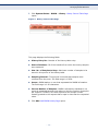
211
Figure 109: Edit Unregistered Multicast Page
212
Figure 110: IPv4 Interface Page
215
Figure 111: Add IPv4 Interface Page
216
Figure 112: IPv6 Global Configuration Page
217
Figure 113: IPv6 Interfaces Page
217
Figure 114: Add IPv6 Interface Page
218
Figure 115: IPv6 Address Page
219
Figure 116: Add IPv6 Address Page
219
Figure 117: IPv6 Default Router List Page
221
Figure 118: Add Default Router Page
222
Figure 119: IPv6 Tunnel Page
223
Figure 120: IPv6 Neighbors Page
224
Figure 121: Add IPv6 Neighbors Page
225
Figure 122: IPv6 Routes Table Page
226
Figure 123: IPv4 Static Routes
227
Figure 124: Add IPv4 Static Routes
227
Figure 125: ARP Table Page
229
Figure 126: Add ARP Page
230
Figure 127: UDP Relay Page
231
Figure 128: Add UDP Relay Page
231
Figure 129: DNS Servers Page
232
Figure 130: Add DNS Server Page
233
Figure 131: Host Mapping Page
234
Figure 132: Add Host Mapping Page
234
Figure 133: TACACS+ Page
239
Figure 134: Add TACACS+ Server Page
240
Figure 135: RADIUS Page
241
Figure 136: Add RADIUS Server Page
242
Figure 137: Management Access Authentication Page
244
Figure 138: Access Profiles Page
247
Figure 139: Caution Message
247
– 36 –
FIGURES
Figure 140: Add Access Profile Page
248
Figure 141: Profiles Rules Page
250
Figure 142: Add Profile Rule Page
250
Figure 143: Storm Control Page
252
Figure 144: Edit Storm Control Page
253
Figure 145: Port Security Page
255
Figure 146: Edit Port Security Interface Settings Page
255
Figure 147: Properties Page
260
Figure 148: Edit VLAN Authentication Page
261
Figure 149: Port Authentication Page
262
Figure 150: Edit Port Authentication Page
262
Figure 151: Host and Session Authentication Page
266
Figure 152: Edit Host and Session Authentication Page
267
Figure 153: Properties Page
268
Figure 154: VLAN Settings Page
270
Figure 155: Trusted Interfaces Page
270
Figure 156: Edit Trusted Interface Page
271
Figure 157: Binding Database Page
271
Figure 158: Add Binding Database Page
273
Figure 159: ARP Inspection Properties Page
275
Figure 160: ARP Inspection Trusted Interfaces Page
276
Figure 161: Edit Trusted Interfaces Page
276
Figure 162: ARP Inspection List Page
277
Figure 163: Add ARP List Page
277
Figure 164: ARP Inspection VLAN Settings Page
278
Figure 165: Add VLAN Settings Page
279
Figure 166: MAC-Based ACL Page
283
Figure 167: Add MAC-Based ACL Page
284
Figure 168: MAC-Based ACE Page
284
Figure 169: Add MAC-Based ACE Page
285
Figure 170: IPv4-Based ACL Page
287
Figure 171: Add IPv4-Based ACL Page
287
Figure 172: IPv4-Based ACE Page
287
Figure 173: Add IPv4-Based ACE Page
288
Figure 174: IPv6-Based ACL Page
292
Figure 175: Add IPv6-based ACL Page
292
– 37 –
FIGURES
Figure 176: IPv6-Based ACE Page
292
Figure 177: Add IPv6-Based ACE Page
293
Figure 178: ACL Binding Page
296
Figure 179: Edit ACL Binding Page
296
Figure 180: QoS Properties Page
302
Figure 181: Edit Interface CoS Configuration Page
302
Figure 182: Queue Page
304
Figure 183: CoS/802.1p to Queue Page
306
Figure 184: DSCP to Queue Page
307
Figure 185: Bandwidth Page
308
Figure 186: Edit Bandwidth Page
308
Figure 187: Global Settings Page
310
Figure 188: Edit QoS Interface Settings Page
311
Figure 189: Advanced Global Settings Page
314
Figure 190: DSCP Remarking Page
316
Figure 191: Class Mapping Page
317
Figure 192: Add Class Mapping Page
317
Figure 193: Aggregate Policer Page
319
Figure 194: Add Aggregate Policer Page
319
Figure 195: Policy Table Page
321
Figure 196: Add Policy Table Page
321
Figure 197: Policy Class Maps Page
321
Figure 198: Add Policy Class Map Page
322
Figure 199: Policy Binding Page
324
Figure 200: FIP Snooping Page
326
Figure 201: Edit FIP Snooping Interface Settings Page
326
Figure 202: FCF Mac Address Filtering Page
327
Figure 203: Add FCF MAC Address Filter Page
327
Figure 204: FIP Snooping Tunnel Setting Table Page
329
Figure 205: Add Static FIP Snooping Tunnel Page
329
Figure 206: Cut-through Page
331
Figure 207: Edit Interface Setting Page
332
Figure 208: QCN Page
334
Figure 209: Edit Quantized Congestion Notification Page
335
Figure 210: Difference Between IEEE 802.3x PAUSE and PFC Frames
336
Figure 211: PFC Page
341
– 38 –
FIGURES
Figure 212: Edit Priority-based Flow Control Page
342
Figure 213: ETS Page
342
Figure 214: DCBX Page
343
Figure 215: Edit Port Settings Page
344
Figure 216: Application to Priority Mapping Table Page
344
Figure 217: Add Application to Priority Mapping Page
345
Figure 218: Engine ID Page
351
Figure 219: SNMP Views Page
352
Figure 220: Add View Page
352
Figure 221: SNMP Users Page
354
Figure 222: Add User Page
354
Figure 223: Groups Page
356
Figure 224: Add Group Page
357
Figure 225: Communities Page
358
Figure 226: Add SNMP Community Page
359
Figure 227: Trap Settings Page
360
Figure 228: SNMPv1,2 Notification Recipient Page
361
Figure 229: Add SNMP Notification Recipient Page
362
Figure 230: SNMPv3 Notification Recipient Page
363
Figure 231: Add SNMP Notification Recipient Page
363
Figure 232: Notification Filter Page
365
Figure 233: Add Notification Filter Page
365
– 39 –
FIGURES
– 40 –
TABLES
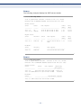
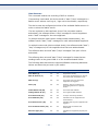
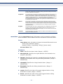
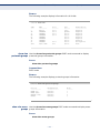
Table 1: Key Features
45
Table 2: Basic System Defaults
50
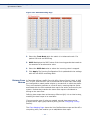
Table 3: Web Page Configuration Buttons
61
Table 4: Switch Main Menu
62
Table 5: Default Mapping Queues
305
Table 6: CLI Conventions
372
Table 7: Keyboard Keys
374
Table 8: Troubleshooting Chart
855
– 41 –
TABLES
– 42 –
SECTION I
GETTING STARTED
This section provides an overview of the switch, and introduces some basic
concepts about network switches. It also describes the basic settings
required to access the management interface.
This section includes these chapters:
◆
"Introduction" on page 45
◆
"Initial Switch Configuration" on page 51
– 43 –
SECTION I | Getting Started
– 44 –
1
INTRODUCTION
This switch provides a broad range of features for Layer 2 switching. It
includes a management agent that allows you to configure the features
listed in this manual. The default configuration can be used for most of the
features provided by this switch. However, there are many options that you
should configure to maximize the switch’s performance for your particular
network environment.
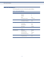
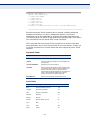
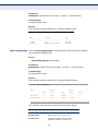
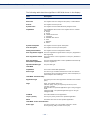
KEY FEATURES
Table 1: Key Features
Feature
Description
Configuration Backup
and Restore
Using management station or HTTP/TFTP server
Authentication
Console, Telnet, web – user name/password, RADIUS, TACACS+
Port – IEEE 802.1X, MAC-based authentication
SNMP v1/2c - Community strings
SNMP version 3 – MD5 or SHA password
Telnet – SSH
Web – HTTPS
General Security
Measures
AAA
ARP inspection
DHCP Snooping (with Option 82 relay information)
Network Access – MAC Address Authentication
Port Authentication – IEEE 802.1X
Port Security – MAC address filtering
Access Control Lists
Supports IPv4, IPv6, and MAC ACLs, 512 rules per system
DHCP
Client
DNS
Client
Port Configuration
Speed and duplex mode and flow control
Port Trunking
Supports up to 8 trunks – static or dynamic trunking (LACP)
Port Mirroring
One or more source ports to one analysis port
Congestion Control
Rate Limiting
Throttling for broadcast, multicast, unknown unicast storms
Address Table
32K MAC addresses in the forwarding table, 1K static MAC
addresses, 256 L2 multicast groups
IEEE 802.1D Bridge
Supports dynamic data switching and addresses learning
Store-and-Forward
Switching
Supported to ensure wire-speed switching while eliminating bad
frames
Spanning Tree Algorithm
Supports standard STP, Rapid Spanning Tree Protocol (RSTP), and
Multiple Spanning Trees (MSTP)
– 45 –
CHAPTER 1 | Introduction
Description of Software Features
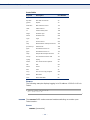
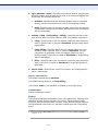
Table 1: Key Features (Continued)
Feature
Description
Virtual LANs
Up to 256 using IEEE 802.1Q, port-based, protocol-based, subnetbased VLANs
Traffic Prioritization
Default port priority, traffic class map, queue scheduling, or
Differentiated Services Code Point (DSCP)
Qualify of Service
Supports Differentiated Services (DiffServ)
Link Layer Discovery
Protocol
Used to discover basic information about neighboring devices
Multicast Filtering
Supports IGMP/MLD snooping, query, and profile filtering
Data Center Ethernet
Supports FIP Snooping, cut-through switching, QCN, PFC, ETS,
and DCBX
DESCRIPTION OF SOFTWARE FEATURES
The switch provides a wide range of advanced performance-enhancing
features. Flow control eliminates the loss of packets due to bottlenecks
caused by port saturation. Storm suppression prevents broadcast,
multicast or unknown unicast traffic storms from engulfing the network.
Port-based, protocol-based and subnet-based VLANs, plus support for
automatic GVRP VLAN registration provide traffic security and efficient use
of network bandwidth. CoS priority queueing ensures the minimum delay
for moving real-time multimedia data across the network. While multicast
filtering provides support for real-time network applications. Some of the
management features are briefly described below.
CONFIGURATION You can save the current configuration settings to a file on the
BACKUP AND management station (using the web interface) or an HTTP/TFTP server
RESTORE (using the web or console interface), and later download this file to restore
the switch configuration settings.
AUTHENTICATION This switch authenticates management access via the console port, Telnet,
or a web browser. User names and passwords can be configured locally or
can be verified via a remote authentication server (i.e., RADIUS or
TACACS+). Port-based authentication is also supported via the IEEE
802.1X protocol. This protocol uses Extensible Authentication Protocol over
LANs (EAPOL) to request user credentials from the 802.1X client, and then
verifies the client’s right to access the network via an authentication server.
Other authentication options include HTTPS for secure management access
via the web, SSH for secure management access over a Telnet-equivalent
connection, SNMP Version 3, IP address filtering for SNMP/Telnet/web
management access. MAC address filtering and IP source guard also
provide authenticated port access. While DHCP snooping is provided to
prevent malicious attacks from insecure ports
– 46 –
CHAPTER 1 | Introduction
Description of Software Features
ACCESS CONTROL ACLs provide packet filtering for IPv4 frames (based on address, protocol,
LISTS Layer 4 protocol port number or TCP control code), IPv6 frames (based on
address, next header type, or flow label), or any frames (based on MAC
address or Ethernet type). ACLs can be used to improve performance by
blocking unnecessary network traffic or to implement security controls by
restricting access to specific network resources or protocols.
PORT CONFIGURATION You can manually configure the speed, duplex mode, and flow control used
on specific ports, or use auto-negotiation to detect the connection settings
used by the attached device. Use full-duplex mode on ports whenever
possible to double the throughput of switch connections. Flow control
should also be enabled to control network traffic during periods of
congestion and prevent the loss of packets when port buffer thresholds are
exceeded. The switch supports flow control based on the IEEE 802.3x
standard (now incorporated in IEEE 802.3-2005).
RATE LIMITING This feature controls the maximum rate for traffic transmitted or received
on an interface. Rate limiting is configured on interfaces at the edge of a
network to limit traffic into or out of the network. Packets that exceed the
acceptable amount of traffic are dropped.
PORT MIRRORING The switch can unobtrusively mirror traffic from any port, VLAN or packets
with a specified MAC address to a monitor port. You can then attach a
protocol analyzer or RMON probe to this port to perform traffic analysis and
verify connection integrity.
PORT TRUNKING Ports can be combined into an aggregate connection. Trunks can be
manually set up or dynamically configured using Link Aggregation Control
Protocol (LACP – IEEE 802.3-2005). The additional ports dramatically
increase the throughput across any connection, and provide redundancy by
taking over the load if a port in the trunk should fail. The switch supports
up to 8 trunks.
STORM CONTROL Broadcast, multicast and unknown unicast storm suppression prevents
traffic from overwhelming the network.When enabled on a port, the level of
traffic passing through the port is restricted. If traffic rises above a predefined threshold, it will be throttled until the level falls back beneath the
threshold.
STATIC ADDRESSES A static address can be assigned to a specific interface on this switch.
Static addresses are bound to the assigned interface and will not be
moved. When a static address is seen on another interface, the address will
be ignored and will not be written to the address table. Static addresses
can be used to provide network security by restricting access for a known
host to a specific port.
– 47 –
CHAPTER 1 | Introduction
Description of Software Features
IP ADDRESS Access to insecure ports can be controlled using DHCP Snooping which
FILTERING filters ingress traffic based on static IP addresses and addresses stored in
the DHCP Snooping table.
IEEE 802.1D BRIDGE The switch supports IEEE 802.1D transparent bridging. The address table
facilitates data switching by learning addresses, and then filtering or
forwarding traffic based on this information. The address table supports up
to 8K addresses.
STORE-AND-FORWARD The switch copies each frame into its memory before forwarding them to
SWITCHING another port. This ensures that all frames are a standard Ethernet size and
have been verified for accuracy with the cyclic redundancy check (CRC).
This prevents bad frames from entering the network and wasting
bandwidth.
To avoid dropping frames on congested ports, the switch provides 32 Mbits
for frame buffering. This buffer can queue packets awaiting transmission
on congested networks.
SPANNING TREE The switch supports these spanning tree protocols:
ALGORITHM
◆
Spanning Tree Protocol (STP, IEEE 802.1D) – This protocol provides
loop detection. When there are multiple physical paths between
segments, this protocol will choose a single path and disable all others
to ensure that only one route exists between any two stations on the
network. This prevents the creation of network loops. However, if the
chosen path should fail for any reason, an alternate path will be
activated to maintain the connection.
◆
Rapid Spanning Tree Protocol (RSTP, IEEE 802.1D-2004) – This protocol
reduces the convergence time for network topology changes to about 3
to 5 seconds, compared to 30 seconds or more for the older IEEE
802.1D STP standard. It is intended as a complete replacement for STP,
but can still interoperate with switches running the older standard by
automatically reconfiguring ports to STP-compliant mode if they detect
STP protocol messages from attached devices.
◆
Multiple Spanning Tree Protocol (MSTP, IEEE 802.1D-2004) – This
protocol is a direct extension of RSTP. It can provide an independent
spanning tree for different VLANs. It simplifies network management,
provides for even faster convergence than RSTP by limiting the size of
each region, and prevents VLAN members from being segmented from
the rest of the group (as sometimes occurs with IEEE 802.1D STP).
– 48 –
CHAPTER 1 | Introduction
Description of Software Features
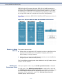
VIRTUAL LANS The switch supports up to 256 VLANs. A Virtual LAN is a collection of
network nodes that share the same collision domain regardless of their
physical location or connection point in the network. The switch supports
tagged VLANs based on the IEEE 802.1Q standard. Members of VLAN
groups can be dynamically learned via GVRP, or ports can be manually
assigned to a specific set of VLANs. This allows the switch to restrict traffic
to the VLAN groups to which a user has been assigned. By segmenting
your network into VLANs, you can:
◆
Eliminate broadcast storms which severely degrade performance in a
flat network.
◆
Simplify network management for node changes/moves by remotely
configuring VLAN membership for any port, rather than having to
manually change the network connection.
◆
Provide data security by restricting all traffic to the originating VLAN.
◆
Use protocol VLANs to restrict traffic to specified interfaces based on
protocol type. Mac-based and subnet-based VLANs are also supported.
TRAFFIC This switch prioritizes each packet based on the required level of service,
PRIORITIZATION using four priority queues with strict or Weighted Round Robin Queuing. It
uses IEEE 802.1p and 802.1Q tags to prioritize incoming traffic based on
input from the end-station application. These functions can be used to
provide independent priorities for delay-sensitive data and best-effort data.
This switch also supports several common methods of prioritizing layer 3/4
traffic to meet application requirements. Traffic can be prioritized based on
the DSCP field in the IP frame. When these services are enabled, the
priorities are mapped to a Class of Service value by the switch, and the
traffic then sent to the corresponding output queue.
QUALITY OF SERVICE Differentiated Services (DiffServ) provides policy-based management
mechanisms used for prioritizing network resources to meet the
requirements of specific traffic types on a per-hop basis. Each packet is
classified upon entry into the network based on access lists, IP Precedence
or DSCP values, or VLAN lists. Using access lists allows you select traffic
based on Layer 2, Layer 3, or Layer 4 information contained in each
packet. Based on network policies, different kinds of traffic can be marked
for different kinds of forwarding.
MULTICAST FILTERING Specific multicast traffic can be assigned to its own VLAN to ensure that it
does not interfere with normal network traffic and to guarantee real-time
delivery by setting the required priority level for the designated VLAN. The
switch uses IGMP Snooping and Query to manage multicast group
registration for IPv4 traffic.
– 49 –
CHAPTER 1 | Introduction
Basic System Defaults
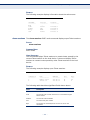
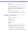
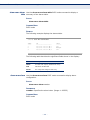
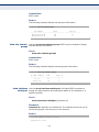
BASIC SYSTEM DEFAULTS
The following table lists some of the basic system defaults.
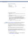
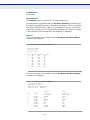
Table 2: Basic System Defaults
Function
Parameter
Default
Console Port Connection
Baud Rate
115200 bps
Data bits
8
Stop bits
1
Parity
None
Local Console Timeout
10 minutes
Privileged Exec User Name
admin
Privileged Exec Password
None
IP Address
None
Subnet Mask
None
Default Gateway
None
DHCP Client
Enabled
Default VLAN
1
PVID
1
HTTP Server
Enabled
HTTP Port Number
80
HTTP Secure Server
Disabled
HTTP Secure Server Port
443
SNMP Agent
Enabled
Community Strings
None
Authentication
IP Settings
Virtual LANs
Web Management
SNMP
– 50 –
2
INITIAL SWITCH CONFIGURATION
This chapter includes information on connecting to the switch and basic
configuration procedures.
CONNECTING TO THE SWITCH
The switch includes a built-in network management agent. The agent
offers a variety of management options, including SNMP, RMON (Groups 1,
2, 3, 9) and a web-based interface. A PC may also be connected directly to
the switch for configuration and monitoring via a command line interface
(CLI).
NOTE: An IP address for this switch is obtained via DHCP by default. To
change this address, see “Setting an IPv4 Address.”
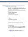
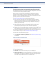
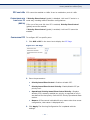
CONFIGURATION The switch’s HTTP web agent allows you to configure switch parameters,
OPTIONS monitor port connections, and display statistics using a standard web
browser such as Internet Explorer 5.x or above, Netscape 6.2 or above,
and Mozilla Firefox 2.0 or above. The switch’s web management interface
can be accessed from any computer attached to the network.
The CLI program can be accessed by a direct connection to the RS-232
serial console port on the switch, or remotely by a Telnet or Secure Shell
(SSH) connection over the network.
The switch’s management agent also supports SNMP (Simple Network
Management Protocol). This SNMP agent permits the switch to be managed
from any system in the network using network management software.
The switch’s web interface, console interface, and SNMP agent allow you to
perform management functions such as those shown below:
◆
Set user names and passwords
◆
Set an IP interface
◆
Configure SNMP parameters
◆
Enable/disable any port
◆
Set the speed/duplex mode for any port
– 51 –
CHAPTER 2 | Initial Switch Configuration
Connecting to the Switch
◆
Configure the bandwidth of any port by limiting input or output rates
◆
Control port access through IEEE 802.1X security or static address
filtering
◆
Filter packets using Access Control Lists (ACLs)
◆
Configure up to 256 IEEE 802.1Q VLANs
◆
Enable GVRP automatic VLAN registration
◆
Configure IGMP multicast filtering
◆
Upload and download system firmware or configuration files via HTTP
(using the web interface) or TFTP (using the command line or web
interface)
◆
Configure Spanning Tree parameters
◆
Configure Class of Service (CoS) priority queuing
◆
Configure static or LACP trunks (up to 8)
◆
Enable port mirroring
◆
Set storm control on any port for excessive broadcast, multicast, or
unknown unicast traffic
◆
Display system information and statistics
REQUIRED The switch provides an RS-232 serial port that enables a connection to a
CONNECTIONS PC or terminal for monitoring and configuring the switch. A null-modem
console cable is provided with the switch.
Attach a VT100-compatible terminal, or a PC running a terminal emulation
program to the switch. You can use the console cable provided with this
package, or use a null-modem cable that complies with the wiring
assignments shown in the Installation Guide.
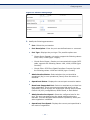
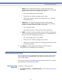
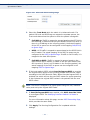
To connect a terminal to the console port, complete the following steps:
1. Connect the console cable to the serial port on a terminal, or a PC
running terminal emulation software, and tighten the captive retaining
screws on the DB-9 connector.
2. Connect the other end of the cable to the RS-232 serial port on the
switch.
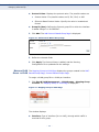
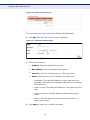
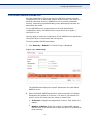
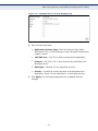
3. Make sure the terminal emulation software is set as follows:
■
Select the appropriate serial port (COM port 1 or COM port 2).
■
Set the baud rate to 115200 bps.
– 52 –
CHAPTER 2 | Initial Switch Configuration
Console Connection
■
Set the data format to 8 data bits, 1 stop bit, and no parity.
■
Set flow control to none.
■
Set the emulation mode to VT100.
■
When using HyperTerminal, select Terminal keys, not Windows
keys.
NOTE: Once you have set up the terminal correctly, the console login screen
will be displayed.
For a description of how to use the CLI, see "Using the CLI Interface" on
page 369.”
REMOTE Prior to accessing the switch’s onboard agent via a network connection,
CONNECTIONS you must first configure it with a valid IP address, subnet mask, and
default gateway using a console connection, or DHCP protocol.
The IP address for this switch is obtained via DHCP by default. To manually
configure this address or enable dynamic address assignment via DHCP,
see "Setting an IPv4 Address" on page 54.
NOTE: This switch supports four concurrent Telnet or SSH sessions.
After configuring the switch’s IP parameters, you can access the onboard
configuration program from anywhere within the attached network. The
command-line interface can be accessed using Telnet from any computer
attached to the network. The switch can also be managed by any computer
using a web browser (Internet Explorer 5.0 or above, Netscape 6.2 or
above, or Mozilla Firefox 2.0 or above), or from a network computer using
SNMP network management software.
CONSOLE CONNECTION
The CLI program provides two different command levels — normal access
level (Normal Exec) and privileged access level (Privileged Exec). The
commands available at the Normal Exec level are a limited subset of those
available at the Privileged Exec level and allow you to only display
information and use basic utilities. To fully configure the switch
parameters, you must access the CLI at the Privileged Exec level.
Access to both CLI levels are controlled by user names and passwords. The
switch has a default user name for the Privileged Exec level. To log into the
CLI at the Privileged Exec level using the default user name, perform these
steps:
– 53 –
CHAPTER 2 | Initial Switch Configuration
Setting Passwords
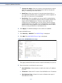
1. To initiate your console connection, press <Enter>. The “User Access
Verification” procedure starts.
2. At the User Name prompt, enter “admin.” (There is no default
password.)
3. The session is opened and the CLI displays the “Console#” prompt
indicating you have access at the Privileged Exec level.
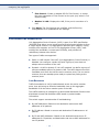
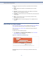
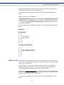
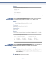
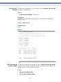
SETTING PASSWORDS
If this is your first time to log into the CLI program, you should define a
new password for the default user name using the “username” command,
record it and put it in a safe place.
Passwords can consist of up to 159 alphanumeric characters and are case
sensitive. To prevent unauthorized access to the switch, set the passwords
as follows:
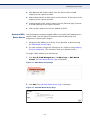
1. Open the console interface with the default user name “admin” to
access the Privileged Exec level.
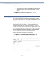
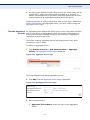
2. Type “configure” and press <Enter>.
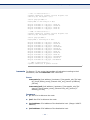
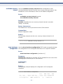
3. Type “username admin password password,” for the Privileged Exec
level, where password is your new password. Press <Enter>.
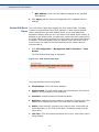
User Name:admin
Console#configure
Console(config)#username admin password [password]
Console(config)#
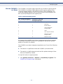
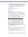
SETTING AN IPV4 ADDRESS
You must establish IP address information for the switch to obtain
management access through the network. This can be done in either of the
following ways:
◆
Manual — You have to input the information, including IP address and
subnet mask. If your management station is not in the same IP subnet
as the switch, you will also need to specify the default gateway router.
◆
Dynamic — The switch can send IP configuration requests to a DHCP
address allocation server on the network.
– 54 –
CHAPTER 2 | Initial Switch Configuration
Setting an IPv4 Address
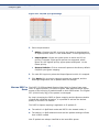
MANUAL You can manually assign an IP address to the switch. You may also need to
CONFIGURATION specify a default gateway that resides between this device and
management stations that exist on another network segment. Valid IP
addresses consist of four decimal numbers, 0 to 255, separated by periods.
Anything outside this format will not be accepted by the CLI program.
NOTE: The IP address for this switch is obtained via DHCP by default.
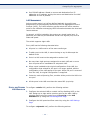
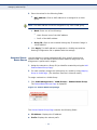
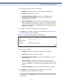
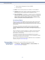
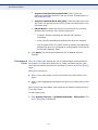
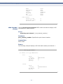
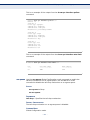
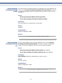
To assign an IP address to the switch, complete the following steps
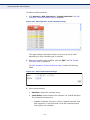
1. From the Global Configuration mode prompt, type “interface vlan 1” to
access the interface-configuration mode. Press <Enter>.
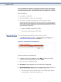
2. Type “ip address ip-address netmask,” where “ip-address” is the switch
IP address and “netmask” is the network mask for the network. Press
<Enter>.
3. Type “exit” to return to the global configuration mode prompt. Press
<Enter>.
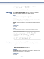
4. To set the IP address of the default gateway for the network to which
the switch belongs, type “ip default-gateway gateway,” where
“gateway” is the IP address of the default gateway. Press <Enter>.
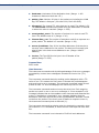
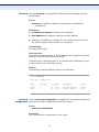
Console(config)#interface vlan 1
Console(config-if)#ip address 192.168.1.5 255.255.255.0
Console(config-if)#exit
Console(config)#ip default-gateway 192.168.1.254
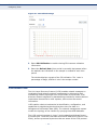
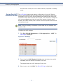
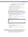
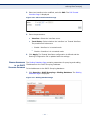
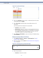
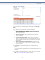
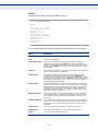
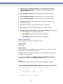
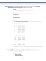
DYNAMIC Obtaining an IPv4 Address
CONFIGURATION If you select the “dhcp” option, the system will immediately start
broadcasting service requests. IP will be enabled but will not function until
a DHCP reply has been received. Requests are broadcast every few
minutes using exponential backoff until IP configuration information is
obtained from a DHCP server. DHCP values can include the IP address,
subnet mask, and default gateway. If the DHCP server is slow to respond,
you may need to use the “renew dhcp” command to re-start broadcasting
service requests.
Note that the “renew dhcp” command can be used to start broadcasting
service requests for any VLAN configured to obtain address assignments
through DHCP. It may be necessary to use this command when DHCP is
configured on a VLAN, and the member ports which were previously shut
down are now enabled.
If the “dhcp” option is saved to the startup-config file, then the switch will
start broadcasting service requests as soon as it is powered on.
– 55 –
CHAPTER 2 | Initial Switch Configuration
Setting an IPv4 Address
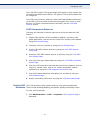
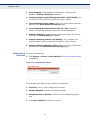
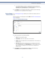
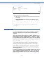
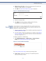
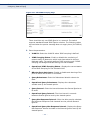
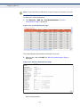
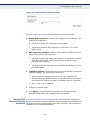
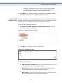
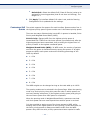
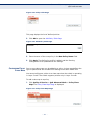
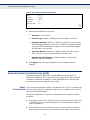
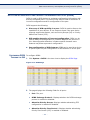
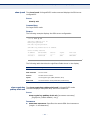
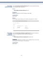
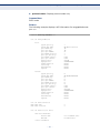
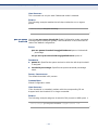
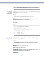
To automatically configure the switch by communicating with DHCP
address allocation servers on the network, complete the following steps:
1. From the Global Configuration mode prompt, type “interface vlan 1” to
access the interface-configuration mode. Press <Enter>.
2. At the interface-configuration mode prompt, type “ip address dhcp” and
press <Enter>.
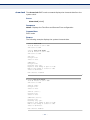
3. Type “end” to return to the Privileged Exec mode. Press <Enter>.
4. Wait a few minutes, and then check the IP configuration settings by
typing the “show ip interface” command. Press <Enter>.
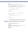
5. Then save your configuration changes by typing “copy running-config
startup-config.” Enter the startup file name and press <Enter>.
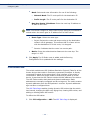
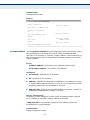
Console(config)#interface vlan 1
Console(config-if)#ip address dhcp
Console(config-if)#end
Console#copy running-config startup-config
Overwrite file [startup-config] ?[Yes/press any key for no]....01-Jan-2010
06:13:19 %COPY-I-FILECPY: Files Copy - source URL running-config
destination URL flash://startup-config
01-Jan-2010 06:13:29 %COPY-N-TRAP: The copy operation was completed
successfully
Copy succeeded
– 56 –
SECTION II
WEB CONFIGURATION
This section describes the basic switch features, along with a detailed
description of how to configure each feature via a web browser.
This section includes these chapters:
◆
"Using the Web Interface" on page 59
◆
"Monitoring System Status" on page 67
◆
"Administration" on page 87
◆
"Configuring Ports & VLANs" on page 141
◆
"Configuring the Spanning Tree Protocol" on page 169
◆
"Managing MAC Address Tables" on page 187
◆
"Configuring Multicast Forwarding" on page 191
◆
"Configuring IP Information" on page 213
◆
"Configuring Security" on page 237
◆
"Defining Access Control" on page 281
◆
"Configuring Quality of Service" on page 299
◆
"Configuring DCE" on page 325
◆
"Configuring SNMP" on page 347
– 57 –
SECTION II | Web Configuration
– 58 –
3
USING THE WEB INTERFACE
This switch provides an embedded HTTP web agent. Using a web browser
you can configure the switch and view statistics to monitor network
activity. The web agent can be accessed by any computer on the network
using a standard web browser (Internet Explorer 5.0 or above, Netscape
6.2 or above, or Mozilla Firefox 2.0.0.0 or above).
NOTE: You can also use the Command Line Interface (CLI) to manage the
switch over a serial connection to the console port or via Telnet. For more
information on using the CLI, refer to “Using the CLI Interface.”
CONNECTING TO THE WEB INTERFACE
Prior to accessing the switch from a web browser, be sure you have first
performed the following tasks:
1. Configure the switch with a valid IP address, subnet mask, and default
gateway using an out-of-band serial connection, BOOTP or DHCP
protocol. (See “Setting an IPv4 Address.”)
2. Set user names and passwords using an out-of-band serial connection.
Access to the web agent is controlled by the same user names and
passwords as the onboard configuration program. (See “Setting
Passwords.”)
3. After you enter a user name and password, you will have access to the
system configuration program.
NOTE: You are allowed three attempts to enter the correct password; on
the third failed attempt the current connection is terminated.
NOTE: If you log into the web interface as guest (Normal Exec level), you
can view the configuration settings or change the guest password. If you
log in as “admin” (Privileged Exec level), you can change the settings on
any page.
NOTE: If the path between your management station and this switch does
not pass through any device that uses the Spanning Tree Algorithm, then
you can set the switch port attached to your management station to fast
forwarding (i.e., enable Edge Port) to improve the switch’s response time
to management commands issued through the web interface. See
“Defining STP Interface Settings.”
– 59 –
CHAPTER 3 | Using the Web Interface
Navigating the Web Browser Interface
NAVIGATING THE WEB BROWSER INTERFACE
To access the web-browser interface you must first enter a user name and
password. The administrator has Read/Write access to all configuration
parameters and statistics. The default user name and password for the
administrator is “admin.”
HOME PAGE When your web browser connects with the switch’s web agent, the home
page is displayed as shown below. The home page displays the Main Menu
on the left side of the screen and System Information on the right side. The
Main Menu links are used to navigate to other menus, and display
configuration parameters and statistics.
Figure 1: Home Page
– 60 –
CHAPTER 3 | Using the Web Interface
Navigating the Web Browser Interface
CONFIGURATION Configurable parameters have a dialog box or a drop-down list. Once a
OPTIONS configuration change has been made on a page, be sure to click on the
Apply button to confirm the new setting. The following table summarizes
the web page configuration buttons.
Table 3: Web Page Configuration Buttons
Button
Action
Apply
Sets specified values to the system.
Revert
Cancels specified values and restores current
values prior to pressing “Apply.”
Help
Links directly to web help.
NOTE: To ensure proper screen refresh, be sure that Internet Explorer 5.x
is configured as follows: Under the menu “Tools / Internet Options /
General / Temporary Internet Files / Settings,” the setting for item “Check
for newer versions of stored pages” should be “Every visit to the page.”
NOTE: When using Internet Explorer 5.0, you may have to manually refresh
the screen after making configuration changes by pressing the browser’s
refresh button.
PANEL DISPLAY The web agent displays an image of the switch’s ports. The Mode can be
set to display different information for the ports, including Active (i.e., up
or down), Duplex (i.e., half or full duplex), or Flow Control (i.e., with or
without flow control).
Figure 2: Front Panel Indicators
– 61 –
CHAPTER 3 | Using the Web Interface
Navigating the Web Browser Interface
MAIN MENU Using the onboard web agent, you can define system parameters, manage
and control the switch, and all its ports, or monitor network conditions. The
following table briefly describes the selections available from this program.
Table 4: Switch Main Menu
Menu
Description
Page
System Settings
Provides basic system description, including contact information
68
Interface
Displays Ethernet interface statistics
69
Etherlike
Displays Etherlike MIB information
70
RMON
Displays RMON statistics
72
Health
Displays the switch fan status and temperature
83
Show Log
Displays system logs
83
Manages access user names and passwords
87
System Time
Configures the curent time, time zone, DST, and time source
89
SNTP Settings
Configures SNTP server settings
92
SNTP Authentication
Configures authentication keys for SNTP servers
96
Log Settings
Configures system log severity levels
98
Remote Log Servers
Configures remote Syslog server settings
99
Upgrade/Backup Firmware
Uploads or backs up operation code files
103
Active Image
Sets the operation code to boot the switch
105
Save Configuration
Backs up and restores switch configuration files
106
Copy/Save Configuration
Saves or copies the switch running configuration to a file
108
DHCP Auto Configuration
Configures automatic configuration from a DHCP server
109
Restarts the switch software
111
Optical Module Status
Displays information on installed tranceivers
112
CPU Utilization
Monitors CPU resource utilization
113
Properties
Configures LLDP general parameters
115
Port Settings
Configures LLDP settings for port interfaces
117
LLDP MED Network Policy
Configures LLDP support for media devices
119
LLDP MED Port Settings
Configures LLDP media TLVs to be advertised on ports
120
Neighbors Information
Displays LLDP information from neighboring devices
124
LLDP Statistics
Displays LLDP statistics per port
129
System Status
Administration
User Accounts
Time Settings
System Log
File Management
Reboot
Diagnostics
LLDP
– 62 –
CHAPTER 3 | Using the Web Interface
Navigating the Web Browser Interface
Table 4: Switch Main Menu (Continued)
Menu
Description
Page
LLDP Overloading
Displays LLDP TLV statistics
130
LLDP MED Port Status Details
Displays LLDP MED
132
LLDP MED Port Status
Displays LLDP global information
136
sFlow Receivers Settings
Sets sFlow receiver IP addresses
138
sFlow Interface Settings
Configures sFlow receiver port settings
139
sFlow Statistics
Displays sFlow statistics
140
Configures global and per-port interface settings
141
LAG Management
Displays LAG global and port settings
146
LAG Settings
Configures settings for specific LAGs
148
LACP
Configures Link Aggregation Control Protocol settings
149
Create VLAN
Displays and configures VLANs
153
Interface Settings
Configures VLAN parameters for interfaces
154
Port to VLAN
Displays port membership of VLANs
157
Port VLAN Membership
Displays the VLAN membership of ports
158
Port and VLAN Mirroring
Configures mirroring for ports and VLANs
159
GVRP Settings
Configures Generic VLAN Registration Protocol settings
161
MAC-Based Groups
Configures VLANs based on MAC addresses
163
Subnet-Based Groups
Configures VLANs based on IP subnets
164
Protocol-Based Groups
Configures VLANs based on traffic types
165
Mapping Groups to VLANs
Maps MAC- and protocol-based groups to VLANs
166
STP Global Settings
Configures Spanning Tree global settings
170
STP Interface Settings
Configures Spanning Tree port settings
172
RSTP Interface Settings
Configures Rapid Spanning Tree port settings
175
MSTP Properties
Configures Multiple Spanning Tree global settings
178
VLAN to MST Instance
Maps VLANs to MST instances
179
MST Instance Settings
Configures and displays settings per MST instance
181
MSTP Interface Settings
Configures port MST settings for all instances
182
Static Addresses
Displays and configures static MAC addresses
187
Dynamic Address Settings
Configures the aging time for the MAC address table
189
sFlow
Port & VLAN Management
Port Settings
Link Aggregation
VLAN Settings
VLAN Groups
Spanning Tree
MAC Address Tables
– 63 –
CHAPTER 3 | Using the Web Interface
Navigating the Web Browser Interface
Table 4: Switch Main Menu (Continued)
Menu
Description
Page
Dynamic Addresses
Displays dynamically-learned MAC addresses
189
Properties
Configures bridge multicast filtering settings
194
MAC Group Address
Displays and configures multicast VLAN or MAC-based groups
196
IP Multicast Group Address
Displays and configures IP-based multicast groups
198
IGMP Snooping
Enables IPv4 IGMP Snooping
200
MLD Snooping
Enables IPv6 MLD Snooping
203
IGMP/MLD IP Multicast Group
Displays multicast groups learned from IGMP/MLD snooping
207
Multicast Router Port
Displays and configures ports connected to multicast routers
208
Forward All
Configures ports to receive all multicast streams in a VLAN
209
Unregistered Multicast
Configures the forwarding of unknown multicast frames
211
IPv4 Interface
Configures IPv4 interfaces
214
IPv6 Global Configuration
Configures IPv6 global parameters
216
IPv6 Interfaces
Configures IPv6 interfaces
217
IPv6 Addresses
Assigns IPv6 addresses to interfaces
219
IPv6 Default Router List
Displays and configures IPv6 router addresses
220
IPv6 Tunnel
Configures ISATAP tunnel parameters
222
IPv6 Neighbors
Displays IPv6 neighbors on IPv6 interfaces
224
IPv6 Routes
Displays and configures IPv6 routes table
226
IPv4 Static Routes
Displays and configures IPv4 static routes
227
ARP
Configures Address Resolution Protocol settings
228
UDP Relay
Configures IPv4 UDP relaying
230
DNS Servers
Configures DNS servers
231
Host Mapping
Configures static mapping of DNS names to IP addresses
233
TACACS+
Configures TACACS+ authentication servers
238
RADIUS
Configures RADIUS authentication servers
241
Management Access Authentication
Defines management access authentication methods
244
Access Profiles
Configures access profiles
246
Profile Rules
Configures accress rules for profiles
249
Storm Control
Configures braodcast, multicast, unknown unicast storm control
252
Port Security
Configures MAC-based port security
254
Multicast
IP Configuration
Management and IP Interface
Domain Name System
Security
Mgmt Access Method
– 64 –
CHAPTER 3 | Using the Web Interface
Navigating the Web Browser Interface
Table 4: Switch Main Menu (Continued)
Menu
Description
Page
Properties
Configures 802.1X port access control global parameters
259
Port Authentication
Configures 802.1X parameters for ports
261
Host and Session Authentication
Configures 802.1X port mode
265
Properties
Configures DHCP Snooping general parameters
268
VLAN Settings
Enables DHCP Snooping on specified VLANs
269
Trusted Interfaces
Configures DHCP trusted interfaces
270
Binding Database
Adds static IP addresses to the DHCP Snooping database
271
Properties
Configures global Dynamic ARP Inspection parameters
274
Trusted Interfaces
Defines trusted and untrusted ARP Inspection interfaces
275
ARP Inspection List
Creates static ARP binding lists
277
VLAN Settings
Enables ARP Inspection on VLANs
278
MAC-Based ACL
Configures MAC-based access control lists
283
MAC-Based ACE
Adds rules to a MAC-based ACL
284
IPv4 Based ACL
Configures IPv4-based access control lists
286
IPv4 Based ACE
Adds rules to an IPv4-based ACL
287
IPv6 Based ACL
Configures IPv6-based access control lists
291
IPv6 Based ACE
Adds rules to an IPv6-based ACL
292
ACL Binding
Binds ACLs to interfaces
295
QoS Properties
Sets the QoS mode for the system and CoS priorities
301
Queue
Sets the queue method and WRR values
303
CoS/802.1p to Queue
Maps CoS values to egress queues
305
DSCP to Queue
Maps DSCP values to egress queues
306
Bandwidth
Limits the bandwidth of ingress interfaces
307
Defines the switch trust configuration for QoS Basic Mode
309
Global Settings
Defines the switch trust configuration for QoS Advanced Mode
313
DSCP Remarking
Changes DSCP tags for incoming traffic switched between trusted QoS
domains
315
Class Mapping
Configures class mapping to ACLs
316
Aggregate Policer
Applies QoS to one or more class maps
319
802.1X
DHCP Snooping
ARP Inspection
Access Control
Quality of Service
General
QoS Basic Mode
Global Settings
QoS Advanced Mode
– 65 –
CHAPTER 3 | Using the Web Interface
Navigating the Web Browser Interface
Table 4: Switch Main Menu (Continued)
Menu
Description
Page
Policy Table
Configures advanced QoS policies
320
Policy Class Maps
Adds class maps to policies
321
Policy Binding
Binds policy profiles to interfaces
323
FIP Snooping
Configures FCoE Initialization Protocol settings
325
Cut-through
Configures cut-through forwarding on the switch
330
QCN
Configures Quantized Congestion Notification settings
332
PFC
Configures Priority-based Flow Control settings
335
ETS
Configures Enhanced Transmission Selection settings
342
DCBX
Configures Data Center Bridging Exchange protocol settings
343
Engine ID
Defines the SNMPv3 Engine ID
350
Views
Configures SNMPv3 views
351
Users
Configures SNMPv3 users
353
Groups
Configures SNMPv3 user groups
356
Communities
Configures SNMPv1/2 communities
358
Trap Settings
Configures SNMP trap recipients
360
Notification Recipient SNMPv1,2
Configures recipients of SNMPv1/2 traps/notifications
361
Notification Recipient SNMPv3
Configures recipients of SNMPv3 notifications
363
Notification Filter
Configures SNMP notification filters
365
DCE
SNMP
– 66 –
4
MONITORING SYSTEM STATUS
This chapter describes how to view system information and configure
various options on the switch.
It includes the following topics:
◆
Displaying the System Settings
◆
Viewing Ethernet Interface
◆
Viewing Etherlike Statistics
◆
Managing RMON Statistics
◆
Monitoring the Health
◆
Viewing Memory Logs
– 67 –
CHAPTER 4 | Monitoring System Status
Displaying the System Settings
DISPLAYING THE SYSTEM SETTINGS
The System Settings Page displays system information.
To view system information:
◆
Click System Status > System Settings. The System Settings Page
is displayed.
Figure 3: System Settings Page
The System Settings page displays the following information.
◆
System Description—A description of the system.
◆
Firmware Version (Active Image)—Firmware version number of the
active image.
◆
Firmware MD5 Checksum (Active Image)—MD5 checksum of the
active image.
◆
Boot Version—Boot version number.
◆
System Uptime—Time that has elapsed since the last reboot.
◆
System Location—Physical location of the switch. Click Edit to go the
System Settings Page to enter this value.
◆
System Contact—Name of a contact person. Click Edit to go the
System Settings Page to enter this value.
◆
Host Name—Name of the switch. Click Edit to go the System Settings
Page to enter this value. By default, the switch hostname is composed
of the word switch concatenated with the three least significant bytes of
the switch MAC address (the six furthest right hexadecimal digits).
– 68 –
CHAPTER 4 | Monitoring System Status
Viewing Ethernet Interface
VIEWING ETHERNET INTERFACE
The Interface Page displays traffic statistics per port. The refresh rate of
the information can be selected.
This page is useful for analyzing the amount of traffic that is both sent and
received and its dispersion (Unicast, Multicast, and Broadcast).
To display Ethernet statistics:
1. Click System Status > Interface. The Interface Page opens.
Figure 4: Interface Page
2. Enter the parameters.
◆
Interface—Select the type of interface and specific interface for which
Ethernet statistics are to be displayed.
◆
Refresh Rate—Select the time period that passes before the interface
Ethernet statistics are refreshed. The available options are:
■
No Refresh—Statistics are not refreshed.
■
15 Sec—Statistics are refreshed every 15 seconds.
■
30 Sec—Statistics are refreshed every 30 seconds.
■
60 Sec—Statistics are refreshed every 60 seconds.
The Receive Statistics area displays information about incoming packets.
◆
Total Bytes (Octets)—Octets received, including bad packets and FCS
octets, but excluding framing bits.
◆
Unicast Packets—Good Unicast packets received.
– 69 –
CHAPTER 4 | Monitoring System Status
Viewing Etherlike Statistics
◆
Multicast Packets—Good Multicast packets received.
◆
Broadcast Packets—Good Broadcast packets received.
◆
Packets with Errors—Packets with errors received.
The Transmit Statistics area displays information about outgoing
packets.
◆
Total Bytes (Octets)—Octets transmitted, including bad packets and
FCS octets, but excluding framing bits.
◆
Unicast Packets—Good Unicast packets transmitted.
◆
Multicast Packets—Good Multicast packets transmitted.
◆
Broadcast Packets—Good Broadcast packets transmitted.
TO CLEAR STATISTICS COUNTERS:
◆
Click Clear Interface Counters to clear counters for the interface
displayed.
◆
Click Clear All Interface Counters to clear counters for all interfaces.
VIEWING ETHERLIKE STATISTICS
The Etherlike Page displays statistics per port according to the Etherlike
MIB standard definition. The refresh rate of the information can be
selected. This page provides more detailed information regarding errors in
the physical layer (Layer 1), which might disrupt traffic.
To view Etherlike Statistics:
1. Click System Status > Etherlike. The Etherlike Page opens.
– 70 –
CHAPTER 4 | Monitoring System Status
Viewing Etherlike Statistics
Figure 5: Etherlike Page
2. Enter the parameters.
◆
Interface—Select the type of interface and specific interface for which
Ethernet statistics are to be displayed.
◆
Refresh Rate—Select the amount of time that passes before the
Etherlike statistics are refreshed.
The fields are displayed for the selected interface.
◆
Frame Check Sequence (FCS) Errors—Received frames that failed
the CRC (cyclic redundancy checks).
◆
Single Collision Frames—Number of frames involved in a single
collision, but were successfully transmitted.
◆
Late Collisions—Collisions that have been detected after the first
512 bits of data.
◆
Excessive Collisions—Number of transmissions due to excessive
collisions.
◆
Oversize Packets—Packets greater than 1518 octets received.
◆
Internal MAC Receive Errors—Frames rejected because of receiver
errors.
◆
Received Pause Frames—Received flow control pause frames.
◆
Transmitted Pause Frames—Flow control pause frames transmitted
from the selected interface.
– 71 –
CHAPTER 4 | Monitoring System Status
Managing RMON Statistics
TO CLEAR STATISTICS COUNTERS:
◆
Click Clear Interface Counters to clear the selected interface’s
Etherlike statistics counters.
◆
Click Clear All Interface Counters to clear the Etherlike statistics
counters of all interfaces.
MANAGING RMON STATISTICS
RMON (Remote Networking Monitoring) enables an SNMP agent in the
switch to proactively monitor traffic statistics over a given period and send
traps to an SNMP manager. The local SNMP agent compares actual, realtime counters against predefined thresholds and generates alarms, without
the need for polling by a central SNMP management platform. This is an
effective mechanism for proactive management, provided that you have
right thresholds set relative to your network’s base line.
RMON decreases the traffic between the manager and the switch because
the SNMP manager does not have to frequently poll the switch for
information, and enables the manager to get timely status reports because
the switch reports events as they occur.
With this feature, you can perform the following actions:
◆
View statistics (counter values) as they are currently, meaning since
the last time they were cleared. You can also collect the values of these
counters over a period of time, and then view the table of collected
data, where each collected set is a single line of the History tab.
◆
Define interesting changes in counter values, such as “reached a
certain number of late collisions” (defines the alarm), and then define
what action to perform when this event occurs (log, trap, or log and
trap).
VIEWING RMON The Statistics Page displays detailed information regarding packet sizes
STATISTICS and some information regarding physical layer errors. The information
shown is according to the RMON standard. An oversized packet is defined
as an Ethernet frame with the following criteria:
◆
Packet length is greater than MRU byte size
◆
Collision event has not been detected
◆
Late collision event has not been detected
◆
Rx error event has not been detected
◆
Packet has a valid CRC
To view the RMON statistics:
– 72 –
CHAPTER 4 | Monitoring System Status
Managing RMON Statistics
1. Click System Status > RMON > Statistics.The Statistics Page opens.
Figure 6: Statistics Page
2. Select the Interface for which Ethernet statistics are to be displayed.
3. Select the Refresh Rate, the time period that passes before the
interface statistics are refreshed.
The followingstatistics are displayed for the selected interface.:
◆
Bytes Received—Number of octets received, including bad packets
and FCS octets, but excluding framing bits.
◆
Drop Events—Number of packets that were dropped.
◆
Packets Received—Number of packets received, including bad
packets, Multicast, and Broadcast packets.
◆
Broadcast Packets Received—Number of good Broadcast packets
received. This number does not include Multicast packets.
◆
Multicast Packets Received—Number of good Multicast packets
received.
◆
CRC & Align Errors—Number of CRC and Align errors that have
occurred.
◆
Undersize Packets—Number of undersized packets (less than 64
octets) received.
◆
Oversize Packets—Number of oversized packets (over 1518 octets)
received.
◆
Fragments—Number of fragments (packets with less than 64 octets,
excluding framing bits, but including FCS octets) received.
– 73 –
CHAPTER 4 | Monitoring System Status
Managing RMON Statistics
◆
Jabbers—Total number of received packets that were longer than 1632
octets. This number excludes frame bits, but includes FCS octets that
had either a bad FCS (Frame Check Sequence) with an integral number
of octets (FCS Error) or a bad FCS with a non-integral octet (Alignment
Error) number. A Jabber packet is defined as an Ethernet frame that
satisfies the following criteria:
■
Packet data length is greater than MRU
■
Packet has an invalid CRC
■
Rx Error Event has not been detected
◆
Collisions—Number of collisions received. If Jumbo Frames are
enabled, the threshold of Jabber Frames is raised to the maximum size
of Jumbo Frames.
◆
Frames of 64 Bytes—Number of frames, containing 64 bytes that
were received.
◆
Frames of 65 to 127 Bytes—Number of frames, containing 65-127
bytes that were received.
◆
Frames of 128 to 255 Bytes—Number of frames, containing 128-255
bytes that were received.
◆
Frames of 256 to 511 Bytes—Number of frames, containing 256-511
bytes that were received.
◆
Frames of 512 to 1023 Bytes—Number of frames, containing 5121023 bytes that were received.
◆
Frames greater than 1024 Bytes—Number of frames, containing
1024-1518 bytes, and Jumbo Frames, that were received.
TO CLEAR STATISTICS COUNTERS:
◆
Click Clear Interface Counters to clear the selected interface’s RMON
statistics counters.
◆
Click Clear All Interface Counters to clear the RMON statistics
counters of all interfaces.
CONFIGURING RMON The History Control Table Page provides the ability to collect a log of
HISTORY statistics on a port.
You can configure the sampling frequency, amount of samples to store and
the port from where to gather the data. After the data is sampled and
stored, it is displayed in the History Table Page that can be viewed by
clicking History Table.
To define RMON samples:
– 74 –
CHAPTER 4 | Monitoring System Status
Managing RMON Statistics
1. Click System Status > RMON > History. History Control Table Page
opens.
Figure 7: History Control Table Page
This page displays the following fields:
◆
History Entry No.—Number of the history table entry.
◆
Source Interface—ID of the interface from which the history samples
were captured.
◆
Max. No. of Samples to Keep—Maximum number of samples to be
stored in this portion of the History table.
◆
Sampling Interval—Time period in seconds that samples were
collected from the ports. The field range is 1-3600.
◆
Owner—RMON station or user that requested the RMON information.
The field range is 0-20 characters.
◆
Current Number of Samples—RMON is allowed by standard to not
grant all requested samples, but rather to limit the number of samples
per request. Therefore, this field represents the sample number
actually granted to the request that is equal or less than the requested
value.
2. Click Add. Add RMON History Page opens.
– 75 –
CHAPTER 4 | Monitoring System Status
Managing RMON Statistics
Figure 8: Add RMON History Page
3. Enter the parameters.
◆
New History Entry—Displays the number of the new table entry.
◆
Source Interface—Select the port/LAG from where the history
samples are to be taken.
◆
Max No. of Samples to Keep—Enter the number of samples to store.
◆
Sampling Interval—Enter the time in seconds that samples were
collected from the ports. The field range is 1-3600.
◆
Owner—Enter the RMON station or user that requested the RMON
information.
4. Click Apply. The entry is added to History Control Table Page, and the
Running Configuration file is updated.
VIEWING THE RMON The History Table Page displays interface specific statistical network
HISTORY TABLE samplings. Each table entry represents all counter values compiled during
a single sample.
To view RMON history:
1. Click System Status > RMON > History. The History Table Page
opens.
2. Click History Table. History Table Page opens.
– 76 –
CHAPTER 4 | Monitoring System Status
Managing RMON Statistics
Figure 9: History Table Page
3. From the History Entry No. list, select the entry number to display the
samples associated with that history entry.
The fields are displayed for the selected sample.
◆
Owner—History table entry owner.
◆
Sample No.—Statistics were taken from this sample.
◆
Drop Events—Dropped packets due to lack of network resources
during the sampling interval. This may not represent the exact number
of dropped packets, but rather the number of times dropped packets
were detected.
◆
Bytes Received—Octets received that including bad packets and FCS
octets, but excluding framing bits.
◆
Packets Received—Packets received, including bad packets,
Multicast, and Broadcast packets.
◆
Broadcast Packets—Good Broadcast packets received. This number
does not include Multicast packets.
◆
Multicast Packets—Good Multicast packets received.
◆
CRC Align Errors—CRC and Align errors that have occurred.
◆
Undersize Packets—Undersized packets (less than 64 octets)
received.
◆
Oversize Packets—Oversized packets (over 1518 octets) received.
◆
Fragments—Fragments (packets with less than 64 octets) received,
excluding framing bits, but including FCS octets).
◆
Jabbers—Total number of received packets that were longer than 1632
octets. This number excludes frame bits, but includes FCS octets that
– 77 –
CHAPTER 4 | Monitoring System Status
Managing RMON Statistics
had either a bad FCS (Frame Check Sequence) with an integral number
of octets (FCS Error) or a bad FCS with a non-integral octet (Alignment
Error) number.
◆
Collisions—Collisions received.
◆
Utilization—Percentage of current interface traffic compared to
maximum traffic that the interface can handle.
DEFINING RMON The Events Page provides the ability to configure events that are actions
EVENTS CONTROL performed when an alarm is generated (alarms are defined in the Alarms
Page). An event can be any combination of logs/traps.
If the action is includes logging then the events are logged in the Event Log
Table Page.
To view RMON events:
1. Click System Status > RMON > Events. The Events Page opens.
Figure 10: Events Page
This page displays previously-defined events.
2. Click Add. The Add RMON Events Page opens.
– 78 –
CHAPTER 4 | Monitoring System Status
Managing RMON Statistics
Figure 11: Add RMON Events Page
3. Enter the parameters.
◆
Event Entry—Displays the event entry index number for the new
entry.
◆
Community—Enter the SNMP community string to be included when
traps are sent (optional).
◆
Description—Enter a name for the event. This name is used in the Add
RMON Alarm Page to attach an alarm to an event.
◆
Notification Type—Select the type of action that results from this
event. Values are:
■
None—No action occurs when the alarm goes off.
■
Log (Event Log Table)—Add a log entry to the Event Log table when
the alarm goes off.
■
■
◆
Trap (SNMP Manager and Syslog Server)—Send a trap to the
remote log server when the alarm goes off.
Log and Trap—Add a log entry to the Event Log table and send a
trap to the remote log server when the alarm goes off.
Owner—Enter the device or user that defined the event.
4. Click Apply. The RMON event is added and the Running Configuration
file is updated.
– 79 –
CHAPTER 4 | Monitoring System Status
Managing RMON Statistics
VIEWING THE RMON The Event Log Table Page displays the log of events (actions) that
EVENTS LOGS occurred. An event can be logged when the type of the event is Log or Log
and Trap. The action in the event is performed when the event is bound to
an alarm (see the Alarms Page) and the conditions of the alarm have
occurred.
1. Click System Status > RMON > Events. The Events Page opens.
2. Click Event Log Table. The Event Log Table Page opens.
Figure 12: Event Log Table Page
This page displays the following fields:
◆
Event—Events log entry number.
◆
Log No.—Log number.
◆
Log Time—Time that the log entry was entered.
◆
Description—Log entry description.
DEFINING RMON RMON alarms provide a mechanism for setting thresholds and sampling
ALARMS intervals to generate exception events on any counter or any other SNMP
object counter maintained by the agent. Both the rising and falling
thresholds must be configured in the alarm. After a rising threshold is
crossed, another rising event is not generated until the companion falling
threshold is crossed. After a falling alarm is issued, the next alarm is issued
when a rising threshold is crossed.
RMON alarms provide a mechanism for setting thresholds and sampling
intervals. Exception events can be generated on remote log servers
maintained by the agent. Both the rising and falling thresholds must be
configured in the alarm. After a rising threshold is crossed, another rising
event is not generated until the companion falling threshold is crossed.
After a falling alarm is issued, the next alarm is issued when the rising
threshold is crossed.
– 80 –
CHAPTER 4 | Monitoring System Status
Managing RMON Statistics
One or more alarms are bound to an event. The event indicates the action
to be taken when the alarm occurs.
The Alarms Page provides the ability to configure alarms and to bind them
with events. Alarm counters can be monitored by either absolute values or
changes (delta) in the counter values.
To enter RMON alarms (if at least one RMON event has been defined):
1. Click System Status > RMON > Alarms. The Alarms Page opens.
Figure 13: Alarms Page
2. Click Add. The Add RMON Alarm Page opens.
Figure 14: Add RMON Alarm Page
3. Enter the parameters.
◆
Alarm Entry—Displays the alarm entry number.
– 81 –
CHAPTER 4 | Monitoring System Status
Managing RMON Statistics
◆
Interface—Select the port/LAG for which RMON statistics are
displayed.
◆
Counter Name—Select the MIB variable that indicates the type of
occurrence measured.
◆
Sample Type—Select the sampling method to generate an alarm. The
options are:
■
■
Delta—Subtracts the last sampled value from the current value. The
difference in the values is compared to the threshold. If the
threshold was passed, an alarm is generated.
Absolute—If the threshold is passed, an alarm is generated.
◆
Rising Threshold—Enter the rising counter value that triggers the
rising threshold alarm.
◆
Rising Event—Select an event, from those that you defined in the
Events table, to be performed when a rising event is triggered. Events
are created in the Events page.
◆
Falling Threshold—Enter the falling counter value that triggers the
falling threshold alarm.
◆
Falling Event—Selects an event, from those defined in the Events
table, to be performed when a falling event is triggered.
◆
Startup Alarm—Select the first event from which to start generation
of alarms. Rising is defined by crossing the threshold from a low-value
threshold to a higher-value threshold.
■
Rising Alarm—A rising counter value triggers the rising threshold
alarm.
■
Falling Alarm—A falling counter value triggers the falling threshold
alarm.
■
Rising and Falling—Both a rising and falling counter values trigger
the alarm.
◆
Interval—Enter the alarm interval time in seconds.
◆
Owner—Enter the name of the user or network management system
that receives the alarm.
4. Click Apply. The RMON alarm is added and the Running Configuration
file is updated.
– 82 –
CHAPTER 4 | Monitoring System Status
Monitoring the Health
MONITORING THE HEALTH
The Health Page displays the switch fan status and temperature.
To view the switch health parameters:
◆
Click System Status > Health. The Health Page opens.
Figure 15: Health Page
The Health page displays the following fields:
◆
Fan Status—Fan status.
◆
Temperature—Switch temperature.
◆
Main Power Supply—Status of main power supply.
◆
Redundant Power Supply Status—Status of redundant power
supply.
VIEWING MEMORY LOGS
The switch can write to the following logs:
◆
Log in RAM (cleared during reboot).
◆
Log in Flash memory (cleared only upon user command).
You can configure the messages that are written to each log by severity,
and a message can go to more than one log, including logs that reside on
external SYSLOG servers.
– 83 –
CHAPTER 4 | Monitoring System Status
Viewing Memory Logs
RAM MEMORY The RAM Memory Page displays all messages, in chronological order, that
were saved in RAM (cache).
To view log entries:
1. Click System Status > Show Log > RAM Memory. The RAM Memory
Page opens.
Figure 16: RAM Memory Page
This page displays the following fields:
◆
Log Index—Log entry number.
◆
Log Time—Time when message was generated.
◆
Severity—Event severity.
◆
Description—Message text describing the event.
2. To clear the log messages, click Clear Logs. The messages are cleared.
FLASH MEMORY The Flash Memory Page displays the messages that were stored in Flash
memory, in chronological order. Flash logs remain when the switch is
rebooted. You can clear the logs manually.
To view the Flash logs:
1. Click System Status > View Log > Flash Memory. The Flash
Memory Page opens.
– 84 –
CHAPTER 4 | Monitoring System Status
Viewing Memory Logs
Figure 17: Flash Memory Page
This page displays the following fields:
◆
Log Index—Log entry number.
◆
Log Time—Time when message was generated.
◆
Severity—Event severity.
◆
Description—Message text describing the event.
2. To clear the messages, click Clear Logs. The messages are cleared.
– 85 –
CHAPTER 4 | Monitoring System Status
Viewing Memory Logs
– 86 –
5
ADMINISTRATION
This chapter contains the following topics:
◆
Defining Users
◆
Managing the Time Settings
◆
Managing System Logs
◆
Managing System Files
◆
Rebooting the Switch
◆
Managing Device Diagnostics
◆
Configuring LLDP
◆
Configuring sFlow
DEFINING USERS
A user, in this context, is a system administrator or superuser, who
manages the switch.
The default username is admin and the default password is empty.
The User Accounts Page enables entering additional users that are
permitted to manage the switch or changing the passwords of existing
users.
NOTE: It is not permitted to delete all users. If all users are selected, the
Delete button is disabled.
To add a new user:
1. Click Administration > User Accounts. The User Accounts Page
displays.
– 87 –
CHAPTER 5 | Administration
Defining Users
Figure 18: User Accounts Page
This page displays the users defined in the system.
2. Click Add to add a new user or click Edit to modify a user. The Add/Edit
User Account Page displays.
Figure 19: Add/Edit User Account Page
3. Enter the parameters.
◆
User Name—Enter a new username between 0 and 20 characters.
UTF-8 characters are not permitted.
◆
Access Level—Select an access level.
◆
Password—Enter a password (UTF-8 characters are not permitted).
◆
Confirm Password—Enter the password again.
4. Click Apply. The user is added, and the Running Configuration file is
updated with the settings..
– 88 –
CHAPTER 5 | Administration
Managing the Time Settings
MANAGING THE TIME SETTINGS
Network time synchronization is critical because every aspect of managing,
securing, planning, and debugging a network involves determining when
events occur. Time also provides the only frame of reference between all
devices on the network. Without synchronized time, accurately correlating
log files between these devices is difficult, even impossible.
A few of the specific reasons include, tracking security breaches, network
usage. Problems affecting a large number of components can be nearly
impossible to track if timestamps in logs are inaccurate.
Time also reduces confusion in shared file systems, as it is important for
the modification times to be consistent, regardless of the machine on which
the filesystems reside.
For these reasons, it is important that the time configured on the all
devices on the network be accurate.
NOTE: The switch supports Simple Network Time Protocol (SNTP) and when
enabled, the switch dynamically synchronizes the switch time with the
SNTP server time. The switch operates only as an SNTP client, and cannot
provide time services to other devices.
This section describes the options for configuring system time, time zone,
and Daylight Savings Time (DST). It includes the following topics:
◆
System Time Options
◆
Configuring System Time
◆
Adding an SNTP Server
◆
Defining SNTP Authentication
SYSTEM TIME OPTIONS System time can be set manually by the user or dynamically by using an
SNTP server. If an SNTP server is chosen, the manual time settings are
overwritten when communications with the server is established.
As part of the boot process, the switch always configures the time, timezone, and DST in some way, either from DHCP, from SNTP, from values set
manually, or if all else fails from the factory defaults.
TIME
The following methods are available for obtaining or setting the time on the
switch:
◆
SNTP that ensures accurate network time synchronization of the switch
up to the millisecond by using an SNTP server for the clock source.
– 89 –
CHAPTER 5 | Administration
Managing the Time Settings
NOTE: Without synchronized time, accurately correlating log files between
devices is difficult, even impossible. We recommend that you use SNTP for
the clock source.
◆
Manual entry of the system time by the user.
◆
Entry of the time by the computer that accesses the switch through the
device configuration utility. If this feature is enabled, the switch uses
the system time from the configuring computer, unless the time has
been configured on the switch manually by the user or SNTP server
support is not available or enabled.
NOTE: Receiving the time from the computer configuring the switch should
be the last resort, such as after a power outage and no other time source is
available.
TIME ZONE AND DAYLIGHT SAVINGS TIME (DST)
The Time Zone and DST can be set on the switch in the following ways:
◆
Dynamic configuration of the switch through a DHCP server, where:
■
■
■
◆
Dynamic DST, when enabled and available, always takes
precedence over the manual configuration of DST.
If the server supplying the source parameters fails or dynamic
configuration is disabled by the user, the manual settings are used.
Dynamic configuration of the time zone and DST continues after the
IP address lease time has expired.
Manual configuration of the time zone and DST by the user, where the
time zone and DST set manually becomes the Operational time zone
and DST, only if the dynamic configuration of the time zone and DST is
disabled or fails.
CONFIGURING SYSTEM Use the System Time Page to configure the current time, time zone, DST,
TIME and the time source. If the time is determined manually, enter the manual
time here.
The switch does not have an internal clock that updates this value. If the
system time is set manually and the switch is rebooted, the manual time
settings must be reentered.
To define system time:
1. Click Administration> Time Settings > System Time. The System
Time Page is displayed.
– 90 –
CHAPTER 5 | Administration
Managing the Time Settings
Figure 20: System Time Page
2. Enter the parameters.
◆
Clock Source—Select the source used to set the system clock.
■
■
◆
Use Local Settings—The system time is either entered manually
or taken from the configuring computer. If this radio button is
selected, enter the Local Settings.
Use SNTP Server—The system time is obtained from an SNTP
server. Also, add an SNTP server and enable SNTP broadcast mode
by using the SNTP Settings Page. Enforce authentication of the
SNTP sessions by using the SNTP Authentication Page.
Local Settings—The local time is used when there is no alternate
source of time, such as an SNTP server:
■
Date—Enter the system date.
■
Local Time—Enter the system time.
■
Time Zone Offset—Select the difference in hours between
Greenwich Mean Time (GMT) and the local time. For example, the
Time Zone Offset for Paris is GMT +1, while the Time Zone Offset
for New York is GMT – 5.
■
Daylight Savings—Select Daylight Savings to enable DST.
■
Time Set Offset—Enter the number of minutes that Daylight
Savings Time causes clocks to adjust.
■
Daylight Savings Type—Select how DST is defined:
●
USA—According to the dates used in the USA
– 91 –
CHAPTER 5 | Administration
Managing the Time Settings
●
●
■
By Dates—Manually, typically for a country other than the USA
or a European country. Enter the following parameters:
●
From—Day and time that DST starts.
●
To—Day and time that DST ends.
●
■
European—According to the dates used by the European Union
and other countries that use this standard.
Recurring—DST occurs on the same date every year. Enter the
following parameters:
From—Date when DST begins each year.
●
Day—Day of the week on which DST begins every year.
●
Week—Week within the month from which DST begins every
year.
●
Month—Month of the year in which DST begins every year.
●
Time—The time at which DST begins every year.
To—Date when DST ends each year. For example, DST ends locally
every fourth Friday in October at 5:00 am. The parameters are:
●
Day—Day of the week on which DST ends every year.
●
Week—Week within the month from which DST ends every
year.
●
Month—Month of the year in which DST ends every year.
●
Time—The time at which DST ends every year.
3. Click Apply. The system time values are defined, and the Running
Configuration file is updated with the settings..
The time settings are displayed in the Actual Time Details block.
ADDING AN SNTP A switch can be configured to synchronize its system clock with an SNTP
SERVER server by using the SNTP Settings Page.
NOTE: If specifying an SNTP server by name, this feature requires that the
DNS servers be configured on the switch (see "Defining DNS Servers" on
page 231) to work properly.
The switch supports the following modes:
– 92 –
CHAPTER 5 | Administration
Managing the Time Settings
◆
Broadcast—The SNTP server broadcasts the time, and the switch listens
to these broadcasts. When the switch is in this mode, there is no need
to define a Unicast SNTP server.
◆
Unicast SNTP Server Mode—The switch sends Unicast queries to the list
of manually-configured SNTP servers, and waits for a response.
The switch supports having both modes active at the same time, choosing
the best source of the parameters according to the closest stratum
(distance from the reference clock).
To add an SNTP server:
1. Click Administration > Time Settings > SNTP Settings. The SNTP
Settings Page is displayed.
Figure 21: SNTP Settings Page
2. (Optional) Enable SNTP Broadcast Reception to listen to SNTP
Broadcast synchronization packets for system time information. If this
option is selected, the system does not display the SNTP server from
which the time parameters are received.
This page displays the following information for each Unicast SNTP
server:
◆
SNTP Server—SNTP server IP address. Up to eight SNTP servers can
be defined. The preferred server, or hostname, is chosen according to
its stratum level.
◆
Poll Interval—Interval (in seconds) at which the SNTP server is polled
for system time information. The poll interval is 1024 seconds.
◆
Authentication Key ID—Key Identification used to communicate
between the SNTP server and switch.
◆
Preference—Priority of use for the SNTP server.
– 93 –
CHAPTER 5 | Administration
Managing the Time Settings
■
■
■
◆
Primary—Server with the lowest stratum level. Stratum level is the
distance from the reference clock. Time information is taken from
this server.
Secondary—Server with the next lowest stratum level after the
primary server. Serves as a backup to the primary server.
In progress—SNTP server that is currently sending or receiving
SNTP information.
Status—SNTP server status. The possible options are:
■
Up—SNTP server is currently operating normally.
■
Down—SNTP server is currently not available.
■
Unknown—SNTP server is currently being searched for by the
switch.
◆
Last Response—Date and time of the last time a response was
received from this SNTP server.
◆
Offset—The estimated offset of the server's clock relative to the local
clock, in milliseconds. The host determines the value of this offset using
the algorithm described in RFC 2030.
◆
Delay—The estimated round-trip delay of the server's clock relative to
the local clock over the network path between them, in milliseconds.
The host determines the value of this delay using the algorithm
described in RFC 2030.
3. Click Add to display the Add SNTP Server Page.
Figure 22: Add SNTP Server Page
4. Enter the following parameters:
– 94 –
CHAPTER 5 | Administration
Managing the Time Settings
◆
Server Definition—Select if the SNTP server is going to be identified
by its IP address or if you are going to chose a well-known SNTP server
by name from the list.
NOTE: To specify a well-known SNTP server, the switch must be connected
to the Internet and configured with a DNS server or configured so that a
DNS server is identified by using DHCP. (See "Defining DNS Servers" on
page 231.)
◆
IP Version—Select the version of the IP address: Version 6 or
Version 4.
◆
IPv6 Address Type—Select the IPv6 address type (if IPv6 is used).
The options are
■
■
Link Local—The IPv6 address uniquely identifies hosts on a single
network link. A link local address has a prefix of FE80, is not
routable, and can be used for communication only on the local
network. Only one link local address is supported. If a link local
address exists on the interface, this entry replaces the address in
the configuration.
Global—The IPv6 address is a global Unicast IPV6 type that is visible
and reachable from other networks.
◆
Link Local Interface—Select the link local interface (if IPv6 Address
Type Link Local is selected) from the list.
◆
SNTP Server IP Address—Enter the SNTP server IP address. The
format depends on which address type was selected.
◆
SNTP Server—Select the name of the SNTP server from a list of wellknown SNTP servers. If other is chosen, enter the hostname of SNTP
server in the adjacent field.
◆
Poll Interval—Select to enable polling of the SNTP server for system
time information. All SNTP servers that are registered for polling are
polled, and the clock is selected from the server with the lowest
stratum level (distance from the reference clock.) that is reachable. The
server with the lowest stratum is considered to be the primary server.
The server with the next lowest stratum is a secondary server, and so
forth. If the primary server is down, the switch polls all servers with the
polling setting enabled, and selects a new primary server with the
lowest stratum.
◆
Authentication—Select the check box to enable authentication.
◆
Authentication Key ID—If authentication is enabled, select the value
of the key ID. (Create the authentication keys using the SNTP
Authentication Page.)
5. Click Apply. The SNTP server is added, and the Running Configuration
file is updated with the settings.
– 95 –
CHAPTER 5 | Administration
Managing the Time Settings
DEFINING SNTP The SNTP Authentication Page enables configuration of the authentication
AUTHENTICATION keys that are used when communicating with an SNTP server that requires
authentication.
After a key has been created, it must be bound to one or more relevant
SNTP servers to be authenticated. This authentication key can also be used
for authentication when receiving Broadcast synchronization.
SNTP sessions might require authentication. A Unicast SNTP server that
requires authentication must be bounded with an authentication key when
it is added by using the Add SNTP Server Page.
To define SNTP authentication:
1. Click Administration > Time Settings > SNTP Authentication. The
SNTP Authentication Page is displayed.
Figure 23: SNTP Authentication Page
2. Enable SNTP Authentication to require authentication of an SNTP
session between the switch and an SNTP server.
3. Click Apply to update the switch.
4. Click Add. The Add SNTP Authentication Page is displayed.
– 96 –
CHAPTER 5 | Administration
Managing System Logs
Figure 24: Add SNTP Authentication Page
5. Enter the following parameters:
◆
Authentication Key ID—Enter the number used to identify this SNTP
authentication key internally.
◆
Authentication Key—Enter the key used for authentication (up to
eight characters). The SNTP server must send this key for the switch to
synchronize to it.
◆
Trusted Key—Select the check box to allow the switch to receive
broadcast synchronization information only from a SNTP server by
using this authentication key.
6. Click Apply. The SNTP Authentication is defined, and the Running
Configuration file is updated with the settings.
MANAGING SYSTEM LOGS
This section describes the System Log feature, which enables the switch to
keep several independent logs. Each log is a set of messages recording
system events.
The switch generates the following local logs:
◆
Log written into a cyclical list of logged events in RAM and is erased
when the switch reboots.
◆
Log written to a cyclical log-file saved to Flash memory and persists
across reboots.
In addition, you can send messages to remote SYSLOG servers in the form
of SNMP traps and SYSLOG messages.
This section contains the following sections:
◆
Setting System Log Settings
– 97 –
CHAPTER 5 | Administration
Managing System Logs
◆
Setting Remote Logging Settings
SETTING SYSTEM LOG You can enable or disable logging on the Log Settings Page, and select
SETTINGS whether to aggregate log messages.
You can select the events by severity level. Each log message has a
severity level marked with the first letter of the severity level concatenated
with a dash (-) on each side (except for Emergency that is indicated by the
letter F). For example, the log message "%INIT-I-InitCompleted: … " has a
severity level of I, meaning Informational.
The event severity levels are listed from the highest severity to the lowest
severity, as follows:
◆
Emergency—System is not usable.
◆
Alert—Action is needed.
◆
Critical—System is in a critical condition.
◆
Error—System is in error condition.
◆
Warning—System warning has occurred.
◆
Notice—System is functioning properly, but a system notice has
occurred.
◆
Informational—Device information.
◆
Debug—Provides detailed information about an event.
You can select different severity levels for RAM and Flash logs. These logs
are displayed in the RAM Memory Page and Flash Memory Page,
respectively.
Selecting a severity level to be stored in a log causes all of the higher
severity events to be automatically stored in the log. Lower severity events
are not stored in the log.
For example, if Warning is selected, all severity levels that are Warning
and higher are stored in the log (Emergency, Alert, Critical, Error, and
Warning). No events with severity level below Warning are stored (Notice,
Informational, and Debug).
To set global log parameters:
1. Click Administration > System Log > Log Settings. The Log
Settings Page is displayed.
– 98 –
CHAPTER 5 | Administration
Managing System Logs
Figure 25: Log Settings Page
2. Enter the parameters.
◆
Logging—Select to enable message logging.
◆
RAM Memory Logging—Select the severity levels of the messages to
be logged to RAM.
◆
Flash Memory Logging—Select the severity levels of the messages to
be logged to Flash memory.
3. Click Apply. The Running Configuration file is updated with the
settings.
SETTING REMOTE The Remote Log Server Page enables defining remote SYSLOG servers
LOGGING SETTINGS where log messages are sent (using the SYSLOG protocol). For each server,
you can configure the severity of the messages that it receives.
To define SYSLOG servers:
1. Click Administration > System Log > Remote Log Servers. The
Remote Log Server Page is displayed.
– 99 –
CHAPTER 5 | Administration
Managing System Logs
Figure 26: Remote Log Server Page
This page displays the list of remote log servers.
2. Click Add. The Add Remote Log Server Page is displayed.
Figure 27: Add Remote Log Server Page
3. Enter the parameters.
◆
Host Definition—Select if the host is going to be identified by its IP
address or by name.
◆
IP Version—Select the supported IP format.
◆
IPv6 Address Type—Select the IPv6 address type (if IPv6 is used).
The options are:
■
Link Local—The IPv6 address uniquely identifies hosts on a single
network link. A link local address has a prefix of FE80, is not
routable, and can be used for communication only on the local
– 100 –
CHAPTER 5 | Administration
Managing System Files
network. Only one link local address is supported. If a link local
address exists on the interface, this entry replaces the address in
the configuration.
■
Global—The IPv6 address is a global Unicast IPV6 type that is visible
and reachable from other networks.
◆
Link Local Interface—Select the link local interface (if IPv6 Address
Type Link Local is selected) from the list.
◆
Log Server IP Address—Enter the IP address of the log server.
◆
UDP Port—Enter the UDP port to which the log messages are sent.
◆
Facility—Select a facility value from which system logs are sent to the
remote server. Only one facility value can be assigned to a server. If a
second facility code is assigned, the first facility value is overridden.
◆
Description—Enter a server description.
◆
Minimum Severity—Select the minimum level of system log
messages to be sent to the server.
4. Click Apply. The Add Remote Log Server Page closes, the SYSLOG
server is added, and the Running Configuration file is updated with the
settings.
MANAGING SYSTEM FILES
You can choose the firmware file from which the switch boots. You can also
copy file types internally on the switch, or to or from an external device,
such as a PC.
The methods of file transfer are:
◆
Internal copy
◆
HTTP that uses the facilities that the browser provides
◆
TFTP client, requiring a TFTP server
Configuration files on the switch are defined by their type, and contain the
settings and parameter values for the device. When a configuration is
referenced on the switch, it is referenced by its configuration file type, as
opposed a file name that can be modified by the user. Content can be
copied from one file type to another, but the names of the file types cannot
be changed by the user. Other files on the device include firmware, boot
code, and log files, and are referred to as operational files.
The configuration files are text files and can be edited by a user in a text
editor, such as Notepad after they are copied to an external device, such as
a PC.
– 101 –
CHAPTER 5 | Administration
Managing System Files
FILES AND FILE TYPES
The following types of configuration and operational files are found on the
switch:
◆
Running Configuration—Parameters that are currently used by the
switch to operate. It is the only file type that is modified by you when
the parameter values are changed by using one of the configuration
interfaces, and must be manually saved to be preserved.
If the switch is rebooted, the Running Configuration is lost. When the
switch is rebooted, this file type is copied from the Startup
Configuration stored in Flash to the Running Configuration stored in
RAM.
To preserve any changes made to the switch, you must save the
Running Configuration to the Startup Configuration, or another file type
if you do not want the switch to reboot with this configuration. If you
have saved the Running Configuration to the Startup Configuration,
when the switch is rebooted, it recreates a Running Configuration that
includes the changes you have made since the last time the Running
Configuration was saved to the Startup Configuration.
◆
Startup Configuration—The parameter values that were saved by you
by copying another configuration (usually the Running Configuration) to
the Startup Configuration.
◆
The Startup Configuration is retained in Flash and is preserved any time
the switch is rebooted. When it is rebooted, the Startup Configuration is
copied to RAM and identified as the Running Configuration.
◆
Backup Configuration—A manual copy of the parameter definitions
for protection against system shutdown or for the maintenance of a
specific operating state. You can copy the Startup Configuration, or
Running Configuration to a Backup Configuration file. The Backup
Configuration exists in Flash and is preserved if the device is rebooted.
◆
Firmware—The program that controls the operations and functionality
of the switch. More commonly referred to as the image.
◆
Boot Code—Controls the basic system startup and launches the
firmware image.
◆
Flash Log—SYSLOG messages stored in Flash memory.
FILE ACTIONS
The following actions can be performed to manage firmware and
configuration files:
◆
Upgrade the firmware or boot code, as described in Upgrading/Backing
Up Firmware section.
◆
View the firmware image currently in use or select the image to be used
in the next reboot as described in the Selecting the Active Image
section.
– 102 –
CHAPTER 5 | Administration
Managing System Files
◆
Save configuration files on the switch to a location on another device as
described in Saving a Configuration.
◆
Copy one configuration file type onto another configuration file type as
described intheCopying/Saving Configuration Files section.
◆
Automatically upload a configuration file from a TFTP server to the
switch as described in the Setting DHCP Auto Configuration section.
NOTE: Unless the Running Configuration is manually copied to the Startup
Configuration, Backup Configuration, or an external file, all changes made
since the last time the file was saved are lost when the switch is rebooted.
We recommend that you save the Running Configuration to the Startup
Configuration before logging off to preserve any changes you made during
this session.
A red X icon, displayed to the left of the Save application link, indicates
that configuration changes have been made and have not yet been saved
to the Startup Configuration file.
When you click Save, the Copy/Save Configuration Page is displayed. Save
the Running Configuration file by copying it to the Startup Configuration
file. After this save, the red X icon and the link to the Copy/Save
Configuration Page are hidden.
This section describes how configuration and log files are managed.
It includes the following topics:
◆
Upgrading/Backing Up Firmware
◆
Selecting the Active Image
◆
Saving a Configuration
◆
Copying/Saving Configuration Files
◆
Setting DHCP Auto Configuration
UPGRADING/BACKING The Upgrading/Backing Up Firmware process can be used to:
UP FIRMWARE
◆
Upgrade or backup the firmware image
◆
Upgrade or backup the boot code
The following methods for transferring files are supported:
◆
HTTP that uses the facilities provided by the browser
◆
TFTP that requires a TFTP server
– 103 –
CHAPTER 5 | Administration
Managing System Files
There are two firmware images, Image1 and Image2, stored on the
switch. One of the images is identified as the active image and other image
is identified as the inactive image.
When you upgrade the firmware, the new image is always replaces the
image identified as the inactive image.
After uploading new firmware on the switch, the switch continues to boot
by using the active image (the old version) until you change the status of
the new image to be the active image by using the procedure in Selecting
the Active Image. Then boot the switch by using the process described in
the Rebooting the Switch section.
To download or backup a system file:
1. Click Administration > File Management > Upgrade/Backup
Firmware. The Upgrade/Backup Firmware Page is displayed.
Figure 28: Upgrade/Backup Firmware Page
2. Select the Transfer Method, either via TFTP or via HTTP.
3. If you selected via TFTP as the Transfer Method, select the Save
Action and then enter the parameters as described in this step.
◆
File Type—Select the configuration file type. Only valid file types are
displayed. (The file types are described in the Files and File Types
section.)
◆
Host Definition—Select if the host is going to be identified by its IP
address or by name.
◆
IP Version—Select the supported IP format.
◆
IPv6 Address Type—Select the IPv6 address type (if IPv6 is used).
The options are:
– 104 –
CHAPTER 5 | Administration
Managing System Files
■
■
Link Local—The IPv6 address uniquely identifies hosts on a single
network link. A link local address has a prefix of FE80, is not
routable, and can be used for communication only on the local
network. Only one link local address is supported. If a link local
address exists on the interface, this entry replaces the address in
the configuration.
Global—The IPv6 address is a global Unicast IPV6 type that is visible
and reachable from other networks.
◆
Link Local Interface—Select the link local interface (if IPv6 is used)
from the list.
◆
TFTP Server—Enter the IP address of the TFTP server.
◆
Source/Destination File Name—Enter the name of the source/
destination file.
4. If you selected via HTTP as the Transfer Method, and Upgrade as the
Save Action, enter the parameters as described in this step.
◆
File Type—Select the configuration file type. (The file types are
described in the Files and File Types section.)
◆
File Name—Click Browse to select a file or enter the path and source
file name to be used in the transfer.
5. If you selected via HTTP as the Transfer Method, and Backup as the
Save Action, enter the parameters as described in this step.
◆
Source File Type—Select the configuration file type. Only valid file
types are displayed. (The file types are described in the Files and File
Types section.)
6. Click Apply. The file is upgraded or backed up.
SELECTING THE There are two firmware images, Image1 and Image2, stored on the
ACTIVE IMAGE switch. One of the images is identified as the active image and other image
is identified as the inactive image. The switch boots from the image you set
as the active image. You can change the image identified as the inactive
image to the active image. (You can reboot the switch by using the process
described in the Rebooting the Switch section.)
For a stackable device, the active image is indicated/selected per each
stack unit.
To select the active image:
1. Click Administration > File Management > Active Image. The
Active Image Page is displayed.
– 105 –
CHAPTER 5 | Administration
Managing System Files
Figure 29: Active Image Page
The page displays the following:
◆
Active Image—Displays the image file that is currently active on the
switch.
◆
Active Image Version Number—Displays the firmware version of the
active image.
2. Select the image from the Active Image After Reboot menu to
identify the firmware image that is used as the active image after the
switch is rebooted. The Active Image Version Number After
Reboot displays the firmware version of the active image that is used
after the switch is rebooted.
3. Click Apply. The active image selection is updated.
SAVING A The Save Configuration Page enables the backup from configuration file
CONFIGURATION types on the switch to a file on another device or the restoration of
configuration file types from another device to the switch.
When restoring a configuration file to the Running Configuration, the
imported file adds any configuration commands that did not exist in the old
file and overrides any parameter values in the existing configuration
commands.
When restoring a configuration file to the Startup Configuration or a
backup configuration file, the new file replaces the previous file.
When restoring to Startup Configuration, the switch must be rebooted for
the restored Startup Configuration to be used as the Running
Configuration. You can reboot the switch by using the process described in
the Rebooting the Switch section.
To save the system configuration file:
1. Click Administration > File Management > Save Configuration.
The Save Configuration Page is displayed.
– 106 –
CHAPTER 5 | Administration
Managing System Files
Figure 30: Save Configuration Page
2. Select the Transfer Method, either via TFTP or via HTTP.
3. If you selected via TFTP as the Transfer Method, select the Save
Action and then enter the parameters as described in this step.
■
File Type—Select the configuration file type. Only valid file types
are displayed. (The file types are described in the Files and File
Types section.)
■
Host Definition—Select if the host is going to be identified by its IP
address or by name.
■
IP Version—Select the supported IP format.
■
IPv6 Address Type—Select the IPv6 address type (if IPv6 is
used). The options are:
●
Link Local—The IPv6 address uniquely identifies hosts on a
single network link. A link local address has a prefix of FE80, is
not routable, and can be used for communication only on the
local network. Only one link local address is supported. If a link
local address exists on the interface, this entry replaces the
address in the configuration.
●
Global—The IPv6 address is a global Unicast IPV6 type that is
visible and reachable from other networks.
■
Link Local Interface—Select the link local interface (if IPv6 is
used) from the list.
■
TFTP Server—Enter the IP address of the TFTP server.
■
Source/Destination File Name—Enter the name of the source/
destination file.
– 107 –
CHAPTER 5 | Administration
Managing System Files
■
Destination File Type—Select the configuration file type.
4. If you selected via HTTP as the Transfer Method, and Download as
the Save Action, enter the parameters as described in this step.
■
Source File Name—Click Browse to select a file or enter the path
and source file name to be used in the transfer.
■
Destination File Type—Select the configuration file type. (The file
types are described in the Files and File Types section.)
5. If you selected via HTTP as the Transfer Method, and Backup as the
Save Action, enter the parameters as described in this step.
■
Source File Type—Select the configuration file type. Only valid file
types are displayed. (The file types are described in the Files and
File Types section.)
6. Click Apply. The configuration file is downloaded or backed up.
COPYING/SAVING When you click Apply on any window, changes that you made to the
CONFIGURATION FILES switch configuration settings are stored only in the Running Configuration.
To preserve the parameters in the Running Configuration, the Running
Configuration must be copied to another configuration type or saved as a
file on another device.
The Copy/Save Configuration Page enables copying or saving one
configuration file to another for backup purposes.
NOTE: Unless the Running Configuration is copied to the Startup
Configuration or another configuration file, all changes made since the last
time the file was copied are lost when the switch is rebooted.
The following combinations of copying internal file types are allowed:
◆
From the Running Configuration to the Startup Configuration or Backup
Configuration.
◆
From the Startup Configuration to the Backup Configuration.
◆
From the Backup Configuration to the Startup Configuration.
To copy one configuration from one file type to another file type:
1. Click Administration > File Management > Copy/Save
Configuration. The Copy/Save Configuration Page is displayed.
– 108 –
CHAPTER 5 | Administration
Managing System Files
Figure 31: Copy/Save Configuration Page
2. Select the Source File Name to be copied. Only valid file types are
displayed. (The file types are described in the Files and File Types
section.)
3. Select the Destination File Name to be overwritten by the source file.
4. Click Apply. The file is copied andthe Running Configuration file is
updated with the settings..
SETTING DHCP AUTO Dynamic Host Configuration Protocol (DHCP) provides a means of passing
CONFIGURATION configuration information (including the IP address of a TFTP server and a
configuration file name) to hosts on a TCP/IP network. By default, the
switch is enabled as a DHCP client.
When the IP address is allocated or renewed, such as during a reboot or
upon an explicit DHCP renewal request and if the switch and the server are
configured to do so, the switch transfers a configuration file from the TFTP
server identified to the switch by DHCP. This process is known as auto
configuration.
NOTE: If you enable DHCP Auto Configuration on a switch with DHCP
disabled, you must enable the DHCP by using the procedure is described in
the Defining an IPv4 Interface section.
The DHCP Auto Configuration Page configures the switch to receive DHCP
information pointing to a TFTP server for auto configuration purposes or
manual configuration of the TFTP server and configuration file in the event
that the information is not provided in a DHCP message.
Note the following limitations regarding the DHCP auto-configuration
process:
◆
A configuration file that is placed on the TFTP server must match the
form and format requirements of a supported configuration file. The
form and format of the file are checked, but the validity of the
configuration parameters is not checked prior to loading it to the
Startup Configuration.
– 109 –
CHAPTER 5 | Administration
Managing System Files
◆
To make sure the configuration of devices functions as intended and
due to allocation of different IP addresses with each DHCP renew cycle,
IP addresses must be bound to MAC addresses in the DHCP server
table. This ensures that each device has its own reserved IP address
and other relevant information.
To configure DHCP server auto configuration:
1. Click Administration > File Management > DHCP Auto
Configuration. The DHCP Auto Configuration Page is displayed.
Figure 32: DHCP Auto Configuration Page
2. Enter the values.
■
Auto Configuration Via DHCP—Select this field to enable or
disable the automatic transfer of a configuration from a TFTP server
to the Startup Configuration on the switch.
■
Backup TFTP Server IP Address—Enter the IP address of the
TFTP server to be used if no TFTP server IP address was specified in
the DHCP message.
■
Backup Configuration File—Enter the path and file name of the
file to be used when no configuration file name was specified in the
DHCP message.
3. Click Apply. The DHCP Auto Configuration is updated and the Running
Configuration file is updated with the settings.
– 110 –
CHAPTER 5 | Administration
Rebooting the Switch
REBOOTING THE SWITCH
Some configuration changes, such as enabling jumbo frame support,
require the system to be rebooted before they take effect. However,
rebooting the switch deletes the Running Configuration, so it is critical that
the Running Configuration is saved to the Startup Configuration before the
switch is rebooted. Clicking Apply does not save the configuration to the
Startup Configuration. For more information on files and file types, see the
Files and File Types section.
You can backup the configuration by using Administration > Save/Copy
Configuration or click Save at the top of the window. You can also upload
the configuration from a remote device see the Copying/Saving
Configuration Files section.
To reboot the switch:
1. Click Administration > Reboot. The Reboot Page is displayed.
Figure 33: Reboot Page
2. Click one of the Reboot buttons to reboot the switch.
◆
Reboot—Reboots the switch. Since any unsaved information in the
Running Configuration s discarded when the switch is rebooted, you
must click Save in the upper-right corner of any window to preserve
current configuration across the boot process. (If the Save option is not
displayed, the Running Configuration matches the Startup
Configuration and no action is necessary.)
◆
Reboot to Factory Defaults—Reboots the switch by using factory
default configuration. This process erases the Startup Configuration
file; any settings that are not saved to another file are cleared when
this action is selected.
NOTE: DHCP Auto Configuration should be disabled (enabled by default),
otherwise a configuration file might be loaded from a TFTP server, instead
of the factory default settings.
– 111 –
CHAPTER 5 | Administration
Managing Device Diagnostics
MANAGING DEVICE DIAGNOSTICS
This section contains information for running cable tests, and viewing
device operational information.
It includes the following topics:
◆
Displaying Optical Module Status
◆
Viewing CPU Utilization
DISPLAYING OPTICAL The Optical Module Status Page displays the operating conditions reported
MODULE STATUS by the SFP (Small Form-factor Pluggable) transceiver. Some information
might not be available for SFPs that do not support the digital diagnostic
monitoring standard SFF-8472.
MSA-COMPATIBLE SFPS
The following FE SFP (100Mbps) transceivers are supported:
◆
MFEBX1: 100BASE-BX-20U SFP transceiver for single-mode fiber, 1310
nm wavelength, supports up to 20 km.
◆
MFEFX1: 100BASE-FX SFP transceiver, for multimode fiber, 1310 nm
wavelength, supports up to 2 km.
◆
MFELX1: 100BASE-LX SFP transceiver, for single-mode fiber, 1310 nm
wavelength, supports up to 10 km.
The following GE SFP (1000Mbps) transceivers are supported:
◆
MGBBX1: 1000BASE-BX-20U SFP transceiver, for single-mode fiber,
1310 nm wavelength, supports up to 40 km.
◆
MGBLH1: 1000BASE-LH SFP transceiver, for single-mode fiber, 1310
nm wavelength, supports up to 40 km.
◆
MGBLX1: 1000BASE-LX SFP transceiver, for single-mode fiber, 1310 nm
wavelength, supports up to 10 km.
◆
MGBSX1:1000BASE-SX SFP transceiver, for multimode fiber, 850 nm
wavelength, supports up to 550 m.
◆
MGBT1: 1000BASE-T SFP transceiver for category 5 copper wire,
supports up to 100 m.
To view the results of optical tests. click Administration > Diagnostics >
Optical Module Status. The Optical Module Status Page is displayed.
– 112 –
CHAPTER 5 | Administration
Managing Device Diagnostics
Figure 34: Optical Module Status Page
This page displays the following fields:
◆
Port—Port number on which the SFP is connected.
◆
Temperature—Temperature (Celsius) at which the SFP is operating.
◆
Voltage—SFP’s operating voltage.
◆
Current—SFP’s current consumption.
◆
Output Power—Transmitted optical power.
◆
Input Power—Received optical power.
◆
Transmitter Fault—Remote SFP reports signal loss. Values are True,
False, and No Signal (N/S).
◆
Loss of Signal—Local SFP reports signal loss. Values are True and
False.
◆
Data Ready—SFP is operational. Values are True and False
VIEWING CPU The CPU Utilization Page displays the switch CPU utilization. You can enable
UTILIZATION or disable CPU utilization monitoring, and configure the rate at which the
graph is updated.
To enable and display CPU utilization:
1. Click Administration > Diagnostics > CPU Utilization. The CPU
Utilization Page is displayed.
– 113 –
CHAPTER 5 | Administration
Configuring LLDP
Figure 35: CPU Utilization Page
2. Select CPU Utilization to enable viewing CPU resource utilization
information.
3. Select the Refresh Rate (time period in seconds) that passes before
the statistics are refreshed. A new sample is created for each time
period.
The window displays a graph of the CPU utilization. The Y axis is
percentage of usage, and the X axis is the sample number.
CONFIGURING LLDP
The Link Layer Discovery Protocol (LLDP) enables network managers to
troubleshoot and enhance network management by discovering and
maintaining network topologies over multi-vendor environments. LLDP
discovers network neighbors by standardizing methods for network devices
to advertise themselves to other systems, and to store discovered
information.
LLDP enables a device to advertise its identification, configuration, and
capabilities to neighboring devices that then store the data in a
Management Information Base (MIB). The network management system
models the topology of the network by querying these MIB databases.
The LLDP protocol operates in Layer 2 by broadcasting Multicast frames
from each port. These are referred to as Protocol Data Units (PDUs or LLDP
PDUs), and are processed by devices that are aware of the LLDP protocol.
– 114 –
CHAPTER 5 | Administration
Configuring LLDP
The LLDP PDU contains TLVs (type-length-value tuples), which contain the
information broadcast by the device. The types of TLVs to be broadcast can
be configured.
The LLDP protocol has an extension called LLDP Media Endpoint Discovery
(LLDP-MED), which provides and accepts information from voice or video
devices. For further information about LLDP-MED, see the LLDP MED
Protocol section.
LLDP CONFIGURATION WORKFLOW
Following are examples of actions that can be performed with the LLDP
feature:
1. Enable LLDP globally (LLDP is enabled by default), and enter LLDP
global parameters, such as the time interval for sending LLDP updates
using the Properties Page.
2. Configure LLDP per interface by using the Port Settings Page.
3. Create LLDP MED network policies by using the LLDP MED Network
Policy Page.
4. Associate LLDP MED network policies to ports by using the LLDP MED
Port Settings Page.
5. View LLDP local port status details by using the LLDP MED Port Status
Details Page.
6. View the LLDP information that was discovered from neighbors, such as
local port, system name, time to live, system description, system
capabilities by using the LLDP Neighbors Information Page.
7. View LLDP-related statistical information per interface by using the
LLDP Statistics Page.
8. Display overloading information by using the LLDP Overloading Page.
SETTING LLDP The LLDP Properties Page enables entering LLDP general parameters.
PROPERTIES These include enabling/disabling the feature globally and setting timers.
To enter LLDP properties:
1. Click Administration > LLDP > Properties. The Properties Page is
displayed.
– 115 –
CHAPTER 5 | Administration
Configuring LLDP
Figure 36: Properties Page
2. Enter the parameters.
◆
LLDP Status—Select to enable LLDP on the switch.
◆
TLV Advertise Interval—Enter the rate in seconds at which LLDP
advertisement updates are sent. Click Use Default to use the value 30
seconds.
◆
Topology Change SNMP Notification Interval—Enter the minimum
time interval between SNMP notifications. Click Use Default to use the
value 5 seconds.
◆
Hold Multiplier—Enter the amount of time that LLDP packets are held
before the packets are discarded, measured in multiples of the TLV
Advertise Interval. For example, if the TLV Advertise Interval is 30
seconds, and the Hold Multiplier is 4, then the LLDP packets are
discarded after 120 seconds. Click Use Default to use the value 4
seconds.
◆
Reinitializing Delay—Enter the time interval in seconds that passes
between disabling and reinitializing LLDP, following an LLDP enable/
disable cycle. Click Use Default to use the value 2 seconds.
◆
Transmit Delay—Enter the amount of time in seconds that passes
between successive LLDP frame transmissions due to changes in the
LLDP local systems MIB. Click Use Default to use the value 2 seconds.
For a description of LLDP MED, refer to the LLDP MED Protocol section.
3. In the Fast Start Repeat Count field, enter the number of times LLDP
packets are sent when the LLDP-MED Fast Start mechanism is
initialized. This occurs when a new endpoint device links to the switch.
4. Click Apply. The LLDP properties are defined and the Running
Configuration file is updated with the settings..
– 116 –
CHAPTER 5 | Administration
Configuring LLDP
EDITING LLDP PORT The Port Settings Page enables activating LLDP and SNMP notification per
SETTINGS port, and entering the TLVs that are sent in the LLDP PDU.
By setting these properties it is possible to select the types of information
to be provided to devices that support the LLDP protocol.
The LLDP-MED TLVs to be advertised can be selected in the LLDP MED Port
Settings Page.
To define the LLDP port settings:
1. Click Administration > LLDP > Port Settings. The Port Settings
Page is displayed.
Figure 37: Port Settings Page
This page displays the port LLDP information.
2. Select a port and click Edit. The Edit LLDP Port Settings Page is
displayed.
– 117 –
CHAPTER 5 | Administration
Configuring LLDP
Figure 38: Edit LLDP Port Settings Page
This page provides the following fields:
◆
Interface—Select the port to be defined.
◆
Administrative Status—Select the LLDP publishing option for the
port. The values are:
■
Tx Only—Publishes only but does not discover.
■
Rx Only—Discovers but does not publish.
■
Tx & Rx—Publishes and discovers.
■
Disable—Indicates that LLDP is disabled on the port.
◆
SNMP Notification—Select Enable to send notifications to SNMP
notification recipients, for example a SNMP managing system, when
there is a topology change.
◆
The time interval between notifications is entered in the Topology
Change SNMP Notification Interval field in the Properties Page. Define
SNMP Notification Recipients by using the SNMP > Notification
Recipient v1,2 and/or SNMP > Notification Recipient v3.
◆
Available Optional TLVs—Select the information to be published by
the switch by moving the TLV to the Selected Optional TLVs list. The
available TLVs contain the following information:
■
Port Description—Information about the port, including
manufacturer, product name and hardware/software version.
■
System Name—System's assigned name (in alpha-numeric format).
The value equals the sysName object.
– 118 –
CHAPTER 5 | Administration
Configuring LLDP
■
■
■
System Description—Description of the network entity (in alphanumeric format). This includes the system's name and versions of
the hardware, operating system, and networking software
supported by the switch. The value equals the sysDescr object.
System Capabilities—Primary functions of the switch, and whether
or not these functions are enabled in the switch. The capabilities are
indicated by two octets. Bits 0 through 7 indicate Other, Repeater,
Bridge, WLAN AP, Router, Telephone, DOCSIS cable device, and
station respectively. Bits 8 through 15 are reserved.
802.3 MAC-PHY—Duplex and bit rate capability and the current
duplex and bit rate settings of the sending device. It also indicates
whether the current settings are due to auto-negotiation or manual
configuration.
■
802.3 Link Aggregation—Whether the link (associated with the port
on which the LLDP PDU is transmitted) can be aggregated. It also
indicates whether the link is currently aggregated, and if so,
provides the aggregated port identifier.
■
802.3 Maximum Frame—Maximum frame size capability of the
MAC/PHY implementation.
The following fields relate to the Management Address:
◆
◆
Advertisement Mode—Select one of the following ways to advertise
the IP management address of the switch:
■
Auto Advertise—Send the current management IP address of the
switch, regardless of whether it was acquired via DHCP or manually.
■
None—Do not advertise the management IP address.
■
Manual Advertise—Select this option and the management IP
address to be advertised. We recommended that this option be
selected when the switch is in Layer 3 mode and the switch is
configured with multiple IP addresses.
IP Address—If Manual Advertise was selected, select the Management
IP address from the addresses provided.
3. Enter the relevant information, and click Apply. The port settings are
modified, and the Running Configuration file is updated with the
settings.
LLDP MED LLDP Media Endpoint Discovery (LLDP-MED) is an enhancement of LLDP
PROTOCOL that provides additional capabilities to support media devices.
LLDP-MED:
◆
Provides detailed network topology information, including the devices
located on the network and their location, for example, which IP phone
– 119 –
CHAPTER 5 | Administration
Configuring LLDP
is connected to which port, which software is running on which switch,
and which port is connected to which PC.
◆
Device location discovery to allow creation of location databases and, in
the case of Voice over Internet Protocol (VoIP), Emergency Call Service
(E-911) by using IP Phone location information.
◆
Provides troubleshooting information. LLDP MED sends alerts to
network managers:
■
Port speed and duplex mode conflicts
■
QoS policy misconfigurations
NOTE: The switch automatically advertises the policy according to your
configuration; however, you must also manually configure the switch to use
that policy.
SETTING LLDP MED An LLDP-MED network policy is a related set of configuration settings
NETWORK POLICY identified by a network policy number. This set is loaded into an LLDP-MED
TLV, and sent to devices connected to the switch. This information is used
by the connected device to send traffic, as specified in the network policy.
For example, a policy can be created for VoIP phones that instructs them
to:
◆
Send voice traffic on VLAN 10
◆
Tag voice traffic with DSCP=63
◆
Transmit data-traffic to the switch (from the PC connected to the switch
through the VoIP phone) without modification to traffic sent by the PC
(typically, Untagged).
Network policies are associated with ports by using the LLDP MED Port
Settings Page. (An administrator must create the VLANs, and configure
memberships in the VLANs based on the specification in the LLDP-MED
network policies.)
To define an LLDP MED network policy:
1. Click Administration > LLDP > LLDP MED Network Policy. The
LLDP MED Network Policy Page is displayed.
– 120 –
CHAPTER 5 | Administration
Configuring LLDP
Figure 39: LLDP MED Network Policy Page
This page displays previously-created network policies.
2. Click Add and the Add LLDP MED Network Policy Page is displayed.
Figure 40: Add LLDP MED Network Policy Page
This page enables the definition of new policies.
3. Enter the values.
◆
Network Policy Number—Select the number of the policy to be
created.
◆
Application—Select from the list the type of application (type of
traffic) for which the network policy is being defined:
■
Voice
■
Voice Signaling
■
Guest Voice
■
Guest Voice Signaling
■
Softphone Voice
■
Video Conferencing
– 121 –
CHAPTER 5 | Administration
Configuring LLDP
■
Streaming Video
■
Video Signaling
◆
VLAN ID—Enter the VLAN ID to which the traffic should be sent.
◆
VLAN Tag—Select whether the traffic is Tagged or Untagged.
◆
User Priority—Select the traffic priority applied to traffic defined by
this network policy.
◆
DSCP Value—Select the DSCP value to associate with application data
sent by neighbors. This informs them how they should mark the
application traffic they send to the switch.
4. Click Apply. The network policy is defined. Associate the network policy
with a port by using the LLDP MED Port Settings Page.
CONFIGURING LLDP The LLDP MED Port Settings Page enables selecting the network policies,
MED PORT SETTINGS configured in the LLDP MED Network Policy Page, to be advertised on the
port, and selecting the LLDP-MED TLVs to be sent inside the LLDP PDU.
To configure LLDP MED on each port:
1. Click Administration > LLDP > LLDP MED Port Settings. The LLDP
MED Port Settings Page is displayed.
Figure 41: LLDP MED Port Settings Page
This page displays LLDP MED settings, including enabled TLVs, for all ports.
2. Select a port, and click Edit. The Edit LLDP MED Port Settings Page is
displayed.
– 122 –
CHAPTER 5 | Administration
Configuring LLDP
Figure 42: Edit LLDP MED Port Settings Page
This page enables associating LLDP MED policies to ports.
3. Enter the parameters.
■
Port—Select a port to configure. After you have configured this port
and clicked Apply, you can configure another port without returning
to the LLDP MED Port Settings Page.
■
LLDP MED Status—Enable/disable LLDP MED on this port.
■
SNMP Notification—Select whether SNMP notification is sent on a
per-port basis when an end station that supports MED is discovered,
for example a SNMP managing system, when there is a topology
change.
■
Available Optional TLVs—Select the TLVs that can be published
by the switch, by moving them to the Selected Optional TLVs list.
■
Available Network Policies—Select the LLDP MED policies that
will be published by LLDP, by moving them to the Selected Network
Policies list. These were created in the LLDP MED Network Policy
Page.
NOTE: The following fields must be entered in hexadecimal characters in
the exact data format that is defined in the LLDP-MED standard (ANSI-TIA1057_final_for_publication.pdf).
■
Location Coordinate—Enter the coordinate location to be
published by LLDP.
■
Location Civic Address—Enter the civic address to be published
by LLDP.
– 123 –
CHAPTER 5 | Administration
Configuring LLDP
■
Location (ECS) ELIN—Enter the Emergency Call Service (ECS)
ELIN location to be published by LLDP.
4. Click Apply. The LLDP MED port settings are modified, and the Running
Configuration file is updated.
DISPLAYING LLDP The LLDP Neighbors Information Page displays information that was
NEIGHBORS received using the LLDP protocol from neighboring devices.
INFORMATION
After timeout (based on the value received from the neighbor Time To Live
TLV during which no LLDP PDU was received from a neighbor), the
information is deleted.
To view the LLDP neighbors information:
1. Click Administration > LLDP > Neighbors Information. The LLDP
Neighbors Information Page is displayed.
Figure 43: LLDP Neighbors Information Page
This page displays the following fields:
◆
Local Port—Number of the local port to which the neighbor is
connected.
◆
Chassis ID Subtype—Type of chassis ID (for example, MAC address).
◆
Chassis ID—Identifier of the 802 LAN neighboring device's chassis.
◆
Port ID Subtype—Type of the port identifier that is shown.
◆
Port ID—Identifier of port.
◆
System Name—Published name of the switch.
◆
Time to Live—Time interval (in seconds) after which the information
for this neighbor is deleted.
– 124 –
CHAPTER 5 | Administration
Configuring LLDP
1. Select a local port, and click Details. The Neighbors Information Page
is displayed.
Figure 44: Neighbors Information Page
This page displays the following fields:
PORT DETAILS
◆
Local Port—Port number.
◆
MSAP Entry—Device Media Service Access Point (MSAP) entry number.
BASIC DETAILS
◆
Chassis ID Subtype—Type of chassis ID (for example, MAC address).
◆
Chassis ID—Identifier of the 802 LAN neighboring device chassis.
◆
Port ID Subtype—Type of the port identifier that is shown.
◆
Port ID—Identifier of port.
◆
Port Description—Information about the port, including manufacturer,
product name and hardware/software version.
◆
System Name—Name of system that is published.
◆
System Description—Description of the network entity (in alphanumeric format). This includes the system name and versions of the
hardware, operating system, and networking software supported by the
device. The value equals the sysDescr object.
– 125 –
CHAPTER 5 | Administration
Configuring LLDP
◆
Supported System Capabilities—Primary functions of the device.
The capabilities are indicated by two octets. Bits 0 through 7 indicate
Other, Repeater, Bridge, WLAN AP, Router, Telephone, DOCSIS cable
device, and station respectively. Bits 8 through 15 are reserved.
◆
Enabled System Capabilities—Primary enabled function(s) of the
device.
MANAGED ADDRESS
◆
Address Subtype—Managed address subtype, for example, MAC or
IPv4.
◆
Address—Managed address.
◆
Interface Subtype—Port subtype.
◆
Interface Number—Port number.
MAC/PHY DETAILS
◆
Auto-Negotiation Supported—Port speed auto-negotiation support
status. The possible values are True and False.
◆
Auto-Negotiation Enabled—Port speed auto-negotiation active
status. The possible values are True and False.
◆
Auto-Negotiation Advertised Capabilities—Port speed autonegotiation capabilities, for example, 1000BASE-T half duplex mode,
100BASE-TX full duplex mode.
◆
Operational MAU Type—Medium Attachment Unit (MAU) type. The
MAU performs physical layer functions, including digital data conversion
from the Ethernet interfaces’ collision detection and bit injection into
the network, for example, 100BASE-TX full duplex mode.
802.3 POWER VIA MDI
◆
MDI Power Support Port Class—Advertised power support port
class.
◆
PSE MDI Power Support—Indicates if MDI power is supported on the
port.
◆
PSE MDI Power State—Indicates if MDI power is enabled on the port.
◆
PSE Power Pair Control Ability—Indicates if power pair control is
supported on the port.
◆
PSE Power Pair—Power pair control type supported on the port.
◆
PSE Power Class—Advertised power class of the port.
– 126 –
CHAPTER 5 | Administration
Configuring LLDP
802.3 DETAILS
◆
802.3 Maximum Frame Size—Advertised maximum frame size that is
supported on the port.
802.3 LINK AGGREGATION
◆
Aggregation Capability—Indicates if the port can be aggregated.
◆
Aggregation Status—Indicates if the port is currently aggregated.
◆
Aggregation Port ID—Advertised aggregated port ID.
MED DETAILS
◆
Capabilities Supported—MED capabilities enabled on the port.
◆
Current Capabilities—MED TLVs advertised by the port.
◆
Device Class—LLDP-MED endpoint device class. The possible device
classes are:
■
■
■
Endpoint Class 1—Indicates a generic endpoint class, offering basic
LLDP services.
Endpoint Class 2—Indicates a media endpoint class, offering media
streaming capabilities as well as all Class 1 features.
Endpoint Class 3—Indicates a communications device class, offering
all Class 1 and Class 2 features plus location, 911, Layer 2 switch
support and device information management capabilities.
◆
PoE Device Type—Port PoE type, for example, powered.
◆
PoE Power Source—Port’s power source.
◆
PoE Power Priority—Port’s power priority.
◆
PoE Power Value—Port’s power value.
◆
Hardware Revision –Hardware version.
◆
Firmware Revision—Firmware version.
◆
Software Revision—Software version.
◆
Serial Number—Device serial number.
◆
Manufacturer Name—Device manufacturer name.
◆
Model Name—Device model name.
◆
Asset ID—Asset ID.
– 127 –
CHAPTER 5 | Administration
Configuring LLDP
802.1 VLAN AND PROTOCOL
◆
PVID—Advertised port VLAN ID.
PPVID
◆
VID—Protocol VLAN ID.
◆
Supported—Supported Port and Protocol VLAN IDs.
◆
Enabled—Enabled Port and Protocol VLAN IDs.
VLAN IDS
◆
VID—Port and Protocol VLAN ID.
◆
VLAN Names—Advertised VLAN names.
PROTOCOL IDS
◆
Protocol ID—Advertised protocol IDs.
LOCATION INFORMATION
Enter the following data structures in hexadecimal as described in section
10.2.4 of the ANSI-TIA-1057 standard:
◆
Civic—Civic or street address.
◆
Coordinates—Location map coordinates—latitude, longitude, and
altitude.
◆
ECS ELIN—Device’s Emergency Call Service (ECS) Emergency Location
Identification Number (ELIN).
◆
Unknown—Unknown location information.
NETWORK POLICIES
◆
Application Type—Network policy application type, for example,
Voice.
◆
VLAN ID—VLAN ID for which the network policy is defined.
◆
VLAN Type—VLAN type, Tagged or Untagged, for which the network
policy is defined.
◆
User Priority—Network policy user priority.
◆
DSCP—Network policy DSCP.
– 128 –
CHAPTER 5 | Administration
Configuring LLDP
ACCESSING LLDP The LLDP Statistics Page displays LLDP statistical information per port.
STATISTICS
To view the LLDP statistics:
1. Click Administration > LLDP > LLDP Statistics. The LLDP Statistics
Page is displayed.
Figure 45: LLDP Statistics Page
For each port, the fields are displayed:
◆
Interface—Identifier of interface.
◆
Tx Frames Total—Number of transmitted frames.
◆
Rx Frames
◆
◆
■
Total—Number of received frames.
■
Discarded—Total number of received frames that were discarded.
■
Errors—Total number of received frames with errors.
Rx TLVs
■
Discarded—Total number of received TLVs that were discarded.
■
Unrecognized—Total number of received TLVs that were
unrecognized.
Neighbor’s Information Deletion Count—Number of neighbor
ageouts on the interface.
2. Click Refresh to view the latest statistics.
– 129 –
CHAPTER 5 | Administration
Configuring LLDP
LLDP OVERLOADING LLDP adds information to packets, and can create oversized packets. The
information that LLDP adds is divided into groups. The switch transmits the
maximum number of whole groups possible, meaning that no partial
groups are transmitted.
The LLDP Overloading Page displays the number of bytes sent and number
of bytes remaining to be sent for LLDP TLVs per port, and the port’s
transmission status.
To view LLDP overloading information:
1. Click Administration > LLDP > LLDP Overloading. The LLDP
Overloading Page is displayed.
Figure 46: LLDP Overloading Page
This page displays the following fields for each port:
◆
Interface—Port identifier.
◆
Total (Bytes)—Total number of bytes in each packet.
◆
Left to Send (Bytes)—Total number of bytes left to add into the
packet.
◆
Status—Whether TLVs are being transmitted or if they are overloaded.
2. To view the overloading details for a port, select it and click Details.
The LLDP Overloading Details is displayed.
– 130 –
CHAPTER 5 | Administration
Configuring LLDP
Figure 47: LLDP Overloading Details
This page displays the following information for each TLV sent on the port:
◆
◆
◆
◆
LLDP Mandatory TLVs
■
Size (Bytes)—Total mandatory TLV byte size.
■
Status—If the mandatory TLV group is being transmitted, or if the
TLV group was overloaded.
LLDP MED Capabilities
■
Size (Bytes)—Total LLDP MED capabilities packets byte size.
■
Status—If the LLDP MED capabilities packets were sent, or if they
were overloaded.
LLDP MED Location
■
Size (Bytes)—Total LLDP MED location packets byte size.
■
Status—If the LLDP MED locations packets were sent, or if they
were overloaded.
LLDP MED Network Policy
■
Size (Bytes)—Total LLDP MED network policies packets byte size.
■
Status—If the LLDP MED network policies packets were sent, or if
they were overloaded.
– 131 –
CHAPTER 5 | Administration
Configuring LLDP
◆
LLDP MED Extended Power via MDI
■
■
◆
■
◆
Status—If the LLDP MED extended power via MDI packets were
sent, or if they were overloaded.
802.3 TLVs
■
◆
Size (Bytes)—Total LLDP MED extended power via MDI packets byte
size.
Size (Bytes)—Total LLDP MED 802.3 TLVs packets byte size.
Status—If the LLDP MED 802.3 TLVs packets were sent, or if they
were overloaded.
LLDP Optional TLVs
■
Size (Bytes)—Total LLDP MED optional TLVs packets byte size.
■
Status—If the LLDP MED optional TLVs packets were sent, or if they
were overloaded.
LLDP MED Inventory
■
Size (Bytes)—Total LLDP MED inventory TLVs packets byte size.
■
Status—If the LLDP MED inventory packets were sent, or if they
were overloaded.
◆
Total (Bytes)—Total number of packets sent (in bytes).
◆
Left to Send (Bytes)—Total number of packet bytes left to transmit.
DISPLAYING LLDP To view the LLDP port status details
MED PORT STATUS
DETAILS 1. Click Administration > LLDP > LLDP MED Port Status Details. The
LLDP MED Port Status Details Page is displayed.
– 132 –
CHAPTER 5 | Administration
Configuring LLDP
Figure 48: LLDP MED Port Status Details Page
2. Select the desired port from the Port list.
This page provides the following fields:
GLOBAL
◆
Chassis ID Subtype—Type of chassis ID. (For example the MAC
address.)
◆
Chassis ID—Identifier of chassis. Where the chassis ID subtype is a
MAC address, the MAC address of the switch is displayed.
◆
System Name—Name of switch.
◆
System Description—Description of the switch (in alpha-numeric
format).
◆
Supported System Capabilities—Primary functions of the device,
such as Bridge, WLAN AP, or Router.
◆
Enabled System Capabilities—Primary enabled function(s) of the
device.
◆
Port ID Subtype—Type of the port identifier that is shown.
◆
Port ID—Identifier of port.
◆
Port Description—Information about the port, including manufacturer,
product name and hardware/software version.
– 133 –
CHAPTER 5 | Administration
Configuring LLDP
MANAGEMENT ADDRESS
Displays the table of addresses of the local LLDP agent. Other remote
managers can use this address to obtain information related to the local
device. The address consists of the following elements:
◆
Address Subtype—Type of management IP address that is listed in
the Management Address field, for example, IPv4.
◆
Address—Returned address most appropriate for management use,
typically a Layer 3 address.
◆
Interface Subtype—Numbering method used for defining the
interface number.
◆
Interface Number—Specific interface associated with this
management address.
MAC/PHY DETAILS
◆
Auto-Negotiation Supported—Port speed auto-negotiation support
status.
◆
Auto-Negotiation Enabled—Port speed auto-negotiation active
status.
◆
Auto-Negotiation Advertised Capabilities—Port speed autonegotiation capabilities, for example, 1000BASE-T half duplex mode,
100BASE-TX full duplex mode.
◆
Operational MAU Type—Medium Attachment Unit (MAU) type. The
MAU performs physical layer functions, including digital data conversion
from the Ethernet interfaces’ collision detection and bit injection into
the network, for example, 100BASE-TX full duplex mode.
802.3 DETAILS
◆
802.3 Maximum Frame Size—The maximum supported IEEE 802.3
frame size.
802.3 LINK AGGREGATION
◆
Aggregation Capability—Indicates whether the interface can be
aggregated.
◆
Aggregation Status—Indicates whether the interface is aggregated.
◆
Aggregation Port ID—Advertised aggregated interface ID.
MED DETAILS
◆
Capabilities Supported—MED capabilities supported on the port.
◆
Current Capabilities—MED capabilities enabled on the port.
– 134 –
CHAPTER 5 | Administration
Configuring LLDP
◆
Device Class—LLDP-MED endpoint device class. The possible device
classes are:
■
■
■
Endpoint Class 1—Indicates a generic endpoint class, offering
basic LLDP services.
Endpoint Class 2—Indicates a media endpoint class, offering
media streaming capabilities, as well as all Class 1 features.
Endpoint Class 3—Indicates a communications device class,
offering all Class 1 and Class 2 features plus location, 911, Layer 2
switch support, and device information management capabilities.
◆
PoE Device Type—Port PoE type, for example, powered.
◆
PoE Power Source—Port power source.
◆
PoE Power Priority—Port power priority.
◆
PoE Power Value—Port power value.
◆
Hardware Revision—Hardware version.
◆
Firmware Revision—Firmware version.
◆
Software Revision—Software version.
◆
Serial Number—Device serial number.
◆
Manufacturer Name—Device manufacturer name.
◆
Model Name—Device model name.
◆
Asset ID—Asset ID.
LOCATION INFORMATION
Enter the following data structures in hexadecimal as described in section
10.2.4 of the ANSI-TIA-1057 standard:
◆
Civic—Street address.
◆
Coordinates—Map coordinates: latitude, longitude, and altitude.
◆
ECS ELIN—Emergency Call Service (ECS) Emergency Location
Identification Number (ELIN).
NETWORK POLICY TABLE
◆
Application Type—Network policy application type, for example,
Voice.
◆
VLAN ID—VLAN ID for which the network policy is defined.
– 135 –
CHAPTER 5 | Administration
Configuring LLDP
◆
VLAN Type—VLAN type for which the network policy is defined. The
possible field values are:
■
■
Tagged—Indicates the network policy is defined for tagged VLANs.
Untagged—Indicates the network policy is defined for untagged
VLANs.
◆
User Priority—Network policy user priority.
◆
DSCP—Network policy DSCP.
DISPLAYING LLDP The LLDP MED Port StatusTable Page displays the LLDP global information,
MED PORT STATUS as well as the LLDP status for every port.
TABLE
To view the LLDP MED port status table:
1. Click Administration > LLDP > LLDP MED Port Status. The LLDP
MED Port StatusTable Page is displayed.
Figure 49: LLDP MED Port StatusTable Page
LLDP PORT STATUS GLOBAL INFORMATION
◆
Chassis ID Subtype—Type of chassis ID (for example, MAC address).
◆
Chassis ID—Identifier of chassis. Where the chassis ID subtype is a
MAC address, the MAC address of the switch is displayed.
◆
System Name—Name of switch.
◆
System Description—Description of the switch (in alpha-numeric
format).
– 136 –
CHAPTER 5 | Administration
Configuring sFlow
◆
Supported System Capabilities—Primary functions of the device,
such as Bridge, WLAN AP, or Router.
◆
Enabled System Capabilities—Primary enabled function(s) of the
device.
◆
Port ID Subtype—Type of the port identifier that is shown.
LLDP PORT STATUS TABLE
◆
Interface—Port identifier.
◆
LLDP Status—LLDP publishing option.
◆
LLDP MED Status—Enabled or disabled.
◆
# of neighbors—Number of neighbors discovered.
◆
Neighbor Capability of 1st Device—Displays the primary enabled
device functions of the neighbor, for example: Bridge or Router.
2. Click LLDP Local Information Details to see the details of the LLDP
and LLDP-MED TLVs sent to the neighbor.
3. Click LLDP Neighbor Information Details to see the details of the
LLDP and LLDP-MED TLVs received from the neighbor.
CONFIGURING SFLOW
This section describes sFlow monitoring of traffic.
It includes the following topics:
SFLOW
◆
sFlow Overview
◆
Configuring sFlow Receiver Settings
◆
Configuring sFlow Interface Settings
◆
Viewing sFlow Statistics
OVERVIEW The sFlow feature enables collecting statistics using the sFlow sampling
technology, based on RFC 3176.
This sampling technology is embedded within switches and routers. It
provides the ability to continuously monitor traffic flows on some or all the
interfaces, simultaneously.
The sFlow monitoring system consists of an sFlow agent (embedded in a
switch or router or in a stand alone probe) and a central data collector,
known as the sFlow analyzer.
– 137 –
CHAPTER 5 | Administration
Configuring sFlow
The sFlow agent uses sampling technology to capture traffic and statistics
from the device it is monitoring. sFlow datagrams are used to immediately
forward the sampled traffic and statistics to an sFlow analyzer for analysis.
RFC 3176 defines:
◆
How traffic is monitored.
◆
The sFlow MIB that controls the sFlow agent.
◆
The format of the sample data used by the sFlow agent when
forwarding data to a central data collector. The device provides support
for two types of sFlow sampling: flow sampling and counters sampling.
The following counters sampling is performed according to RFC 3176 (if
supported by the interface):
■
Generic interface counters (RFC 2233)
■
Ethernet interface counters (RFC 2358)
CONFIGURING SFLOW To set the IP address and UDP port of the sFlow receivers:
RECEIVER SETTINGS
1. Click Administration > sFlow > sFlow Receivers Settings.The
sFlow Receivers Settings Page. is displayed.
Figure 50: sFlow Receivers Settings Page
The sflow parameters are displayed.
2. To add a receiver (sflow analyzer), click Add and select one of the
pre-defined sampling definition indices in Index.
3. Enter the receiver’s address fields:
◆
IP Version—Select whether IPv4 or IPv6 format is supported.
◆
IPv6 Address Type—When the server supports IPv6, this specifies the
type of static address supported. The possible options are:
■
Link Local—A Link Local address that is non-routable and used for
communication on the same network only.
– 138 –
CHAPTER 5 | Administration
Configuring sFlow
■
◆
Global—A globally unique IPv6 address; visible and reachable from
different subnets.
Link Local Interface—When the server supports an IPv6 Link Local
address, this specifies the Link Local interface. The possible options
are:
■
None—Disable the ISATAP tunnel.
■
ISATAP—The IPv6 interface is configured on an ISATAP tunnel.
■
IP Address—Enter the receiver’s IP address.
4. Enter the fields:
■
IP Address—IP address to which the messages are sent.
■
UDP Port Number—Port to which SYSLOG message are sent.
■
Maximum Header Size (Bytes)—Maximum number of bytes that
can be sent to the receiver in a single sample datagram (frame).
CONFIGURING SFLOW After a receiver is defined, it must be associated with a port. sFlow port
INTERFACE SETTINGS settings can be configured only after a receiver has been defined in the
sFlow Receiver Settings pages.
To enable sampling and configure the port from which to collect the sFlow
information:
1. Click Administration > sFlow > sFlow Interface Settings.The
sFlow Interface Settings Page is displayed.
Figure 51: sFlow Interface Settings Page
The sflow interface settings are displayed.
2. To associate an sFlow receiver with a port, click Add, and enter the
fields:
◆
Interface—Select the unit/port from which information is collected.
– 139 –
CHAPTER 5 | Administration
Configuring sFlow
◆
Flow Sampling—Enable/disable flow sampling. This cannot be
disabled if Counters Sampling is disabled.
◆
Flow Sampling Average Sampling Rate(1024–1073741823)—If x
is entered, a flow sample will be taken for each x frames.
◆
Flow Sampling Receiver Index—Select one of the indices that was
defined in the sFlow Receivers Settings pages.
◆
Flow Sampling Maximum Header Size (20–256)—Maximum
number of bytes that should be copied from a sampled packet.
◆
Counters Sampling—Enable/disable counters sampling. This cannot
be disabled if Flow Sampling is disabled
◆
Counters Sampling Interval (15–86400)—If x is entered, this
specifies that a counter sample will be taken for each x frames.
◆
Counters Sampling Receiver Index—Select one of the indices that
was defined in the sFlow Receivers Settings pages.
VIEWING SFLOW To view sFlow statistics:
STATISTICS
3. Click System > sFlow > sFlow Statistics. The sFlow Statistics Page
is displayed.
Figure 52: sFlow Statistics Page
The following sflow statistics per interface are displayed:
◆
Interface—Port for which sample was collected.
◆
Packets Sampled—Number of packets sampled.
◆
Datagrams Sent to Receiver—Number of sFlow sampling packets
sent.
4. Click Clear Statistics to clear the counters.
– 140 –
6
CONFIGURING PORTS & VLANS
This chapter contains the following topics:
◆
Configuring Ports
◆
Configuring Link Aggregation
◆
Configuring VLANs
◆
Creating VLANs
◆
Configuring VLAN Interface Settings
◆
Defining VLAN Membership
◆
Defining GVRP Settings
◆
Managing VLAN Groups
CONFIGURING PORTS
PORT MANAGEMENT To configure ports, perform the following actions:
WORKFLOW
1. Configure port by using the Port Settings Page.
2. Enable/disable the Link Aggregation Control protocol, and configure the
potential member ports to the desired Link Aggregation Groups (LAGs)
by using the LAG Management Page. By default, all LAGs have no port
members.
3. Configure the Ethernet parameters, such as speed and auto negotiation
for the Link Aggregation Groups by using the LAG Settings Page.
4. Configure the LACP parameters for the ports that are members or
candidates of a Link Aggregation Group by using the LACP Page.
– 141 –
CHAPTER 6 | Configuring Ports & VLANs
Configuring Ports
SETTING THE BASIC The Port Settings Page displays the global and per port setting of all the
PORT CONFIGURATION ports. This page enables you to select and configure the desired ports from
the Edit Port Settings Page.
NOTE: SFP Fiber takes precedence when both ports are being used.
To configure port settings:
1. Click Port & VLAN Management > Port Settings. The Port Settings
Page is displayed.
Figure 53: Port Settings Page
2. Enable Jumbo Frames to support packets of up to 10 Kb in size. If
Jumbo Frames is not enabled, the system supports packet size up to
1,632 bytes.
3. Click Apply to update the global setting.
Jumbo frames configuration changes take effect only after the Running
Configuration is explicitly saved to the Startup Configuration File using
the Copying/Saving Configuration Files, and the switch is rebooted.
4. To update the port settings, select the desired port, and click Edit. The
Edit Port Settings Page is displayed.
– 142 –
CHAPTER 6 | Configuring Ports & VLANs
Configuring Ports
Figure 54: Edit Port Settings Page
5. Modify the following parameters:
■
Port—Select the port number.
■
Port Description—Enter the port user-defined name or comment.
■
Port Type—Displays the port type. The possible options are:
●
Copper Ports—Regular, not combo, support the following values:
10M, 100M, 1000M (type: Copper).
●
Combo Ports Copper—Combo port connected with copper CAT5
cable, supports the following values: 10M, 100M, 1000M (type:
ComboC).
●
Combo Fiber—SFP Fiber Gigabit Interface Converter Port with
the following values: 100M and 1000M (type: ComboF)
■
Administrative Status—Select whether the port should be
operational (Up) or non-operational (Down) when the switch is
rebooted.
■
Operational Status—Displays the current port connection status.
■
Reactivate Suspended Port—Select to reactivate a port that has
been suspended. There are numerous ways that a port can be
suspended, such as through the locked port security option,Access
Control List (ACL) configurations, BPDU Guard, or Root-Guard.
■
Administrative Port Speed—Select the configured rate for the
port. The port type determines the speed setting options are
available. You can designate Administrative Speed only when port
auto-negotiation is disabled.
■
Operational Port Speed—Displays the current port speed that is
the result of negotiation.
– 143 –
CHAPTER 6 | Configuring Ports & VLANs
Configuring Link Aggregation
■
■
Flow Control—Enable or disable 802.3x Flow Control, or enable
the auto-negotiation of Flow Control on the port (only when in Full
Duplex mode).
Member in LAG—Displays the LAG, if the port is a member of a
LAG.
6. Click Apply. The Port Settings are modified, and the Running
Configuration file is updated with the settings.
CONFIGURING LINK AGGREGATION
Link Aggregation Control Protocol (LACP) is part of an IEEE specification
(802.3ad) that allows you to bundle several physical ports together to form
a single logical channel. Link aggregation optimizes port usage by linking
multiple ports together to form a Link Aggregation Group (LAG). LAGs
multiply the bandwidth, increase port flexibility, and provide link
redundancy between two devices.
Two types of LAGs are supported:
◆
Static—A LAG is static if the LACP (Link Aggregation Control Protocol) is
disabled. You configure a static LAG with a group of ports that are
always active members of the LAG.
◆
Dynamic—A LAG is dynamic if it is LACP-enabled. You define a group of
ports as candidate ports of a dynamic LAG. The LACP determines which
candidate ports from the LAG are active member ports. The non-active
member ports are standby ports ready to replace any failing active
member ports.
LOAD BALANCING
Traffic forwarded to a LAG is load-balanced across the active member
ports, thus achieving an effective bandwidth close to the aggregate
bandwidth of all the active member ports of the LAG.
This traffic balancing is managed by a hash-based distribution function that
distributes Unicast and Multicast traffic based on packet header
information.
The switch support severalmodes of load balancing:
◆
By MAC Addresses—Based on the destination and source MAC
addresses of all packets.
◆
By IP Address—Based on source and destination IP addresses on all
packets.
◆
By IP and MAC Addresses—Based on the destination and source IP
addresses for IP packets, and destination and source MAC addresses for
non-IP packets.
– 144 –
CHAPTER 6 | Configuring Ports & VLANs
Configuring Link Aggregation
◆
Port IP/MAC Address—Based on source and destination Port IP
addresses on IP packets, and by the source and destination Port MAC
addresses on non-IP packets
LAG MANAGEMENT
Active member ports in a LAG are defined statically by explicit user
assignment or are dynamically selected by the Link Aggregation Control
Protocol (LACP). The LACP selection process selects the active member
ports for the LAG after exchanging LACP information between the local and
remote devices.
In general, a LAG is treated by the system as a single logical port. In
particular, the LAG has port attributes similar to a regular port, such as
state and speed.
The switch supports eight LAGs.
Every LAG has the following characteristics:
◆
All ports in a LAG must be of the same media type.
◆
To add a port to the LAG, it cannot belong to any VLAN except the
default VLAN.
◆
Ports in a LAG must not be assigned to another LAG.
◆
No more than eight ports are assigned to a static LAG and no more
than 16 ports can be candidates for a dynamic LAG.
◆
When a port is added to the original configuration of the LAG, the
configuration that existed for the port is no longer applied, and the
configuration of the LAG applies to the port. When the port is removed
from the LAG, its original configuration is reapplied.
◆
Protocols, such as Spanning Tree, consider all the ports in the LAG to be
one port.
◆
All the ports in the LAG must have the same 802.1p priority.
STATIC AND DYNAMIC To configure a static LAG, perform the following actions:
LAG WORKFLOW
1. Configure the selected LAG as a static LAG by disabling LACP on the
LAG. Assign up to eight active member ports to the static LAG by
selecting and moving the ports from the Port List to the LAG
Members list by using the LAG Management Page.
2. Configure the LAG speed and flow control by using the LAG Settings
Page.
To configure a dynamic LAG, perform the following actions:
– 145 –
CHAPTER 6 | Configuring Ports & VLANs
Configuring Link Aggregation
1. Configure the selected LAG as a dynamic LAG by enabling LACP on the
LAG. Assign up to 16 candidates ports to the dynamic LAG by
selecting and moving the ports from the Port List to the LAG
Members List by using the LAG Management Page.
2. Configure the LAG speed and flow control by using the LAG
Management Page.
3. Configure the LACP parameters of the ports in the LAG by using the
LACP Page.
DEFINING LAG The LAG Management Page displays the global and per LAG settings. The
MANAGEMENT page also enables you to configure the global setting and to select and edit
the desired LAG on the Edit LAG Membership Page.
1. To configure LAG management, click Port & VLAN Management >
Link Aggregation > LAG Management. The LAG Management Page
is displayed.
Figure 55: LAG Management Page
2. Select one of the following Load Balance Algorithms:
■
MAC Address—Perform loading balancing by source and destination
MAC addresses on all packets.
■
IP Address—Perform loading balancing by source and destination IP
addresses on all packets.
■
IP/MAC Address—Perform load balancing by the source and
destination IP addresses on IP packets, and by the source and
destination MAC addresses on non-IP packets
– 146 –
CHAPTER 6 | Configuring Ports & VLANs
Configuring Link Aggregation
■
Port IP/MAC Address—Perform load balancing by the source and
destination Port IP addresses on IP packets, and by the source and
destination Port MAC addresses on non-IP packets
3. Click Apply. The Load Balance Algorithm is defined, and the Running
Configuration file is updated with the settings.
DEFINING MEMBER The LAG Management Page enables you to define the member ports in a
PORTS IN A LAG LAG.
Select the LAG to be configured, and click Edit. The Edit LAG Membership
Page is displayed.
Figure 56: Edit LAG Membership Page
4. Enter the values for the following fields:
■
LAG—Select the LAG number.
■
LAG Name—Enter the LAG name or a comment.
■
LACP—Select to enable LACP on the selected LAG. This makes it a
dynamic LAG.
■
Port List—Move those ports that are to be assigned to the LAG
from the Port List to the LAG Members list. Up to eight ports per
static LAG can be assigned, and 16 ports can be assigned to a
dynamic LAG.
5. Click Apply. The LAG membership is defined, and the Running
Configuration file is updated with the settings.
– 147 –
CHAPTER 6 | Configuring Ports & VLANs
Configuring Link Aggregation
CONFIGURING LAG The LAG Settings Page displays a table of current settings for all LAGs. You
SETTINGS can configure the settings of selected LAGs, and reactivate suspended
LAGs by launching the Edit LAG Settings Page.
To configure the LAG:
1. Click Port & VLAN Management > Link Aggregation > LAG
Settings. The LAG Settings Page is displayed.
Figure 57: LAG Settings Page
2. Select a LAG, and click Edit. The Edit LAG Settings Page is displayed.
Figure 58: Edit LAG Settings Page
3. Enter the values for the following fields:
■
LAG—Select the LAG ID number.
■
Description—Enter the LAG name or a comment.
■
LAG Type—Displays the port type that comprises the LAG.
■
Administrative Status—Set the selected LAG to operational (Up)
or non-operational (Down).
– 148 –
CHAPTER 6 | Configuring Ports & VLANs
Configuring Link Aggregation
■
■
■
■
■
■
Operational Status—Displays whether the LAG is currently
operating.
Reactivate Suspended LAG—Select to reactivate a port if the LAG
has been disabled through the locked port security option or
through the ACL configurations.
Administrative Speed—Select the LAG speed.
Operational LAG Speed—Displays the current speed at which the
LAG is operating.
Administrative Flow Control—Enable or disable Flow Control or
enable the auto-negotiation of Flow Control on the LAG.
Operational Flow Control—Displays the current Flow Control
setting.
4. Click Apply. The Running Configuration file is updated with the
settings.
CONFIGURING LACP A dynamic LAG is LACP-enabled; the Link Aggregation Control Protocol is
run on every candidate port defined in the LAG.
LACP system priority and LACP port priority determine which of the
candidate ports become active member ports in a dynamic LAG configured
with more than eight candidate ports. The selected candidate ports of the
LAG are all connected to the same remote device.
An LACP channel group can have up to 16 Ethernet ports of the same type.
Up to eight ports can be active, and up to eight ports can be in standby
mode. When there are more than eight ports in an LACP channel-group,
the switch on the controlling end of the link uses port priorities to
determine which ports are bundled into the channel and which ports are
put in hot-standby mode. Port priorities on the other switch (the
non-controlling end of the link) are ignored.
The LACP priority is taken either from the local or the remote device
according to the following rule: The local LACP System Priority is compared
to the remote LACP System Priority device. The lowest priority is used. If
both priorities are the same, the local and remote MAC addresses are
compared. The priority of the device with the lowest MAC address is used.
The additional rules in selecting the active or standby ports in a dynamic
LACP are as follows:
◆
Any link operating at a different speed from the highest-speed active
member or operating at half-duplex is made standby. All the active
ports in a dynamic LAG operate at the same baud rate.
◆
If the port LACP priority of the link is lower than that of the currentlyactive link members, and the number of active members is already at
– 149 –
CHAPTER 6 | Configuring Ports & VLANs
Configuring Link Aggregation
the maximum number, the link is made inactive, and placed in standby
mode.
SETTING PORT LACP The LACP Page displays and enables configuration of the LACP System
PARAMETER SETTINGS Priority, LACP timeout, and LACP port priority. LACP timeout is a per port
parameter, and is the time interval between the sending and receiving of
consecutive LACP PDUs. With all factors equal, when the LAG is configured
with more candidate ports than the maximum number of active ports
allowed, the switch selects ports as active from the dynamic LAG that has
the highest priority.
NOTE: The LACP setting is irrelevant on ports that are not members of a
dynamic LAG.
To define the LACP settings:
1. Click Port & VLAN Management > Link Aggregation > LACP. The
LACP Page is displayed.
Figure 59: LACP Page
2. Enter the global LACP System Priority value that determines which
candidate ports will become members of the LAG.
The page displays the LACP settings of every port.
3. Select a port, and click Edit. The Edit LACP Page is displayed.
– 150 –
CHAPTER 6 | Configuring Ports & VLANs
Configuring VLANs
Figure 60: Edit LACP Page
4. Enter the values for the following fields:
■
Port—Select the port number to which timeout and priority values
are assigned.
■
LACP Port Priority—Enter the LACP priority value for the port.
■
LACP Timeout—Select the periodic transmissions of LACP PDUs
occur at either a slow or fast transmission rate, depending upon the
expressed LACP timeout preference.
5. Click Apply. The Running Configuration file is updated with the
settings.
CONFIGURING VLANS
A VLAN is a logical group that enables devices connected to the VLAN to
communicate with each other over the Ethernet MAC layer, regardless of
the physical LAN segment of the bridged network to which they are
connected.
Each VLAN is configured with a unique VID (VLAN ID) with a value from 1
to 4094. A port on a device in a bridged network is a member of a VLAN if
it can send data to and receive data from the VLAN. A port is an untagged
member of a VLAN if all packets destined for that port into the VLAN have
no VLAN tag. A port is a tagged member of a VLAN if all packets destined
for that port into the VLAN have a VLAN tag. A port can be a member of
one or more VLANs.
A port in VLAN Access mode can be part of only one VLAN. If it is in
General or Trunk mode, the port can be part of one or more VLANs.
VLANs address security and scalability issues. Traffic from a VLAN stays
within the VLAN, and terminates at devices in the VLAN. It also eases
network configuration by logically connecting devices without physically
relocating those devices.
If a frame is VLAN-tagged, a four-byte VLAN tag is added to each Ethernet
frame, increasing the maximum frame size from 1518 to 1522. The tag
contains a VLAN ID between 1 and 4094, and a VLAN Priority Tag (VPT)
between 0 and 7. See "QoS Features and Components" on page 299 for
details about VPT.
– 151 –
CHAPTER 6 | Configuring Ports & VLANs
Configuring VLANs
When a frame enters a VLAN-aware device, it is classified as belonging to a
VLAN, based on the four-byte VLAN tag in the frame.
If there is no VLAN tag in the frame or the frame is priority-tagged only,
the frame is classified to the VLAN based on the PVID (Port VLAN Identifier)
configured at the ingress port where the frame is received.
The frame is discarded at the ingress port if Ingress Filtering is enabled and
the ingress port is not a member of the VLAN to which the packet belongs.
A frame is regarded as priority-tagged only if the VID in its VLAN tag is 0.
Frames belonging to a VLAN remain within the VLAN. This is achieved by
sending or forwarding a frame only to egress ports that are members of
the target VLAN. An egress port may be a tagged or untagged member of a
VLAN.
The egress port:
◆
Adds a VLAN tag to the frame if the egress port is a tagged member of
the target VLAN, and the original frame does not have a VLAN tag.
◆
Removes the VLAN tag from the frame if the egress port is an untagged
member of the target VLAN, and the original frame has a VLAN tag.
VLAN ROLES
VLANs function at Layer 2. All VLAN traffic (Unicast/Broadcast/Multicast)
remains within its VLAN. Devices attached to different VLANs do not have
direct connectivity to each other over the Ethernet MAC layer. Devices from
different VLANs can communicate with each other only through Layer 3
routers. An IP router, for example, is required to route IP traffic between
VLANs if each VLAN represents an IP subnet.
The IP router might be a traditional router, where each of its interfaces
connects to only one VLAN. Traffic to and from a traditional IP router must
be VLAN untagged. The IP router can be a VLAN-aware router, where each
of its interfaces can connect to one or more VLANs. Traffic to and from a
VLAN-aware IP router can be VLAN tagged or untagged.
Adjacent VLAN-aware devices exchange VLAN information with each other
by using Generic VLAN Registration Protocol (GVRP). As a result, VLAN
information is propagated through a bridged network.
VLANs on a device can be created statically or dynamically, based on the
GVRP information exchanged by devices. A VLAN can be static or dynamic
(from GVRP), but not both. For more information about GVRP, refer to the
Defining GVRP Settings section.
VLAN CONFIGURATION WORKFLOW
To configure VLANs:
1. Create the required VLANs by using the Creating VLANs section.
– 152 –
CHAPTER 6 | Configuring Ports & VLANs
Creating VLANs
2. Set the desired per port VLAN-related configuration using the
Configuring VLAN Interface Settings section.
3. Assign interfaces to VLANs by using the Configuring Port to VLAN
section
4. You can view the current VLAN port membership for all the interfaces in
the Viewing VLAN Membership section.
CREATING VLANS
You can create a VLAN, but this has no effect until the VLAN is attached to
at least one port, either manually or dynamically. Ports must always belong
to one or more VLANs.The switch supports 256 VLANs, including the
default VLAN.
Each VLAN must be configured with a unique VID (VLAN ID) with a value
from 1 to 4094. The switch reserves VID 4095 as the Discard VLAN. All
packets classified to the Discard VLAN are discarded at ingress, and are
never forwarded to a port.
To create a VLAN:
1. Click Port & VLAN Management > VLAN Settings > Create VLAN.
The Create VLAN Page is displayed.
Figure 61: Create VLAN Page
The Create VLAN page displays the following fields for all VLANs:
◆
VLAN ID—User-defined VLAN ID.
◆
VLAN Name—User-defined VLAN name.
◆
Type—VLAN type. The possible options are:
■
Dynamic—VLAN was dynamically created through Generic VLAN
Registration Protocol (GVRP).
■
Static—VLAN is user-defined.
■
Default—VLAN is the default VLAN.
– 153 –
CHAPTER 6 | Configuring Ports & VLANs
Configuring VLAN Interface Settings
2. Click Add to add a new VLAN or select an existing VLAN and click Edit
to modify the VLAN parameters. The Add/Edit VLAN Page is displayed.
Figure 62: Add/Edit VLAN Page
The page enables the creation of either a single VLAN or a range of VLANs.
3. To create a single VLAN, select VLAN, enter the VLAN ID (VID), and
optionally the VLAN Name.
4. To create a range of VLANs, select Range, and specify the range of
VLANs to be created by entering the Starting VID and Ending VID,
inclusive.
5. Click Apply to create the VLANs. The Running Configuration file is
updated with the settings.
CONFIGURING VLAN INTERFACE SETTINGS
The Interface Settings Page displays and enables configuration of VLANrelated parameters for all interfaces. The switch supports 256 VLANs;
default VLAN included.
To configure the VLAN settings:
1. Click Port & VLAN Management > VLAN Settings > Interface
Settings. The Interface Settings Page is displayed.
– 154 –
CHAPTER 6 | Configuring Ports & VLANs
Configuring VLAN Interface Settings
Figure 63:
Interface Settings Page
The Interface Settings page lists all ports or LAGs and their VLAN
parameters.
2. Select an interface type (Port or LAG).
3. Select a port or LAG, and click Edit. The Edit Interface Setting Page is
displayed.
Figure 64: Edit Interface Setting Page
4. Enter the values for the following fields:
◆
Interface—Select a port/LAG.
◆
Interface VLAN Mode—Select the interface mode for the VLAN. The
options are:
■
General—The interface can support all functions as defined in the
IEEE 802.1q specification. The interface can be a tagged or
untagged member of one or more VLANs.
■
Access—The interface is an untagged member of a single VLAN. A
port configured in this mode is known as an access port.
– 155 –
CHAPTER 6 | Configuring Ports & VLANs
Defining VLAN Membership
■
■
Trunk—The interface is an untagged member of one VLAN at most,
and is a tagged member of zero or more VLANs. A port configured
in this mode is known as a trunk port.
Customer—When a port is in Customer mode, an added tag
provides a VLAN ID to each customer, ensuring private and
segregated network traffic for that customer.
◆
Administrative PVID—Enter the Port VLAN ID (PVID) of the VLAN to
which incoming untagged and priority tagged frames are classified. The
possible values are 1 to 4094.
◆
Frame Type—Select the type of frame that the interface can receive.
Frames that are not of the configured frame type are discarded at
ingress. These frame types are only available in General mode. Possible
values are:
◆
■
Admit All—The interface accepts all types of frames: untagged
frames, tagged frames, and priority tagged frames.
■
Admit Tagged Only—The interface accepts only tagged frames.
■
Admit Untagged Only—The interface accepts only untagged and
priority frames.
Ingress Filtering—(Available only in General mode) Select to enable
ingress filtering. When an interface is ingress filtering enabled, the
interface discards all incoming frames that are classified as VLANs of
which the interface is not a member. Ingress filtering can be disabled or
enabled on general ports. It is always enabled on access ports and
trunk ports.
5. Click Apply. The parameters are set, and the Running Configuration file
is updated with the settings.
DEFINING VLAN MEMBERSHIP
The Port to VLAN Page and Port VLAN Membership Page display the VLAN
memberships of the ports in various presentations. You can use the Port to
VLAN Page to add or remove memberships to or from the VLANs.
When a port is forbidden default VLAN membership, that port is not
allowed membership in any other VLAN. An internal VID of 4095 is
assigned to the port.
To forward the packets properly, intermediate VLAN-aware devices that
carry VLAN traffic along the path between end nodes, must either be
manually configured or must dynamically learn the VLANs and their port
memberships from Generic VLAN Registration Protocol (GVRP).
Untagged port membership between two VLAN-aware devices with no
intervening VLAN-aware devices, should be to the same VLAN. In other
– 156 –
CHAPTER 6 | Configuring Ports & VLANs
Defining VLAN Membership
words, the PVID on the ports between the two devices must be the same if
the ports are to send and receive untagged packets to and from the VLAN.
Otherwise, traffic might leak from one VLAN to another.
VLAN-tagged frames can pass through VLAN-aware or VLAN-unaware
network interconnection devices. If a destination end node is VLANunaware, but is to receive traffic from a VLAN, then the last VLAN-aware
device (if there is one), must send frames of the destination VLAN to the
end node untagged. That is, the egress port that reaches the end node
must be an untagged member of the VLAN.
CONFIGURING PORT Use the Port to VLAN Page to display and configure a VLAN and all its port
TO VLAN members on a single page.
To map ports or LAGs to a VLAN:
1. Click Port & VLAN Management > VLAN Settings > Port to VLAN.
The Port to VLAN Page is displayed.
Figure 65: Port to VLAN Page
2. Select a VLAN ID and the Interface Type (Port or LAG), to display or
to change the port characteristic with respect to the VLAN.
The port mode for each port or LAG is displayed with its current port
mode (Access, Trunk or General) configured on the Interface Settings
Page. Each port or LAG is displayed with its current registration to the
VLAN.
3. Change the registration of an interface to the VLAN by selecting the
desired option from the following list:
■
Forbidden—The interface is not allowed to join the VLAN even from
GVRP registration. When a port is not a member of any other VLAN,
– 157 –
CHAPTER 6 | Configuring Ports & VLANs
Defining VLAN Membership
enabling this option on the port makes the port part of internal
VLAN 4095 (a reserved VID).
■
■
■
■
Excluded—The interface is currently not a member of the VLAN.
This is the default for all the ports and LAGs. The port can join the
VLAN through GVRP registration.
Tagged—The interface is a tagged member of the VLAN. Frames of
the VLAN are sent tagged to the interface VLAN.
Untagged—The interface is an untagged member of the VLAN.
Frames of the VLAN are sent untagged to the interface VLAN.
PVID—Select to set the PVID of the interface to the VID of the
VLAN. PVID is a per-port setting.
4. Click Apply. The interfaces are assigned to the VLAN, and the Running
Configuration file is updated with the settings.
VIEWING VLAN The Port VLAN Membership Page displays a list of VLANs to which each port
MEMBERSHIP belongs. If the port-based authentication method for an interface is 802.1x
and the Administrative Port Control is Auto, then:
◆
Until the port is authenticated, it is excluded from all VLANs, except
guest and unauthenticated ones. In the VLAN to Port page, the port will
be marked with “P”.
◆
When the port is authenticated, it receives membership in the VLAN in
which it was configured.
To view VLAN membership:
1. Click Port & VLAN Management > VLAN Settings > Port VLAN
Membership. The Port VLAN Membership Page is displayed.
Figure 66: Port VLAN Membership Page
– 158 –
CHAPTER 6 | Configuring Ports & VLANs
Configuring Port and VLAN Mirroring
2. Select an interface type (Port or LAG).
The Port VLAN Membership page displays the operational membership
of the ports or LAGs:
■
Port number.
■
Mode—Port mode defined in the Interface Settings Page.
■
PVID—Port VLAN Identifier of the VLAN to which incoming
untagged frames are assigned at ingress. This assumes that no
other VLAN assignment mechanism is used, such as MAC-basedVLAN.
■
VLANs—VLAN to which the port belongs.
CONFIGURING PORT AND VLAN MIRRORING
Port Mirroring is used on a network switch to send a copy of network
packets seen on one switch port, multiple switch ports, or an entire VLAN
to a network monitoring connection on another switch port. This is
commonly used for network appliances that require monitoring of network
traffic, such as an intrusion-detection system. A network analyzer
connected to the monitoring port displays the data packets for diagnosing,
debugging, and performance monitoring. Up to eight sources can be
mirrored. This can be any combination of eight individual ports and/or
VLANs.
A packet that is received on a network port assigned to a VLAN that is
subject to mirroring, is mirrored to the analyzer port even if the packet was
eventually trapped or discarded. Packets sent by the switch are mirrored
when Transmit (Tx) Mirroring is activated.
Mirroring does not guarantee that all traffic from the source port(s) is
received on the analyzer (destination) port. If more data is sent to the
analyzer port than it can support, some data might be lost.
VLAN mirroring is not active on a VLAN that was not created. For example,
if VLAN 23 was created by GVRP and later on removed from the VLAN
database for any reason and you manually created VLAN 34, and you
create port mirroring that includes VLAN 23, VLAN 34, or both, and later on
delete VLAN 34, the status in port mirroring is set to Not Ready, because
the VLANs are no longer in the database.
Only one instance of mirroring is supported system-wide. The analyzer port
(or target port for VLAN mirroring or port mirroring) is the same for all the
mirrored VLANs or mirrored ports.
To enable port and VLAN mirroring:
1. Click Port & VLAN Management > Port and VLAN Mirroring. The
Port and VLAN Mirroring Page is displayed.
– 159 –
CHAPTER 6 | Configuring Ports & VLANs
Configuring Port and VLAN Mirroring
Figure 67: Port and VLAN Mirroring Page
This page displays the following fields:
◆
Destination Port—Port to which traffic is to be copied; the analyzer
port.
◆
Source Interface—Interface, port, or VLAN, from which traffic is sent
to the analyzer port.
◆
Type—Type of monitoring: incoming to the port, outgoing from the
port, or both.
◆
Status—Whether the interface is up or down.
2. Click Add to add a port or VLAN to be mirrored. The Add Port/VLAN
Mirroring Page is displayed.
Figure 68: Add Port/VLAN Mirroring Page
3. Enter the parameters:
■
■
■
Destination Port—Select the analyzer port to where packets are
copied. A network analyzer, such as a PC running Wireshark, is
connected to this port. A port identified as a analyzer destination
port, it remains the analyzer destination port until all the entries are
removed.
Source Interface—Select Port or VLAN as the source port or
source VLAN from where traffic is to be mirrored.
Type—Select whether incoming, outgoing, or both types of traffic
are mirrored to the analyzer port. If Port is selected, the options
are:
●
Rx Only—Port mirroring on incoming packets.
– 160 –
CHAPTER 6 | Configuring Ports & VLANs
Defining GVRP Settings
●
●
Tx Only—Port mirroring on outgoing packets.
Tx and Rx—Port mirroring on both incoming and outgoing
packets.
4. Click Apply. Port mirroring is added, and the Running Configuration file
is updated with the settings.
DEFINING GVRP SETTINGS
Adjacent VLAN-aware devices can exchange VLAN information with each
other by using Generic VLAN Registration Protocol (GVRP). GVRP is based
on the Generic Attribute Registration Protocol (GARP) and propagates VLAN
information throughout a bridged network.
Since GVRP requires support for tagging, the port must be configured in
Trunk mode or General mode.
When a port joins a VLAN by using GVRP, it is added to the VLAN as a
dynamic member. If the VLAN does not exist, it is dynamically created
when Dynamic VLAN creation is enabled for this port.
GVRP must be activated globally as well as on each port. When it is
activated, it transmits and receives GARP Packet Data Units (GPDUs).
VLANs that are defined but not active are not propagated. To propagate the
VLAN, it must be up on at least one port.
To define GVRP settings for an interface:
1. Click Port & VLAN Management > GVRP Settings. The GVRP
Settings Page is displayed.
Figure 69: GVRP Settings Page
2. Enable or disable the GVRP Global Status.
– 161 –
CHAPTER 6 | Configuring Ports & VLANs
Managing VLAN Groups
3. Click Apply to set the global GVRP status.
4. Select an interface type (Port or LAG). The following fields are displayed
in the GVRP Setting Table.
■
Interface—Port or LAG number.
■
GVRP State—Displays whether GVRP is enabled/disabled on the
interface.
■
Dynamic VLAN Creation—Displays whether Dynamic VLAN
creation is enabled/disabled on the interface. If it is disabled, GVRP
can operate but new VLANs are not created.
■
GVRP Registration—Displays whether VLAN registration through
GVRP is enabled/disabled on the port.
5. To define GVRP settings for a port, select it, and click Edit. The Edit
GVRP Setting Page is displayed.
Figure 70: Edit GVRP Setting Page
6. Enter the values for the following fields:
■
Interface—Select the interface (Port or LAG) to be edited.
■
GVRP State—Select to enable GVRP on this interface.
■
Dynamic VLAN Creation—Select to enable Dynamic VLAN
Creation on this interface.
■
GVRP Registration—Select to enable VLAN Registration using
GVRP on this interface.
7. Click Apply. GVRP settings are modified, and the Running Configuration
file is updated with the settings.
MANAGING VLAN GROUPS
VLAN assignment can be done through several classifications. If several
classifications schemes are activated, packets would be classified to a
VLAN according to the following precedence:
◆
TAG: If the packet is tagged, the VLAN would be taken from the tag.
– 162 –
CHAPTER 6 | Configuring Ports & VLANs
Managing VLAN Groups
◆
MAC-Based VLAN: VLAN is taken from the Source MAC-to-VLAN
mapping of the ingress interface.
◆
Subnet-Based VLAN: VLAN is taken from the Source IP Subnet-to-VLAN
mapping of the ingress interface.
◆
Protocol-Based VLAN: VLAN is taken from the (Ethernet type) Protocolto-VLAN mapping of the ingress interface.
◆
PVID: VLAN is taken from the Port default VLAN ID
ASSIGNING MAC- Use this feature to assign untagged traffic from specific MAC addresses to a
BASED GROUPS specific VLAN. You can define several MAC-based VLAN groups.This
assignment is performed in stages:
1. Assign the MAC address to a Group ID (an identifier created by using
the MAC-Based Groups Page).
2. For each interface, assign the VLAN group to a VLAN by using Mapping
Group to VLAN Page. (The interfaces must be in General mode.)
To assign a MAC address to a VLAN Group:
1. Click Port & VLAN Management > VLAN Groups > MAC-Based
Groups. The MAC-Based Groups Page is displayed.
Figure 71: MAC-Based Groups Page
2. Click Add. The Add MAC-Based Group Page is displayed.
Figure 72: Add MAC-Based Group Page
– 163 –
CHAPTER 6 | Configuring Ports & VLANs
Managing VLAN Groups
3. Enter the values for the following fields:
■
MAC Address—Enter a MAC address to be assigned to a VLAN
group.
NOTE: This MAC address cannot be assigned to any other VLAN group.
■
■
Mask—Enter one of the following:
●
Host—Source host of the MAC address
●
Prefix of the MAC address
Group ID—Enter a user-created VLAN group ID number. Range is
1-2147483647.
4. Click Apply. The MAC address is assigned to a VLAN group and the
Running Configuration file is updated with the settings.
ASSIGNING SUBNET- Use this feature to assign untagged traffic from specific subnets to a
BASED GROUPS specific VLAN. You can define several subnet-based VLAN groups.This
assignment is performed in stages:
1. Assign the subnet to a Group ID (an identifier created by using the Add
Subnet-Based Group Page).
2. For each interface, assign the VLAN group to a VLAN by using Mapping
Group to VLAN Page. (The interface must be in General mode.)
To assign a subnet to a VLAN Group:
1. Click VLAN Management > VLAN Groups > Subnet-Based Group.
The Subnet-Based Groups Page is displayed.
Figure 73: Subnet-Based Groups Page
The Subnet-Based Groups Page contains the following fields:
◆
IP Address—Displays the IP address.
◆
Prefix—Displays the subnet prefix
– 164 –
CHAPTER 6 | Configuring Ports & VLANs
Managing VLAN Groups
◆
Subnet Group ID (Hex)—Defines the subnet group ID to which the
interface is added. Range is 1-2147483647.
2. Click Add. The Add Subnet-Based Group Page is displayed.
Figure 74: Add Subnet-Based Group Page
3. Define the relevant fields.
4. Click Apply. The Protocol Group is added, and the Running
Configuration file is updated with the settings.
ASSIGNING Use this feature to assign untagged traffic from specific protocols to a
PROTOCOL-BASED specific VLAN. You can define several protocol-based VLAN groups.This
GROUPS assignment is performed in stages:
1. Assign the subnet to a Group ID (an identifier created by using the Add
Protocol-Based Group Page).
2. For each interface, assign the VLAN group to a VLAN by using Mapping
Group to VLAN Page. (The interface must be in General mode and not
have DVA configured on it.)
To assign a protocol to a VLAN Group:
1. Click VLAN Management > VLAN Groups > Protocol-Based
Group. The Protocol-Based Groups Page is displayed.
Figure 75: Protocol-Based Groups Page
The Protocol-Based Groups Page contains the following fields:
◆
Frame Type—Displays the frame type. The possible types are
Ethernet, RFC1042,LLC Other.
– 165 –
CHAPTER 6 | Configuring Ports & VLANs
Managing VLAN Groups
◆
Protocol Value—Displays the protocol value. The possible values are
■
■
◆
Protocol Value—The possible values are IP, IPX, IPv6, or ARP.
Ethernet-Based Protocol Value—Specify the value in hexadecimal
format.
Group ID (Hex)—Defines the Protocol group ID to which the interface
is added. Range is 1-2147483647.
2. Click Add. The Add Protocol-Based Group Page is displayed.
Figure 76: Add Protocol-Based Group Page
3. Define the relevant fields.
4. Click Apply. The Protocol Group is added, and the Running
Configuration file is updated with the settings.
MAPPING VLAN The Mapping Group to VLAN Page displays the groups created in the MACGROUP TO VLAN Based Groups Page, Protocol-Based Groups Page.
To assign a VLAN group ID to a VLAN per interface.
1. Click Port & VLAN Management > VLAN Groups > Mapping Group
to VLAN. The Mapping Group to VLAN Page is displayed.
Figure 77: Mapping Group to VLAN Page
The window displays:
◆
Interface—Type of interface (Port or LAG), through which traffic is
received for this group.
– 166 –
CHAPTER 6 | Configuring Ports & VLANs
Managing VLAN Groups
◆
Group ID—VLAN group defined in the MAC-Based Groups Page,
Subnet-Based Groups Page, or Protocol-Based Groups Page.
◆
VLAN ID—Traffic is forwarded from the VLAN group to this VLAN.
2. Click Add. The Add Mapping Group to VLAN Page is displayed. (The
interface must be in General mode.)
Figure 78: Add Mapping Group to VLAN Page
3. Enter the values for the following fields:
◆
Group Type—Displays the group type (MAC-Based, Subnet-Based, or
Protocol-Based.
◆
Interface—Enter an interface (Port or LAG) through which traffic is
received.
◆
Group ID—Select one of the VLAN groups defined in the MAC-Based
Groups Page, Subnet-Based Groups Page, or Protocol-Based Groups
Page.
◆
VLAN ID—Select the VLAN to where traffic from the VLAN group is
forwarded.
NOTE: For each interface, you can select any group and VLAN.
4. Click Apply. The Running Configuration file is updated with the
settings.
– 167 –
CHAPTER 6 | Configuring Ports & VLANs
Managing VLAN Groups
– 168 –
7
CONFIGURING THE SPANNING TREE
PROTOCOL
The Spanning Tree Protocol (STP) (IEEE802.1D and IEEE802.1Q) is
enabled by default, set to RSTP (Rapid Spanning Tree Protocol) mode, and
protects a Layer 2 Broadcast domain from broadcast storms by selectively
setting links to standby mode to prevent loops. In standby mode, these
links temporarily do not transfer user data. They are automatically reactivated when the topology changes to make it desirable to transfer user
data.
This chapter contains the following topics:
◆
STP Flavors
◆
Configuring STP Global Settings
◆
Defining STP Interface Settings
◆
Configuring RSTP Settings
◆
Multiple Spanning Tree Protocol Overview
◆
Defining MSTP Properties
◆
Mapping VLANs to an MST Instance
◆
Defining MST Instance Settings
◆
Defining MSTP Interface Settings
STP FLAVORS
Loops occur when alternate routes exist between hosts. Loops in an
extended network can cause switches to forward traffic indefinitely,
resulting in increased traffic and reduced network efficiency.
STP provides a tree topology for any arrangement of switches and
interconnecting links, creating a unique path between end stations on a
network, eliminating loops.
The switch supports the following Spanning Tree Protocol versions:
◆
Classic STP provides a single path between any two end stations,
avoiding and eliminating loops.
– 169 –
CHAPTER 7 | Configuring the Spanning Tree Protocol
Configuring STP Global Settings
◆
Rapid STP (RSTP) detects network topologies to provide faster
convergence of the spanning tree. This is most effective when the
network topology is naturally tree-structured, and therefore faster
convergence might be possible. RSTP is enabled by default.
Although Classic STP is guaranteed to prevent forwarding loops in a
general network topology, there might be an unacceptable delay before
convergence. This means that each bridge or switch in the network
needs to decide, if it should actively forward traffic or not on each of its
ports.
CONFIGURING STP GLOBAL SETTINGS
The STP Global Settings Page contains parameters for enabling STP, RSTP,
or MSTP.
Use the STP Interface Settings Page, RSTP Interface Settings Page, and
MST Interface Settings Page to configure each mode, respectively.
To set STP status and global settings:
1. Click Spanning Tree > STP Global Settings. The STP Global Settings
Page is displayed.
Figure 79: STP Global Settings Page
2. Enter the parameters:
Global Settings:
– 170 –
CHAPTER 7 | Configuring the Spanning Tree Protocol
Configuring STP Global Settings
■
Spanning Tree State—Enable or disable STP on the switch.
■
STP Operation Mode—Select an STP mode.
■
BPDU Handling—Select how Bridge Protocol Data Unit (BPDU)
packets are managed when STP is disabled on the port or the
switch. BPDUs are used to transmit spanning tree information.
●
●
■
Filtering—Filters BPDU packets when Spanning Tree is disabled
on an interface.
Flooding—Floods BPDU packets when Spanning Tree is disabled
on an interface.
Path Cost Default Values—Selects the method used to assign
default path costs to the STP ports. The default path cost assigned
to an interface varies according to the selected method.
●
Short—Specifies that the default port path costs are within the
range:
1—65,535.
●
Long—Specifies that the default port path costs are within the
range:
1—200,000,000.
Bridge Settings:
■
Priority—Sets the bridge priority value. After exchanging BPDUs,
the device with the lowest priority becomes the Root Bridge. In the
case that all bridges use the same priority, then their MAC
addresses are used to determine which is the Root Bridge. The
bridge priority value is provided in increments of 4096. For
example, 4096, 8192, 12288, and so on.
■
Hello Time—Set the interval in seconds that a Root Bridge waits
between configuration messages. The range is 1 to 10 seconds.
■
Max Age—Set the interval in seconds that the switch can wait
without receiving a configuration message, before attempting to
redefine its own configuration.
■
Forward Delay—Set the interval in seconds that a bridge remains
in a learning state before forwarding packets. For more information,
refer to Defining STP Interface Settings.
Designated Root:
■
Bridge ID—The bridge priority concatenated with the MAC address
of the switch.
■
Root Bridge ID—The Root Bridge priority concatenated with the
MAC address of the Root Bridge.
– 171 –
CHAPTER 7 | Configuring the Spanning Tree Protocol
Defining STP Interface Settings
■
■
■
■
Root Port—The port that offers the lowest cost path from this
bridge to the Root Bridge. (This is significant when the bridge is not
the root.)
Root Path Cost—The cost of the path from this bridge to the root.
Topology Changes Counts—The total number of STP topology
changes that have occurred.
Last Topology Change—The time interval that elapsed since the
last topology change occurred. The time is displayed in a days/
hours/minutes/seconds format.
3. Click Apply. The Running Configuration file is updated with the
settings.
DEFINING STP INTERFACE SETTINGS
The STP Interface Settings Page enables you to configure STP on a perport basis, and to view the information learned by the protocol, such as the
designated bridge.
The configuration entered on this page is active for all flavors of the STP
protocol.
To configure STP on an interface:
1. Click Spanning Tree > STP Interface Settings. The STP Interface
Settings Page is displayed.
Figure 80: STP Interface Settings Page
2. Select an interface and click Edit. The Edit Interface Settings Page is
displayed.
– 172 –
CHAPTER 7 | Configuring the Spanning Tree Protocol
Defining STP Interface Settings
Figure 81: Edit Interface Settings Page
3. Enter the parameters
■
Interface—Select the port number or LAG on which Spanning Tree
is configured.
■
STP—Enables or disables STP on the port.
■
Edge Port—Enables or disables Fast Link on the port. If Fast Link
mode is enabled for a port, the port state is automatically placed in
the Forwarding state when the port link is up. Fast Link optimizes
the STP protocol convergence. The options are:
●
Enabled—Enables Fast Link immediately.
●
Auto—Enables Fast Link a few seconds after the interface
becomes active. This allows STP to resolve loops before enabling
Fast Link.
●
Disabled—Disables Fast Link.
■
Root Guard—Enables or disables Root guard. If Root guard is
enabled, devices outside the network core are prevented from being
assigned the spanning tree root.
■
BDPU Guard—Enables or disables BDPU guard. If BPDU guard is
enabled, an interface is shut down when it receives a bridge
protocol data unit (BPDU).
■
BPDU Handling—Select how BPDU packets are managed when
STP is disabled on the port or the switch. BPDUs are used to
transmit spanning tree information.
– 173 –
CHAPTER 7 | Configuring the Spanning Tree Protocol
Defining STP Interface Settings
●
●
●
■
■
■
Use Global Settings—Select to use the settings defined in the
STP Global Settings Page.
Filtering—Filters BPDU packets when Spanning Tree is disabled
on an interface.
Flooding—Floods BPDU packets when Spanning Tree is disabled
on an interface.
Path Cost—Set the port contribution to the root path cost or use
the default cost generated by the system.
Priority—Set the priority value of the port. The priority value
influences the port choice when a bridge has two ports connected in
a loop. The priority is a value from 0 to 240, set in increments of 16.
Port State—Displays the current STP state of a port.
●
Disabled—STP is currently disabled on the port. The port
forwards traffic while learning MAC addresses.
●
Blocking—The port is currently blocked, and cannot forward
traffic (with the exception of BPDU data) or learn MAC
addresses.
●
Listening—The port is in Listening mode. The port cannot
forward traffic, and cannot learn MAC addresses.
●
Learning—The port is in Learning mode. The port cannot forward
traffic, but it can learn new MAC addresses.
●
Forwarding—The port is in Forwarding mode. The port can
forward traffic and learn new MAC addresses.
■
Designated Bridge ID—Displays the bridge priority and the MAC
address of the designated bridge.
■
Designated Port ID—Displays the priority and interface of the
selected port.
■
Designated Cost—Displays the cost of the port participating in the
STP topology. Ports with a lower cost are less likely to be blocked if
STP detects loops.
■
Forward Transitions—Displays the number of times the port has
changed from the Blocking state to Forwarding state.
■
Speed—Displays the speed of the port.
■
LAG—Displays the LAG to which the port belongs. If a port is a
member of a LAG, the LAG settings override the port settings.
4. Click Apply. The interface settings are modified, and the Running
Configuration file is updated with the settings.
– 174 –
CHAPTER 7 | Configuring the Spanning Tree Protocol
Configuring RSTP Settings
CONFIGURING RSTP SETTINGS
Rapid Spanning Tree Protocol (RSTP) detects and uses network topologies
that enable a faster STP convergence without creating forwarding loops.
The RSTP Interface Settings Page enables you to configure RSTP per port.
Any configuration that is done on this page is active when the global STP
mode is set to RSTP or MSTP.
To enter RSTP settings:
1. Click Spanning Tree > STP Global Settings. The STP Global Settings
Page is displayed. Enable RSTP.
2. Click Spanning Tree > RSTP Interface Settings. The RSTP Interface
Settings Page is displayed:
Figure 82: RSTP Interface Settings Page
3. Select a port. Note: Activate Protocol Migration is only available after
selecting the port connected to the bridge partner being tested.
4. If a link partner is discovered by using STP, click Activate Protocol
Migration to run a Protocol Migration test. This discovers whether the
link partner using STP still exists, and if so whether it has migrated to
RSTP or MSTP. If it still exists as an STP link, the device continues to
communicate with it by using STP. Otherwise, if it has been migrated to
RSTP or MSTP, the device communicates with it using RSTP or MSTP,
respectively.
5. Select an interface, and click Edit. The Edit Rapid Spanning Tree Page
is displayed.
– 175 –
CHAPTER 7 | Configuring the Spanning Tree Protocol
Configuring RSTP Settings
Figure 83: Edit Rapid Spanning Tree Page
6. Enter the parameters
■
Interface—Set the interface, and specify the port or LAG where
RSTP is to be configured.
■
Point-to-Point Administrative Status—Define the point-to-point
link status. Ports defined as Full Duplex are considered Point-toPoint port links.
●
Enable—This port is a RSTP edge port when this feature is
enabled, and brings it to Forwarding mode quickly (usually
within 2 seconds).
●
Disable—The port is not considered point-to-point for RSTP
purposes, which means that STP works on it at regular speed,
as opposed to rapid speed.
●
Auto—Automatically determines switch status by using RSTP
BPDUs.
■
Point-to-Point Operational Status—Displays the Point-to-Point
operating status if the Point-to-Point Administrative Status is
set to Auto.
■
Role—Displays the role of the port that has been assigned by STP
to provide STP paths. The possible roles are:
●
Root—Lowest cost path to forward packets to the Root Bridge.
●
Designated—The interface through which the bridge is
connected to the LAN, that provides the lowest cost path from
the LAN to the Root Bridge.
●
Alternate—Provides an alternate path to the Root Bridge from
the root interface.
●
Backup—Provides a backup path to the designated port path
toward the Spanning Tree leaves. Backup ports occur when two
ports are connected in a loop by a point-to-point link. Backup
ports also occur when a LAN has two or more connections
connected to a shared segment.
– 176 –
CHAPTER 7 | Configuring the Spanning Tree Protocol
Multiple Spanning Tree Protocol Overview
●
■
■
Mode—Displays the current Spanning Tree mode: Classic STP or
RSTP.
Fast Link Operational Status—Displays whether the Fast Link
(Edge Port) is enabled, disabled, or automatic for the interface. The
values are:
●
Enabled—Fast Link is enabled.
●
Disabled—Fast Link is disabled.
●
■
Disabled—The port is not participating in Spanning Tree.
Auto—Fast Link mode is enabled a few seconds after the
interface becomes active.
Port Status—Displays the RSTP status on the specific port.
●
Disabled—STP is currently disabled on the port.
●
Blocking—The port is currently blocked, and it cannot forward
traffic or learn MAC addresses.
●
Listening—The port is in Listening mode. The port cannot
forward traffic, and cannot learn MAC addresses.
●
Learning—The port is in Learning mode. The port cannot forward
traffic, however it can learn new MAC addresses.
●
Forwarding—The port is in Forwarding mode. The port can
forward traffic and learn new MAC addresses.
7. Click Apply. The Running Configuration file is updated with the
settings.
MULTIPLE SPANNING TREE PROTOCOL OVERVIEW
Multiple Spanning Tree Protocol (MSTP) provides solutions to various load
balancing scenarios. For example, while port A is blocked in one STP
instance, the same port can be placed in the Forwarding State in another
STP instance. The MSTP Properties Page contains information for defining
global MSTP.
MSTP WORKFLOW
To configure MSTP perform the following:
1. Set the STP Operation Mode to MSTP as described in the Configuring
STP Global Settings section.
– 177 –
CHAPTER 7 | Configuring the Spanning Tree Protocol
Defining MSTP Properties
2. Define MTP Instances. Each MST instance calculates and builds a loop
free topology to bridge packets from the VLANs that map to the
instance. Refer to the Mapping VLANs to an MST Instance section.
3. Associate these MTP instances to VLAN(s), deciding which MSTP
instance will be active in what VLAN.
4. Configure the MSTP attributes by:
■
Defining MSTP Properties
■
Mapping VLANs to an MST Instance
■
Defining MST Instance Settings
■
Defining MSTP Interface Settings
DEFINING MSTP PROPERTIES
The global Multiple Spanning Tree Protocol (MSTP) configures a separate
Spanning Tree for each VLAN group and blocks all but one of the possible
alternate paths within each Spanning Tree. MSTP allows formation of MST
regions that can run multiple MST instances (MSTI). Multiple regions and
other STP bridges are interconnected using one single common spanning
tree (CST).
MSTP is fully compatible with RSTP bridges, in that an MSTP BPDU can be
interpreted by an RSTP bridge as an RSTP BPDU. This not only allows
compatibility with RSTP bridges without configuration changes, but also
causes any RSTP bridges outside of an MSTP region to see the region as a
single RSTP bridge, regardless of the number of MSTP bridges inside the
region itself.
For two or more switches to be in the same MST region, they must have
the same VLANs to MST instance mapping, the same configuration revision
number, and the same region name.
Switches intended to be in the same MST region are never separated by
switches from another MST region. If they are separated, the region
become two separate regions.
This mapping can be done in the VLAN to MST Instance Page.
Configuration on this page applies if the system STP mode is MSTP.
To define MSTP:
1. Click Spanning Tree > STP Global Settings. The STP Global Settings
Page is displayed. Enable MSTP.
2. Click Spanning Tree > MSTP Properties. The MSTP Properties Page
is displayed.
– 178 –
CHAPTER 7 | Configuring the Spanning Tree Protocol
Mapping VLANs to an MST Instance
Figure 84: MSTP Properties Page
3. Enter the parameters.
■
Region Name—Define an MSTP region name.
■
Revision—Define an unsigned 16-bit number that identifies the
revision of the current MST configuration. The field range is from 0
to 65535.
■
Max Hops—Set the total number of hops that occur in a specific
region before the BPDU is discarded. Once the BPDU is discarded,
the port information is aged out. The field range is from 1 to 40.
■
IST Master—Displays the region’s master.
4. Click Apply. The MSTP properties are defined, and the Running
Configuration file is updated with the settings.
MAPPING VLANS TO AN MST INSTANCE
The VLAN to MST Instance Page enables you to map each VLAN to a
Multiple Spanning Tree Instance (MSTI). For devices to be in the same
region, they must have the same mapping of VLANs to MSTIs.
NOTE: The same MSTI can be mapped with more than one VLAN, but each
VLAN can only have one MST Instance attached to it.
Configuration on this page (and all of the MSTP pages) applies if the
system STP mode is MSTP.
Up to seven MST instances can be defined on switches. For those VLANs
that are not explicitly mapped to one of the MST instances, the switch
automatically maps them to the CIST (Core and Internal Spanning Tree)
instance. The CIST instance is MST instance 0.
To map VLANs to MST Instances:
1. Click Spanning Tree > VLAN to MST Instance. The VLAN to MST
Instance Page is displayed.
– 179 –
CHAPTER 7 | Configuring the Spanning Tree Protocol
Mapping VLANs to an MST Instance
Figure 85: VLAN to MST Instance Page
The VLAN to MST Instance page contains the following fields:
◆
MST Instance ID—All MST instances are displayed.
◆
VLANs—All VLANs belonging to the MST instance are displayed.
2. To add a VLAN to an MST instance, select the MST instance, and click
Edit. The Edit MST to VLAN Page is displayed.
Figure 86: Edit MST to VLAN Page
3. Enter the parameters.
■
MST Instance ID—Select the MST instance.
■
VLANs—Define the VLANs being mapped to this MST instance.
■
Action—Define whether to Add (map) or Remove the VLAN to/
from the MST instance.
4. Click Apply. The MSTP VLAN mappings are defined, and the Running
Configuration file is updated with the settings.
– 180 –
CHAPTER 7 | Configuring the Spanning Tree Protocol
Defining MST Instance Settings
DEFINING MST INSTANCE SETTINGS
The MST Instance Settings Page enables you to configure and view
parameters per MST instance. This is the per-instance equivalent to the
Configuring STP Global Settings.
To enter MST instance settings:
1. Click Spanning Tree > MST Instance Settings. The MST Instance
Settings Page is displayed.
Figure 87: MST Instance Settings Page
2. Enter the parameters.
■
Instance ID—Select an MST instance to be displayed and defined.
■
Included VLANs—Displays the VLANs mapped to the selected
instance. The default mapping is that all VLANs are mapped to the
common and internal spanning tree (CIST) instance (instance 0).
■
Bridge Priority—Set the priority of this bridge for the selected MST
instance.
■
Designated Root Bridge ID—Displays the priority and MAC
address of the Root Bridge for the MST instance.
■
Root Port—Displays the root port of the selected instance.
■
Root Path Cost—Displays the root path cost of the selected
instance.
■
Bridge ID—Displays the bridge priority and the MAC address of this
switch for the selected instance.
– 181 –
CHAPTER 7 | Configuring the Spanning Tree Protocol
Defining MSTP Interface Settings
■
Remaining Hops—Displays the number of hops remaining to the
next destination.
3. Click Apply. The MST Instance configuration is defined, and the
Running Configuration file is updated with the settings.
DEFINING MSTP INTERFACE SETTINGS
The MST Interface Settings Page enables you to configure the port MSTP
settings for every MST instance, and to view information that has currently
been learned by the protocol, such as the designated bridge per MST
instance.
To configure the ports in an MST instance:
1. Click Spanning Tree > MSTP Interface Settings. The MST Interface
Settings Page is displayed.
Figure 88: MST Interface Settings Page
2. Enter the parameters.
■
Instance equals To—Select the MSTP instance to be configured.
■
Interface Type equals to—Select whether to display the list of
ports or LAGs.
The MSTP parameters for the interfaces on the instance are displayed.
3. Select an interface, and click Edit. The Edit Interface Settings Page is
displayed.
– 182 –
CHAPTER 7 | Configuring the Spanning Tree Protocol
Defining MSTP Interface Settings
Figure 89: Edit Interface Settings Page
4. Enter the parameters.
■
■
■
■
■
Instance ID—Select the MST instance to be configured.
Interface—Select the interface for which the MSTI settings are to
be defined.
Interface Priority—Set the port priority for the specified interface
and MST instance.
Path Cost—Set the port contribution to the root path cost or use
the default value. The root path cost is the cost of the switch to the
Root Bridge of the specified MST instance.
Port State—Displays the MSTP status of the specific port on a
specific MST instance. The parameters are defined as:
●
●
●
●
●
■
Disabled—STP is currently disabled.
Blocking—The port on this instance is currently blocked, and
cannot forward traffic (with the exception of BPDU data) or learn
MAC addresses.
Listening—The port on this instance is in Listening mode. The
port cannot forward traffic, and cannot learn MAC addresses.
Learning—The port on this instance is in Learning mode. The
port cannot forward traffic, but it can learn new MAC addresses.
Forwarding—The port on this instance is in Forwarding mode.
The port can forward traffic and learn new MAC addresses.
Port Role—Displays the port or LAG role, per port or LAG per
instance, assigned by the MSTP algorithm to provide STP paths:
– 183 –
CHAPTER 7 | Configuring the Spanning Tree Protocol
Defining MSTP Interface Settings
●
●
●
●
●
■
■
Root—Forwarding packets through this interface provides the
lowest cost path to forward packets to the root device.
Designated—The interface through which the bridge is
connected to the LAN, that provides the lowest root path cost
from the LAN to the Root Bridge for the MST instance.
Alternate—The interface provides an alternate path to the root
device from the root interface.
Backup—The interface provides a backup path to the designated
port path toward the Spanning Tree leaves. Backup ports occur
when two ports are connected in a loop by a point-to-point link.
Backup ports also occur when a LAN has two or more
connections connected to a shared segment.
Disabled—The interface does not participate in the Spanning
Tree.
Mode—Displays the current Spanning Tree mode.
●
Classic STP—Classic STP is enabled on the port.
●
Rapid STP—Rapid STP is enabled on the port.
●
MSTP—MSTP is enabled on the port.
Type—Displays the MST type of the port.
●
Boundary Port—A Boundary port attaches MST bridges to a LAN
in an outlying region. If the port is a boundary port, it also
indicates whether the device on the other side of the link is
working in RSTP or STP mode.
●
Master Port—A Master port provides connectivity from an MSTP
region to the outlying CIST root.
●
Internal—The port is an internal port.
■
Designated Bridge ID—Displays the bridge ID number that
connects the link or shared LAN to the root.
■
Designated Port ID—Displays the Port ID number on the
designated bridge that connects the link or the shared LAN to the
root.
■
Designated Cost—Displays the cost of the port participating in the
STP topology. Ports with a lower cost are less likely to be blocked if
STP detects loops.
■
Remaining Hops—Displays the hops remaining to the next
destination.
– 184 –
CHAPTER 7 | Configuring the Spanning Tree Protocol
Defining MSTP Interface Settings
■
Forward Transitions—Displays the number of times the port has
changed from the Forwarding state to the Blocking state.
5. Click Apply. The Running Configuration file is updated with the
settings.
– 185 –
CHAPTER 7 | Configuring the Spanning Tree Protocol
Defining MSTP Interface Settings
– 186 –
8
MANAGING MAC ADDRESS TABLES
MAC addresses are stored in the Static Address table or the Dynamic
Address table, along with VLAN and port information. Static addresses are
configured by the user in the Static Address table and do not age out. MAC
addresses seen in packets arriving at the switch are listed in the Dynamic
Address table for a period of time. If another frame with the same source
MAC address does not appear on the switch before that time expires, the
entry is deleted from the table.
When a frame arrives on the switch, the switch searches for a MAC address
that matches a static or dynamic table entry. If a match is found, the frame
is marked for egress on a specific port based on the search of the tables.
Frames addressed to a destination MAC address that is not found in the
tables are flooded to all the ports on the relevant VLAN. These frames are
called Unknown Unicast Frames.
The switch supports a maximum of 8,000 of static and dynamic MAC
addresses.
This section contains information for defining both static and dynamic MAC
address tables and includes the following topics:
◆
Configuring Static MAC Addresses
◆
Dynamic MAC Addresses
CONFIGURING STATIC MAC ADDRESSES
Static addresses can be assigned to a specific interface and VLAN on the
switch. The addresses are bound to the assigned interface. If a static
address is seen on another interface, the address is ignored and it is not
written to the address table.
The Static Addresses Page enables viewing statically-configured MAC
addresses and creating new static MAC addresses.
To define a static address:
1. Click MAC Address Tables > Static Addresses. The Static Addresses
Page is displayed.
– 187 –
CHAPTER 8 | Managing MAC Address Tables
Configuring Static MAC Addresses
Figure 90: Static Addresses Page
The Static Addresses Page displays the defined static addresses.
2. Click Add. The Add Static Address Page is displayed.
Figure 91: Add Static Address Page
3. Enter the parameters.
■
VLAN ID—Select the VLAN ID for the port.
■
MAC Address—Enter the interface MAC address.
■
Interface—Select an interface (port or LAG) for the entry.
■
Status—Select how the entry is treated. The options are:
●
Permanent—The static MAC address is never aged out of the
table and if it is saved to the Startup Configuration, it is retained
after rebooting.
●
Delete on reset—The static MAC address is never aged out of the
table
●
Delete on timeout—The MAC address is deleted when aging
occurs.
●
Secure—The MAC address is secure when the interface is in
classic locked mode.
4. Click Apply. A new entry is made in the table.
– 188 –
CHAPTER 8 | Managing MAC Address Tables
Dynamic MAC Addresses
DYNAMIC MAC ADDRESSES
The Dynamic Address Table contains the MAC addresses acquired by
monitoring the source addresses of traffic entering the switch. When the
destination address for inbound traffic is found in the database, the packets
intended for that address are forwarded directly to the associated port.
Otherwise, the traffic is flooded to all ports in the VLAN of the frame.
To prevent the bridging table from overflowing and to make room for new
addresses, an address is deleted from the bridging table if no traffic is
received from a dynamic MAC address for a certain period. This period of
time is the aging interval.
CONFIGURING The Dynamic Addresses Setting Page enables entering the aging interval
DYNAMIC MAC for the MAC address table.
ADDRESS
To enter the aging interval for dynamic addresses:
PARAMETERS
1. Click MAC Address Tables > Dynamic Address Settings. The
Dynamic Addresses Setting Page is displayed.
Figure 92: Dynamic Addresses Setting Page
2. Enter Aging Time. The aging time is a value between the userconfigured value and twice that value minus 1. For example, if you
entered 300 seconds, the aging time is between 300 and 599 seconds.
3. Click Apply. The Dynamic MAC Address Table is updated and the
Running Configuration file is updated with the settings.
QUERYING DYNAMIC The Dynamic Addresses Page enables querying the Dynamic MAC Address
ADDRESSES table according to the following criteria:
◆
Interface type
◆
MAC addresses
◆
VLAN
This page displays the dynamically-learned MAC addresses. You can clear
the dynamic addresses from the MAC address table and specify the query
– 189 –
CHAPTER 8 | Managing MAC Address Tables
Dynamic MAC Addresses
criteria to display a subset of the table, such as the MAC addresses learned
on a specific interface. You can also specify how the query results are
sorted. If no filter criteria are entered, the entire table is displayed.
To perform query dynamic addresses:
1. Click MAC Address Tables > Dynamic Addresses. The Dynamic
Addresses Page is displayed.
Figure 93: Dynamic Addresses Page
2. In the Filter block, enter the following query criteria:
■
VLAN ID—Enter the VLAN ID for which the table is queried.
■
MAC Address—Enter the MAC address for which the table is
queried.
■
Interface—Select the interface for which the table is queried. The
query can search for specific ports or LAGs.
■
Dynamic Address Table Sort Key—Enter the field by which the
table is sorted. The address table can be sorted by VLAN ID, MAC
address, or interface.
3. Select the preferred option for sorting the addresses table in the
Dynamic Address Sort Key.
4. Click Query. The Dynamic MAC Address Table is queried and the results
are displayed.
5. Click Clear Table to delete all of the dynamic MAC addresses.
– 190 –
9
CONFIGURING MULTICAST
FORWARDING
This chapter describes the Multicast Forwarding feature, and contains the
following topics:
◆
Multicast Forwarding
◆
Defining Multicast Properties
◆
Adding MAC Group Address
◆
Adding IP Multicast Group Address
◆
Configuring IGMP Snooping
◆
Configuring MLD Snooping
◆
Viewing IGMP/MLD IP Multicast Groups
◆
Defining Multicast Router Ports
◆
Defining Forward All Multicast
◆
Defining Unregistered Multicast Settings
MULTICAST FORWARDING
Multicast forwarding enables one-to-many information dissemination.
Multicast applications are useful for dissemination of information to
multiple clients, where clients do not require reception of the entire
content. A typical application is a Cable-TV like service, where clients can
join a channel in the middle of a transmission, and leave before it ends.
The data is sent only to relevant ports. Forwarding the data only to the
relevant ports conserves bandwidth and host resources on links.
For Multicast forwarding to work across IP subnets, nodes, and routers
must be Multicast-capable. A Multicast-capable node must be able to:
◆
Send and receive Multicast packets.
◆
Register the Multicast addresses being listened to by the node with
local routers, so that local and remote routers can route the Multicast
packet to the nodes.
– 191 –
CHAPTER 9 | Configuring Multicast Forwarding
Multicast Forwarding
TYPICAL MULTICAST While Multicast routers route Multicast packets between IP subnets,
SETUP Multicast-capable Layer 2 switches forward Multicast packets to registered
nodes within a LAN or VLAN.
A typical setup involves a router that forwards the Multicast streams
between private and/or public IP networks, a switch with Internet Group
Membership Protocol (IGMP) snooping capabilities, or Multicast Listener
Discovery (MLD) snooping, and a Multicast client that wants to receive a
Multicast stream. In this setup, the router sends IGMP queries periodically.
NOTE: MLD for IPv6 is derived from the IGMP v2 for IPv4. Even though the
description in this section is mostly for IGMP, it also describes coverage of
MLD where implied.
These queries reach the switch that in turn floods the queries to the VLAN,
and also learns the port where there is a Multicast router (Mrouter). When
a host receives the IGMP query message, it responds with an IGMP Join
message saying that the host wants to receive a specific Multicast stream
and optionally from a specific source. The switch with the IGMP snooping
analyzes the Join messages, and learns that the Multicast stream the host
has requested must be forwarded to this specific port. It then forwards the
IGMP Join to the Mrouter only. Similarly, when the Mrouter receives an
IGMP Join message, it learns the interface where it receives the Join
messages wants to receive a specific Multicast stream. The Mrouter
forwards the requested Multicast stream to the interface.
MULTICAST In a Layer 2 Multicast service, a Layer 2 switch receives a single frame
OPERATION addressed to a specific Multicast address. It creates copies of the frame to
be transmitted on each relevant port.
When the switch is IGMP/MLD snooping enabled and receives a frame for a
Multicast stream, it forwards the Multicast frame to all the ports that have
registered to receive the Multicast stream using IGMP Join messages.
The switch can forward Multicast streams based on one of the following
options:
◆
Multicast MAC Group Address
◆
IP Multicast Group Address (G)
◆
A combination of the source IP address (S) and the destination IP
Multicast Group Address (G) of the Multicast packet.
One of these options can be configured per VLAN.
The system maintains lists of Multicast groups for each VLAN, and this
manages the Multicast information that each port should receive. The
Multicast groups and their receiving ports can be configured statically or
learned dynamically using IGMP or Multicast Listener Discovery (MLD)
protocols snooping.
– 192 –
CHAPTER 9 | Configuring Multicast Forwarding
Multicast Forwarding
MULTICAST Multicast registration is the process of listening and responding to Multicast
REGISTRATION registration protocols. The available protocols are the IGMP for IPv4 and
the MLD protocol for IPv6.
When IGMP/MLD snooping is enabled in a switch on a VLAN, it analyzes all
of the IGMP/MLD packets it receives from the VLAN connected to the
switch and Multicast routers in the network.
When a switch learns that a host is using IGMP/MLD messages to register
to receive a Multicast stream, optionally from a specific source, the switch
adds the registration in its Multicast forwarding data base.
IGMP/MLD snooping can effectively reduce Multicast traffic from streaming
bandwidth-intensive IP applications. A switch using IGMP/MLD snooping
only forwards Multicast traffic to the hosts interested in that traffic. This
reduction of Multicast traffic reduces the packet processing at the switch,
and also reduces the workload at the end hosts since they do not have to
receive and filter all of the Multicast traffic generated in the network.
The following versions are supported:
◆
IGMP v1/v2/ v3
◆
MLD v1/v2
◆
A simple IGMP Snooping Querier
An IGMP Querier is required to facilitate the IGMP protocol on a given
subnet. In general, a multicast router is also a IGMP Querier. When there
are multiple IGMP Queriers in a subnet, the queriers elect a single querier
as the primary querier.
The Sx300 can be configured to be an IGMP Querier as a backup querier, or
in situation where a regular IGMP Querier does not exist. The Sx300 is not
a full capability IGMP Querier.
If the switch is enabled as a IGMP Querier, it starts after 60 seconds have
passed with no IGMP traffic (queries) detected from a Multicast router. In
the presence of other IGMP Queriers, the switch might (or might not) stop
sending queries, based on the results of the standard querier selection
process.
MULTICAST ADDRESS Multicast addresses have the following properties:
PROPERTIES
◆
Each IPv4 Multicast address is in the address range 224.0.0.0 to
239.255.255.255.
◆
The IPv6 Multicast address is FF00:/8.
◆
To map an IP Multicast group address to an Layer 2 Multicast address:
■
For IPv4, this is mapped by taking the 23 low order bits from the
IPv4 address, and adding them to the 01:00:5e prefix. By standard,
– 193 –
CHAPTER 9 | Configuring Multicast Forwarding
Defining Multicast Properties
the upper nine bits of the IP address are ignored, and any IP
addresses that only differ in the value of these upper bits are
mapped to the same Layer 2 address, since the lower 23 bits which
are used are identical. For example, 234.129.2.3 is mapped to a
MAC Multicast group address 01:00:5e:01:02:03. Up to 32 IP
Multicast group addresses can be mapped to the same Layer 2
address.
■
For IPv6, this is mapped by taking the 32 low order bits of the
Multicast address, and adding them with the prefix of 33:33. For
example, the IPv6 Multicast address FF00:1122:3344 is mapped to
Layer 2 Multicast 33:33:11:22:33:44.
DEFINING MULTICAST PROPERTIES
The Properties Page enables you to configure the Bridge Multicast filtering
status.
By default, all Multicast frames are flooded to all port of the VLAN. To
selectively forward only to relevant ports and filter (drop) the Multicast on
the rest of the ports, enable Bridge Multicast filtering status in the
Properties Page.
If filtering is enabled, Multicast frames are forwarded to a subset of the
ports in the relevant VLAN as defined in the Multicast Forwarding Data Base
(MFDB). Multicast filtering is enforced on all traffic. By default, such traffic
is flooded to all relevant ports, but you can limit forwarding to a smaller
subset.
A common way of representing Multicast membership is the (S,G) notation
where “S” is the (single) source sending a Multicast stream of data, and
“G” is the IPv4 or IPv6 group address. If a Multicast client can receive
Multicast traffic from any source of a specific Multicast group, this is written
as (*,G).
The following are ways of forwarding Multicast frames:
◆
MAC Group Address—Based on the destination MAC in the Ethernet
frame.
NOTE: As mentioned in the Multicast Address Properties section, one or
more IP Multicast group addresses can be mapped into a MAC group
address. Forwarding based on MAC group address can result in an IP
Multicast stream being forwarded out to ports that have no receiver for the
stream.
◆
IP Group Address—Based on the destination IP address of the IP
packet (*,G).
– 194 –
CHAPTER 9 | Configuring Multicast Forwarding
Defining Multicast Properties
◆
Source Specific IP Group Address—Based on both the destination IP
address and the source IP address of the IP packet (S,G).
By selecting the forwarding mode, you can define the method used by
hardware to identify Multicast flow by one of the following options: MAC
Group Address, IP Group Address, or Source Specific IP Group Address.
(S,G) is supported by IGMPv3 and MLDv2, while IGMPv1/2 and MLDv1
support only (*.G) which is just the group ID.
The switch supports a maximum of 256 static and dynamic Multicast group
addresses.
To enable Multicast filtering, and select the forwarding method:
1. Click Multicast > Properties. The Properties Page is displayed.
Figure 94: Properties Page
2. Enter the parameters.
■
Bridge Multicast Filtering Status—Enable or disable filtering.
■
VLAN ID—Select the VLAN ID to set its forwarding method.
■
Forwarding Method for IPv6—Set the forwarding method for
IPv6 addresses. These are used by hardware to identify Multicast
flow by one of the following options: MAC Group Address, IP Group
Address, or Source Specific IP Group Address.
■
Forwarding Method for IPv4—Set the forwarding method for
IPv4 addresses. These are used by hardware to identify Multicast
flow by one of the following options: MAC Group Address, IP Group
Address, or Source Specific IP Group Address.
3. Click Apply. The the Running Configuration file is updated with the
settings.
– 195 –
CHAPTER 9 | Configuring Multicast Forwarding
Adding MAC Group Address
ADDING MAC GROUP ADDRESS
The switch supports forwarding incoming Multicast traffic based on the
Multicast group information. This information is derived from the IGMP/
MLD packets received or as the result of manual configuration, and stored
in the Multicast Forwarding Database (MFDB).
When a frame is received from a VLAN that is configured to forward
Multicast streams based on MAC group addresses, and its destination
address is a Layer 2 Multicast address, the frame is forwarded to all ports
that are members of the MAC group address.
The MAC Group Address Page has the following functions:
◆
Query and view information from the Multicast Filtering Database
relating to a specific VLAN ID or a specific MAC address group. This
data is acquired either dynamically through IGMP/MLD snooping or
statically by manual entry.
◆
Add or delete static entries to this database which provides static
forwarding information based on MAC destination addresses.
◆
Display a list of all ports/LAGs that are a member for each VLAN ID and
MAC address group, and enter whether traffic is forwarded to it or not.
For viewing the forwarding information when the mode is IP Address Group
or IP and Source Group, use the IP Multicast Group Address Page.
To define and view MAC Multicast groups:
1. Click Multicast > MAC Group Address. The MAC Group Address Page
is displayed.
Figure 95: MAC Group Address Page
2. Enter the parameters.
◆
VLAN ID—Set the VLAN ID of the group to be displayed.
◆
MAC Group Address—Set the MAC address of the Multicast group to
be displayed. If no MAC Group Address is specified, the page displays
all the MAC Group Addresses from the selected VLAN.
– 196 –
CHAPTER 9 | Configuring Multicast Forwarding
Adding MAC Group Address
3. Click Go, and the MAC Multicast group addresses are displayed in the
lower block.
4. Click Add to add a static MAC Group Address. The Add MAC Group
Address Page is displayed.
Figure 96: Add MAC Group Address Page
5. Enter the parameters.
◆
VLAN ID—Defines the VLAN ID of the new Multicast group.
◆
MAC Group Address—Defines the MAC address of the new Multicast
group.
6. Click Apply, the MAC Multicast group is added, and the Running
Configuration file is updated with the settings.
7. To configure and display the registration for the interfaces within the
group, select an address, and click Details. The MAC Group Address
Settings Page is displayed.
Figure 97: MAC Group Address Settings Page
The page displays:
◆
VLAN ID—The VLAN ID of the Multicast group.
◆
MAC Group Address—The MAC address of the group.
8. Select the port or LAG to be displayed from the Filter: Interface Type
menu.
9. Click Go to display the port or LAG membership.
– 197 –
CHAPTER 9 | Configuring Multicast Forwarding
Adding IP Multicast Group Address
10. Select the way that each interface is associated with the Multicast
group:
◆
Static—Attaches the interface to the Multicast group as a static
member.
◆
Dynamic—Indicates that the interface was added to the Multicast
group as a result of IGMP/MLD snooping.
◆
Forbidden—Specifies that this port is forbidden from joining this group
on this VLAN.
◆
None—Specifies that the port is not currently a member of this
Multicast group on this VLAN.
11. Click Apply, and the Running Configuration file is updated with the
settings.
ADDING IP MULTICAST GROUP ADDRESS
The IP Multicast Group Address Page is similar to the MAC Group Address
Page except that Multicast groups are identified by IP addresses.
The IP Multicast Group Address Page enables querying and adding IP
Multicast groups.
To define and view IP Multicast groups:
1. Click Multicast > IP Multicast Group Address. The IP Multicast
Group Address Page is displayed.
Figure 98: IP Multicast Group Address Page
The page displays all of the IP Multicast group addresses learned by
snooping.
– 198 –
CHAPTER 9 | Configuring Multicast Forwarding
Adding IP Multicast Group Address
2. Enter the parameters required for filtering.
■
VLAN ID—Define the VLAN ID of the group to be displayed.
■
IP Version—Select IPv6 or IPv4.
■
IP Multicast Group Address—Define the IP address of the
Multicast group to be displayed. This is only relevant when
Forwarding mode is (S,G).
■
Source IP Address—Define the source IP address of the sending
device. If mode is (S,G), enter the sender S. This together with the
IP Group Address is the Multicast group ID (S,G) to be displayed. If
mode is (*.G), enter an * to indicate that the Multicast group is only
defined by destination.
3. Click Go. The results are displayed in the lower block.
4. Click Add to add a static IP Multicast Group Address. The IP Multicast
Interface Settings Page is displayed.
Figure 99: IP Multicast Group Address Details Page
5. Enter the parameters.
■
VLAN ID—Defines the VLAN ID of the group to be added.
■
IP Version—Select the IP address type.
■
IP Multicast Group Address—Define the IP address of the new
Multicast group.
■
Source Specific—Indicates that the entry contains a specific
source, and adds the address in the IP Source Address field. If not,
the entry is added as a (*,G) entry, an IP group address from any IP
source.
■
IP Source Address—Defines the source address to be included.
6. Click Apply. The IP Multicast group is added, and the Running
Configuration file is updated with the settings.
7. To configure and display the registration of an IP group address, select
an address and click Details. The IP Multicast Interface Settings Page
is displayed.
– 199 –
CHAPTER 9 | Configuring Multicast Forwarding
Configuring IGMP Snooping
Figure 100: IP Multicast Interface Settings Page
8. Use the Interface Type equals filter to view the group membership
on port or LAG and click Go.
9. For each interface, select its association type. The options are as
follows:
■
Static—Attaches the interface to the Multicast group as a static
member.
■
Dynamic—Indicates that the interface was added to the Multicast
group as a result of IGMP/MLD snooping.
■
Forbidden—Specifies that this port is forbidden from joining this
group on this VLAN.
■
None—Indicates that the port is not currently a member of this
Multicast group on this VLAN.
10. Click Apply. The Running Configuration file is updated with the
settings.
CONFIGURING IGMP SNOOPING
To support selective Multicast forwarding (IPv4), Bridge Multicast filtering
must be enabled, and IGMP Snooping must be enabled globally and for
each relevant VLAN.
With IGMP Snooping the switch forwards Multicast frames to ports that
have registered Multicast clients.
NOTE: The switch supports IGMP Snooping only on static VLANs. It does
not support IGMP Snooping on dynamic VLANs.
– 200 –
CHAPTER 9 | Configuring Multicast Forwarding
Configuring IGMP Snooping
When IGMP Snooping is enabled globally or on a VLAN, all IGMP packets
are forwarded to the CPU. The CPU analyzes the incoming packets, and
determines the following:
◆
Which ports are asking to join which Multicast groups on what VLAN.
◆
Which ports are connected to Multicast routers (Mrouters) that are
generating IGMP queries.
◆
Which ports are receiving PIM, DVMRP, or IGMP query protocols.
These are displayed on the IGMP Snooping Page.
Ports asking to join a specific Multicast group issue an IGMP report that
specifies which group(s) the host wants to join. This results in the creation
of a forwarding entry in the Multicast forwarding database.
The speed of IGMP Querier activity should be aligned with the IGMPsnooping-enabled switches. Queries should be sent at a rate that is aligned
to the snooping table aging time. If queries are sent at a rate lower than
the aging time, the subscriber cannot receive the Multicast packets.
To enable IGMP Snooping and identify the switch as an IGMP Snooping
Querier on a VLAN:
1. Click Multicast > IGMP Snooping. The IGMP Snooping Page is
displayed.
Figure 101: IGMP Snooping Page
The IGMP Snooping Table displays the IGMP snooping information for
the VLANs on the switch. The columns are described in 3.
Enable or disable IGMP Snooping Status. IGMP Snooping Status
globally enables the device monitoring network traffic to determine
which hosts have requested to receive Multicast traffic. The switch
performs IGMP Snooping if IGMP snooping and Bridge Multicast filtering
are both enabled.
2. Select a VLAN, and click Edit. The Edit IGMP Snooping Page is
displayed.
– 201 –
CHAPTER 9 | Configuring Multicast Forwarding
Configuring IGMP Snooping
Figure 102: Edit IGMP Snooping Page
There should be only one IGMP Querier in a network. The switch
supports standards-based IGMP Querier election. The following values
are used when the querier message does not supply them (for IGMPv1/
v2).
3. Enter the parameters.
■
■
■
■
■
■
■
■
■
■
VLAN ID—Select the VLAN ID where IGMP snooping is defined.
IGMP Snooping Status—Enable or disable the monitoring of
network traffic to determine which hosts have asked to be sent
Multicast traffic. The switch performs IGMP snooping only if IGMP
snooping and Bridge Multicast filtering are both enabled.
Operational IGMP Snooping Status—Displays the current status
of the IGMP Snooping for the selected VLAN.
MRouter Ports Auto Learn—Enable or disable auto learning of the
ports to which the Mrouter is connected.
Query Robustness—Enter the Robustness Variable value to be
used.
Operational Query Robustness—Displays the robustness
variable sent by the elected querier.
Query Interval—Enter the interval between the General Queries to
be used.
Operational Query Interval—The time interval in seconds
between General Queries sent by the elected querier.
Query Max Response Interval—Enter the delay used to calculate
the Maximum Response Code inserted into the periodic General
Queries.
Operational Query Max Response Interval—Displays the Query
Max Response Interval included in the General Queries sent by the
elected querier.
– 202 –
CHAPTER 9 | Configuring Multicast Forwarding
Configuring MLD Snooping
■
■
■
■
Last Member Query Counter—Enter the number of IGMP GroupSpecific Queries sent before the switch assumes there are no more
members for the group.
Operational Last Member Query Counter—Displays the
operational value of the Last Member Query Counter.
Last Member Query Interval—Enter the Maximum Response
Delay to be used if the switch cannot read Max Response Time value
from Group-Specific queries sent by the elected querier.
Operational Last Member Query Interval—Displays the Last
Member Query Interval sent by the elected querier.
■
Immediate Leave—Enable Immediate Leave to decrease the time
it takes to block a Multicast stream sent to a member port when an
IGMP Group Leave message is received on that port.
■
IGMP Querier Status—Enable or disable the IGMP Querier.
■
Administrative Querier Source IP Address—Select the source
IP address of the IGMP Querier. This can be the IP address of the
VLAN or it can be the management IP address.
■
Operational Querier Source IP Address—Displays the source IP
address of the elected querier.
■
IGMP Querier Version—Select the IGMP version used if the switch
becomes the elected querier. Select IGMPv3 if there are switches
and/or Multicast routers in the VLAN that perform source-specific IP
Multicast forwarding.
4. Click Apply. The Running Configuration file is updated with the
settings.
CONFIGURING MLD SNOOPING
When IGMP/MLD snooping is enabled in a switch on a VLAN, it analyzes all
of the IGMP/MLD packets it receives from the VLAN connected to the
switch and Multicast routers in the network.
When a switch learns that a host is using IGMP/MLD messages to register
to receive a Multicast stream, optionally from a specific source, the switch
adds the registration in its Multicast forwarding data base.
IGMP/MLD snooping can effectively reduce Multicast traffic from streaming
bandwidth-intensive IP applications. A switch using IGMP/MLD snooping
only forwards Multicast traffic to the hosts interested in that traffic. This
reduction of Multicast traffic reduces the packet processing at the switch,
and also reduces the workload at the end hosts since they do not have to
receive and filter all of the Multicast traffic generated in the network.
– 203 –
CHAPTER 9 | Configuring Multicast Forwarding
Configuring MLD Snooping
The following versions are supported:
◆
IGMP v1/v2/ v3
◆
MLD v1/v2
To support selective Multicast forwarding (IPv6), Bridge Multicast filtering
must be enabled, and MLD Snooping must be enabled globally and for each
relevant VLAN.
NOTE: The switch supports MLD Snooping only on static VLANs. It does not
support MLD Snooping on dynamic VLANs.
The switch uses this feature to build Multicast membership lists. It uses the
lists to forward Multicast packets only to switch ports where there are host
nodes that are members of the Multicast groups. The switch does not
support MLD Querier.
Hosts use the MLD protocol to report their participation in Multicast
sessions.
The switch supports two versions of MLD snooping:
◆
MLDv1 snooping detects MLDv1 control packets, and sets up traffic
bridging based on IPv6 destination Multicast addresses.
◆
MLDv2 snooping uses MLDv2 control packets to forward traffic based on
the source IPv6 address, and the destination IPv6 Multicast address.
The actual MLD version is selected by the Multicast router in the network.
In an approach similar to IGMP snooping, MLD frames are snooped as they
are forwarded by the switch from stations to an upstream Multicast router
and vice versa. This facility enables a switch to conclude the following:
◆
On which ports stations interested in joining a specific Multicast group
are located
◆
On which ports Multicast routers sending Multicast frames are located
This knowledge is used to exclude irrelevant ports (ports on which no
stations have registered to receive a specific Multicast group) from the
forwarding set of an incoming Multicast frame.
If you enable MLD snooping in addition to the manually-configured
Multicast groups, the result is a union of the Multicast groups and port
memberships derived from the manual setup and the dynamic discovery by
MLD snooping. However, only the static definitions are preserved when the
system is rebooted.
To enable MLD Snooping:
– 204 –
CHAPTER 9 | Configuring Multicast Forwarding
Configuring MLD Snooping
1. Click Multicast > MLD Snooping. The MLD Snooping Page is
displayed.
Figure 103: MLD Snooping Page
The MLD Snooping Table block lists the operational MLD snooping
information for the VLANs on the switch. For a description of the table
columns, see 3.
2. Enable or disable MLD Snooping Status. MLD Snooping Status
globally enables the device monitoring network traffic to determine
which hosts have requested to receive Multicast traffic. The switch
performs MLD Snooping if MLD snooping and Bridge Multicast filtering
are both enabled.
3. Select a VLAN, and click Edit. The Edit MLD Snooping Page is displayed.
Figure 104: Edit MLD Snooping Page
4. Enter the parameters.
■
■
■
VLAN ID—Select the VLAN ID.
MLD Snooping Status—Enable or disable MLD snooping on the
VLAN. The switch monitors network traffic to determine which hosts
have asked to be sent Multicast traffic. The switch performs MLD
snooping only when MLD snooping and Bridge Multicast filtering are
both enabled.
Operational MLD Snooping Status—Displays the current status
of MLD Snooping for the selected VLAN.
– 205 –
CHAPTER 9 | Configuring Multicast Forwarding
Configuring MLD Snooping
■
■
■
■
MRouter Ports Auto Learn—Enable or disable Auto Learn for the
Multicast router.
Query Robustness—Enter the Robustness Variable value to be
used if the switch cannot read this value from messages sent by the
elected querier.
Operational Query Robustness—Displays the robustness
variable sent by the elected querier.
Query Interval—Enter the Query Interval value to be used by the
switch if the switch cannot derive the value from the messages sent
by the elected querier.
■
Operational Query Interval—The time interval in seconds
between General Queries received from the elected querier.
■
Query Max Response Interval—Enter Query Max Response delay
to be used if the switch cannot read the Max Response Time value
from General Queries sent by the elected querier.
■
Operational Query Max Response Interval—Displays the delay
used to calculate the Maximum Response Code inserted into the
General Queries.
■
Last Member Query Counter—Enter the Last Member Query
Count to be used if the switch cannot derive the value from the
messages sent by the elected querier.
■
Operational Last Member Query Counter—Displays the
operational value of the Last Member Query Counter.
■
Last Member Query Interval—Enter the Maximum Response
Delay to be used if the switch cannot read Max Response Time value
from Group-Specific queries sent by the elected querier.
■
Operational Last Member Query Interval—The Last Member
Query Interval sent by the elected querier.
■
Immediate Leave—When enabled, reduces the time it takes to
block unnecessary MLD traffic sent to a switch port.
5. Click Apply. The Running Configuration file is updated with the
settings.
– 206 –
CHAPTER 9 | Configuring Multicast Forwarding
Viewing IGMP/MLD IP Multicast Groups
VIEWING IGMP/MLD IP MULTICAST GROUPS
The IGMP/MLD IP Multicast Group Page displays the IPv4 and IPv6 group
address the switch learned from the IGMP/MLD messages it snoops.
There might be a difference between information on this page and, for
example, information displayed in the MAC Group Address Page. Assuming
that the system is in MAC-based groups and a port that requested to join
the following Multicast groups 224.1.1.1 and 225.1.1.1, both are mapped
to the same MAC Multicast address 01:00:5e:01:01:01. In this case, there
is a single entry in the MAC Multicast page, but two entries on this page.
To query for a IP Multicast group:
1. Click Multicast > IGMP/MLD IP Multicast Group. The IGMP/MLD IP
Multicast Group Page is displayed.
Figure 105: IGMP/MLD IP Multicast Group Page
2. Set the type of snooping group for which to search: IGMP or MLD.
3. Enter some or all of following query filter criteria:
■
Group Address—Defines the Multicast group MAC address or IP
address to query.
■
Source Address—Defines the sender address to query.
■
VLAN ID—Defines the VLAN ID to query.
■
Click Go. The following fields are displayed for each Multicast
group:
■
VLAN—The VLAN ID.
■
Group Address—The Multicast group MAC address or IP address.
■
Source Address—The sender address for all of the specified group
ports.
– 207 –
CHAPTER 9 | Configuring Multicast Forwarding
Defining Multicast Router Ports
■
■
■
Included Ports—The list of ports to where the corresponding
Multicast stream is forwarded.
Excluded Ports—The list of ports not included in the group.
Compatibility Mode—The oldest IGMP/MLD version of registration
from the hosts the switch receives on the IP group address.
DEFINING MULTICAST ROUTER PORTS
A Multicast router (Mrouter) port is a port that connects to a Multicast
router. The switch includes the Multicast router port(s) when it forwards
the Multicast streams and IGMP/MLD registration messages. This is
required in order for all the Multicast routers can in turn forward the
Multicast streams and propagate the registration messages to other
subnets.
On this page, it is possible to statically configure or dynamically detect
which ports are connected to Mrouters.
To define Multicast router ports:
1. Click Multicast > Multicast Router Port. The Multicast Router Port
Page is displayed.
Figure 106: Multicast Router Port Page
2. Enter some or all of following query filter criteria:
■
VLAN ID—Select the VLAN ID for the router ports that are
described.
■
IP Version—Select the IP version that the Multicast router
supports.
■
Interface—Select whether to display ports or LAGs.
3. Click Go. The interfaces matching the query criteria are displayed.
– 208 –
CHAPTER 9 | Configuring Multicast Forwarding
Defining Forward All Multicast
4. For each interface, select its association type. The options are as
follows:
■
Static—The port is statically configured as a Multicast router port.
■
Dynamic—The port is dynamically configured as a Multicast router
port by a MLD/IGMP query. To enable the dynamic learning of
Multicast router ports, go to the Multicast > IGMP Snooping
Page, and the Multicast > MLD Snooping Page
■
Forbidden—This port is not to be configured as a Multicast router
port, even if IGMP or MLD queries are received on this port. If Auto
Detect Mrouter Ports is enabled on this port, the configuration
does not succeed.
■
None—The port is not currently a Multicast router port.
5. Click Apply. The Running Configuration file is updated with the
settings..
DEFINING FORWARD ALL MULTICAST
The Forward All Page enables and displays the configuration of the ports
and/or LAGs that are to receive all of the Multicast stream from a specific
VLAN. This feature requires that the Bridge Multicast filtering in the
Properties Page be enabled. If it is disabled, then all Multicast traffic is
flooded to all ports in the switch.
You can statically configure a port to Forward All, if the devices connecting
to the port does not support IGMP and/or MLD.
IGMP or MLD messages are not forwarded to the ports are defined as
Forward All.
NOTE: The configuration affects only the ports that are members of the
selected VLAN.
The configuration affects only the ports that are members of the selected
VLAN.
To define Forward All Multicast:
1. Click Multicast > Forward All. The Forward All Page is displayed.
– 209 –
CHAPTER 9 | Configuring Multicast Forwarding
Defining Forward All Multicast
Figure 107: Forward All Page
2. Define the following:
■
VLAN ID—The VLAN ID the ports/LAGs are to be displayed.
■
Interface Type—Define whether to display ports or LAGs.
3. Click Go. The status of all ports/LAGs are displayed.
4. Select the interface that is to be defined as forward all by using the
following methods:
■
Static—The port receives all Multicast streams.
■
Dynamic—Not applicable.
■
Forbidden—Ports cannot receive any Multicast streams, even if
IGMP/MLD snooping designated the port to join a Multicast group.
■
None—The port is not currently a Forward All port.
5. Click Apply. The Running Configuration file is updated with the
settings.
– 210 –
CHAPTER 9 | Configuring Multicast Forwarding
Defining Unregistered Multicast Settings
DEFINING UNREGISTERED MULTICAST SETTINGS
Multicast frames are generally forwarded to all ports in the VLAN. If IGMP/
MLD Snooping is enabled, the switch learns about the existence of
Multicast groups, and monitors which ports have joined which Multicast
group. Multicast groups can also be statically configured. Multicast groups
that were either dynamically learned or statically configured, are
considered registered. This enables the switch to forward the Multicast
frames (from a registered Multicast group) only to ports that are joined to
that Multicast group. The switch forwards Multicast frames (from a
registered Multicast group) only to ports that are registered to that
Multicast group.
The Unregistered Multicast Page enables handling Multicast frames that
belong to groups that are not known to the switch (unregistered Multicast
groups). Unregistered Multicast frames are usually forwarded to all ports
on the VLAN.
You can select a port to receive or filter unregistered Multicast streams.
The configuration is valid for any VLAN of which it is a member (or will be a
member).
This feature ensures that the customer receives only the Multicast groups
requested and not others that may be transmitted in the network.
To define unregistered Multicast settings:
1. Click Multicast > Unregistered Multicast. The Unregistered Multicast
Page is displayed.
Figure 108: Unregistered Multicast Page
This page displays information either for all ports or for all LAGs,
depending on which interface type is selected.
– 211 –
CHAPTER 9 | Configuring Multicast Forwarding
Defining Unregistered Multicast Settings
2. Select an interface to be modified, and click Edit. The Edit Unregistered
Multicast Page is displayed.
Figure 109: Edit Unregistered Multicast Page
3. Define the Unregistered Multicast field.
■
Interface—Select the interface to be modified.
■
LAG—Select the LAG to be modified.
■
Unregistered Multicast—Define the forwarding status of the
interface. The options are as follows:
●
●
Forwarding—Enables forwarding of unregistered Multicast
frames to the selected interface.
Filtering—Enables filtering of unregistered Multicast frames to
the selected interface.
4. Click Apply. The settings are saved, and the Running Configuration file
is updated with the settings.
– 212 –
10
CONFIGURING IP INFORMATION
IP interface addresses are configured manually by the user, or autoconfigured by a DHCP server. This chapter provides information for defining
the switch IP addresses.
It includes the following topics:
◆
Management and IP Interfaces
◆
Defining IPv4 Static Routing
◆
Configuring ARP
◆
Defining UDP Relay
◆
Domain Name Systems
MANAGEMENT AND IP INTERFACES
IP ADDRESSING The factory default setting of the IP address configuration is DHCP. This
means that the switch acts as a DHCP client, and sends out a DHCP request
during boot up.
If the switch receives a DHCP response from the DHCP server with an IP
address, it sends Address Resolution Protocol (ARP) packets to confirm that
the IP address is unique. If the ARP response shows that the IP address is
in use, the switch sends a DHCPDECLINE message to the offering DHCP
server, and sends another DHCPDISCOVER packet that restarts the
process.
If the switch does not receive a DHCP response in 60 seconds, it continues
to send DHCPDISCOVER queries, and adopts the default IP address:
10.5.235.3.
IP address collisions occur when the same IP address is used in the same
IP subnet by more than one device. Address collisions require
administrative actions on the DHCP server and/or the devices that collide
with the switch.
When a VLAN is configured to use dynamic IP addresses, the switch issues
DHCP requests until it is assigned an IP address from a DHCP server. Up to
32 interfaces (ports, LAGs, and/or VLAN) on the switch can be configured
– 213 –
CHAPTER 10 | Configuring IP Information
Management and IP Interfaces
with a static or dynamic IP address. The IP subnets where these IP
addresses belong to are known as directly connected/attached IP subnets.
The IP address assignment rules for the switch are as follows:
◆
If the IP address on the switch is changed, the switch issues gratuitous
ARP packets to the corresponding VLAN to check IP address collisions.
◆
The same rules apply when a client must renew the lease, prior to its
expiration date through a DHCPREQUEST message.
The Internet Protocol version 6 (IPv6) is a network-layer protocol for
packet-switched internetworks. IPv6 was designed to replace IPv4, the
predominantly deployed Internet protocol.
IPv6 introduces greater flexibility in assigning IP addresses because the
address size increases from 32-bit to 128-bit addresses. IPv6 addresses
are written as eight groups of four hexadecimal digits, for example
FE80:0000:0000:0000:0000:9C00:876A:130B. The abbreviated form, in
which a group of zeroes can be left out, and replaced with '::', is also
acceptable, for example, ::-FE80::9C00:876A:130B.
IPv6 nodes require an intermediary mapping mechanism to communicate
with other IPv6 nodes over an IPv4-only network. This mechanism, called a
tunnel, enables IPv6-only hosts to reach IPv4 services, and allows isolated
IPv6 hosts and networks to reach an IPv6 node over the IPv4
infrastructure.
The tunneling mechanism uses the ISATAP mechanism. This protocol treats
the IPv4 network as a virtual IPv6 local link, with mappings from each IPv4
address to a link local IPv6 address.
The switch detects IPv6 frames by the IPv6 Ethertype.
The switch can have multiple IP addresses. Each IP address can be
assigned to specified ports, LAGs, or VLANs. These IP addresses are
configured in the IPv4 Interface Page. The switch can be reached at all its
IP addresses from the corresponding interfaces.
A predefined, default route is not provided. To remotely manage the
switch, a default route must be defined. Any DHCP-assigned default
gateways are stored as default routes. In addition, you can manually
define default routes. This is defined in the IPv4 Static Routes.
DEFINING AN IPV4 The IP address can be configured on a port, a LAG, or VLAN interface.
INTERFACE
The switch routes traffic between the directly attached IP subnets
configured at the switch. The switch continues to bridge traffic between
devices in the same VLAN. Additional IPv4 routes for routing to nondirectly attached subnets can be configured in the IPv4 Static Routes.
– 214 –
CHAPTER 10 | Configuring IP Information
Management and IP Interfaces
NOTE: The switch software consumes one VLAN ID (VID) for every IP
address configured on a port or LAG. The switch takes the first VID that is
not used starting from 4094.
To configure the IPv4 addresses:
1. Click IP Configuration > Management and IP Interface > IPv4
Interface. The IPv4 Interface Page is displayed.
Figure 110: IPv4 Interface Page
This page displays the following fields:
◆
Interface—Interface for which the IP address is defined.
◆
IP Address Type—IP address defined as static or DHCP.
■
Static—Entered manually.
■
DHCP—Received from DHCP server.
◆
IP Address—Configured IP address for the interface.
◆
Mask—Configured IP address mask.
◆
Status—Results of the IP address duplication check.
■
■
■
■
■
No Entry—The IP address is unknown.
Tentative—There is no final result for the IP address duplication
check.
Valid—The IP address collision check was completed, and no IP
address collision was detected.
Valid-Duplicated—The IP address duplication check was completed,
and a duplicate IP address was detected.
Duplicated Without Valid—A duplicated IP address was detected for
the default IP address.
2. Click Add. The Add IPv4 Interface Page is displayed.
– 215 –
CHAPTER 10 | Configuring IP Information
Management and IP Interfaces
Figure 111: Add IPv4 Interface Page
3. Select one of the following fields:
■
Interface—Select Port, LAG, or VLAN as the interface associated
with this IP configuration, and select a value for the interface from
the list.
■
IP Address Type—Select one of the following options:
●
Dynamic IP Address—Receive the IP address from a DHCP
server.
●
Static IP Address—Enter the IP address.
4. If Static Address was selected, enter the IP Address for this interface.
5. Enter the Network Mask or Prefix Length for this IP address.
■
Network Mask—IP mask for this address.
■
Prefix Length—Length of the IPv4 prefix.
6. Click Apply. The IPv4 address settings are defined, and the Running
Configuration file is updated with the settings.
DEFINING IPV6 The IPv6 Global Configuration Page defines the frequency of the IPv6 ICMP
GLOBAL error messages generated by the switch.
CONFIGURATION
To define IPv6 global parameters:
1. Click IP Configuration > Management and IP Interface > IPv6
Global Configuration.
The IPv6 Global Configuration Page is displayed.
– 216 –
CHAPTER 10 | Configuring IP Information
Management and IP Interfaces
Figure 112: IPv6 Global Configuration Page
2. Enter the values for the following fields:
◆
ICMPv6 Rate Limit Interval—Enter the time limit.
◆
ICMPv6 Rate Limit Bucket Size—Enter the maximum number of
ICMP error message that can be sent by the switch per interval.
3. Click Apply. The IPv6 global parameters are defined, and the Running
Configuration file is updated with the settings.
DEFINING AN IPV6 The IPv6 Interfaces Page displays the switch’s IPv6 interface parameters
INTERFACE and enables configuring this interface. An IPv6 interface can be configured
on a port, a LAG, VLAN, or ISATAP tunnel interface. The switch supports
one IPv6 interface as an IPv6 end device.
A tunnel interface is configured with an IPv6 address based on the settings
defined in the IPv6 Tunnel Page.
To configure IPv6 interfaces:
1. Click IP Configuration > Management and IP Interface > IPv6
Interfaces.
The IPv6 Interfaces Page is displayed.
Figure 113: IPv6 Interfaces Page
This page displays the IPv6 interfaces already configured.
2. Click Add to add a new IPv6 interface, that is to define on which
interface IPv6 is enabled. The Add IPv6 Interface Page is displayed.
– 217 –
CHAPTER 10 | Configuring IP Information
Management and IP Interfaces
Figure 114: Add IPv6 Interface Page
3. Enter the values.
■
IPv6 Interface—Select a specific port, LAG, VLAN, or ISATAP
tunnel.
■
Number of DAD Attempts—Enter the number of consecutive
neighbor solicitation messages that are sent while Duplicate
Address Detection (DAD) is performed on the interface’s Unicast
IPv6 addresses. DAD verifies the uniqueness of new Unicast IPv6
addresses before the addresses are assigned. New addresses
remain in a tentative state during DAD verification. Entering 0 in
this field disables duplicate address detection processing on the
specified interface. Entering 1 in this field indicates a single
transmission without follow-up transmissions.
■
IPv6 Address Auto Configuration—Enable automatic address
configuration from the DHCP server. If enabled, the switch supports
IPv6 stateless address auto configuration of site local and global IP
address from the IPv6 router advertisement received on the
interface. The switch does not support stateful address auto
configuration.
■
Send ICMPv6 Messages—Enable generating unreachable
destination messages.
4. Click Apply to enable IPv6 processing on the selected interface.
Regular IPv6 interfaces have the following addresses automatically
configured:
■
Link local address using EUI-64 format interface ID based on a
device’s MAC address
■
All node link local Multicast addresses (FF02::1)
■
Solicited-Node Multicast address (format FF02::1:FFXX:XXXX)
5. Click IPv6 Address Table to manually assign IPv6 addresses to the
interface, if required. This page is described in the Defining IPv6
Addresses section.
– 218 –
CHAPTER 10 | Configuring IP Information
Management and IP Interfaces
DEFINING IPV6 To assign an IPv6 address to an IPv6 Interface:
ADDRESSES
1. Click IP Configuration > Management and IP Interface > IPv6
Addresses.
The IPv6 Address Page is displayed.
Figure 115: IPv6 Address Page
2. Select an interface. The interface is displayed in the IPv6 Address table.
3. Click Add. The Add IPv6 Address Page is displayed.
Figure 116: Add IPv6 Address Page
4. Enter the values for the fields.
■
IPv6 Interface—Displays the interface where the address is
automatically completed, based on the filter.
■
IPv6 Address Type—Select Link Local or Global as the type of
IPv6 address to add.
●
Link Local—The IPv6 address uniquely identifies hosts on a
single network link. A link local address has a prefix of FE80, is
not routable, and can be used for communication only on the
local network. Only one link local address is supported. If a link
local address exists on the interface, this entry replaces the
address in the configuration.
– 219 –
CHAPTER 10 | Configuring IP Information
Management and IP Interfaces
●
■
Global—The IPv6 address is a global Unicast IPV6 type that is
visible and reachable from other networks.
IPv6 Address—The switch supports one IPv6 interface. In
additional to the default link local and Multicast addresses, the
device also automatically adds global addresses to the interface
based on the router advertisements it receives. The device supports
a maximum of 128 addresses at the interface. Each address must
be a valid IPv6 address that is specified in hexadecimal format by
using 16-bit values separated by colons.
NOTE: You cannot configure any IPv6 addresses directly on a ISATAP tunnel
interface.
■
■
Prefix Length—The length of the Global IPv6 prefix as a decimal
value from 0-128 indicating the number of the high-order
contiguous bits of the address comprise the prefix (the network
portion of the address).
EUI-64—Select to use the EUI-64 parameter to identify the
interface ID portion of the Global IPv6 address by using the EUI-64
format based on a device MAC address.
5. Click Apply. The Running Configuration file is updated with the
settings.
VIEWING THE IPV6 The IPv6 Default Router List Page enables configuring and viewing the
DEFAULT ROUTER LIST default IPv6 router addresses. This list contains 0 or more routers that are
candidates to become the switch default router for non-local traffic. The
switch randomly selects a router from the list. The switch supports one
static IPv6 default router. Dynamic default routers are routers that have
sent router advertisements to the switch IPv6 interface.
When adding or deleting IP addresses, the following events occur:
◆
When removing an IP interface, all the default router IP addresses are
removed.
◆
Dynamic IP addresses cannot be removed.
◆
An alert message is displayed after an attempt is made to insert more
than a single user-defined address.
◆
An alert message is displayed when attempting to insert a non-link
local type address, meaning 'fe80:'.
To define a default router:
1. Click IP Configuration > Management and IP Interface > IPv6
Default Router List.
– 220 –
CHAPTER 10 | Configuring IP Information
Management and IP Interfaces
The IPv6 Default Router List Page is displayed.
Figure 117: IPv6 Default Router List Page
This page displays the following fields for each default router:
◆
Default Router IPv6 Address—Link local IP address of the default
router.
◆
Interface—Outgoing IPv6 interface where the default router resides.
◆
Type—The default router configuration that includes the following
options:
■
Static—The default router was manually added to this table through
the Add button.
■
Dynamic—The default router was dynamically configured.
■
State—The default router status options are:
■
■
■
■
■
Incomplete—Address resolution is in process. Default router has not
yet responded.
Reachable—Positive confirmation was received within the Reachable
Time.
Stale—Previously-known neighboring network is unreachable, and
no action is taken to verify its reachability until it is necessary to
send traffic.
Delay—Previously-known neighboring network is unreachable. The
switch is in Delay state for a predefined Delay Time. If no
confirmation is received, the state changes to Probe.
Probe—Neighboring network is unavailable, and Unicast Neighbor
Solicitation probes are being sent to verify the status.
2. Click Add to add a static default router. The Add Default Router Page is
displayed.
– 221 –
CHAPTER 10 | Configuring IP Information
Management and IP Interfaces
Figure 118: Add Default Router Page
The window displays the Link Local Interface. The interface can be a
port, LAG, VLAN, or tunnel.
3. Enter the static default router IP address in the Default Router IPv6
Address field.
4. Click Apply. The default router is defined, and the Running
Configuration file is updated with the settings.
CONFIGURING IPV6 The ISATAP (Intra-Site Automatic Tunnel Addressing Protocol) enables
TUNNELS encapsulating IPv6 packets within IPv4 packets for transmission over IPv4
networks. You must first manually enable and configure an ISATAP tunnel.
Then you manually define an IPv6 interface at the ISATAP tunnel. Then the
switch automatically configures the link local IPv6 address to the IPv6
interface.
When defining ISATAP tunnels, note the following:
◆
An IPv6 link local address is assigned to the ISATAP interface. The
initial IP address is assigned to the interface, which is then activated.
◆
If an ISATAP interface is active, the ISATAP router IPv4 address is
resolved via DNS by using ISATAP-to-IPv4 mapping. If the ISATAP DNS
record is not resolved, ISATAP host name-to-address mapping is
searched in the host mapping table.
◆
When the ISATAP router IPv4 address is not resolved via the DNS
process, the ISATAP IP interface remains active. The system does not
have a default router for ISATAP traffic until the DNS process is
resolved.
To configure an IPv6 Tunnel:
1. Click IP Configuration > Management and IP Interface > IPv6
Tunnel.
The IPv6 Tunnel Page is displayed.
– 222 –
CHAPTER 10 | Configuring IP Information
Management and IP Interfaces
Figure 119: IPv6 Tunnel Page
2. Enter the values for the following fields:
■
Tunnel Number—Displays the automatic tunnel router domain
number.
■
Tunnel Type—Always displayed as ISATAP.
■
Source IPv4 Address—Disable the ISATAP tunnel, or enable the
ISATAP tunnel over an IPv4 interface. The IPv4 address of the
selected IPv4 interface used to form part of the IPv6 address over
the ISATAP tunnel interface. The IPv6 address has a 64-bit network
prefix of fe80::, with the rest of the 64-bit formed by concatenating
0000:5EFE and the IPv4 address.
●
●
●
■
■
■
Auto—Automatically selects the lowest IPv4 address from
among all of its configured IPv4 interfaces.
None—Disable the ISATAP tunnel.
Manual—Manually configure an IPv4 address. The IPv4 address
configured must be one of the IPv4 addresses at the switch IPv4
interfaces.
Tunnel Router's Domain Name—A global string that represents a
specific automatic tunnel router domain name. The name can either
be the default name (ISATAP) or a user defined name.
Query Interval—The number of seconds from 10-3600 between
DNS queries (before the IP address of the ISATAP router is known)
for this tunnel. The interval can be the default value (10 seconds) or
a user defined interval.
ISATAP Solicitation Interval—The number of seconds from 103600 between ISATAP router solicitations messages, when there is
no active ISATAP router. The interval can be the default value (10
seconds) or a user defined interval.
– 223 –
CHAPTER 10 | Configuring IP Information
Management and IP Interfaces
■
ISATAP Robustness—Used to calculate the interval for the DNS or
router solicitation queries. The bigger the number, the more
frequent the queries. The default value is 3. The range is 1-20.
NOTE: The ISATAP tunnel is not operational if the underlying IPv4 interface
is not in operation.
3. Click Apply. The tunnel is defined, and the Running Configuration file is
updated with the settings.
DEFINING IPV6 The IPv6 Neighbors Page enables configuring and viewing the list of IPv6
NEIGHBORS neighbors on the IPv6 interface. The IPv6 Neighbor Table (also known as
INFORMATION IPv6 Neighbor Discovery Cache) displays the MAC addresses of the IPv6
neighbors that are in the same IPv6 subnet as the switch. This is used to
verify the reachability of this neighbor. This is the IPv6 equivalent of the
IPv4 ARP Table. When the switch needs to communicate with its neighbors,
the switch uses the IPv6 Neighbor Table to determine the MAC addresses
based on their the IPv6 addresses.
This page displays the neighbors that were automatically detected or
manually configured entries. Each entry displays to which interface the
neighbor is connected, the neighbor’s IPv6 and MAC addresses, the entry
type (static or dynamic), and the state of the neighbor.
TO DEFINE IPV6 NEIGHBORS:
1. Click IP Configuration > Management and IP Interface > IPv6
Neighbors.
The IPv6 Neighbors Page is displayed.
Figure 120: IPv6 Neighbors Page
2. Select a Clear Table option to clear some or all of IPv6 addresses in
the IPv6 Neighbors Table.
■
Static Only—Deletes the static IPv6 address entries.
■
Dynamic Only—Deletes the dynamic IPv6 address entries.
– 224 –
CHAPTER 10 | Configuring IP Information
Management and IP Interfaces
■
All Dynamic & Static—Deletes the static and dynamic address
entries IPv6 address entries.
■
The following fields are displayed for the neighboring interfaces:
■
Interface—Neighboring IPv6 interface type.
■
IPv6 Address—IPv6 address of a neighbor.
■
MAC Address—MAC address mapped to the specified IPv6 address.
■
■
Type—Neighbor discovery cache information entry type (static or
dynamic).
State—Specifies the IPv6 neighbor status. The values are:
●
Incomplete—Address resolution is working. The neighbor has
not yet responded.
●
Reachable—Neighbor is known to be reachable.
●
Stale—Previously-known neighbor is unreachable. No action is
taken to verify its reachability until traffic must be sent.
●
Delay—Previously-known neighbor is unreachable. The interface
is in Delay state for a predefined Delay Time. If no reachability
confirmation is received, the state changes to Probe.
●
Probe—Neighbor is no longer known to be reachable, and
Unicast Neighbor Solicitation probes are being sent to verify the
reachability.
3. Click Add. The Add IPv6 Neighbors Page is displayed.
4. The Add IPv6 Neighbors Page provides information for adding a
neighbor to be monitored.
Figure 121: Add IPv6 Neighbors Page
5. Enter the values for the following fields:
■
Interface—The neighboring IPv6 interface to be added.
■
IPv6 Address—Enter the IPv6 network address assigned to the
interface. The address must be a valid IPv6 address.
– 225 –
CHAPTER 10 | Configuring IP Information
Management and IP Interfaces
■
MAC Address—Enter the MAC address mapped to the specified
IPv6 address.
6. Click Apply, and the Running Configuration file is updated with the
settings.
VIEWING IPV6 ROUTE The IPv6 Routes Table Page displays the IPv6 Routes Table. The table
TABLES contains a single default route (IPv6 address::0) that uses the default
router selected from the IPv6 Default Router List to send packets to
destination devices that are not in the same IPv6 subnet as the switch. In
addition to the default route, the table also contains dynamic routes which
are ICMP redirect routes received from IPv6 routers by using ICMP redirect
messages. This could happen when the default router the switch uses is
not the router for traffic to the IPv6 subnets that the switch wants to
communicate to.
1. Click IP Configuration > Management and IP Interface > IPv6
Routes.
The IPv6 Routes Table Page is displayed.
Figure 122: IPv6 Routes Table Page
This page displays the following fields:
◆
IPv6 Address—The IPv6 subnet address.
◆
Prefix Length—IP route prefix length for the destination IPv6 subnet
address. It is preceded by a forward slash.
◆
Interface—Interface used to forward the packet.
◆
Next Hop—Address where the packet is forwarded. Typically, this is the
address of a neighboring router. This must be a link local address.
◆
Metric—Value used for comparing this route to other routes with the
same destination in the IPv6 router table. All default routes have the
same value.
◆
Life Time—Time period that the packet can be sent, and resent, before
being deleted.
– 226 –
CHAPTER 10 | Configuring IP Information
Defining IPv4 Static Routing
◆
Route Type—How the destination is attached, and the method used to
obtain the entry. The following values are:
■
■
Local—The manually configured switch IPv6 address.
Dynamic—The destination is indirectly attached IPv6 subnet
address. The entry was obtained dynamically via the ICMP protocol.
DEFINING IPV4 STATIC ROUTING
This page enables configuring and viewing IPv4 static routes on the switch.
When routing traffic, the next hop is decided based on the longest prefix
match (LPM algorithm). A destination IPv4 address may match multiple
routes in the IPv4 Static Route Table. The switch uses the matched route
with the highest subnet mask, that is, the longest prefix match.
To define an IP static route:
1. Click IP Configuration > IPv4 Static Routes.
The IPv4 Static Routes is displayed.
Figure 123: IPv4 Static Routes
2. Click Add. The Add IPv4 Static Routes is displayed.
Figure 124: Add IPv4 Static Routes
3. Enter the values for the following fields:
■
Destination IP Prefix—Enter the destination IP address prefix.
– 227 –
CHAPTER 10 | Configuring IP Information
Configuring ARP
■
■
Mask—Select and enter information for one of the following:
●
Network Mask—The IP route prefix for the destination IP.
●
Prefix Length—The IP route prefix for the destination IP.
Next Hop Router IP Address—Enter the next hop IP address or
IP alias on the route.
NOTE: You cannot configure a static route through a directly-connected IP
subnet where the switch gets its IP address from a DHCP server.
■
Route Type—Select the route type.
●
●
■
Reject—Rejects the route and stops routing to the destination
network via all gateways. This ensures that if a frame arrives
with the destination IP of this route, it is dropped.
Remote—Indicates that the route is a remote path.
Metric—Enter the administrative distance to the next hop. The
range is 1–255.
4. Click Apply. The IP Static route is added, and the Running
Configuration file is updated with the settings.
CONFIGURING ARP
The switch maintains an ARP (Address Resolution Protocol) Table for all the
known devices that reside in its directly connected IP subnets. A directly
connected IP subnet is the subnet that a IPv4 interface of the switch is
connected to. When the switch needs to send/route a packet to a local
device, it searches the ARP Table to obtain the MAC address of the device.
The ARP Table contains both static and dynamic addresses. Static
addresses are manually configured and do not age out. The switch creates
dynamic addresses from the ARP packets it receives. Dynamic addresses
age out after a configured time.
The ARP Table Page enables viewing dynamic ARP entries that the switch
has learned, changing the ARP entry aging time, clearing ARP entries, and
adding or deleting static ARP entries.
To define the ARP tables:
1. Click IP Configuration > ARP. The ARP Table Page is displayed.
– 228 –
CHAPTER 10 | Configuring IP Information
Configuring ARP
Figure 125: ARP Table Page
2. Enter the parameters.
■
ARP Entry Age Out—Enter the number of seconds that dynamic
addresses can remain in the ARP Table. A dynamic address ages out
after the time it is in the table exceeds the ARP Entry Age Out time.
When a dynamic address ages out, it is deleted from the table, and
needs to be relearned to be entered into the table again.
■
Clear ARP Table Entries—Select the type of ARP entries to be
cleared the system.
●
All—Deletes all of the static and dynamic addresses
immediately.
●
Dynamic—Deletes all of the dynamic addresses immediately.
●
Static—Deletes all of the static addresses immediately.
●
Normal Age Out—Deletes dynamic addresses based on the
configured ARP Entry Age Out time.
3. Click Apply. The ARP global settings are modified, and the Running
Configuration file is updated with the settings.
The ARP Table displays the following fields:
■
Interface—The IPv4 Interface of the directly connected IP subnet
where the IP device resides.
■
IP Address—The IP address of the IP device.
■
MAC Address—The MAC address of the IP device.
■
Status—Whether the entry was manually entered or dynamically
learned.
4. Click Add. The Add ARP Page is displayed.
– 229 –
CHAPTER 10 | Configuring IP Information
Defining UDP Relay
Figure 126: Add ARP Page
5. Enter the parameters.
■
IP Version—The IP address format supported by the host. Only
IPv4 is supported.
■
Interface—IPv4 interface on the switch. An IPv4 interface can be
configured on a port, LAG or VLAN
●
For devices in Layer 2 mode, there is only one directly
connected IP subnet which is always in the management VLAN.
All the static and dynamic addresses in the ARP Table reside in
the management VLAN.
●
For devices in Layer 3 mode, an IPv4 interface can be configured
on a port, LAG or VLAN. Select the desired interface from the list
of configured IPv4 interfaces on the switch.
■
IP Address—Enter the IP address of the local device.
■
MAC Address—Enter the MAC address of the local device.
6. Click Apply. The ARP entry is defined, and the Running Configuration
file is updated with the settings.
DEFINING UDP RELAY
Switches do not typically route IP broadcast packets between IP subnets.
However, if configured, the switch can relay specific UDP broadcast packets
received from its IPv4 interfaces to specific destination IP addresses.
To configure the relaying of UDP packets received from a specific IPv4
interface with a specific destination UDP port, add a UDP Relay:
1. Click IP Configuration > UDP Relay. The UDP Relay Page is
displayed.
– 230 –
CHAPTER 10 | Configuring IP Information
Domain Name Systems
Figure 127: UDP Relay Page
2. Click Add. The Add UDP Relay Page is displayed.
Figure 128: Add UDP Relay Page
3. Select the Source IP Interface to where the switch is to relay UDP
broadcast packets based on a configured UDP Destination Port. The
interface must be one of the IPv4 interfaces configured on the switch.
4. Enter the UDP Destination Port number for the packets that the
switch is to relay. The range is from 1-65535.
5. Enter the Destination IP Address that receives the UDP packet
relays. If this field is 0.0.0.0, UDP packets are discarded. If this field is
255.255.255.255, UDP packets are flooded to all IP interfaces.
6. Click Apply. The UDP relay settings are defined, and the Running
Configuration file is updated with the settings.
DOMAIN NAME SYSTEMS
The Domain Name System (DNS) translates user-defined domain names
into IP addresses for the purpose of locating and addressing these objects.
As a DNS client the switch resolves domain names to IP addresses through
one or more configured DNS servers.
DEFINING DNS The DNS Servers Page enables configuring the DNS servers and the default
SERVERS domain used by the switch.
To configure DNS servers:
– 231 –
CHAPTER 10 | Configuring IP Information
Domain Name Systems
1. Click IP Configuration > Domain Name System > DNS Servers.
The DNS Servers Page is displayed.
Figure 129: DNS Servers Page
2. Enter the parameters.
■
■
■
DNS—Select to enable the switch as a DNS client to resolve DNS
names into IP addresses through one or more configured DNS
servers.
Default Domain Name—Enter the default DNS domain name (1–
158 characters). The switch appends to all non-fully qualified
domain names (FQDN) turning them into FQDNs.
Type—Displays the default domain type options:
●
DHCP—The default domain name is dynamically assigned by the
DHCP server.
●
Static—The default domain name is user-defined.
●
N/A—No default domain name.
DNS Server Table:
■
DNS Server—The IP addresses of the DNS servers. Up to eight
DNS servers can be defined.
■
Server State—The active DNS server. There can be only one active
server. Each static server has a priority, a lower value means a
higher priority. When first time the request is sent, static server
with lowest priority is chosen. If after two retries there is no
response from this server, the next server with the next lowest
priority is selected. If none of the static servers respond, the first
dynamic server on the table, sorted by IP address (low to high), is
selected.
– 232 –
CHAPTER 10 | Configuring IP Information
Domain Name Systems
3. Click Add. The Add DNS Server Page is displayed.
Figure 130: Add DNS Server Page
4. Enter the parameters.
◆
IP Version—Select Version 6 for IPv6 or Version 4 for IPv4.
◆
IPv6 Address Type—Select the IPv6 address type (if IPv6 is used).
The options are:
■
■
Link Local—The IPv6 address uniquely identifies hosts on a single
network link. A link local address has a prefix of FE80, is not
routable, and can be used for communication only on the local
network. Only one link local address is supported. If a link local
address exists on the interface, this entry replaces the address in
the configuration.
Global—The IPv6 address is a global Unicast IPV6 type that is visible
and reachable from other networks.
◆
Link Local Interface—If the IPv6 address type is Link Local, select
whether it is received through VLAN2 or ISATAP.
◆
DNS Server IP Address—Enter the DNS server IP address.
◆
Set DNS Server Active—Select to activate the new DNS server.
5. Click Apply. The DNS server is added, and the Running Configuration
file is updated with the settings.
MAPPING DNS HOSTS The switch saves the frequently-queried domain names acquired from the
DNS servers into the local DNS cache. The cache can hold up to 64 static
entries, 64 dynamic entries, and one entry for each IP address configured
on the switch by DHCP. Name resolution always begins by checking these
static entries, continues by checking the local DNS cache, and ends by
sending requests to the external DNS server.
The Host Mapping Page enables configure static mappings between a DNS
host name and an IP address.
Several IP addresses are supported per DNS per host name.
– 233 –
CHAPTER 10 | Configuring IP Information
Domain Name Systems
To add a domain name and its IP address:
1. Click IP Configuration > Domain Name System > Host Mapping.
The Host Mapping Page is displayed.
Figure 131: Host Mapping Page
This page displays the following fields:
◆
Host Name—User-defined domain name, up to 158 characters.
◆
IP Address—The host name IP address.
2. Click Add. The Add Host Mapping Page is displayed.
Figure 132: Add Host Mapping Page
3. Enter the parameters.
■
IP Version—Select Version 6 for IPv6 or Version 4 for IPv4.
■
IPv6 Address Type—Select the IPv6 address type (if IPv6 is
used). The options are:
●
Link Local—The IPv6 address uniquely identifies hosts on a
single network link. A link local address has a prefix of FE80, is
not routable, and can be used for communication only on the
local network. Only one link local address is supported. If a link
local address exists on the interface, this entry replaces the
address in the configuration.
– 234 –
CHAPTER 10 | Configuring IP Information
Domain Name Systems
●
■
■
■
Global—The IPv6 address is a global Unicast IPV6 type that is
visible and reachable from other networks.
Link Local Interface—If the IPv6 address type is Link Local, select
whether it is received through VLAN2 or ISATAP.
Host Name—Enter a domain name, up to 158 characters.
IP Address—Enter an IP v4 IP address or enter up to four IPv6
host IP addresses. Addresses 2–4 are backup addresses.
4. Click Apply. The DNS host is added, and the Running Configuration file
is updated with the settings.
– 235 –
CHAPTER 10 | Configuring IP Information
Domain Name Systems
– 236 –
11
CONFIGURING SECURITY
This chapter describes various aspects of security and access control. The
system handles various types of security. Some features are used for more
than a single type of security or control, and so they appear twice in the list
of topics below. The following list of topics describes the various types of
security features described in this chapter:
Permission to administer the switch is detailed in the following sections:
◆
Configuring TACACS+
◆
Configuring RADIUS Parameters
◆
Configuring Management Access Authentication
◆
Defining Access Profiles
Protection from attacks directed at the switch CPU is detailed in the
following sections:
◆
Defining Storm Control
Access control of end-users to the network through the switch is detailed in
the following sections:
◆
Configuring Management Access Authentication
◆
Defining Access Profiles
◆
Configuring TACACS+
◆
Configuring RADIUS Parameters
◆
Configuring Port Security
◆
Configuring 802.1X
Protection from other network users is detailed in the following sections.
These are attacks that pass through, but are not directed at, the switch.
◆
Defining Storm Control
◆
Configuring Port Security
◆
Defining DHCP Snooping
◆
Defining Dynamic ARP Inspection
– 237 –
CHAPTER 11 | Configuring Security
Configuring TACACS+
CONFIGURING TACACS+
The switch is a Terminal Access Controller Access Control System
(TACACS+) client that relies on a TACACS+ server to provide centralized
security, authorizing and authenticating users attempting to access and
administer the switch.
TACACS+ provides the following services:
◆
Authentication—Provides authentication of administrators logging
onto the switch by using usernames and user-defined passwords.
◆
Authorization—Performed at login. After the authentication session is
completed, an authorization session starts using the authenticated
username. The TACACS+ server then checks user privileges.
The TACACS+ protocol ensures network integrity, through encrypted
protocol exchanges between the device and the TACACS+ server.
TACACS+ is supported only with IPv4.
TACACS+ servers cannot be used as 802.1X authentication servers to
verify credentials of network users trying to join the networks through the
switch.
Some TACACS+ servers support a single connection that enables the
device to receive all information in a single connection. If the TACACS+
server does not support this, the device reverts back to multiple
connections.
CONFIGURING The TACACS+ Page enables adding, removing, and editing the TACACS+
DEFAULT TACACS+ servers. You can define the default parameters, such as the key string used
PARAMETERS to encrypt communications with the TACACS+ server. A user must be
configured on the TACACS+ to have privilege level 15 to be granted
permission to administer the switch.
To define a TACACS+ server and default TACACS+ server authentication
parameters:
1. Click Security > TACACS+. The TACACS+ Page is displayed.
– 238 –
CHAPTER 11 | Configuring Security
Configuring TACACS+
Figure 133: TACACS+ Page
The TACACS+ Server Table displays the default parameters and the
previously-defined TACACS+ servers.
2. Enter the default Key String. This is the authentication and encryption
key used for communicating with the TACACS+ servers. The switch can
be configured to use this key or to use a key for an individual server
(described in the Adding a TACACS+ Server section). If you do not
enter a key string in this field, the individual server key must match the
encryption key used by the TACACS+ server. If you enter a key string
here and a key string for an individual TACACS+ server, the key string
configured for the individual TACACS+ server takes precedence.
3. In the Timeout for Reply field, enter the amount of time that passes
before the connection between the switch and the TACACS+ server
times out. If a value is not entered in the Add TACACS+ Server Page for
a specific server, the value is taken from this field.
4. Click Apply. The TACACS+ settings and the Running Configuration file
is updated with the settings.
ADDING A TACACS+ 1. Click Security > TACACS+. The TACACS+ Page is displayed.
SERVER
2. Click Add. The Add TACACS+ Server Page is displayed.
– 239 –
CHAPTER 11 | Configuring Security
Configuring TACACS+
Figure 134: Add TACACS+ Server Page
3. Enter the parameters.
■
Server IP Address—Enter the TACACS+ server IP address.
■
Priority—Enter the order that this TACACS+ server is used. Zero is
the highest priority TACACS+ server and is the first server used. If
it cannot establish a session with the high priority server, the switch
will try the next highest priority server.
■
Key String—Enter the authentication and encryption key for the
TACACS+ server. The key must match the encryption key
configured on the TACACS+ server. Select Use Default to use the
key string defined under the TACACS+ Default Parameters.
■
Timeout for Reply—Enter the amount of time that passes before
the connection between the switch and the TACACS+ server times
out. Select Use Default to use the default value displayed on the
page.
■
Authentication IP Port—Enter the port number through which the
TACACS+ session occurs. The default is port 49.
■
Single Connection—Select to enable a single open connection
between the switch and the TACACS+ server.
4. Click Apply. The TACACS+ server is added, and the Running
Configuration file is updated with the settings.
– 240 –
CHAPTER 11 | Configuring Security
Configuring RADIUS Parameters
CONFIGURING RADIUS PARAMETERS
Remote Authorization Dial-In User Service (RADIUS) servers provide a
centralized 802.1X or MAC-based network access control. The switch is a
RADIUS client that relies on a RADIUS server to provide centralized
security, authorizing and authenticating users attempting to access and
administer the switch.
For the RADIUS server to grant access to the web-based switch
configuration utility, the RADIUS server must return cisco-avpair =
shell:priv-lvl=15.
Use this page to enable the configuration of the RADIUS server parameters
the switch uses to communicate with the servers.
To set the default RADIUS parameters:
1. Click Security > RADIUS. The RADIUS Page is displayed.
Figure 135: RADIUS Page
The RADIUS table displays the specific parameters for each defined
RADIUS server.
2. Enter the default RADIUS parameters. Values entered in the Default
Parameters are applied to all servers. If a value is not entered for a
specific server the switch uses the values in these fields.
■
■
IP Version—Displays the supported IP version: IPv6 and/or IPv4
subnet.
Number of Retries—Enter the number of transmitted requests
that are sent to the RADIUS server before a failure is considered to
have occurred.
– 241 –
CHAPTER 11 | Configuring Security
Configuring RADIUS Parameters
■
■
■
Timeout for Reply—Enter the number of seconds that the switch
waits for an answer from the RADIUS server before retrying the
query, or switching to the next server.
Dead Time—Enter the number of minutes that elapse before a
non-responsive RADIUS server is bypassed for service requests. If
the value is 0, the server is not bypassed.
Key String—Enter the default key string used for authenticating
and encrypting the RADIUS attributes communicated between the
switch and the RADIUS server. This key must match the key
configured on the RADIUS server. A key string is used to encrypt
communications by using MD5. A key configured for an individual
RADIUS server has precedence over the default key that is used if
there is no key provided for an individual server.
3. Click Apply. The RADIUS settings for the switch are updated.
To add a RADIUS Server:
1. Click Security > RADIUS. The RADIUS Page is displayed.
2. Click Add. The Add RADIUS Server Page is displayed.
Figure 136: Add RADIUS Server Page
This page provides fields that must be entered individually for a server.
3. Enter the values in the fields for each server.
■
■
■
Host Definition—Select whether to define the host by IP address
or name.
IP Version—Select the IP version of the RADIUS server IP address.
IPv6 Address Type—Select Link Local or Global as the type of
IPv6 address to enter.
– 242 –
CHAPTER 11 | Configuring Security
Configuring RADIUS Parameters
●
●
■
Link Local—The IPv6 address uniquely identifies hosts on a
single network link. A link local address has a prefix of FE80, is
not routable, and can be used for communication only on the
local network. Only one link local address is supported. If a link
local address exists on the interface, this entry replaces the
address in the configuration.
Global—The IPv6 address is a global Unicast IPV6 type that is
visible and reachable from other networks.
Link Local Interface—If the IPv6 address type is Link Local, select
from where it is received.
■
Server IP Address—Enter the address of the RADIUS server.
■
Priority—Enter the priority of the server. The priority determines
the order the switch attempts to contact the servers to authenticate
a user. The switch will start with the highest priority RADIUS server
first. Zero is the highest priority.
■
Key String—Enter the key string used for authenticating and
encrypting the RADIUS attributes communicated between the
switch and the RADIUS server. This key must match the key
configured on the individual RADIUS server. If this field is left blank,
the switch attempts to authenticate to the RADIUS server by using
the default Key String.
■
Timeout for Reply—Enter the number of seconds the switch waits
for an answer from the RADIUS server before retrying the query, or
switching to the next server. If there is no value entered in this
field, the switch uses the default timeout value.
■
Authentication Port—Enter the UDP port number of the RADUS
server for authentication requests.
■
Accounting Port—Enter the UDP port number of the RADUS server
for accounting requests.
■
Number of Retries—Enter the number of requests that are sent to
the RADIUS server before a failure is considered to have occurred.
Select Use Default to use the default value for the number of
retries.
■
Dead Time—Enter the number of minutes that must pass before a
non-responsive RADIUS server is bypassed for service requests.
Select Use Default to use the default value for the dead time. If
you enter 0 minutes, there is no dead time.
■
Usage Type—Enter the RADIUS server authentication type. The
options are:
●
Login—RADIUS server is used for authenticating users that want
to administer the switch.
– 243 –
CHAPTER 11 | Configuring Security
Configuring Management Access Authentication
●
●
802.1X—RADIUS server is used for authentication in 802.1x
Access Control.
All—RADIUS server is used for authenticating user that wants to
administer the switch and for authentication in 802.1X Access
Control.
4. Click Apply. The RADIUS server is added, and the Running
Configuration file is updated with the settings.
CONFIGURING MANAGEMENT ACCESS AUTHENTICATION
You can assign authentication methods to management access methods,
such as SSH, console, Telnet, HTTP, and HTTPS. This authentication can be
performed locally or on an external server, such as a TACACS+ or a
RADIUS server.
User authentication occurs in the order that the authentication methods
are selected. If the first authentication method is not available, the next
selected method is used. For example, if the selected authentication
methods are RADIUS and Local, and all configured RADIUS servers are
queried in priority order and do not reply, the user is authenticated locally.
If an authentication method fails or the user has insufficient privilege level,
the user is denied access to the switch. In other words, if authentication
fails at an authentication method, the switch stops; it does not continue
and does not attempt to use the next authentication method.
To define authentication methods for an access method:
1. Click Security > Management Access Authentication. The
Management Access Authentication Page is displayed.
Figure 137: Management Access Authentication Page
2. Select an access method from the Application list.
– 244 –
CHAPTER 11 | Configuring Security
Defining Access Profiles
3. Use the arrows to move the authentication method between the
Optional Methods column and the Selected Methods column. The
first method selected is the first method that is used.
■
RADIUS—User is authenticated on a RADIUS server. You must have
configured one or more RADIUS servers.
■
TACACS+—User authenticated on the TACACS+ server. You must
have configured one or more TACACS+ servers.
■
None—User is allowed to access the switch without authentication.
■
Local—Username and password is checked against the data stored
on the local switch. These username and password pairs are defined
in the User Accounts Page.
NOTE: The Local or None authentication method must always be selected
last. All authentication methods selected after Local or None are ignored.
4. Click Apply. The selected authentication methods are associated with
the access method.
DEFINING ACCESS PROFILES
Management Access Authentication configures the authentication methods
to be used to authenticate and authorize users from different management
access methods. Management Access Profiles limit management access
from specific interfaces and/or sources.
Only users who pass both the active access profile and management
access authentication are given management access to the switch.
ACCESS PROFILE RULES, FILTERS, AND ELEMENTS
Access profiles consist of rules for allowing access to the switch. Each
access profile can consist of one or more rules. The rules are executed in
order of their priority within the access profile (top to bottom).
Rules are composed of filters that include the following elements:
◆
Access Methods—Methods for accessing and managing the switch:
■
Telnet
■
Secure Telnet (SSH)
■
Hypertext Transfer Protocol (HTTP)
■
Secure HTTP (HTTPS)
– 245 –
CHAPTER 11 | Configuring Security
Defining Access Profiles
■
Simple Network Management Protocol (SNMP)
■
All of the above
◆
Action—Permit or deny access to an interface or source address.
◆
Interface—Which ports, LAGs, or VLANs are permitted to access or
denied access to the web-based switch configuration utility.
◆
Source IP Address—IP addresses or subnets. Access to management
methods might differ among user groups. For example, one user group
might be able to access the switch module only by using an HTTPS
session, while another user group might be able to access the switch
module by using both HTTPS and Telnet sessions.
ACTIVE ACCESS PROFILE
The Access Profiles Page displays the active access profile and all access
profiles created by users. Only one access profile can be active on the
switch and any attempt to access the switch must fit the rules in the active
access profile.
The lookup in the active access profile is done by using a first-match
method. The switch looks to see if the active access profile explicitly
permits management access to the switch. If no match is found, access is
denied.
When an attempt to access the switch is in violation of the active access
profile, the switch generates a SYSLOG message to alert the system
administrator of the attempt.
If a console-only access profile has been activated, the only way to
deactivate it is through a direct connection from the management station
to the physical console port on the switch.
After an access profile has been defined, additional rules can be added or
edited by using the Profiles Rules Page.
DISPLAYING, ADDING, To display, add, or select a different active access profile:
OR ACTIVATING AN
ACCESS PROFILE 1. Click Security > Mgmt Access Method > Access Profiles. The
Access Profiles Page is displayed.
– 246 –
CHAPTER 11 | Configuring Security
Defining Access Profiles
Figure 138: Access Profiles Page
This page displays all of the access profiles, active and inactive.
2. To change the active access profile, select a profile from the Active
Access Profile drop down menu and click Apply. This makes the
chosen profile the active access profile.
A caution message is displayed if you selected Console Only. If you
continue, you are immediately disconnected from the web-based switch
configuration utility and can access the switch only through the console
port. This only applies to device types that offer a console port.
A caution message displays if you selected any other access profile,
warning you that, depending on the selected access profile, you might
be disconnected from the web-based switch configuration utility.
Figure 139: Caution Message
3. Click OK to select the active access profile or click Cancel to
discontinue the action.
4. Click Add to open the Add Access Profile Page. The page allows you to
configure a new profile and one rule. Go to the Defining Profile Rules
section for instructions on how to construct a rule.
– 247 –
CHAPTER 11 | Configuring Security
Defining Access Profiles
Figure 140: Add Access Profile Page
5. Enter the parameters.
■
■
■
Access Profile Name—Enter an access profile name. The access
profile name can contain up to 32 characters.
Rule Priority—Enter the rule priority. When the packet is matched
to a rule, user groups are either granted or denied access to the
switch. The rule priority is essential to matching packets to rules, as
packets are matched on a first-match basis. One is the highest
priority.
Management Method—Select the management method for which
the rule is defined. Users with this access profile can only access the
switch by using the management method selected. The options are:
●
●
●
●
●
●
All—Assigns all management methods to the rule.
Telnet—Users requesting access to the switch who meet the
Telnet access profile criteria are permitted or denied access.
Secure Telnet (SSH)—Users requesting access to the switch who
meet the SSH access profile criteria, are permitted or denied
access.
HTTP—Assigns HTTP access to the rule. Users requesting access
to the switch who meet the HTTP access profile criteria, are
permitted or denied.
Secure HTTP (HTTPS)—Users requesting access to the switch
who meet the HTTPS access profile criteria, are permitted or
denied.
SNMP—Users requesting access to the switch who meet the
SNMP access profile criteria are permitted or denied.
– 248 –
CHAPTER 11 | Configuring Security
Defining Access Profiles
■
Action—Select the action attached to the rule. The options are:
●
●
■
■
Permit—Permits access to the switch if the user matches the
settings in the profile.
Deny—Denies access to the switch if the user matches the
settings in the profile.
Applies to Interface—Select the interface attached to the rule.
The options are:
●
All—Applies to all ports, VLANs, and LAGs.
●
User Defined—Applies only to the port, VLAN or LAG selected.
Applies to Source IP Address—Select the type of source IP
address to which the access profile applies. The Source IP Address
field is valid for a subnetwork. Select one of the following values:
●
All—Applies to all types of IP addresses.
●
User Defined—Applies to only those types of IP addresses
defined in the fields.
■
IP Version—Select the supported IP version of the source address,
IPv6 or IPv4.
■
IP Address—Enter the source IP address.
■
Mask—Select the format for the subnet mask for the source IP
address, and enter a value in one of the fields:
●
Network Mask—Select the subnet to which the source IP
address belongs and enter the subnet mask in dotted decimal
format.
●
Prefix Length—Select the Prefix Length and enter the number
of bits that comprise the source IP address prefix.
6. Click Apply. The access profile is created, and the Running
Configuration file is updated with the settings. You can now select this
access profile as the active access profile.
DEFINING PROFILE Access profiles can contain up to 128 rules to determine who is permitted
RULES to manage and access the switch, and the access methods that may be
used.
Each rule in an access profile contains an action and a criteria (one or more
parameters) to match. Each rule has a priority; rules with the lowest
priority are checked first. If the incoming packet matches a rule, the action
associated with the rule is performed. If no matching rule is found within
the active access profile, the packet is dropped.
– 249 –
CHAPTER 11 | Configuring Security
Defining Access Profiles
For example, you can limit access to the switch from all IP addresses
except IP addresses that are allocated to the IT management center. In
this way, the switch can still be managed and has gained another layer of
security.
To define profile rules:
1. Click Security > Mgmt Access Method > Profile Rules. The Profiles
Rules Page is displayed.
Figure 141: Profiles Rules Page
2. Select the Filter field, and an access profile. Click Go.
3. The selected access profile is displayed in the Profile Rule Table.
4. Click Add to add a rule to it. The Add Profile Rule Page is displayed.
Figure 142: Add Profile Rule Page
5. Enter the parameters.
■
Access Profile Name—Select an access profile.
– 250 –
CHAPTER 11 | Configuring Security
Defining Access Profiles
■
■
Rule Priority—Enter the rule priority. When the packet is matched
to a rule, user groups are either granted or denied access to the
switch. The rule priority is essential to matching packets to rules, as
packets are matched on a first-fit basis.
Management Method—Select the management method for which
the rule is defined. The options are:
●
●
All—Assigns all management methods to the rule.
Telnet—Users requesting access to the switch who meet the
Telnet access profile criteria are permitted or denied access.
●
Secure Telnet (SSH)—Users requesting access to the switch who
meet the Telnet access profile criteria, are permitted or denied
access.
●
HTTP—Assigns HTTP access to the rule. Users requesting access
to the switch who meet the HTTP access profile criteria, are
permitted or denied.
●
Secure HTTP (HTTPS)—Users requesting access to the switch
who meet the HTTPS access profile criteria, are permitted or
denied.
●
SNMP—Users requesting access to the switch who meet the
SNMP access profile criteria are permitted or denied.
■
Action—Select Permit to permit the users that attempt to access
the switch by using the configured access method from the
interface and IP source defined in this rule. Or select Deny to deny
access.
■
Applies to Interface—Select the interface attached to the rule.
The options are:
■
●
All—Applies to all ports, VLANs, and LAGs.
●
User Defined—Applies only to the port, VLAN, or LAG selected.
Applies to Source IP Address—Select the type of source IP
address to which the access profile applies. The Source IP Address
field is valid for a subnetwork. Select one of the following values:
●
All—Applies to all types of IP addresses.
●
User Defined—Applies to only those types of IP addresses
defined in the fields.
■
IP Version—Select the supported IP version of the source address:
IPv6 or IPv4.
■
IP Address—Enter the source IP address.
– 251 –
CHAPTER 11 | Configuring Security
Defining Storm Control
■
Mask—Select the format for the subnet mask for the source IP
address, and enter a value in one of the field:
●
●
Network Mask—Select the subnet to which the source IP address
belongs and enter the subnet mask in dotted decimal format.
Prefix Length—Select the Prefix Length and enter the number of
bits that comprise the source IP address prefix.
6. Click Apply, and the rule is added to the access profile.
DEFINING STORM CONTROL
When Broadcast, Multicast, or Unknown Unicast frames are received, they
are duplicated, and a copy is sent to all possible egress ports. This means
that in practice they are sent to all ports belonging to the relevant VLAN. In
this way, one ingress frame is turned into many, creating the potential for a
storm.
Storm protection enables you to limit the number of frames entering the
switch and to define the types of frames that are counted towards this
limit.
When a threshold (limit) is entered in the system, the port discards traffic
after that threshold is reached. The port remains blocked until the traffic
rate drops below this threshold. It then resumes normal forwarding.
To define Storm Control:
1. Click Security > Storm Control. The Storm Control Page is displayed.
Figure 143: Storm Control Page
This page displays storm control parameters for all ports.
– 252 –
CHAPTER 11 | Configuring Security
Defining Storm Control
All the fields on this page are described in the Edit Storm Control Page
except for the Storm Control Rate Threshold (%). It displays the
percent of the total available bandwidth for unknown Unicast, Multicast,
and Broadcast packets before storm control is applied at the port. The
default value is 10% of the maximum rate of the port and is set in the
Edit Storm Control Page.
2. Select a port and click Edit. The Edit Storm Control Page is displayed.
Figure 144: Edit Storm Control Page
3. Enter the parameters.
■
Port—Select the port for which storm control is enabled.
■
Storm Control—Select to enable Storm Control.
■
Storm Control Rate Threshold—Enter the maximum rate at
which unknown packets can be forwarded. The default for this
threshold is 10,000 for FE devices and 100,000 for GE devices.
■
Storm Control Mode—Select one of the modes:
●
Unknown Unicast, Multicast & Broadcast—Counts unknown
Unicast, Broadcast, and Multicast traffic together towards the
bandwidth threshold.
●
Multicast & Broadcast—Counts Broadcast and Multicast traffic
together towards the bandwidth threshold.
●
Broadcast Only—Counts only Broadcast traffic towards the
bandwidth threshold.
4. Click Apply. Storm control is modified, and the Running Configuration
file is updated with the settings.
– 253 –
CHAPTER 11 | Configuring Security
Configuring Port Security
CONFIGURING PORT SECURITY
Network security can be increased by limiting access on a port to users
with specific MAC addresses. The MAC addresses can be either dynamically
learned or statically configured.
Port security monitors received and learned packets. Access to locked ports
is limited to users with specific MAC addresses.
Port Security has two modes:
◆
Classic Lock—All learned MAC addresses on the port are locked, and
the port does not learn any new MAC addresses. The learned addresses
are not subject to aging or re-learning.
◆
Limited Dynamic Lock—The switch learns MAC addresses up to the
configured limit of allowed addresses. After the limit is reached the
switch does not learn additional addresses. In this mode, the addresses
are subject to aging and re-learning.
When a frame from a new MAC address is detected on a port where it is not
authorized (the port is classically locked, and there is a new MAC address,
or the port is dynamically locked, and the maximum number of allowed
addresses has been exceeded), the protection mechanism is invoked, and
one of the following actions can take place:
◆
Frame is discarded
◆
Frame is forwarded
◆
Port is shut down
When the secure MAC address is seen on another port, the frame is
forwarded, but the MAC address is not learned on that port.
In addition to one of these actions, you can also generate traps, and limit
their frequency and number to avoid overloading the devices.
NOTE: If you want to use 802.1X on a port, it must be multiple host mode
(see the 802.1x, Host and Session Authentication Page).
The Port Security Page displays security parameters for all ports and LAGs,
and enables their modification.
To configure port security:
1. Click Security > Port Security. The Port Security Page is displayed.
– 254 –
CHAPTER 11 | Configuring Security
Configuring Port Security
Figure 145: Port Security Page
This page displays information either for all ports or for all LAGs,
depending on which interface type is selected.
2. Select an interface to be modified, and click Edit. The Edit Port Security
Interface Settings Page is displayed.
Figure 146: Edit Port Security Interface Settings Page
3. Enter the parameters.
■
Interface—Select the interface name.
■
Interface Status—Select to lock the port.
■
Learning Mode—Select the type of port locking. To configure this
field, the Interface Status must be unlocked. The Learning Mode
field is enabled only if the Interface Status field is locked. To change
the Learning Mode, the Lock Interface must be cleared. After the
mode is changed, the Lock Interface can be reinstated. The options
are:
●
Classic Lock—Locks the port immediately, regardless of the
number of addresses that have already been learned.
– 255 –
CHAPTER 11 | Configuring Security
Configuring 802.1X
●
■
■
Limited Dynamic Lock—Locks the port by deleting the current
dynamic MAC addresses associated with the port. The port
learns up to the maximum addresses allowed on the port. Both
re-learning and aging of MAC addresses are enabled.
Max No. of Addresses Allowed—Enter the maximum number of
MAC addresses that can be learned on the port if Limited Dynamic
Lock learning mode is selected. The range is 0-256 and the default
is 1. The number 0 indicates that only static addresses are
supported on the interface.
Action on Violation—Select an action to be applied to packets
arriving on a locked port. The options are:
●
Discard—Discards packets from any unlearned source.
●
Forward—Forwards packets from an unknown source without
learning the MAC address.
●
Shutdown—Discards packets from any unlearned source, and
shuts down the port. The port remains shut down until
reactivated, or until the switch is rebooted.
■
Trap—Select to enable traps when a packet is received on a locked
port. This is relevant for lock violations. For Classic Lock, this is any
new address received. For Limited Dynamic Lock, this is any new
address that exceeds the number of allowed addresses.
■
Trap Frequency—Enter minimum time (in seconds) that elapses
between traps.
4. Click Apply. Port security is modified, and the Running Configuration
file is updated with the settings.
CONFIGURING 802.1X
Port-based access control has the effect of creating two types of access on
the switch ports. One point of access enables uncontrolled communication,
regardless of the authorization state (uncontrolled port). The other point of
access authorizes communication between the host and the switch.
The 802.1x is an IEEE standard for port based network access control. The
802.1x framework enables a device (the supplicant) to request port access
from a remote device (authenticator) to which it is connected. Only when
the supplicant requesting port access is authenticated and authorized is the
supplicant permitted to send data to the port. Otherwise, the authenticator
discards the supplicant data unless the data is sent to a Guest VLAN and/or
non-authenticated VLANs.
Authentication of the supplicant is performed by an external RADIUS
server through the authenticator. The authenticator monitors the result of
the authentication.
– 256 –
CHAPTER 11 | Configuring Security
Configuring 802.1X
In the 802.1x standard, a device can be a supplicant and an authenticator
at a port simultaneously, requesting port access and granting port access.
However, this device is only the authenticator, and does not take on the
role of a supplicant.
The following varieties of 802.1X exist:
◆
Single session 802.1X:
■
■
◆
A1—Single-session/single host. In this mode, the switch, as an
authenticator supports one 802.1x session and grants permission to
use the port to the authorized supplicant at a port. All the access by
the other devices received from the same port are denied until the
authorized supplicant is no longer using the port or the access is to
the unauthenticated VLAN or guest VLAN.
Single session/multiple hosts—This follows the 802.1x standard. In
this mode, the switch as an authenticator allows any device to use a
port as long as it has been granted permission to a supplicant at the
port.
Multi-Session 802.1X—Every device (supplicant) connecting to a port
must be authenticated and authorized by the switch (authenticator)
separately in a different 802.1x session. This is the only mode that
supports Dynamic VLAN Assignment (DVA).
DYNAMIC VLAN ASSIGNMENT (DVA)
Dynamic VLAN Assignment (DVA) is also referred as RADIUS VLAN
Assignment in this guide. When a port is in Multiple Session mode and is
DVA-enabled, the switch automatically adds the port as an untagged
member of the VLAN that is assigned by the RADIUS server during the
authentication process. The switch classifies untagged packets to the
assigned VLAN if the packets are originated from the devices or ports that
are authenticated and authorized.
For a device to be authenticated and authorized at a port with DVA
enabled:
◆
The RADIUS server must authenticate the device and dynamically
assign a VLAN to the device.
◆
The assigned VLAN must not be the default VLAN and must have been
created at the switch.
◆
The switch must not be configured to use both a DVA and a MAC-based
VLAN group together.
◆
A RADIUS server must support DVA with RADIUS attributes tunnel-type
(64) = VLAN (13), tunnel-media-type (65) = 802 (6), and tunnelprivate-group-id = a VLAN ID.
– 257 –
CHAPTER 11 | Configuring Security
Configuring 802.1X
AUTHENTICATION METHODS
The authentication methods can be:
◆
802.1x—The switch supports the authentication mechanism as
described in the standard to authenticate and authorize 802.1x
supplicants.
◆
MAC-based—The switch can be configured to use this mode to
authenticate and authorized devices that do not support 802.1x. The
switch emulates the supplicant role on behalf of the non 802.1x capable
devices, and uses the MAC address of the devices as the username and
password when communicating with the RADIUS servers. MAC
addresses for username and password must be entered in lower case
and with no delimiting characters (for example: aaccbb55ccff). To use
MAC-based authentication at a port:
■
A Guest VLAN must be defined
■
The port must be Guest VLAN enabled.
■
The packets from the first supplicant at the port before it is
authorized must be untagged packets.
You can configure a port to use 802.1x, MAC-based, or 802.1x and MACbased authentication. If a port is configured to use both 802.1x and MACbased authentication, 802.1x supplicant has precedence over non-802.1x
device. The 802.1x supplicant preempts an authorized but non-802.1x
device at a port that is configured with a single session.
UNAUTHENTICATED VLANS AND THE GUEST VLAN
Unauthenticated VLANs and Guest VLAN provide access to services that do not require the
subscribing devices or ports to be 802.1x or MAC-Based authenticated and authorized.
An unauthenticated VLAN is a VLAN that allows access by both authorized
and unauthorized devices or ports. You can configure one or more VLAN to
be an unauthenticated in the Creating VLANs section. An unauthenticated
VLAN has the following characteristics:
◆
It must be a static VLAN, and cannot be the Guest VLAN or the Default
VLAN.
◆
The member ports must be manually configured as tagged members.
◆
The member ports must be trunk and/or general ports. An access port
cannot be member of an unauthenticated VLAN.
The Guest VLAN, if configured, is a static VLAN with the following
characteristics.
◆
Must be manually defined from an existing static VLAN.
◆
Is automatically available only to unauthorized devices or ports of
devices that are connected and Guest VLAN enabled.
– 258 –
CHAPTER 11 | Configuring Security
Configuring 802.1X
◆
If a port is Guest VLAN enabled, the switch automatically adds the port
as untagged member of the Guest VLAN when the port is not
authorized, and remove the port from the Guest VLAN when the first
supplicant of the port is authorized.
◆
The Guest VLAN cannot be used as the Voice VLAN and an
unauthenticated VLAN.
The switch also uses the Guest VLAN for the authentication process at
ports configured with Multiple Session mode and MAC-Based
Authentication. Therefore, you must configure a Guest VLAN before you
can use the MAC authentication mode.
802.1X PARAMETERS Define the 802.1X parameters as follows:
WORKFLOW
1. Define one or more static VLANs as unauthenticated VLANs as
described in the Defining 802.1X Properties section. 802.1x authorized
and unauthorized devices or ports can always send or receive packets
to or from unauthenticated VLANs. This is optional.
2. Define 802.1X settings for each port by using the Edit Port
Authentication Page. Note the following:
a. On this page, DVA can be activated on a port by selecting the
RADIUS VLAN Assignment field.
b. You can select the Guest VLAN field to have untagged incoming
frames go to the guest VLAN.
3. Define host authentication parameters for each port using the Port
Authentication Page.
DEFINING 802.1X The Properties Page is used to globally enable 802.1X. For 802.1X to
PROPERTIES function, it must be activated both globally and individually on each port.
To define port-based authentication:
1. Click Security > 802.1X > Properties. The Properties Page is
displayed.
– 259 –
CHAPTER 11 | Configuring Security
Configuring 802.1X
Figure 147: Properties Page
2. Enter the parameters.
■
■
Port Based Authentication—Enable or disable port-based,
802.1X authentication.
Authentication Method—Select the user authentication methods.
The options are:
●
RADIUS, None—Perform port authentication first by using the
RADIUS server. If no response is received from RADIUS (for
example, if the server is down), then no authentication is
performed, and the session is permitted. If the server is
available but the user credentials are incorrect, access will be
denied and the session terminated.
●
RADIUS—Authenticate the user on the RADIUS server. If no
authentication is performed, the session is not permitted
●
None—Do not authenticate the user. Permit the session.
■
Guest VLAN—Select to enable the use of a Guest VLAN for
unauthorized ports. If a Guest VLAN is enabled, all unauthorized
ports automatically join the VLAN selected in the Guest VLAN ID
field. If a port is later authorized, it is removed from the Guest
VLAN.
■
Guest VLAN ID—Select the guest VLAN from the list of VLANs.
■
Guest VLAN Timeout—Define a time period:
●
After linkup, if the software does not detect the 802.1X
supplicant, or the authentication has failed, the port is added to
the Guest VLAN, only after the Guest VLAN timeout period has
expired.
– 260 –
CHAPTER 11 | Configuring Security
Configuring 802.1X
●
If the port state changes from Authorized to Not Authorized, the
port is added to the Guest VLAN only after the Guest VLAN
timeout has expired.
The VLAN Authentication Table displays all VLANs, and indicates
whether authentication has been enabled on them.
3. Click Apply. The 802.1X properties are modified, and the Running
Configuration file is updated with the settings.
CONFIGURING UNAUTHENTICATED VLANS
When a port is 802.1x-enabled, unauthorized ports or devices are not
allowed to access a VLAN unless the VLAN is a Guest VLAN or
unauthenticated VLAN. You can make a static VLAN an authenticated VLAN
by using the procedure in the Defining 802.1X Properties section, allowing
both 802.1x authorized and unauthorized devices or ports to send or
receive packets to or from unauthenticated VLANs. You must manually add
VLAN port membership by using the Port to VLAN page.
1. Click Security > 802.1X > Properties. The Properties Page is
displayed.
2. Select a VLAN, and click Edit. The Edit VLAN Authentication Page is
displayed.
Figure 148: Edit VLAN Authentication Page
3. Select a VLAN.
4. Optionally, disable Authentication to make the VLAN an
unauthenticated VLAN.
5. Click Apply, and the Running Configuration file is updated with the
settings.
DEFINING 802.1X The Port Authentication Page enables configuration of several of the 802.1X
PORT parameters for each port. Since some of the configuration changes are only
AUTHENTICATION possible while the port is in Force Authorized state, such as host
authentication, it is recommended that you change the port control to
Force Authorized before making changes. When the configuration is
complete, return the port control to its previous state.
– 261 –
CHAPTER 11 | Configuring Security
Configuring 802.1X
NOTE: A port with 802.1x defined on it cannot become a member of a LAG.
To define 802.1X authentication:
1. Click Security > 802.1X > Port Authentication. The Port
Authentication Page is displayed.
Figure 149: Port Authentication Page
This page displays authentication settings for all ports.
2. Select a port, and click Edit. The Edit Port Authentication Page is
displayed.
Figure 150: Edit Port Authentication Page
Enter the parameters.
– 262 –
CHAPTER 11 | Configuring Security
Configuring 802.1X
■
Port—Select a port.
■
User Name—Displays the username of the port.
■
■
■
Current Port Control—Displays the current port authorization
state. If the state is Authorized, the port is either authenticated or
the Administrative Port Control is Force Authorized. Conversely, if
the state is Unauthorized, then the port is either not authenticated
or the Administrative Port Control is Force Unauthorized.
Administrative Port Control—Select the Administrative Port
Authorization state. The options are:
●
Force Unauthorized—Denies the interface access by moving the
interface into the unauthorized state. The switch does not
provide authentication services to the client through the
interface.
●
Auto—Enables port-based authentication and authorization on
the switch. The interface moves between an authorized or
unauthorized state based on the authentication exchange
between the switch and the client.
●
Force Authorized—Authorizes the interface without
authentication.
RADIUS VLAN Assignment—Select to enable Dynamic VLAN
assignment on the selected port. Dynamic VLAN assignment is
possible only when the 802.1X mode is set to multiple session.
(After authentication, the port joins the supplicant VLAN as an
untagged port in that VLAN.)
NOTE: For the Dynamic VLAN Assignment feature to work, the switch
requires the following VLAN attributes to be sent by the RADIUS server (as
defined in RFC 3580):
[64] Tunnel-Type = VLAN (type 13)
[65] Tunnel-Medium-Type = 802 (type 6)
[81] Tunnel-Private-Group-Id = VLAN ID
■
Guest VLAN—Select to indicate that the usage of a previouslydefined Guest VLAN is enabled for the switch. The options are:
●
Selected—Enables using a Guest VLAN for unauthorized ports. If
a Guest VLAN is enabled, the unauthorized port automatically
joins the VLAN selected in the Guest VLAN ID field in the 802.1X
Port Authentication Page.
After an authentication failure and if Guest VLAN is activated
globally and on a given port, the guest VLAN is automatically
assigned to the unauthorized ports as an Untagged VLAN.
●
Cleared—Disables Guest VLAN on the port.
– 263 –
CHAPTER 11 | Configuring Security
Configuring 802.1X
■
Authentication Method—Select the authentication method for the
port. The options are:
●
●
●
802.1X Only—802.1X authentication is the only authentication
method performed on the port.
MAC Only—Port is authenticated based on the supplicant MAC
address. Only 8 MAC-based authentications can be used on the
port.
802.1X and MAC—Both 802.1X and MAC-based authentication
are performed on the switch. The 802.1X authentication takes
precedence.
NOTE: For MAC authentication to succeed, the RADIUS server supplicant
username and password must be the supplicant MAC address. The MAC
address must be in lower case letters and entered without the “:” or “-”
separators; for example: 0020aa00bbcc.
■
■
■
■
Periodic Reauthentication—Select to enable port reauthentication attempts after the specified Reauthentication Period.
Reauthentication Period—Enter the number of seconds after
which the selected port is reauthenticated.
Reauthenticate Now—Select to enable immediate port reauthentication.
Authenticator State—Displays the defined port authorization
state. The options are:
●
●
Force-Authorized—Controlled port state is set to ForceAuthorized (forward traffic).
Force-Unauthorized—Controlled port state is set to ForceUnauthorized (discard traffic).
NOTE: If the port is not in Force-Authorized or Force-Unauthorized, it is in
Auto Mode and the authenticator displays the state of the authentication in
progress. After the port is authenticated, the state is shown as
Authenticated.
■
■
Quiet Period—Enter the number of seconds that the switch
remains in the quiet state following a failed authentication
exchange.
Resending EAP—Enter the number of seconds that the switch
waits for a response to an Extensible Authentication Protocol (EAP)
request/identity frame from the supplicant (client) before resending
the request.
– 264 –
CHAPTER 11 | Configuring Security
Configuring 802.1X
■
■
■
■
Max EAP Requests—Enter the maximum number of EAP requests
that can be sent. If a response is not received after the defined
period (supplicant timeout), the authentication process is restarted.
Supplicant Timeout—Enter the number of seconds that lapses
before EAP requests are resent to the supplicant.
Server Timeout—Enter the number of seconds that lapses before
the switch resends a request to the authentication server.
Termination Cause—Displays the reason for which the port
authentication was terminated, if applicable.
3. Click Apply. The port settings are defined, and the Running
Configuration file is updated with the settings.
DEFINING HOST AND The Host and Session Authentication Page enables defining the mode in
SESSION which 802.1X operates on the port and the action to perform if a violation
AUTHENTICATION has been detected.
The 802.1X modes are:
◆
Single—Only a single authorized host can access the port. (Port
Security cannot be enabled on a port in single-host mode.)
◆
Multiple Host (802.1X)—Multiple hosts can be attached to a single
802.1X-enabled port. Only the first host must be authorized, and then
the port is wide-open for all who want to access the network. If the
host authentication fails, or an EAPOL-logoff message is received, all
attached clients are denied access to the network.
◆
Multiple Sessions—Enables number of specific authorized hosts to
access the port. Each host is treated as if it were the first and only user
and must be authenticated. Filtering is based on the source MAC
address.
To define 802.1X advanced settings for ports:
1. Click Security > 802.1X > Host and Session Authentication. The
Host and Session Authentication Page is displayed.
– 265 –
CHAPTER 11 | Configuring Security
Configuring 802.1X
Figure 151: Host and Session Authentication Page
802.1X authentication parameters are described for all ports. All fields
except the following are described in the Edit Host and Session
Authentication Page.
◆
◆
Status—Displays the host status. An asterisk indicates that the port is
either not linked or is down. The options are:
■
Unauthorized—Either the port control is Force Unauthorized and the
port link is down, or the port control is Auto but a client has not
been authenticated via the port.
■
Force-Authorized—Clients have full port access.
■
Single-host Lock—Port control is Auto and only a single client has
been authenticated by using the port.
■
No Single host—Port control is Auto and Multiple Hosts mode is
enabled. At least one client has been authenticated.
■
Not in Auto Mode—Auto port control is not enabled.
Number of Violations—Displays the number of packets that arrive on
the interface in single-host mode, from a host whose MAC address is
not the supplicant MAC address.
2. Select a port, and click Edit. The Edit Host and Session Authentication
Page is displayed.
– 266 –
CHAPTER 11 | Configuring Security
Configuring 802.1X
Figure 152: Edit Host and Session Authentication Page
3. Enter the parameters.
■
Port—Enter a port number for which host authentication is enabled.
■
Host Authentication—Select one of the modes. These modes are
described above in Defining Host and Session Authentication.
■
■
The following fields are only relevant if you select Single in the Host
Authentication field.
Action on Violation—Select the action to be applied to packets
arriving in Single Session/Single Host mode, from a host whose
MAC address is not the supplicant MAC address. The options are:
●
Discard—Discards the packets.
●
Forward—Forwards the packets.
●
■
■
Shutdown—Discards the packets and shuts down the port. The
ports remains shut down until reactivated, or until the switch is
rebooted.
Traps—Select to enable traps.
Trap Frequency—Defines how often traps are sent to the host.
This field can be defined only if multiple hosts are disabled.
4. Click Apply. The settings are defined, and the Running Configuration
file is updated with the settings.
– 267 –
CHAPTER 11 | Configuring Security
Defining DHCP Snooping
DEFINING DHCP SNOOPING
DHCP snooping is a feature that provides network security by filtering
untrusted DHCP messages and by building and maintaining a DHCP
snooping binding database (table). DHCP snooping acts as a firewall
between untrusted hosts and DHCP servers. DHCP snooping differentiates
between untrusted interfaces connected to the end user and trusted
interfaces connected to the DHCP server or another switch.
The DHCP Snooping section contains the following topics:
◆
Defining DHCP Snooping Properties
◆
Defining DHCP Snooping on VLANs
◆
Defining Trusted Interfaces
◆
Binding Addresses to the DHCP Snooping Database
DEFINING DHCP The Properties Page contains parameters for enabling DHCP Snooping on
SNOOPING the device.
PROPERTIES
To define the DHCP Snooping general properties:
1. Click Security > DHCP Snooping > Properties. The Properties Page
is displayed.
Figure 153: Properties Page
The Properties Page contains the following fields:
◆
Enable DHCP Snooping—Indicates if DHCP Snooping is enabled on
the device. The possible field values are:
■
■
Checked—Enables DHCP Snooping on the device.
Unchecked—Disables DHCP Snooping on the device. This is the
default value.
– 268 –
CHAPTER 11 | Configuring Security
Defining DHCP Snooping
◆
Option 82 Passthrough—Indicates if the device forwards or rejects
packets that include Option 82 information, while DHCP Snooping is
enabled.
■
■
◆
◆
◆
Checked—Device forwards packets containing Option 82
information.
Unchecked—Device rejects packets containing Option 82
information.
Verify MAC Address—Indicates if the MAC address is verified. The
possible field values are:
■
Checked—Verifies (on an untrusted port) that the source MAC
address of the Layer 2 header matches the client hardware address
as appears in the DHCP Header (part of the payload).
■
Unchecked—Disables verifying that the source MAC address of the
Layer 2 header matches the client hardware address as appears in
the DHCP Header. This is the default value.
Backup Database—Indicates if the DHCP Snooping Database learning
and update is enabled. All changes to the binding storage file are
implemented only if the device’s system clock is synchronized with the
SNTP Server. The possible field values are:
■
Checked—Enables backing up of the allotted IP address in the DHCP
Snooping Database.
■
Unchecked—Disables backing up to the allotted IP address in the
DHCP Snooping Database. This is the default value.
Database Update Interval—Indicates how often the DHCP Snooping
Database is backed up. The possible field range is 600 – 86400
seconds. The field default is 1200 seconds.
2. Modify the relevant fields.
3. Click Apply. The settings are defined, and the Running Configuration
file is updated with the settings..
DEFINING DHCP The VLAN Settings Page allows network managers to enable DHCP
SNOOPING ON VLANS snooping on VLANs. To enable DHCP Snooping on a VLAN, ensure DHCP
Snooping is enabled on the device.
To define DHCP Snooping on VLANs:
1. Click Security > DHCP Snooping > VLAN Settings. The VLAN
Settings Page is displayed.
– 269 –
CHAPTER 11 | Configuring Security
Defining DHCP Snooping
Figure 154: VLAN Settings Page
The VLAN Settings Page contains the following fields:
◆
VLAN ID—Indicates the VLAN to be added to the Enabled VLAN list.
◆
Enabled VLANs—Contains a list of VLANs for which DHCP Snooping is
enabled.
2. Modify the relevant fields.
3. Click Apply. The settings are defined, and the Running Configuration
file is updated with the settings.
DEFINING TRUSTED The Trusted Interfaces Page allows network managers to define Trusted
INTERFACES interfaces. The device transfers all DHCP requests to trusted interfaces.
To define trusted interfaces:
1. Click Security > DHCP Snooping > Trusted Interfaces. The
Trusted Interfaces Page is displayed.
Figure 155: Trusted Interfaces Page
This page displays information either for all ports or for all LAGs, depending
on which interface type is selected.
– 270 –
CHAPTER 11 | Configuring Security
Defining DHCP Snooping
2. Select an interface to be modified, and click Edit. The Edit Trusted
Interface Page is displayed.
Figure 156: Edit Trusted Interface Page
3. Enter the parameters.
■
■
Interface—Select the interface name.
Trust Status—Select whether the interface is a Trusted Interface.
The possible field values are:
●
Enable—Interface is in trusted mode.
●
Disable—Interface is in untrusted mode.
4. Click Apply. The Trusted Interfaces configuration is defined and the
Running Configuration file is updated with the settings..
BINDING ADDRESSES The Binding Database Page contains parameters for querying and adding
TO THE DHCP IP addresses to the DHCP Snooping Database.
SNOOPING DATABASE
To bind addresses to the DHCP Snooping database:
1. Click Security > DHCP Snooping > Binding Database. The Binding
Database Page is displayed.
Figure 157: Binding Database Page
– 271 –
CHAPTER 11 | Configuring Security
Defining DHCP Snooping
The Binding Database Page contains the following fields:
◆
Supported IP Format—Indicates only IPv4 is supported.
2. Define any of the following fields as a query filter:
■
MAC Address—Indicates the MAC addresses recorded in the DHCP
Database. The Database can be queried by MAC address.
■
IP Address—Indicates the IP addresses recorded in the DHCP
Database The Database can be queried by IP address.
■
Vlan—Indicates the VLANs recorded in the DHCP Database. The
Database can be queried by VLAN.
■
Interface Type—Contains a list of interface by which the DHCP
Database can be queried. The possible field values are:
●
Unit No. and Port—Queries the VLAN database by a specific
stacking member and port number.
●
LAG—Queries the VLAN database by LAG number.
3. Click Query. The results appear in the Query Results table.
The Query Results table contains the following fields:
■
■
■
■
■
MAC Address—Indicates the MAC address found during the query.
VLAN ID—Displays the VLAN ID to which the IP address is attached
in the DHCP Snooping Database.
IP Address—Indicates the IP address found during the query.
Interface—Indicates the specific interface connected to the
address found during the query.
Type—Displays the IP address binding type. The possible field
values are:
●
●
●
■
Static—Indicates the IP address is static.
Dynamic—Indicates the IP address is defined as a dynamic
address in the DHCP database.
Learned—Indicates the IP address is dynamically defined by the
DHCP server. (This field appears as a read-only field in the
table).
Lease Time—Displays the lease time. The Lease Time defines the
amount of time the DHCP Snooping entry is active. Addresses
whose lease times are expired are deleted from the database. The
possible values are 10 – 4294967295 seconds. In the Add Binding
– 272 –
CHAPTER 11 | Configuring Security
Defining Dynamic ARP Inspection
Database Page, select Infinite if the DHCP Snooping entry never
expires.
4. To add an entry, click Add. The Add Binding Database Page is
displayed.
Figure 158: Add Binding Database Page
5. Define the fields.
6. Click Apply. The bound address is added to the database and the
Running Configuration file is updated with the settings..
7. Click Delete to delete the data from the Query Results table.
8. To remove dynamic addresses from the Query Results table, click Clear
Dynamic.
DEFINING DYNAMIC ARP INSPECTION
Dynamic Address Resolution Protocol (ARP) is a TCP/IP protocol for
translating IP addresses into MAC addresses. Classic ARP does the
following:
◆
Permits two hosts on the same network to communicates and send
packets.
◆
Permits two hosts on different packets to communicate via a gateway.
◆
Permits routers to send packets via a host to a different router on the
same network.
◆
Permits routers to send packets to a destination host via a local host.
ARP Inspection intercepts, discards, and logs ARP packets that contain
invalid IP-to-MAC address bindings. This eliminates man-in-the-middle
attacks, where false ARP packets are inserted into the subnet. Packets are
classified as:
– 273 –
CHAPTER 11 | Configuring Security
Defining Dynamic ARP Inspection
◆
Trusted—Indicates that the interface IP and MAC address are
recognized, and recorded in the ARP Inspection List. Trusted packets
are forward without ARP Inspection.
◆
Untrusted—Indicates that the packet arrived from an interface that
does not have a recognized IP and MAC addresses. The packet is
checked for:
■
Source MAC—Compares the packet’s source MAC address in the
Ethernet header against the sender’s MAC address in the ARP
request. This check is performed on both ARP requests and
responses.
■
Destination MAC—Compares the packet’s destination MAC address
in the Ethernet header against the destination interface’s MAC
address. This check is performed for ARP responses.
■
IP Addresses—Checks the ARP body for invalid and unexpected IP
addresses. Addresses include 0.0.0.0, 255.255.255.255, and all IP
Multicast addresses.
If the packet’s IP address was not found in the ARP Inspection List, and
DHCP snooping is enabled for a VLAN, a search of the DHCP Snooping
Database is performed. If the IP address is found, the packet is valid and is
forwarded.
NOTE: ARP inspection is performed only on untrusted interfaces.
The ARP Inspection section contains the following topics:
◆
Defining ARP Inspection Properties
◆
Defining ARP Inspection Trusted Interfaces
◆
Defining ARP Inspection List
◆
Assigning ARP Inspection VLAN Settings
DEFINING ARP The ARP Inspection Properties Page provides parameters for enabling and
INSPECTION setting global Dynamic ARP Inspection parameters, as well as defining ARP
PROPERTIES Inspection Log parameters.
To define ARP Inspection properties:
1. Click Security > ARP Inspection > Properties. The ARP Inspection
Properties Page is displayed.
– 274 –
CHAPTER 11 | Configuring Security
Defining Dynamic ARP Inspection
Figure 159: ARP Inspection Properties Page
The ARP Inspection Properties Page contains the following fields:
◆
◆
◆
Enable ARP Inspection—Enables ARP Inspection on the device. The
possible field values are:
■
Checked—Enables ARP Inspection on the device.
■
Unchecked—Disables ARP Inspection on the device. This is the
default value.
ARP Inspection Validate—Enables ARP Inspection Validation on the
device. The possible field values are:
■
Checked—Enables ARP Inspection Validation on the device. Source
MAC, Destination MAC, and IP addresses are checked in ARP
requests and responses.
■
Unchecked—Disable ARP Inspection Validation on the device. This is
the default value.
Log Buffer Interval—Defines the minimal interval between successive
Syslog messages. The possible field values are:
■
■
Retry Frequency—Frequency at which the log is updated. The
possible range is 0-86400 seconds. 0 seconds specifies immediate
transmissions of Syslog messages. The default value is 5 seconds.
Never—Log is never updated.
2. Define the relevant fields,
3. Click Apply. The ARP Inspection Properties are defined, and the
Running Configuration file is updated with the settings..
DEFINING ARP The ARP Inspection Trusted Interfaces Page allows network managers to
INSPECTION TRUSTED define trusted and untrusted interfaces. These settings are independent of
INTERFACES the trusted interface settings defined for DHCP snooping. ARP Inspection is
enabled only on untrusted interfaces.
– 275 –
CHAPTER 11 | Configuring Security
Defining Dynamic ARP Inspection
To define trusted interfaces:
1. Click Security > ARP Inspection > Trusted Interfaces. The ARP
Inspection Trusted Interfaces Page is displayed.
Figure 160: ARP Inspection Trusted Interfaces Page
This page displays information either for all ports or for all LAGs,
depending on which interface type is selected.
2. Select an interface to be modified, and click Edit. The Edit Trusted
Interfaces Page is displayed.
The ARP Inspection Trusted Interfaces Page contains the following
fields:
Figure 161: Edit Trusted Interfaces Page
3. Enter the parameters.
■
Interface—Select the interface name.
■
Trust Status—Select whether the interface is a Trusted Interface.
The possible field values are:
●
Enabled—Indicates the port or LAG is a trusted interface, and
ARP inspection is not performed on the ARP requests/replies
sent to/from the interface.
– 276 –
CHAPTER 11 | Configuring Security
Defining Dynamic ARP Inspection
●
Disabled—Indicates the port or LAG is not a trusted interface,
and ARP inspection is performed on the ARP requests/replies
sent to/from the interface. This is the default value.
4. Click Apply. The Trusted Interface’s configuration is modified, and the
Running Configuration file is updated with the settings..
DEFINING ARP The ARP Inspection List Page provides information for creating static ARP
INSPECTION LIST Binding Lists. ARP Binding Lists contain the List Name, IP address and MAC
address which are validated against ARP requests and replies.
To add an ARP Inspection List entry:
1. Click Security > ARP Inspection > ARP Inspection List. The ARP
Inspection List Page is displayed.
Figure 162: ARP Inspection List Page
2. Click Add. The Add ARP List Page is displayed.
Figure 163: Add ARP List Page
3. Enter the parameters.
■
ARP Inspection List Name—Name of the ARP Inspection List. The
list’s name can contain up to 32 characters.
■
IP Address—Specifies IP address included in ARP Binding Lists
which is checked against ARP requests and replies.
■
MAC Address—Specifies MAC address included in ARP Binding Lists
which is checked against ARP requests and replies.
– 277 –
CHAPTER 11 | Configuring Security
Defining Dynamic ARP Inspection
4. Click Apply. The new ARP Inspection List is added, and the Running
Configuration file is updated with the settings..
5. To view the ARP Inspection List details, click List Details.
ASSIGNING ARP The ARP Inspection VLAN Settings Page contains fields for enabling ARP
INSPECTION VLAN Inspection on VLANs. In the Enabled VLAN table, users assign static ARP
SETTINGS Inspection Lists to enabled VLANs. When a packet passes through an
untrusted interface which is enabled for ARP Inspection, the device
performs the following checks in order:
◆
Determines if the packet’s IP address and MAC address exist in the
static ARP Inspection list. If the addresses match, the packet passes
through the interface.
◆
If the device does not find a matching IP address, but DHCP Snooping
is enabled on the VLAN, the device checks the DHCP Snooping
database for the IP address-VLAN match. If the entry exists in the
DHCP Snooping database, the packet passes through the interface.
◆
If the packet’s IP address is not listed in the ARP Inspection List or the
DHCP Snooping database, the device rejects the packet.
To define ARP Inspection on VLANs:
1. Click Security > ARP Inspection > VLAN Settings. The ARP
Inspection VLAN Settings Page is displayed.
Figure 164: ARP Inspection VLAN Settings Page
The ARP Inspection VLAN Settings Page contains the following fields:
◆
VLAN ID—A user-defined VLAN ID to add to the Enabled VLANs list.
◆
Enabled VLANs—Contains a list of VLANs in which ARP Inspection is
enabled.
2. Select the VLAN name from the VLAN ID list and click Add. This VLAN
name then appears in the list.
– 278 –
CHAPTER 11 | Configuring Security
Defining Dynamic ARP Inspection
3. Click Add. The Add VLAN Settings Page is displayed.
Figure 165: Add VLAN Settings Page
The Add VLAN Settings Page contains the following fields:
◆
Bind List Name—Select a static ARP Inspection List to assign to the
VLAN. These lists are defined in the ARP Inspection VLAN Settings
Page.
◆
To VLAN—Select the VLAN which includes the specified ARP Inspection
List.
4. Define the fields.
5. Click Apply. The VLAN Settings are modified, and the Running
Configuration file is updated with the settings.
– 279 –
CHAPTER 11 | Configuring Security
Defining Dynamic ARP Inspection
– 280 –
12
DEFINING ACCESS CONTROL
The Access Control List (ACL) feature is part of the security mechanism.
ACL definitions serve as one of the mechanisms to define traffic flows that
should be given a specific Quality of Service (QoS). For more information
see the Configuring QoS section in the Configuring Quality of Service
chapter.
ACLs enable network managers to define patterns (filter and actions) for
ingress traffic. Packets, entering the switch on a port or LAG with an active
ACL, are either admitted or denied entry.
This chapter contains the following topics:
◆
Access Control Lists Overview
◆
Defining MAC-based ACLs
◆
Defining IPv4-based ACLs
◆
Defining IPv6-based ACLs
◆
Defining ACL Binding
ACCESS CONTROL LISTS OVERVIEW
An Access Control List (ACL) is an ordered list of classification filters and
actions. Each single classification rule, together with its action, is called an
Access Control Element (ACE).
Each ACE is made up of filters that determine traffic groups and associated
actions. A single ACL may contain one or more ACEs, which are matched
against the contents of incoming frames. Either a DENY or PERMIT action is
applied to frames whose contents match the filter.
The switch support a maximum of 512 ACLs, and a maximum of 512 ACEs.
When a packet matches an ACE filter, the ACE action is taken and that ACL
processing is stopped. If the packet does not match the ACE filter, the next
ACE is processed. If all ACEs of an ACL have been processed without
finding a match, and if another ACL exists, it is processed in a similar
manner. If no match is found to any ACE in all relevant ACLs, the packet is
dropped (as a default action). Because of this default drop action you must
explicitly add ACEs into the ACL to permit all traffic, including management
traffic, such as telnet, HTTP or SNMP that is directed to the switch itself.
– 281 –
CHAPTER 12 | Defining Access Control
Access Control Lists Overview
If IGMP/MLD snooping is enabled at a port bound with an ACL, add ACE
filters in the ACL to forward IGMP/MLD packets to the switch. Otherwise,
IGMP/MLD snooping will fail at the port.
The order of the ACEs within the ACL is significant, since they are applied
in a first-fit manner. The ACEs are processed sequentially, starting with the
first ACE.
ACLs can be used for security, for example by permitting or denying certain
traffic flows, and also for traffic classification and prioritization in the QoS
Advanced mode.
A port can be either secured with ACLs or configured with advanced QoS
policy, but not both.
There can only be one ACL per port, with the exception that it is possible to
associate both an IP-based ACL and an IPv6-based ACL with a single port.
To associate more than one ACL with a port, a policy with one or more class
maps must be used (see Configuring a Policy). The following types of ACLs
can be defined (depending on which part of the frame header is
examined):
◆
MAC ACL—Examines Layer 2 fields only, as described in Defining MACbased ACLs
◆
IP ACL—Examines the L3 layer of IP frames, as described in Defining
IPv4-based ACLs
◆
IPv6 ACL—Examines the L3 layer of IPv4 frames as described in
Defining IPv6-Based ACL
If a frame matches the filter in an ACL, it is defined as a flow with the name
of that ACL. In advanced QoS, these frames can be referred to using this
Flow name, and QoS can be applied to these frames (see QoS Advanced
Mode).
CREATING ACLS WORKFLOW
To create ACLs and associate them with an interface, perform the
following:
1. Create one or more of the following types of ACLs:
a. MAC-based ACL by using the MAC-Based ACL Page and the MACBased ACE Page
b. IP-based ACL by using the IPv4-Based ACL Page and the IPv4Based ACE Page
c. IPv6-based ACL by using the IPv6-Based ACL Page and the IPv6Based ACE Page
2. Associate the ACL with interfaces by using the ACL Binding Page.
– 282 –
CHAPTER 12 | Defining Access Control
Defining MAC-based ACLs
MODIFYING ACLS WORKFLOW
An ACL can only be modified if it is not in use. The following describes the
process of unbinding an ACL in order to modify it:
◆
If the ACL does not belong to a QoS Advanced Mode class map, but it
has been associated with an interface, unbind it from the interface
using the ACL Binding Page.
◆
If the ACL is part of the class map and not bound to an interface, then
it can be modified.
◆
If the ACL is part of a class map contained in a policy bound to an
interface, you must perform the chain of unbinding as follows:
■
■
■
Unbind the policy containing the class map from the interface by
using Policy Binding.
Delete the class map containing the ACL from the policy using the
Configuring a Policy (Edit).
Delete the class map containing the ACL, by using Defining Class
Mapping.
Only then can the ACL be modified, as described in the sections of this
chapter.
DEFINING MAC-BASED ACLS
MAC-based ACLs are used to filter traffic based on Layer 2 fields. MACbased ACLs check all frames for a match.
MAC-based ACLs are defined in the MAC-Based ACL Page. The rules are
defined in the MAC-Based ACE Page.
To define a MAC-based ACL:
1. Click Access Control > MAC-Based ACL. The MAC-Based ACL Page is
displayed.
Figure 166: MAC-Based ACL Page
This page displays a list of all currently defined MAC-based ACLs.
– 283 –
CHAPTER 12 | Defining Access Control
Defining MAC-based ACLs
2. Click Add. The Add MAC-Based ACL Page is displayed.
Figure 167: Add MAC-Based ACL Page
3. Enter the name of the new ACL in the ACL Name field. ACL names are
case-sensitive.
4. Click Apply. The MAC-based ACL is added, and the Running
Configuration file is updated with the settings.
ADDING RULES TO A To add rules (ACEs) to an ACL:
MAC-BASED ACL
1. Click Access Control > MAC-Based ACE. The MAC-Based ACE Page is
displayed.
Figure 168: MAC-Based ACE Page
2. Select an ACL. The ACEs in the ACL are listed.
3. Click Add. The Add MAC-Based ACE Page is displayed.
– 284 –
CHAPTER 12 | Defining Access Control
Defining MAC-based ACLs
Figure 169: Add MAC-Based ACE Page
4. Enter the parameters.
■
ACL Name—Displays the name of the ACL to which an ACE is being
added.
■
Priority—Enter the priority of the ACE. ACEs with higher priority
are processed first. One is the highest priority.
■
Action—Select the action taken upon a match. The options are:
●
Permit—Forward packets that meet the ACE criteria.
●
Deny—Drop packets that meet the ACE criteria.
●
Shutdown—Drop packets that meet the ACE criteria, and disable
the port from where the packets were received. Such ports can
be reactivated from the Port Settings Page.
■
Destination MAC Address—Select Any if all destination addresses
are acceptable or User defined to enter a destination address or a
range of destination addresses.
■
Destination MAC Address Value—Enter the MAC address to
which the destination MAC address will be matched and its mask (if
relevant).
■
Destination MAC Wildcard Mask—Enter the mask to define a
range of MAC addresses. Note that this mask is different than in
other uses, such as subnet mask. Here, setting a bit as 1 indicates
don't care and 0 indicates to mask that value. For example, the
value: "FFFFFF000000" indicates that only the first three bytes of
the destination MAC address are used.
– 285 –
CHAPTER 12 | Defining Access Control
Defining IPv4-based ACLs
■
■
■
Source MAC Address—Select Any if all source address are
acceptable or User defined to enter a source address or range of
source addresses.
Source MAC Address Value—Enter the MAC address to which the
source MAC address will be matched and its mask (if relevant).
Source MAC Wildcard Mask—Enter the mask to define a range of
MAC addresses.
■
VLAN ID—Enter the VLAN ID section of the VLAN tag to match.
■
802.1p—Select Include to use 802.1p.
■
802.1p Value—Enter the 802.1p value to be added to the VPT tag.
■
802.1p Mask—Enter the wildcard mask to be applied to the VPT
tag.
■
Ethertype—Enter the frame Ethertype to be matched.
5. Click Apply. The Add MAC Based ACE is defined, and the Running
Configuration file is updated with the settings.
DEFINING IPV4-BASED ACLS
IPv4-based ACLs are used to check IPv4 packets, while other types of
frames, such as ARPs, are not checked.
The following fields can be matched:
◆
IP protocol (by name for well-known protocols, or directly by value)
◆
Source/destination ports for TCP/UDP traffic
◆
Flag values for TCP frames
◆
ICMP and IGMP type and code
◆
Source/destination IP addresses (including wildcards)
◆
DSCP/IP-precedence value
ACLs are also used as the building elements of flow definitions for per-flow
QoS handling (see QoS Advanced Mode).
The IPv4-Based ACL Page enables adding ACLs to the system. The rules
are defined in the IPv4-Based ACE Page.
IPv6 ACLs are defined in the IPv6-Based ACL Page.
– 286 –
CHAPTER 12 | Defining Access Control
Defining IPv4-based ACLs
DEFINING AN IPV4- To define an IPv4-based ACL:
BASED ACL
1. Click Access Control > IPv4 Based ACL. The IPv4-Based ACL Page is
displayed.
Figure 170: IPv4-Based ACL Page
This page displays all currently defined IPv4-based ACLs.
2. Click Add. The Add IPv4-Based ACL Page is displayed.
Figure 171: Add IPv4-Based ACL Page
3. Enter the name of the new ACL in the ACL Name field. The names are
case-sensitive.
4. Click Apply. The IPv4-based ACL is defined, and the Running
Configuration file is updated with the settings.
ADDING RULES To add rules (ACEs) to an IPv4-based ACL:
(ACES) TO AN IPV4BASED ACL 1. Click Access Control > IPv4 Based ACE. The IPv4-Based ACE Page is
displayed.
Figure 172: IPv4-Based ACE Page
– 287 –
CHAPTER 12 | Defining Access Control
Defining IPv4-based ACLs
2. Select an ACL, and click Go. All currently-defined IP ACEs for the
selected ACL are displayed.
3. Click Add. The Add IPv4-Based ACE Page is displayed.
Figure 173: Add IPv4-Based ACE Page
4. Enter the parameters.
■
ACL Name—Displays the name of the ACL.
■
Priority—Enter the priority. ACEs with higher priority are processed
first.
■
Action—Select the action assigned to the packet matching the ACE.
The options are as follows:
●
Permit—Forward packets that meet the ACE criteria.
●
Deny—Drop packets that meet the ACE criteria.
●
■
Shutdown—Drop packet that meets the ACE criteria and disable
the port to which the packet was addressed. Ports are
reactivated from the Port Management page.
Protocol—Select to create an ACE based on a specific protocol or
protocol ID. Select Any (IPv4) to accept all IP protocols. Otherwise
select one of the following protocols from the drop-down list:
●
ICMP—Internet Control Message Protocol
●
IGMP—Internet Group Management Protocol
– 288 –
CHAPTER 12 | Defining Access Control
Defining IPv4-based ACLs
●
IP in IP—IP in IP encapsulation
●
TCP—Transmission Control Protocol
●
EGP—Exterior Gateway Protocol
●
IGP—Interior Gateway Protocol
●
UDP—User Datagram Protocol
●
HMP—Host Mapping Protocol
●
RDP—Reliable Datagram Protocol.
●
IDPR—Inter-Domain Policy Routing Protocol
●
IPV6—IPv6 over IPv4 tunneling
●
IPV6:ROUT—Matches packets belonging to the IPv6 over IPv4
route through a gateway
●
IPV6:FRAG—Matches packets belonging to the IPv6 over IPv4
Fragment Header
●
IDRP—Inter-Domain Routing Protocol
●
RSVP—ReSerVation Protocol
●
AH—Authentication Header
●
IPV6:ICMP—Internet Control Message Protocol
●
EIGRP—Enhanced Interior Gateway Routing Protocol
●
OSPF—Open Shortest Path First
●
IPIP—IP in IP
●
PIM—Protocol Independent Multicast
●
L2TP—Layer 2 Tunneling Protocol
●
ISIS—IGP-specific protocol
■
Protocol ID to match—Instead of selecting the name, enter the
protocol ID.
■
Source IP Address—Select Any if all source address are
acceptable or User defined to enter a source address or range of
source addresses.
■
Source IP Address Value—Enter the IP address to which the
source IP address will be matched.
– 289 –
CHAPTER 12 | Defining Access Control
Defining IPv4-based ACLs
■
■
■
■
■
■
Source IP Wildcard Mask—Enter the mask to define a range of IP
addresses.
Destination IP Address—Select Any if all destination address are
acceptable or User defined to enter a destination address or range
of destination addresses.
Destination IP Address Value—Enter the IP address to which the
destination MAC address will be matched.
Destination IP Wildcard Mask—Enter the mask to define a range
of IP addresses.
Source Port—Select one of the following:
●
Any—Match to all source ports.
●
Single—Enter a single TCP/UDP source port to which packets are
matched. This field is active only if 800/6-TCP or 800/17-UDP is
selected in the Select from List drop-down menu.
●
Range—Select a range of TCP/UDP source ports to which the
packet is matched. There are eight different port ranges that
can be configured (shared between source and destination
ports). TCP and UDP protocols each have eight port ranges.
Destination Port—Select one of the available values that are the
same as for the Source Port field described above.
NOTE: You must specify the IP protocol for the ACE before you can enter
the source and/or destination port.
■
■
TCP Flags—Select one of more TCP flags with which to filter
packets. Filtered packets are either forwarded or dropped. Filtering
packets by TCP flags increases packet control, which increases
network security.
Type of Service—The service type of the IP packet.
●
Any—Any service type
●
DSCP to match—Differentiated Serves Code Point (DSCP) to
match
●
IP Precedence to match—-Check to enable matching IPprecedence with the packet IP-precedence value. IP precedence
enables marking frames that exceed the CIR threshold. In a
congested network, frames containing a higher DP value are
discarded before frames with a lower DP value. If this field is
checked, enter a value to be matched.
– 290 –
CHAPTER 12 | Defining Access Control
Defining IPv6-based ACLs
■
ICMP—If the IP protocol of the ACL is ICMP, select the ICMP
message type used for filtering purposes. Either select the message
type by name or enter the message type number:
●
Any—All message types are accepted.
●
Select from list—Select message type by name.
●
■
■
ICMP Type to Match—Number of message type to be used for
filtering purposes.
ICMP Code—The ICMP messages can have a code field that
indicates how to handle the message. Select one of the following
options to configure whether to filter on this code:
●
Any—Accept all codes.
●
User defined—Enter an ICMP code for filtering purposes.
IGMP—If the ACL is based on IGMP, select the IGMP message type
to be used for filtering purposes. Either select the message type by
name or enter the message type number:
●
Any—All message types are accepted.
●
Select from list—Select message type by name.
●
IGMP Type to match—Number of message type that will be used
for filtering purposes.
5. Click Apply. The IPv4-based ACE is defined, and the Running
Configuration file is updated with the settings.
DEFINING IPV6-BASED ACLS
The IPv6-Based ACL Page displays and enables the creation of IPv6 ACLs,
which check pure IPv6-based traffic. IPv6 ACLs do not check IPv6-overIPv4 or ARP packets.
ACLs are also used as the building elements of flow definitions for per-flow
QoS handling (see QoS Advanced Mode).
DEFINING AN IPV6- To define an IPv6-based ACL:
BASED ACL
1. Click Access Control > IPv6 Based ACL. The IPv6-Based ACL Page is
displayed.
– 291 –
CHAPTER 12 | Defining Access Control
Defining IPv6-based ACLs
Figure 174: IPv6-Based ACL Page
This window displays the list of defined ACLs and their contents
2. Click Add. The Add IPv6-based ACL Page is displayed.
Figure 175: Add IPv6-based ACL Page
3. Enter the name of a new ACL in the ACL Name field. The names are
case-sensitive.
4. Click Apply. The IPv6-based ACL is defined, and the Running
Configuration file is updated with the settings.
DEFINING A RULE 1. Click Access Control > IPv6 Based ACE. The IPv6-Based ACE Page is
displayed.
(ACE) FOR AN IPV6BASED ACL
Figure 176: IPv6-Based ACE Page
This window displays the ACE (rules) for a specified ACL (group of rules).
2. Select an ACL, and click Go. All currently-defined IP ACEs for the
selected ACL are displayed.
3. Click Add. The Add IPv6-Based ACE Page is displayed.
– 292 –
CHAPTER 12 | Defining Access Control
Defining IPv6-based ACLs
Figure 177: Add IPv6-Based ACE Page
4. Enter the parameters.
■
ACL Name—Displays the name of the ACL to which an ACE is being
added.
■
Priority—Enter the priority. ACEs with higher priority are processed
first.
■
Action—Select the action assigned to the packet matching the ACE.
The options are as follows:
■
●
Permit—Forward packets that meet the ACE criteria.
●
Deny—Drop packets that meet the ACE criteria.
●
Shutdown—Drop packets that meet the ACE criteria, and disable
the port to which the packets were addressed. Ports are
reactivated from the Port Management page.
Protocol—Select to create an ACE based on a specific protocol.
Select Any (IPv6) to accept all IP protocols. Otherwise select one of
the following protocols:
●
TCP—Transmission Control Protocol. Enables two hosts to
communicate and exchange data streams. TCP guarantees
– 293 –
CHAPTER 12 | Defining Access Control
Defining IPv6-based ACLs
packet delivery, and guarantees that packets are transmitted
and received in the order they were sent.
●
●
■
■
UDP—User Datagram Protocol. Transmits packets but does not
guarantee their delivery.
ICMP—Matches packets to the Internet Control Message
Protocol (ICMP).
Protocol ID to match—Enter the ID of the protocol to be matched.
Source IP Address—Select Any if all source address are
acceptable or User defined to enter a source address or range of
source addresses.
■
Source IP Address Value—Enter the IP address to which the
source IP address will be matched and its mask (if relevant).
■
Source IP Prefix Length—Enter the prefix length of the source IP
address.
■
Destination IP Address—Select Any if all destination address are
acceptable or User defined to enter a destination address or a range
of destination addresses.
■
Destination IP Address Value—Enter the IP address to which the
destination MAC address will be matched and its mask (if relevant).
■
Destination IP Prefix Length—Enter the prefix length of the IP
address.
■
Source Port—Select one of the following:
■
●
Any—Match to all source ports.
●
Single—Enter a single TCP/UDP source port to which packets are
matched. This field is active only if 800/6-TCP or 800/17-UDP is
selected in the IP Protocol drop-down menu.
●
Range—Select a range of TCP/UDP source ports to which the
packet is matched.
Destination Port—Select one of the available values. (They are
the same as for the Source Port field described above).
NOTE: You must specify the IPv6 protocol for the ACL before you can
configure the source and/or destination port.
■
TCP Flags—Select one of more TCP flags with which to filter
packets. Filtered packets are either forwarded or dropped. Filtering
packets by TCP flags increases packet control, which increases
network security.
– 294 –
CHAPTER 12 | Defining Access Control
Defining ACL Binding
■
●
Set—Match if the flag is SET.
●
Unset—Match if the flag is Not SET.
●
Don’t care—Ignore the TCP flag.
Type of Service—The service type of the IP packet.
●
●
●
■
■
Any—Any service type
DSCP to match—Differentiated Serves Code Point (DSCP) to
match
IP Precedence to match—Specifies the IP precedence value.
ICMP—If the ACL is based on ICMP, select the ICMP message type
that will be used for filtering purposes. Either select the message
type by name or enter the message type number. If all message
types are accepted, select Any.
●
Any—All message types are accepted.
●
Select from list—Select message type by name from the dropdown list.
●
ICMP Type to Match—Number of message type that will be used
for filtering purposes.
ICMP Code—The ICMP messages may have a code field that
indicates how to handle the message. Select one of the following
options, to configure whether to filter on this code:
●
Any—Accept all codes.
●
User defined—Enter an ICMP code for filtering purposes.
5. Click Apply.
DEFINING ACL BINDING
When an ACL is bound to an interface, its ACE rules are applied to packets
arriving at that interface. Packets that do not match any of the ACEs in the
ACL are matched to a default rule, whose action is to drop unmatched
packets.
Although each interface can be bound to only one ACL, multiple interfaces
can be bound to the same ACL by grouping them into a policy-map, and
binding that policy-map to the interface.
After an ACL is bound to an interface, it cannot be edited, modified, or
deleted until it is removed from all the ports to which it is bound or in use.
– 295 –
CHAPTER 12 | Defining Access Control
Defining ACL Binding
To bind an ACL to an interface:
1. Click Access Control > ACL Binding. The ACL Binding Page is
displayed.
Figure 178: ACL Binding Page
2. Select an interface type Ports/LAGs (Port or LAG). The list of ports/
LAGs is displayed. For each type of interface selected, all interfaces of
that type are displayed with a list of their current ACLs:
■
Interface—Identifier of interface.
■
MAC ACL—ACLs of type MAC that are bound to the interface (if
any).
■
IPv4 ACL—ACLs of type IPv4 that are bound to the interface (if
any).
■
IPv6 ACL—ACLs of type IPv6 that are bound to the interface (if
any).
NOTE: To unbind all ACLs from an interface, select the interface, and click
Clear.
3. Select an interface, and click Edit. The Edit ACL Binding Page is
displayed.
Figure 179: Edit ACL Binding Page
– 296 –
CHAPTER 12 | Defining Access Control
Defining ACL Binding
4. Select the Interface to which the ACLs are to be bound.
5. Select one of the following:
■
Select MAC-Based ACL—Select a MAC-based ACL to be bound to
the interface.
■
Select IPv4-Based ACL—Select an IPv4-based ACL to be bound to
the interface.
■
Select IPv6-Based ACL—Select an IPv6-based ACL to be bound to
the interface.
6. Click Apply. The ACL binding is modified, and the Running
Configuration file is updated with the settings.
NOTE: If no ACL is selected, the ACL(s) that is previously bound to the
interface is unbound.
– 297 –
CHAPTER 12 | Defining Access Control
Defining ACL Binding
– 298 –
13
CONFIGURING QUALITY OF SERVICE
The Quality of Service feature is applied throughout the network to ensure
that network traffic is prioritized according to required criteria and the
desired traffic receives preferential treatment.
This chapter contains the following topics:
◆
QoS Features and Components
◆
Configuring QoS
◆
QoS Basic Mode
◆
QoS Advanced Mode
QOS FEATURES AND COMPONENTS
The QoS feature is used to optimize network performance.
QoS provides the following:
◆
Classification of incoming traffic to traffic classes, based on attributes,
including:
■
Device Configuration
■
Ingress interface
■
Packet content
■
Combination of these attributes
QoS includes the following:
◆
Traffic Classification—Classifies each incoming packet as belonging
to a specific traffic flow, based on the packet contents and/or the
port.The classification is done by ACL (Access Control List), and only
traffic that meets the ACL criteria is subject to CoS or QoS
classification.
◆
Assignment to Hardware Queues—Assigns incoming packets to
forwarding queues. Packets are sent to a particular queue for handling
as a function of the traffic class to which they belong.
– 299 –
CHAPTER 13 | Configuring Quality of Service
QoS Features and Components
◆
Other Traffic Class-Handling Attribute—Applies QoS mechanisms
to various classes, including bandwidth management.
The QoS mode that is selected applies to all interfaces in the system.
◆
Basic Mode—Class of Service (CoS).
All traffic of the same class receives the same treatment, which is the
single QoS action of determining the egress queue on the egress port,
based on the indicated QoS value in the incoming frame. This is the
VLAN Priority Tag (VPT) 802.1p value in Layer 2 and the Differentiated
Service Code Point (DSCP) value for IPv4 or Traffic Class (TC) value for
IPv6 in Layer 3. When operating in Basic Mode, the switch trusts this
external assigned QoS value. The external assigned QoS value of a
packet determines its traffic class and QoS.
The header field to be trusted is entered in the Global Settings Page.
For every value of that field, an egress queue is assigned where the
frame is sent in the CoS/802.1p to Queue Page or the DSCP to Queue
Page (depending on whether the trust mode is CoS/802.1p or DSCP,
respectively).
◆
Advanced Mode—Per-flow Quality of Service (QoS).
In advanced mode, a per flow QoS consists of a class map and a
policer:
◆
■
A class map defines the kind of traffic in a flow, and contains one or
more ACLs. Packets that match the ACLs belong to the flow.
■
A policer applies the configured QoS to a flow. The QoS
configuration of a flow may consist of egress queue, the DSCP or
CoS/802.1p value, and actions on out of profile (excess) traffic.
Disable Mode
In this mode all traffic is mapped to a single best effort queue, so that
no type of traffic is prioritized over another.
Only a single mode can be active at a time. When the system is configured
to work in QoS Advanced mode, settings for QoS Basic mode are not active
and vice versa.
When the mode is changed, the following occurs:
◆
When changing from QoS Advanced mode to any other mode, policy
profile definitions and class maps are deleted. ACLs bonded directly to
interfaces remain bonded.
◆
When changing from QoS Basic mode to Advanced mode, the QoS Trust
mode configuration in Basic mode is not retained.
◆
When disabling QoS, the shaper and queue setting (WRR/SP bandwidth
setting) are reset to default values.
– 300 –
CHAPTER 13 | Configuring Quality of Service
Configuring QoS
All other user configurations remain intact.
QOS WORKFLOW
To configure general QoS parameters, perform the following:
1. Choose the QoS mode (Basic, Advanced, or Disabled, as described in
QoS Basic Mode and QoS Advanced Mode) for the system by using the
QoS Properties Page. The following steps in the workflow, assume that
you have chosen to enable QoS.
2. Assign each interface a default CoS/802.1p priority by using the QoS
Properties Page.
3. Assign the schedule method (Strict Priority or WRR) and bandwidth
allocation for WRR to the egress queues by using the Queue Page.
4. Designate an egress queue to each IP DSCP/TC value with the DSCP to
Queue Page. If the switch is in DSCP trusted mode, incoming packets
are put into the egress queues based on the their DSCP/TC value.
5. Designate an egress queue to each CoS/802.1p priority. If the switch is
in CoS/802.1 trusted mode, all incoming packets will be put into the
designated egress queues according to the CoS/802.1p priority in the
packets. This is done by using the CoS/802.1p to Queue Page.
6. If required for Layer 3 traffic only, assign a queue to each DSCP/TC
value, by using the DSCP to Queue Page.
7. Set ingress rate limit and egress shaping rate per port by using the
Bandwidth Page.
8. Configure the selected mode by performing one of the following:
a. Configure Basic mode, as described in QoS Basic Mode
b. Configure Advanced mode, as described in QoS Advanced Mode.
CONFIGURING QOS
DISPLAYING QOS The QoS Properties Page contains fields for setting the QoS mode for the
PROPERTIES system (Basic, Advanced, or Disabled, as described in QoS Basic Mode and
QoS Advanced Mode). In addition, the default CoS priority for each
interface can be defined.
To select the QoS mode:
1. Click Quality of Service > General > QoS Properties. The QoS
Properties Page is displayed.
– 301 –
CHAPTER 13 | Configuring Quality of Service
Configuring QoS
Figure 180: QoS Properties Page
2. Select the QoS Mode (Disable, Basic, or Advanced) that will be active
on the switch and click Apply.
3. Select Port/LAG to display/modify all ports/LAGs and their CoS
information.
The following fields are displayed for all ports/LAGs:
■
Interface—Type of interface.
■
Default CoS—Default VPT value for incoming packets that do not
have a VLAN Tag. The default CoS is 0. The default is only relevant
for untagged frames and only if the system is in Basic mode and
Trust CoS is selected in the Global Settings Page.
4. Select Restore CoS Defaults to restore the factory CoS default setting
for this interface.
MODIFYING INTERFACE DEFAULT COS VALUE
1. Click Quality of Service > General > QoS Properties. The QoS
Properties Page is displayed.
2. Select an interface, and click Edit. The Edit Interface CoS Configuration
Page is displayed.
Figure 181: Edit Interface CoS Configuration Page
3. Enter the parameters.
■
Interface—Select the interface.
– 302 –
CHAPTER 13 | Configuring Quality of Service
Configuring QoS
■
Default CoS—Select the default CoS (Class-of-Service) value to be
assigned for incoming packets (that do not have a VLAN tag). The
range is 0-7.
4. Click Apply. The interface default CoS value is set, and the Running
Configuration file is updated with the settings.
CONFIGURING QOS The switch supports four queues for each interface. Queue number four is
QUEUES the highest priority queue. Queue number one is the lowest priority queue.
There are two ways of determining how traffic in queues is handled, Strict
Priority and Weighted Round Robin (WRR).
Strict Priority—Egress traffic from the highest-priority queue is
transmitted first. Traffic from the lower queues is processed only after the
highest queue has been transmitted, thus providing the highest level of
priority of traffic to the highest numbered queue.
Weighted Round Robin (WRR)—In WRR mode, the number of packets
sent frmo the queue is distributed evenly among the queues. If all eight
queues are WRR, each queue receives the following percentage of the
traffic by default:
◆
1 - 12%
◆
2 - 12%
◆
3 - 12%
◆
4 - 12%
◆
5 - 13%
◆
6 - 13%
◆
7 - 13%
◆
8 - 13%
The WRR weights can be changed as long as the total adds up to 100%.
The queuing modes can be selected in the Queue Page. When the queuing
mode is by strict priority, the priority sets the order in which queues are
serviced, starting with queue_8 (the highest priority queue) and going to
the next lower queue when each queue is completed.
When the queuing mode is Weighted Round Robin, queues are serviced
until their quota has been used up and then another queue is serviced.
It is also possible to assign some of the lower queues to WRR, while
keeping some of the higher queues in strict priority. In this case traffic for
the strict priority queues is always sent before traffic from the WRR
queues. Only after the strict priority queues have been emptied is traffic
– 303 –
CHAPTER 13 | Configuring Quality of Service
Configuring QoS
from the WRR queues forwarded. (The relative portion from each WRR
queue depends on its weight).
To select the priority method and enter WRR data.
1. Click Quality of Service > General > Queue. The Queue Page is
displayed.
Figure 182: Queue Page
2. Enter the parameters.
■
Queue—Displays the queue number.
■
Scheduling Method: Select one of the following options:
●
●
Strict Priority—Traffic scheduling for the selected queue and all
higher queues is based strictly on the queue priority.
WRR—Traffic scheduling for the selected queue is based on
WRR. The period time is divided between the WRR queues that
are not empty, meaning they have descriptors to egress. This
happens only if strict priority queues are empty.
●
WRR Weight—If WRR is selected, enter the WRR weight
assigned to the queue.
●
% of WRR Bandwidth—Displays the amount of bandwidth
assigned to the queue. These values represent the percent of
the WRR weight.
3. Click Apply. The queues are configured, and the Running Configuration
file is updated with the settings.
– 304 –
CHAPTER 13 | Configuring Quality of Service
Configuring QoS
MAPPING COS/802.1P The CoS/802.1p to Queue Page maps 802.1p priorities to egress queues.
TO A QUEUE The CoS/802.1p to Queue Table determines the egress queues of the
incoming packets based on the 802.1p priority in their VLAN Tags. For
incoming untagged packets, the 802.1p priority will be the default CoS/
802.1p priority assigned to the ingress ports.
Table 5: Default Mapping Queues
802.1p Values
(0-7, 7 being the highest)
Queue
(8 queues 1-8, 8 being
the highest priority)
Notes
0
3
Background
1
1
Best Effort
2
2
Excellent Effort
3
4
Critical Application
LVS phone SIP
4
5
Video
5
6
Voice IP phone default
6
7
Interwork Control
LVS phone RTP
7
8
Network Control
By changing the CoS/802.1p to Queue mapping and the Queue schedule
method and bandwidth allocation, it is possible to achieve the desired
quality of services in a network.
The CoS/802.1p to Queue mapping is applicable only if one of the following
exists:
◆
The switch is in QoS Basic mode and CoS/802.1p trusted mode
◆
The switch is in QoS Advanced mode and the packets belong to flows
that are CoS/802.1p trusted
To map CoS values to egress queues:
1. Click Quality of Service > General > CoS/802.1p to Queue. The
CoS/802.1p to Queue Page is displayed.
– 305 –
CHAPTER 13 | Configuring Quality of Service
Configuring QoS
Figure 183: CoS/802.1p to Queue Page
2. Enter the parameters.
■
802.1p—Displays the 802.1p priority tag values to be assigned to
an egress queue, where 0 is the lowest and 7 is the highest priority.
■
Output Queue—Select the egress queue to which the 802.1p
priority is mapped. Eight egress queues are supported, where
Queue 8 is the highest priority egress queue and Queue 1 is the
lowest priority.
■
Restore Defaults—Click to restore all queues to the factory default
CoS/802.1pto Queue mapping.
3. For each 802.1p priority select the Output Queue to which it is mapped.
4. Click Apply. 801.1p priority values to queues are mapped, and the
Running Configuration file is updated with the settings.
MAPPING DSCP TO The DSCP (IP Differentiated Services Code Point) to Queue Page maps
QUEUE DSCP to egress queues. The DSCP to Queue Table determines the egress
queues of the incoming IP packets based on their DSCP values. The original
VPT (VLAN Priority Tag) of the packet is unchanged.
By simply changing the DSCP to Queue mapping and the Queue schedule
method and bandwidth allocation, it is possible to achieve the desired
quality of services in a network.
The DSCP to Queue mapping is applicable to IP packets if:
◆
The switch is in QoS Basic mode and DSCP is the trusted mode, or
◆
The switch is in QoS Advanced mode and the packets belongs to flows
that is DSCP trusted
Non-IP packets are always classified to the best-effort queue.
– 306 –
CHAPTER 13 | Configuring Quality of Service
Configuring QoS
To map DSCP to queues:
1. Click Quality of Service > General > DSCP to Queue. The DSCP to
Queue Page is displayed.
Figure 184: DSCP to Queue Page
The DSCP to Queue Page contains Ingress DSCP. It displays the DSCP
value in the incoming packet and its associated class.
2. Select the Output Queue traffic forwarding queue) to which the DSCP
value is mapped.
3. Click Apply. The Running Configuration file is updated with the
settings.
CONFIGURING The Bandwidth Page enables network managers to define two sets of
BANDWIDTH values that determine how much traffic the system can receive and send.
The ingress rate limit is the number of bits per second that can be received
from the ingress interface. Excess bandwidth above this limit is discarded.
The following values are entered for egress shaping:
◆
Committed Information Rate (CIR) sets the average maximum amount
of data allowed to be sent on the egress interface, measured in bits per
second
◆
Committed Burst Size (CBS) is the burst of data that is allowed to be
sent, even though it is above the CIR. This is defined in number of
bytes of data.
To enter bandwidth limitation:
– 307 –
CHAPTER 13 | Configuring Quality of Service
Configuring QoS
1. Click Quality of Service > General > Bandwidth. The Bandwidth
Page is displayed.
Figure 185: Bandwidth Page
The Bandwidth Page displays bandwidth information for each interface.
The % column is the ingress rate limit for the port divided by the total
port bandwidth.
2. Select an interface, and click Edit. The Edit Bandwidth Page is
displayed.
Figure 186: Edit Bandwidth Page
3. Select the Port/LAG interface.
4. Enter the fields for the selected interface:
■
Ingress Rate Limit—Select to enable the ingress rate limit, which
is defined in the field below.
■
Ingress Rate Limit—Enter the maximum amount of bandwidth
allowed on the interface.
NOTE: The two Ingress Rate Limit fields do not appear when the interface
type is LAG.
– 308 –
CHAPTER 13 | Configuring Quality of Service
QoS Basic Mode
■
■
■
Egress Shaping Rate—Select to enable egress shaping on the
interface.
Committed Information Rate (CIR)—Enter the maximum
bandwidth for the egress interface.
Committed Burst Size (CBS)—Enter the maximum burst size of
data for the egress interface in bytes of data. This amount can be
sent even if it temporarily increases the bandwidth beyond the
allowed limit.
5. Click Apply. The bandwidth settings are modified, and the Running
Configuration file is updated with the settings.
QOS BASIC MODE
In QoS Basic mode, a specific domain in the network can be defined as
trusted. Within that domain, packets are marked with 802.1p priority and/
or DSCP to signal the type of service they require. Nodes within the domain
use these fields to assign the packet to a specific output queue. The initial
packet classification and marking of these fields is done in the ingress of
the trusted domain.
To configure Basic QoS mode, perform the following:
1. Select Basic mode for the system by using the QoS Properties Page.
2. Select the trust-behavior using the Global Setting Page. The switch
supports CoS/802.1p trusted mode and DSCP trusted mode. CoS/
802.1p trusted mode uses the 802.1p priority in the VLAN tag. DSCP
trusted mode use the DSCP value in the IP header.
3. If there is any port that, as an exception, should not trust the incoming
CoS mark, disable the QoS state on that port using the Configuring QoS
Queues.
Enable or disable the global selected trusted mode at the ports by using
the Configuring QoS Queues. If a port is disabled without trusted mode,
all its ingress packets are forward in best effort. It is recommended that
you disable the trusted mode at the ports where the CoS/802.1p and/
or DSCP values in the incoming packets are not trustworthy. Otherwise,
it might negatively affect the performance of your network
CONFIGURING GLOBAL The Global Settings Page contains information for enabling Trust on the
SETTINGS switch (see the Trust Mode field below). This configuration is active when
the QoS mode is Basic mode. Packets entering a QoS domain are classified
at the edge of the QoS domain.
To define the Trust configuration:
– 309 –
CHAPTER 13 | Configuring Quality of Service
QoS Basic Mode
1. Click Quality of Service > QoS Basic Mode > Global Settings. The
Global Settings Page is displayed.
Figure 187: Global Settings Page
2. Select the Trust Mode while the switch is in Basic mode. If a packet
CoS level and DSCP tag are mapped to separate queues, the Trust
mode determines the queue to which the packet is assigned:
■
CoS/802.1p—Traffic is mapped to queues based on the VPT field in
the VLAN tag, or based on the per-port default CoS/802.1p value (if
there is no VLAN tag on the incoming packet), the actual mapping
of the VPT to queue can be configured in the mapping CoS/802.1p
to Queue Page.
■
DSCP—All IP traffic is mapped to queues based on the DSCP field in
the IP header. The actual mapping of the DSCP to queue can be
configured in the DSCP to Queue Page. If traffic is not IP traffic, it is
mapped to the best effort queue.
■
CoS/802.1p DSCP—Traffic is mapped to queues based on the
DSCP field in the IP Header, or based on the per-port default CoS/
802.1p value (if there is no IP Header in the incoming packet), the
actual mapping of the DSCP to queue can be configured in the
mapping DSCP to Queue Page.
3. If the trust mode is DSCP, select Override Ingress DSCP to override
the original DSCP values in the incoming packets with the new values
according to the DSCP Override Table. When Override Ingress DSCP is
enabled, the switch will use the new DSCP values for egress queueing.
It also replaces the original DSCP values in the packets with the new
DSCP values.
NOTE: The frame is mapped to an egress queue using the new, rewritten
value, and not by the original DSCP value.
4. If Override Ingress DSCP was enabled, click DSCP Override Table
to reconfigure DSCP. The Modifying Interface Default CoS Value is
displayed.
For more information about this page, see the DSCP Remarking Page,
which provides the same fields.
– 310 –
CHAPTER 13 | Configuring Quality of Service
QoS Basic Mode
5. Click Apply. The Running Configuration file is updated with the
settings.
INTERFACE QOS The Configuring QoS Queues enables configuring QoS on each port of the
SETTINGS switch, as follows:
◆
QoS State Disabled on an Interface—All inbound traffic on the port
is mapped to the best effort queue and no classification/prioritization
takes place.
◆
QoS State of the Port is Enabled—Port prioritize traffic on ingress is
based on the system wide configured trusted mode, which is either
CoS/802.1p trusted mode or DSCP trusted mode.
To enter QoS settings per interface:
1. Select Port or LAG to display the list of ports or LAGs.
The list of ports/LAGs is displayed. QoS State displays whether QoS is
enabled on the interface.
2. Select an interface, and click Edit. The Edit QoS Interface Settings
Page is displayed.
Figure 188: Edit QoS Interface Settings Page
3. Select Port or LAG the interface.
4. Click to enable or disable QoS State for this interface.
5. Click Apply. The Running Configuration file is updated with the
settings.
– 311 –
CHAPTER 13 | Configuring Quality of Service
QoS Advanced Mode
QOS ADVANCED MODE
Frames that match an ACL and were permitted entrance are implicitly
labeled with the name of the ACL that permitted their entrance. Advanced
mode QoS actions can then be applied to these flows.
In QoS advanced mode, the switch uses policies to support per flow QoS. A
policy and its components have the following characteristics and
relationships:
◆
A policy contains one or more class maps.
◆
A class map defines a flow with one or more associating ACLs. Packets
that match only ACL rules (ACE) in a class map with Permit (forward)
action are considered belonging to the same flow, and are subjected to
the same quality of services. Thus, a policy contains one or more flows,
each with a user defined QoS.
◆
The QoS of a class map (flow) is enforced by the associating policer.
There are two type of policers, single policer and aggregate policer.
Each policer is configured with a QoS specification. A single policer
applies the QoS to a single class map, and thus to a single flow, based
on the policer QoS specification. An aggregate policer applies the QoS
to one or more class maps, and thus one or more flows. An aggregate
policer can support class maps from different policies.
◆
Per flow QoS are applied to flows by binding the policies to the desired
ports. A policy and its class maps can be bound to one or more ports,
but each port is bound with at most one policy.
NOTES:
■
■
■
■
■
Single policer and aggregation policer are available when the switch
is in Layer 2 mode
An ACL can be configured to one or more class maps regardless of
policies.
A class map can belong to only one policy.
When a class map using single policer is bound to multiple ports,
each port has its own instance of single policer; each applying the
QoS on the class map (flow) at a port independent of each other.
An aggregate policer will apply the QoS to all its flow(s) in
aggregation regardless of policies and ports.
Advanced QoS settings consist of three parts:
■
Definitions of the rules to match. All frames matching a single group
of rules are considered to be a flow.
– 312 –
CHAPTER 13 | Configuring Quality of Service
QoS Advanced Mode
■
Definition of the actions to be applied to frames in each flow that
match the rules.
Binding the combinations of rules and action to one or more interfaces.
To configure Advanced QoS mode, perform the following:
1. Select Advanced mode for the system by using the QoS Properties
Page.
2. Set global parameters in the Advanced Global Settings Page.
3. If internal DSCP values are different from those used on incoming
packets, map the external values to internal values by using the DSCP
Remarking Page.
4. Create ACLs, as described in Defining Access Control.
5. If ACLs were defined, create class maps and associate the ACLs with
them by using the Class Mapping Page.
6. Create a policy using the Policy Table Page, and associate the policy
with one or more class maps using the Policy Class Map Page. You can
also specify the QoS, if needed, by assigning a policer to a class map
when you associate the class map to the policy.
Single Policer—Create a policy that associates a class map with a
single policer by using the Policy Class Maps Page and the Policy Table
Page. Within the policy, define the single policer.
Aggregate Policer—Create a QoS action for each flow that sends all
matching frames to the same policer (aggregate policer) by using the
Aggregate Policer Page. Create a policy that associates a class map
with the aggregate policer by using the Policy Class Maps Page.
7. Bind the policy to an interface by using the Policy Binding Page.
CONFIGURING GLOBAL The Advanced Global Settings Page contains information for enabling Trust
SETTINGS on the switch (see the Trust Mode field below). This configuration is active
when the QoS mode is Basic mode. Packets entering a QoS domain are
classified at the edge of the QoS domain.
To define the Trust configuration:
1. Click Quality of Service > QoS Advanced Mode > Global Settings.
The Advanced Global Settings Page is displayed.
– 313 –
CHAPTER 13 | Configuring Quality of Service
QoS Advanced Mode
Figure 189: Advanced Global Settings Page
2. Select the Trust Mode while the switch is in Advanced mode. If a
packet CoS level and DSCP tag are mapped to separate queues, the
Trust mode determines the queue to which the packet is assigned:
■
■
■
CoS/802.1p—Traffic is mapped to queues based on the VPT field in
the VLAN tag, or based on the per-port default CoS/802.1p value (if
there is no VLAN tag on the incoming packet), the actual mapping
of the VPT to queue can be configured in the mapping CoS/802.1p
to Queue Page.
DSCP—All IP traffic is mapped to queues based on the DSCP field in
the IP header. The actual mapping of the DSCP to queue can be
configured in the DSCP to Queue Page. If traffic is not IP traffic, it is
mapped to the best effort queue.
CoS/802.1p DSCP—Traffic is mapped to queues based on the
DSCP field in the IP Header, or based on the per-port default CoS/
802.1p value (if there is no IP Header in the incoming packet), the
actual mapping of the DSCP to queue can be configured in the
mapping DSCP to Queue Page.
3. If the trust mode is DSCP, select Override Ingress DSCP to override
the original DSCP values in the incoming packets with the new values
according to the DSCP Override Table. When Override Ingress DSCP is
enabled, the switch will use the new DSCP values for egress queueing.
It also replaces the original DSCP values in the packets with the new
DSCP values.
NOTE: The frame is mapped to an egress queue using the new, rewritten
value, and not by the original DSCP value.
4. If Override Ingress DSCP was enabled, click DSCP Override Table
to reconfigure DSCP. The Modifying Interface Default CoS Value is
displayed.
For more information about this page, see the DSCP Remarking Page,
which provides the same fields.
5. Click Apply. The Running Configuration file is updated with the
settings.
– 314 –
CHAPTER 13 | Configuring Quality of Service
QoS Advanced Mode
CONFIGURING OUT-OF- When a policer is assigned to a class maps (flows), you can specify the
PROFILE DSCP action to take when the amount of traffic in the flow(s) has exceed the
REMARKING QoS-specified limits. The portion of the traffic that causes the flow to
exceed its QoS limit is referred to as out-of-profile packets.
If the exceed action is Out of Profile DSCP, the switch remaps the original
DSCP value of the out-of-profile IP packets with a new value based on the
Out of Profile DSCP Mapping Table. The switch uses the new values to
assign resources and the egress queues to these packets. The switch also
physically replaces the original DSCP value in the out of profile packets
with the new DSCP value.
To use the out-of-profile DSCP exceed action, remap the DSCP value in the
Out Of Profile DSCP Mapping Table. Otherwise the action is null, because
the DSCP value in the table remaps the packets to itself by factory default.
The DSCP Remarking Page enables the change-the-DSCP-value of traffic
entering or leaving the switch.
This feature changes the DSCP tags for incoming traffic switched between
trusted QoS domains. Changing the DSCP values used in one domain, sets
the priority of that type of traffic to the DSCP value used in the other
domain to identify the same type of traffic.
These settings are active when the system is in the QoS basic mode, and
once activated they are active globally.
For example: Assume that there are three levels of service: Silver, Gold,
and Platinum and the DSCP incoming values used to mark these levels are
10, 20, and 30 respectively. If this traffic is forwarded to another service
provider that has the same three levels of service, but uses DSCP values
16, 24, and 48, DSCP Remarking changes the incoming values as they
are mapped to the outgoing values.
To map DSCP values:
1. Click Quality of Service > QoS Advanced Mode > DSCP
Remarking. The Out of Profile DSCP Remarking Page is displayed.
– 315 –
CHAPTER 13 | Configuring Quality of Service
QoS Advanced Mode
Figure 190: DSCP Remarking Page
2. Select the Trust Mode while the switch is in Advanced mode. If a
packet CoS level and DSCP tag
3. DSCP In displays the DSCP value of the incoming packet that needs to
be remarked to an alternative value.
4. Select the DSCP Out value to where the incoming value is mapped.
5. Click Apply. The Running Configuration file is updated with the settings
with the new DSCP remarking table.
DEFINING CLASS A Class Map defines a traffic flow with ACLs (Access Control Lists). A MAC
MAPPING ACL, IP ACL, and IPv6 ACL can be combined into a class map. Class maps
are configured to match packet criteria on a match-all or match-any basis.
They are matched to packets on a first-fit basis, meaning that the action
associated with the first-matched class map is the action performed by the
system. Packets that matches the same class map are considered to
belong to the same flow.
Defining class maps does not have any effect on QoS; it is an interim step,
enabling the class maps to be used later.
If more complex sets of rules are needed, several class maps can be
grouped into a super-group called a policy (see the Configuring a Policy
section).
The Class Mapping Page shows the list of defined class maps and the ACLs
comprising each, and enables you to add/delete class maps.
– 316 –
CHAPTER 13 | Configuring Quality of Service
QoS Advanced Mode
To define a class map:
1. Click Quality of Service > QoS Advanced Mode > Class Mapping.
The Class Mapping Page is displayed.
Figure 191: Class Mapping Page
This page displays the already-defined class maps.
2. Click Add. The Add Class Mapping Page is displayed.
Figure 192: Add Class Mapping Page
A new class map is added by selecting one or two ACLs and giving the
class map a name. If a class map has two ACLs, you can specify that a
frame must match both ACLs, or that it must match either one or both
of the ACLs selected.
3. Enter the parameters.
■
Class Map Name—Enter the name of a new class map.
■
Match ACL Type—The criteria that a packet must match in order to
be considered to belong to the flow defined in the class map. The
options are:
●
IP—A packet must match either of the IP based ACLs in the
class map.
●
MAC—A packet must match the MAC based ACL in the class
map.
●
IP and MAC—A packet must match the IP based ACL and the
MAC based ACL in the class map.
– 317 –
CHAPTER 13 | Configuring Quality of Service
QoS Advanced Mode
●
■
■
■
IP or MAC—A packet must match either the IP based ACL or the
MAC based ACL in the class map.
IP—Select the IPv4 based ACL or the IPv6 based ACL for the class
map.
MAC—Select the MAC based ACL for the class map.
Preferred ACL—Select whether packets are first matched to an IPbased ACL or a MAC-based ACL.
4. Click Apply. The Running Configuration file is updated with the
settings.
QOS POLICERS You can measure the rate of traffic that matches a pre-defined set of rules,
and to enforce limits, such as limiting the rate of file-transfer traffic that is
allowed on a port.
This can be done by using the ACLs in the class map(s) to match the
desired traffic, and by using a policer to apply the QoS on the matching
traffic.
QoS policers are not supported when the switch is in Layer 3 mode.
A policer is configured with a QoS specification. There are two kinds of
policers:
◆
Single (Regular) Policer—A single policer applies the QoS to a single
class map, and to a single flow based on the policer's QoS specification.
When a class map using single policer is bound to multiple ports, each
port has its own instance of single policer; each applying the QoS on
the class map (flow) at ports that are otherwise independent of each
other. A single policer is created in the Policy Class Maps Page.
◆
Aggregate Policer—An aggregate policer applies the QoS to one or
more class maps, and one or more flows. An aggregation policer can
support class maps from different policies. An aggregate policer applies
QoS to all its flow(s) in aggregation regardless of policies and ports. An
aggregate policer is created in the Aggregate Policer Page.
An aggregate policer is defined if the policer is to be shared with more
than one class.
Each policer is defined with its own QoS specification with a combination of
the following parameters:
◆
A maximum allowed rate, called a Committed Information Rate (CIR),
measured in Kbps.
◆
An amount of traffic, measured in bytes, called a Committed Burst Size
(CBS). This is traffic that is allowed to pass as a temporary burst even if
it is above the defined maximum rate.
– 318 –
CHAPTER 13 | Configuring Quality of Service
QoS Advanced Mode
◆
An action to be applied to frames that are over the limits (called out-ofprofile traffic), where such frames can be passed as is, dropped, or
passed, but remapped to a new DSCP value that marks them as lowerpriority frames for all subsequent handling within the device.
Assigning a policer to a class map is done when a class map is added to a
policy. If the policer is an aggregate policer, you must create it using the
Aggregate Policer Page.
DEFINING AGGREGATE An aggregate policer applies the QoS to one or more class maps, therefore
POLICERS one or more flows. An aggregation policer can support class maps from
different policies and will apply the QoS to all its flow(s) in aggregation
regardless of policies and ports.
The switch supports aggregate policers and single policers only when
operating in Layer 2 mode.
To define an aggregate policer:
1. Click Quality of Service > QoS Advanced Mode > Aggregate
Policer. The Aggregate Policer Page is displayed.
Figure 193: Aggregate Policer Page
This page displays the existing aggregate policers.
2. Click Add. The Add Aggregate Policer Page is displayed.
Figure 194: Add Aggregate Policer Page
3. Enter the parameters.
■
Aggregate Policer Name—Enter the name of the Aggregate
Policer.
– 319 –
CHAPTER 13 | Configuring Quality of Service
QoS Advanced Mode
■
■
■
Ingress Committed Information Rate (CIR)—Enter the
maximum bandwidth allowed in bits per second. See description in
the Bandwidth Page.
Ingress Committed Burst Size (CBS)—Enter the maximum burst
size (even if it goes beyond the CIR) in bytes. See description in the
Bandwidth Page.
Exceed Action—Select the action to be performed on incoming
packets that exceed the CIR. Possible values are:
●
Forward—Packets exceeding the defined CIR value are
forwarded.
●
Drop—Packets exceeding the defined CIR value are dropped.
●
Out of Profile DSCP—The DSCP values of packets exceeding the
defined CIR value are remapped to a value based on the Out Of
Profile DSCP Mapping Table.
4. Click Apply. The Running Configuration file is updated with the
settings.
CONFIGURING A The Policy Table Page displays the list of advanced QoS polices defined in
POLICY the system. The page also allows you to create and delete polices. Only
those policies that are bound to an interface are active (see Policy Binding
Page).
Each policy consists of:
◆
One or more class maps of ACLs which define the traffic flows in the
policy.
◆
One or more aggregates that applies the QoS to the traffic flows in the
policy.
After a policy has been added, class maps can be added by using the Policy
Class Maps Page.
To add a QoS policy:
1. Click Quality of Service > QoS Advanced Mode > Policy Table. The
Policy Table Page is displayed.
– 320 –
CHAPTER 13 | Configuring Quality of Service
QoS Advanced Mode
Figure 195: Policy Table Page
This page displays the list of defined policies.
2. Click Add to open the Add Policy Table Page.
Figure 196: Add Policy Table Page
3. Enter the name of the new policy in the New Policy Name field.
4. Click Apply. The QoS policy profile is added, and the Running
Configuration file is updated with the settings.
CONFIGURING POLICY One or more class maps can be added to a policy. A class map defines the
CLASS MAPS type of packets that are considered to belong to the same traffic flow.
You cannot configure a policer to a class map when the switch is operating
in Layer 3 mode. The switch supports policers only in Layer 2 mode.
To add a class map to a policy:
1. Click Quality of Service > QoS Advanced Mode > Policy Class
Maps. The Policy Class Maps Page is displayed.
Figure 197: Policy Class Maps Page
– 321 –
CHAPTER 13 | Configuring Quality of Service
QoS Advanced Mode
2. Select a policy in the Filter, and click Go. All class maps in that policy
are displayed.
3. To add a new class map, click Add. The Add Policy Class Map Page is
displayed.
Figure 198: Add Policy Class Map Page
4. Enter the parameters.
■
Policy Name—Displays the policy to which the class map is being
added.
■
Class Map Name—Select an existing class map to be associated
with the policy. Class maps are created in the Class Mapping Page.
■
Action Type—Select the action regarding the ingress CoS/802.1p
and/or DSCP value of all the matching packets.
●
None—Ignore the ingress CoS/802.1p and/or DSCP value. The
matching packets are sent as best effort.
●
Trust CoS/802.1p, DSCP—If this option is selected, the switch
will trust the CoS/802.1p and DSCP of the matching packet. If a
packet is an IP packet, the switch will put the packet in the
egress queue based on its DSCP value and the DSCP to Queue
Table. Otherwise, the egress queue of the packet is based on the
packet's CoS/802.1p value and the CoS/802.1p to Queue Table.
●
Set—If this option is selected, use the value entered in the New
Value box to determine the egress queue of the matching
packets as follows:
If the new value (0..7) is a CoS/802.1p priority, use the priority
value and the CoS/802.1p to Queue Table to determine the
egress queue of all the matching packets.
If the new value (0..63) is a DSCP, use the new DSCP and the
DSCP to Queue Table to determine the egress queue of the
matching IP packets.
– 322 –
CHAPTER 13 | Configuring Quality of Service
QoS Advanced Mode
Otherwise, use the new value (1..8) as the egress queue
number for all the matching packets.
■
■
Police Type—Available in Layer 2 Mode only. Select the policer type
for the policy. The options are:
●
None—No policy is used.
●
Single—The policer for the policy is a single policer.
●
Aggregate—The policer for the policy is an aggregate policer.
Aggregate Policer—Available in Layer 2 Mode only. If Police Type
is Aggregate, select a previously-defined (in the Aggregate Policer
Page) aggregate policer.
If Police Type is Single, enter the following QoS parameters:
■
Ingress Committed Information Rate (CIR)—Enter the CIR in
Kbps. See description in the Bandwidth Page.
■
Ingress Committed Burst Size (CBS)—Enter the CBS in bytes.
See description in the Bandwidth Page.
■
Exceed Action—Select the action assigned to incoming packets
exceeding the CIR. The options are:
●
None—No action.
●
Drop—Packets exceeding the defined CIR value are dropped.
●
Out of Profile DSCP—IP packets exceeding the defined CIR are
forwarding with a new DSCP derived from the Out Of Profile
DSCP Mapping Table.
5. Click Apply.
POLICY BINDING The Policy Binding Page shows which policy profile is bound and to which
port. When a policy profile is bound to a specific port, it is active on that
port. Only one policy profile can be configured on a single port, but a single
policy can be bound to more than one port.
When a policy is bound to a port, it filters and applies QoS to ingress traffic
that belongs to the flows defined in the policy. The policy does not apply to
traffic egress to the same port.
To edit a policy, it must first be removed (unbound) from all those ports to
which it is bound.
To define policy binding:
1. Click Quality of Service > QoS Advanced Mode > Policy Binding.
The Policy Binding Page is displayed.
– 323 –
CHAPTER 13 | Configuring Quality of Service
QoS Advanced Mode
Figure 199: Policy Binding Page
2. Select a Policy Name.
3. Select the Interface Type assigned to the policy.
4. Click Apply. The QoS policy binding is defined, and the Running
Configuration file is updated with the settings.
– 324 –
14
CONFIGURING DCE
This section describes the Data Center Ethernet (DCE) feature.
A data center is a facility used to house computer systems and associated
components, such as telecommunications and storage systems.
These features are used to configure the Data Center switch to monitor and
control traffic.
This section contains the following topics:
◆
Fiber Channel over Ethernet Initialization Protocol (FIP) Snooping
◆
Cut-Through
◆
Quantized Congestion Notification (QCN)
◆
Priority-based Flow Control (PFC)
◆
Configuring ETS
◆
Data Center Discovery and Capability Exchange Protocol (DCBX)
FIBER CHANNEL OVER ETHERNET INITIALIZATION PROTOCOL (FIP) SNOOPING
Fibre Channel over Ethernet (FCoE) is a protocol designed to move native
Fibre Channel over 10 Gigabit Ethernet and above links. In order for FCoE,
a mechanism is required to carry the base Fibre Channel port / device login
mechanisms over Ethernet. These are the processes for a port to log in and
obtain a routable Fibre Channel Address.
The FCoE Initialization Protocol (FIP) enables an Ethernet-attached FC
node (Enode) to discover existing Fiber Channel Forwarders (FCFs) and
supports the FC login procedure over 10+GE networks.
FIP provides an Ethernet MAC address used by FCoE to traverse the
Ethernet network which contains the FCID required to be routed on the FC
network. FIP also passes the query and query response from the FC name
server. FIP uses a separate Ethertype from FCoE and its frames are
standard Ethernet size (1518 Byte 802.1q frame) whereas FCoE frames are
2242 Byte Jumbo Frames
The switch performs FIP snooping, which is a frame inspection method that
is used to monitor FIP frames and apply policies based on the information
in those frames.
– 325 –
CHAPTER 14 | Configuring DCE
Fiber Channel over Ethernet Initialization Protocol (FIP) Snooping
To configure FIP Snooping:
1. Click DCE > FIP Snooping in the tree view to display the FIP Snooping
Page.
Figure 200: FIP Snooping Page
2. Enable/disable FIP snooping globally.
3. To enable/disable FIP on a port/LAG, select the port/LAG, and click
Edit. The Edit FIP Snooping Interface Settings Page is displayed.
Figure 201: Edit FIP Snooping Interface Settings Page
4. Enable or disable FIP snooping on the port/LAG in the Administrative
FIP Snooping field. The following options are available:
■
Disable—The port/LAG does not support FIP.
■
Non-FCoE—Discard all FCoE and FIP traffic received on the port.
■
FCF—Place switch in this mode because router (or forwarder) is
connected to it.
■
Enode—Place switch in this mode because a server is connected to
port.
5. Click Apply. The Running Configuration file is updated with the
settings.
– 326 –
CHAPTER 14 | Configuring DCE
Fiber Channel over Ethernet Initialization Protocol (FIP) Snooping
FIP MAC ADDRESS To create a list of MAC addresses for filtering purposes:
FILTERING
1. Click DCE > FIP Snooping in the tree view to display the FIP Snooping
Page.
2. To configure destination MAC address filtering, click FIP Snooping FCF
Address Filtering Setting. The FCF Mac Address Filtering Page is
displayed.
Figure 202: FCF Mac Address Filtering Page
3. (Optional) Enable FCF Mac Address Filtering and click Apply.
4. To add the permitted destination MAC addresses, Click Add. The Add
FCF MAC Address Filter Page is displayed.
Figure 203: Add FCF MAC Address Filter Page
5. Enable or disable FCF MAC Address filtering. This determines how traffic
from the source MAC addresses are handled:
■
Enable
●
●
■
Traffic from the MAC addresses in this list is discarded.
Tunnels whose destination addresses are not in this list are
removed.
Disable - Removes rules to discard traffic with source addresses in
the list.
6. Enter the MAC Address.
– 327 –
CHAPTER 14 | Configuring DCE
Fiber Channel over Ethernet Initialization Protocol (FIP) Snooping
7. Click Apply. The Running Configuration file is updated with the
settings.
FIP TUNNELS You can create static tunnels or enable the creation of dynamic tunnels.
The parameters for a tunnel are:
◆
Enode Port.
◆
Source address
◆
Destination address
A tunnel is added if a FC Fabric Login (FLOGI) request was accepted by the
Fiber Channel Forwarder (FCF). The destination MAC address is the FCF
address and the source MAC address is the address that was assigned to
the virtual link.
A dynamic tunnel is removed in the following cases:
◆
A fabric logout request message was accepted by FCF.
◆
FIP Clear Virtual Links message were sent by FCF.
◆
FIP Keep Alive messages were not received for 270 seconds from the
Enode.
◆
The FCF has stopped sending FIP Discovery Advertisements (for 3
times). The period time is one of the attributes in the discovery
advertisement.
If there is no space in the TCAM, tunnels are not be created causing traffic
to be discarded by the switch. The device issues rate-limited SYSLOG
messages when it cannot create dynamic tunnels.
To configure tunneling on an interface for FIP snooping:
1. Click DCE > FIP Snooping in the tree view to display the FIP Snooping
Page.
2. Click FIP Snooping Tunnel Setting. The FIP Snooping Tunnel Setting
Table Page is displayed.
– 328 –
CHAPTER 14 | Configuring DCE
Fiber Channel over Ethernet Initialization Protocol (FIP) Snooping
Figure 204: FIP Snooping Tunnel Setting Table Page
3. Select port/LAG and tunnel type and click Go. The following is displayed
for existing tunnels:
■
Interface —Port or LAG number.
■
Source MAC Address—MAC source of the (FC) enode.
■
Destination MAC Address—Destination MAC address of the
forwarder.
■
Type—Tunnel type - static or dynamic.
■
FCoE Source ID—Source ID of the fiber channel.
4. To add a static tunnel, click Add. The Add Static FIP Snooping Tunnel
Page is displayed.
Figure 205: Add Static FIP Snooping Tunnel Page
5. Enter the parameters:
■
Interface—Select a port/LAG.
■
Source MAC Address—Add the MAC source of the (FC) enode.
■
Destination MAC Address—Add the destination MAC address of
the forwarder.
6. Click Apply. The Running Configuration file is updated with the
settings.
– 329 –
CHAPTER 14 | Configuring DCE
Cut-Through
CUT-THROUGH
In cut-through switching the switch starts forwarding a frame before the
whole frame has been received, normally as soon as the destination
address is processed.
Cut-through reduces latency through the switch.
LIMITATIONS AND The disadvantage of Cut-through are:
INTERACTIONS WITH
OTHER FEATURES ◆ The FCS of the frame is not checked prior to transmitting the packet.
◆
Cut-through switching can only be used where the speed of the
outgoing interface is less than or equal to the incoming interface speed.
◆
The packet size is unknown at the time of deciding whether to transmit
the packet
The following limitations should be considered:
◆
PFC, QCN and Shaping cannot be enabled if there is at least one port
that is configured for Cut-through.
◆
Cut-through cannot be enabled for a port if PFC or QCN or Shaping is
enabled.
◆
Policing and Rate-Limiting for a port cannot be enabled if the port is
configured for Cut-through.
◆
Cut-through for a port cannot be enabled if a policer or rate-limiter is
enabled for that port.
◆
In case jumbo frame forwarding is disabled and Cut Through is
enabled, Jumbo frames are forwarded, but the device marks the CRC as
bad.
CONFIGURING CUT- To configure cut-through:
THROUGH
1. Click DCE > Cut-through in the tree view to display the Cut-through
Page.
– 330 –
CHAPTER 14 | Configuring DCE
Cut-Through
Figure 206: Cut-through Page
The Cut-through state (enabled/disabled) is displayed in Cut-through
State.
2. To change the Cut-through state, enter the parameters.
■
Cut-through State After Reboot—Enable or disable the cutthrough state after reboot. To actually change the Cut-through
state, reboot the switch.
■
Cut-through Priority—Set the QoS priorities for which cutthrough is enabled.
■
Cut-through Packet Length—Displays the assumed packet
length. Since the ASIC does not know the packet length when it
starts processing the packet, this is the length that is used as the
packet length.
■
Cut-through Packet Length After Reboot—Change the cutthrough packet length. For this value to be changed, the system
must be rebooted.
3. Click Apply. The Running Configuration file is updated with the
settings.
The Interface Setting Table displays the Cut-through parameters for the
interfaces.
4. To change Cut-through parameters for a port, select a port, and click
Edit. The Edit Interface Setting Page is displayed.
– 331 –
CHAPTER 14 | Configuring DCE
Quantized Congestion Notification (QCN)
Figure 207: Edit Interface Setting Page
5. Enter the parameters for the port:
■
Interface—Port number.
■
Cut-through—Enable or disable the cut-through on this port.
■
Untagged packets—Enable or disable forwarding in Cut-through
mode untagged packets on this port. If enabled, untagged packets
are stored and immediately forwarded. If the packets are tagged,
this depends on the priority.
■
Interface Speed—Displays the speed of the port. Cut-through
does not work on ports whose speed is less than 10G.
■
Operational Cut-through—Displays whether cut-through is
actually enabled or disabled.
6. Click Apply. The Running Configuration file is updated with the
settings.
QUANTIZED CONGESTION NOTIFICATION (QCN)
Quantized Congestion Notification (QCN) addresses the problem of
sustained congestion. This is done by having congestion points generate
congestion notification messages. These messages can be used to take
corrective action at the ingress of the switch.
QUEUE The system automatically creates a Congestion Point (CP) for a queue if at
CONFIGURATION least one QCN priority is mapped to that queue. It creates a CP for all the
ports that are QCN-enabled.
The QCN configuration of a queue is independent of the queue's buffers
allocation:
◆
If the QCN priority is also a PFC priority, the egress queue is infinite (TD
is disabled) and the set-point determines the optimal queue length in
case of congestion.
◆
If the QCN priority is non-PFC priority, the egress queue is usually be
able to take resources from a shared pool. Here again, the set-point
– 332 –
CHAPTER 14 | Configuring DCE
Quantized Congestion Notification (QCN)
determines the optimal queue length in egress in case of congestion. If
congestion occurs simultaneously in multiple non-PFC ports, then it is
possible that the CN algorithm would not avoid packet discarding.
CN TAG RECOGNITION When QCN is globally enabled, the device recognizes EtherType 0x22E9 as
a CN-tag. This means that the device is able to skip the CN-tag when
searching the packet content. Because of this, IP ACLs can be applied on
CN-tagged IP packets, and also on packets that are classified to QCNdisabled priorities.
VLAN untagged packets with CN tagged packets are not supported.
LIMITATIONS AND Coexistence limitations:
INTERACTIONS WITH
OTHER FEATURES ◆ QCN can be globally enabled if:
■
■
◆
The QoS mode is Basic and the basic trust mode is CoS.
The QoS mode is Advanced and the default action is Trust and
advanced trust mode is CoS.
If QCN is globally enabled then:
■
QoS cannot be disabled.
■
The Basic trust mode cannot be changed if Basic mode is enabled.
■
The Advanced trust mode cannot be changed if Advanced mode is
enabled.
■
The default action cannot be changed if Advanced mode is enabled.
■
QoS can be set to Basic mode only if the Basic trust mode is CoS.
■
QoS can be set to Advanced mode only with the default action Trust
and Advanced trust mode is CoS.
CONFIGURING QCN To configure QCN:
1. Click DCE > QCN in the tree view to display the QCN Page.
– 333 –
CHAPTER 14 | Configuring DCE
Quantized Congestion Notification (QCN)
Figure 208: QCN Page
2. Enter the parameters.
■
Quantized Congestion Notification—Enable or disable QCN.
■
QCN Priority Enable—Check a priority to enable or disable QCN
for it
■
QCN Messages (CNMs) Priority—Set the priority of for the
Congestion Notification Messages. These messages can be received
only if VLAN priority tagging is defined for the report.
■
Queue Size Set Point—Set the queue size set point in bytes. This
is the reaction point or threshold of traffic that triggers generation
of QCN messages.
■
Feedback Weight—Set the feedback weight. It is recommended
that this value not be modified.
■
Minimum Sample Base—Set the minimum configure the
minimum number of bytes to enqueue in a QCN egress queue
between transmission of Congestion Notification Messages.
3. Click Apply. The Running Configuration file is updated with the
settings.
4. Select a port, and click Edit. The Edit Quantized Congestion Notification
Page is displayed.
– 334 –
CHAPTER 14 | Configuring DCE
Priority-based Flow Control (PFC)
Figure 209: Edit Quantized Congestion Notification Page
5. Enable or disable QCN on the port:
6. Click Apply. The Running Configuration file is updated with the
settings.
PRIORITY-BASED FLOW CONTROL (PFC)
Priority-based flow control (PFC), IEEE standard 802.1Qbb, is a link-level
flow control mechanism that operates on individual priorities, allowing you
to selectively pause traffic according to its class.
Traditional IEEE 802.3 Ethernet defines an unreliable communication
medium in that it does not guarantee that a packet, injected into the
network, will arrive at its intended destination.
In a network path that normally consists of multiple hops between source
and destination, lack of feedback between transmitters and receivers at
each hop is one of the main causes of this unreliability.
Transmitters can send packets faster than receivers accept packets, and as
the receivers run out of available buffer space to absorb incoming flows,
they are forced to silently drop all traffic that exceeds their capacity. These
processes work well at Layer 2, as long as upper-layer protocols handle
drop-detection and retransmission logic.
For applications that cannot build reliability into upper layers, the addition
of flow control functions at Layer 2 offers a solution. Flow control enables
feedback from a receiver to its sender to communicate buffer availability.
The first implementation of Flow Control in IEEE 802.3 Ethernet used the
IEEE 802.3x PAUSE control frames. IEEE 802.3x PAUSE is defined in Annex
31B of the IEEE 802.3 specification. Simply put, a receiver can generate a
MAC control frame and send a PAUSE request to a sender when it predicts
the potential for buffer overflow. Upon receiving a PAUSE frame, the sender
responds by stopping transmission of new packets until the receiver is
ready to accept them again.
IEEE 802.3x PAUSE works as designed, but it suffers a basic disadvantage
that limits its field of applicability: after a link is paused, a sender cannot
generate any more packets. Because of this, the application of IEEE 802.3x
PAUSE makes an Ethernet segment unsuitable for carrying multiple traffic
flows that might require different quality of service (QoS). Thus, enabling
IEEE 802.3x PAUSE for one application can affect the performance of other
network applications.
– 335 –
CHAPTER 14 | Configuring DCE
Priority-based Flow Control (PFC)
IEEE 802.1Qbb PFC extends the basic IEEE 802.3x PAUSE semantics to
multiple CoSs, enabling applications that require flow control to coexist on
the same wire with applications that perform better without it. PFC uses
the IEEE 802.1p CoS values in the IEEE 802.1Q VLAN tag to differentiate
up to eight CoSs that can be subject to flow control independently.
The differences between IEEE 802.3x PAUSE and PFC frames are shown in
Figure 210:
Figure 210: Difference Between IEEE 802.3x PAUSE and PFC Frames
PRIORITY TO QUEUE The system assumes that:
MAPPING
◆
Packets that are tagged with PFC-enabled priority are classified to the
egress queue based on the Priority2Queue mapping table that is
defined today in the QoS module.
◆
Packets that are tagged with PFC-disabled priority are not classified to
an egress queue of PFC enabled priority.
The Priority2Queue mapping table that is defined in the QoS module is also
used for the PFC feature.
PFC PRIORITY If the port speed is 1G or less, the DCBX operational state is disabled.
OPERATIONAL STATE
For 10G ports, if the DCBX Operational State is enabled for a port and
the DCBX Priority-Flow-Control Advertise is enabled for the port, then
the DCBX feature determines the operational state of PFC for the port.
Otherwise, PFC is enabled for a port if the Priority-Flow-Control is
enabled globally and on the port.
– 336 –
CHAPTER 14 | Configuring DCE
Priority-based Flow Control (PFC)
Priority-Flow-Control Priority Oper (global) is enabled for a priority if:
◆
Priority-Flow-Control Priority is globally enabled for that priority.
◆
That priority is mapped to a dedicated queue (I.e. no other priority is
mapped to that queue).
◆
The priority is mapped to a queue that is equal to the priority number
plus 1.
BUFFERS ALLOCATION For lossless traffic, a buffer is allocated to a frame before the frame is sent
from the remote peer.
This is done in the following way:
◆
Allocating guaranteed buffers per port.
◆
Decrementing the number of available buffers for a port when buffers
are allocated for a packet that ingresses the port.
◆
Incrementing the number of available buffers (for the ingress port)
when buffers are released (at the egress port).
◆
Signaling PAUSE frame to remote peer when the number of available
buffers has reach some threshold.
This allocation is called “allocation by ingress port”. In many aspects it can
be viewed as a queue at the ingress. The egress ports in this case are not
TD queues. The main disadvantage of this allocation is Head of Line
blocking (HOL).
For non HOL traffic, packets are not discarded at the ingress port due to
lack of resources. The decision whether to discard the packet due to lack of
resources is made at egress ports according to the congestion at the
egress queues. The egress ports in this case are TD queues.
The allocation for non HOL traffic is called “allocation by egress port”.
If Priority-Flow-Control (Global) is enabled and Priority-Flow-Control
Priority (Global) is enabled for a priority then the buffer allocation for the
associated Queue is per ingress port for all the ports in the device;
otherwise the buffer allocation for the associated queue is per egress port.
PFC AND QOS This section describes the connection between PFC operation and QoS
configuration.
ADVANCED MODE
Advanced mode has two mode of default actions for packets that are not
classified by the Policy map to a QoS action: No trust and trust.
– 337 –
CHAPTER 14 | Configuring DCE
Priority-based Flow Control (PFC)
In the Trust default action mode, traffic is classified according to packets
fields. The trusted packet fields are determined by a new global
configuration command named Advanced Trust mode. The available values
of this mode are: cos, dscp or cos-dscp.
This default action mode applies to all the ports. There is no trust control
per port in Advanced mode.
The Advanced Trust mode also specifies the packet fields that are trusted
when a packet matches a trust command in a policy-map (For both default
action modes).
The trust cos-dscp command in policy-map class configuration mode is
replaced by the trust command.
The remapping requirement that is described below is also relevant in
Advanced mode for PFC-disabled ports for both default action modes.
Set queue, set VPT and set DSCP actions are also supported. The user
must take not to map lossless packets to the wrong queue and lossy traffic
to PFC queues.
LIMITATION IN REGARD PFC can be globally enabled if:
TO QOS
◆
The QoS mode is Basic and the Basic Trust mode is CoS.
◆
The QoS mode is Advanced and the default action is trust and
Advanced Trust mode is CoS.
◆
If PFC is globally enabled, the Basic Trust mode cannot be changed if
Basic mode is enabled.
◆
Advanced trust mode and the default action cannot be changed if
Advanced mode is enabled.
◆
QoS cannot be disabled.
◆
QoS can be set to Basic mode only when the Basic Trust mode is CoS.
◆
QoS can be set to Advanced mode only if the default action trust and
Advanced Trust mode is CoS.
◆
In Basic mode, the user can enable PFC for a port only if the port state
is trusted. The user cannot change the port state to untrust if PFC is
enabled for that port.
◆
For PFC disabled (Admin) ports, the trust mode can be trusted or not.
REMAPPING The ASIC does not support allocating buffers at ingress per <port,
priority> but only per priority. The ASIC does support XON/XOFF for flowcontrol per <port, priority>. Hence, this requires directing to a new queue,
traffic that ingresses a non-PFC port with a PFC-enabled priority tag.
– 338 –
CHAPTER 14 | Configuring DCE
Priority-based Flow Control (PFC)
Otherwise packets from a non-PFC port can fill all the buffers at ingress,
causing loss of packets to PFC-enabled ports.
The following requirements are relevant for Basic mode and advanced
mode:
Queue 1 cannot be PFC enabled.
If Priority-Flow-Control (Global) is enabled and Priority-Flow-Control
Priority (Global) is enabled for a priority, traffic classified to that priority
from ports with Priority-Flow-Control Oper (interface) disabled should
be mapped to queue 1.
The remapping also performs remarking of VPT according to the assigned
queue.
Example:
VPT2 Queue
0
1
2
3
4
5
6
7
->
->
->
->
->
->
->
->
0
1
2 PFC enabled
3 PFC enabled
4
5
6
7
VPT2 Queue Remapped
0
1
2
3
4
5
6
7
->
->
->
->
->
->
->
->
0
1
0 with remarking to VPT 0
0 with remarking to VPT 0
4
5
6
7
ISCSI WITH PFC ISCSI traffic can be transmitted over PFC priorities and non-PFC priorities.
For non-PFC priorities, QoS actions are required, while for PFC traffic QoS
actions are not allowed.
For PFC sessions, the session rules (for counting) do not include QoS
actions (Whether a session is a PFC session can be determined by the
snooping application according to the VPT of the packet).
Permit rules (without QoS action) for the PFC priorities are be added before
the default QoS action rules in order to skip those rules for PFC traffic. This
requires reserving two rules in the TCAM.
It is user’s responsibility not to map the non-PFC ISCSI traffic to a PFC
queue.
– 339 –
CHAPTER 14 | Configuring DCE
Priority-based Flow Control (PFC)
VOICE VLAN It is the user’s responsibility not to map the Voice VLAN traffic to a PFC
queue.
PFC AND SHAPER The following describe constraints between PFC and shaper.
COEXISTENCE
◆
Port shaping cannot be enabled if PFC is enabled for the port.
◆
If PFC is enabled for an port then port shaping cannot be enabled.
◆
A PFC-enabled queue is a queue on a PFC-enabled port that PFC is
enabled for the priority that is mapped to the queue.
◆
For PFC-enabled queues, shaping cannot be enabled.
◆
If shaping is enabled for a queue, that queue cannot be set to PFCenabled.
◆
Shaping per queue can be enabled for a PFC port for PFC-disabled
queues.
PERFORMANCE Define the associated Queue for Priority as follows:
Associated-Queue= priority2queue (Priority), where priority2queue
function is the priority2queue mapping table.
If Priority-Flow-Control Oper (port) is enabled for a priority on a port,
then the traffic that is classified to the associated queue should be lossless
for links in length equal to and lower than X (Product Specific) with packet
size of 2240 bytes (FCOE frames) and lower.
If Priority-Flow-Control Oper (interface) is enabled for a priority on an
interface then traffic that is classified to the associated queue should be
lossless for links in length equal and lower than Y with packet size of 9K
bytes (FCOE frames) and lower.
If Priority-Flow-Control Oper (interface) is disabled for a priority for all
the ports in the system, then HOL blocking should be prevented for traffic
that is classified to the associated queue.
The link utilization should be 100% for any cable length with packets size
of 64 – 2240 bytes in lossless and in non-HOL modes. Link utilization of
100% means that a congested egress port constantly transmits in full wire.
CASCADE PORTS PFC should be enabled on cascade ports for a priority if:
◆
PFC is globally enabled.
◆
PFC is enabled for that priority.
– 340 –
CHAPTER 14 | Configuring DCE
Priority-based Flow Control (PFC)
PFC AND LAGS PFC cannot be enabled on LAGs. It can be enabled on ports in LAGs.
COEXISTENCE WITH If Priority-Flow-Control (global) is disabled, Link level FC works in a
LINK LEVEL FC usual way, including buffers allocation configurations.
(802.3X)
If for one of the ports link level FC is enabled, Priority-Flow-Control
(global) cannot be enabled.
If Priority-Flow-Control (global) is enabled, Link level FC cannot be
enabled.
CONFIGURING PFC To configure PFC on specific ports:
1. Click DCE > PFC in the tree view to display the PFC Page.
Figure 211: PFC Page
2. Enter the parameters:
■
■
■
■
Priority-based Flow Control—Enable or disable PFC.
Priority-based Flow Control Priority—Enable/disable PFC per
priority level.
Operational Priority-based Flow Control Priority—Displays
whether PFC is actually enabled per priority, as opposed to how it
was defined for that priority. See the PFC Priority Operational State
section.
Reason—If flow control is disabled for any reason other than a user
configuration, that reason is displayed here.
3. Click Apply. The Running Configuration file is updated with the
settings.
– 341 –
CHAPTER 14 | Configuring DCE
Configuring ETS
4. To enable/disable PFC on a port, select it, and click Edit. The Edit
Priority-based Flow Control Page is displayed.
Figure 212: Edit Priority-based Flow Control Page
5. Enable or disable PFC for the port:
6. Click Apply. The Running Configuration file is updated with the
settings.
CONFIGURING ETS
To support consolidation of Ethernet and Fibre-Channel (FCOE) in highspeed networks, such as data centers, link bandwidth between the
applications must be shared.
IEEE 802.1az standard specifies the requirements for bandwidth sharing.
Enhanced Transmission Selection (ETS) is configured in the Quality of
Service > General > Queue page.
To configure ETS:
1. Click DCE > ETS in the tree view to display the ETS Page.
Figure 213: ETS Page
2. Click Quality of Service > General > Queue. The Queue Page is
displayed. This page is described in the Configuring QoS Queues
section.
– 342 –
CHAPTER 14 | Configuring DCE
Data Center Discovery and Capability Exchange Protocol (DCBX)
DATA CENTER DISCOVERY AND CAPABILITY EXCHANGE PROTOCOL (DCBX)
DCBX is used by DCB devices to exchange configuration information with
directly-connected peers. The protocol may also be used for detection of
incorrect configurations and for configuration of the peer.
DCBX supports the following:
◆
Discovery of DCB capability in a peer. DCBX is used to discover the
capabilities of peer devices. It is a means to know if the peer device
supports a particular feature, such as Priority Groups (PG) or Prioritybased Flow Control (PFC).
◆
DCB enables detection of incorrect configuration. DCBX can be
used to detect misconfiguration of a feature between the peers on a
link. Misconfiguration detection is feature-specific because some
features may allow asymmetric configuration.
◆
Peer configuration of DCB features. DCBX can be used by a device
to perform peer-to-peer configuration of DCB features in its link peer.
CONFIGURING DCBX To configure DCBX:
THROUGH THE GUI
1. Click System > DCBX in the tree view to display the DCBX Page.
Figure 214: DCBX Page
2. The page displays the following fields for all ports:
■
■
■
■
Port—The port.
DCBX Exchange Protocol—Displays whether the DCBX exchange
protocol is enabled or disabled.
Advertise Priority Groups—Displays whether advertising ETS
configuration is enabled or disabled.
Advertise Priority Flow-Control—Displays whether advertising
Priority Flow Control (PFC) is enabled or disabled.
– 343 –
CHAPTER 14 | Configuring DCE
Data Center Discovery and Capability Exchange Protocol (DCBX)
■
■
Advertise Application Protocol—Displays whether advertising
the protocol used (for example FCoE or FIP) is enabled or disabled.
Application Protocol—Displays whether mapping protocols to
priorities is enabled or disabled.
3. To change these settings for a port, select it and click Edit. The Edit
Port Settings Page is displayed.
Figure 215: Edit Port Settings Page
4. Enter the parameters.
5. Click Apply. The Running Configuration file is updated with the
settings.
6. To map applications to 802.1Q priorities, click Application Priority
Mapping. The Application to Priority Mapping Table Page is displayed.
Figure 216: Application to Priority Mapping Table Page
7. To map an application to a priority, click Add. The Add Application to
Priority Mapping Page is displayed.
– 344 –
CHAPTER 14 | Configuring DCE
Data Center Discovery and Capability Exchange Protocol (DCBX)
Figure 217: Add Application to Priority Mapping Page
8. Enter the following fields:
■
■
■
■
■
Application Protocol Type—Enter the Ethernet Type, which
determines if FIP or FCoE ethertype is used. Using the FIP Ethertype
creates a tunnel.
TCP/UDP Port—.The TCP or UDP port used by the application.
Protocol—.The FCoE, FIP, or other protocol (as specified by the
EtherType value).
EtherType—.Identifier for the application protocol.
Priority—.The 802.1p priority tag value to be assigned to the
application, where 0 is the lowest and 7 is the highest priority.
9. Click Apply. The Running Configuration file is updated with the
settings.
– 345 –
CHAPTER 14 | Configuring DCE
Data Center Discovery and Capability Exchange Protocol (DCBX)
– 346 –
15
CONFIGURING SNMP
This chapter describes the Simple Network Management Protocol (SNMP)
feature that provides a method for managing network devices.
It includes the following topics:
◆
SNMP Versions and Workflow
◆
Model OID
◆
SNMP Engine ID
◆
Configuring SNMP Views
◆
Managing SNMP Users
◆
Creating SNMP Groups
◆
Defining SNMP Communities
◆
Defining Trap Settings
◆
Defining Notification Recipients
◆
Configuring SNMP Notification Filters
SNMP VERSIONS AND WORKFLOW
The switch functions as SNMP agent and supports SNMP v1, v2, and v3. It
also reports system events to trap receivers using the traps defined in the
MIB that it supports.
SNMP V1 AND V2 To control access to the system, a list of community entries is defined.
Each community entry consists of a community string and its access
privilege. Only SNMP messages with the suitable community string and
operation are responded to by the system.
SNMP agents maintain a list of variables that are used to manage the
switch. The variables are defined in the Management Information Base
(MIB). The MIB presents the variables controlled by the agent.
– 347 –
CHAPTER 15 | Configuring SNMP
SNMP Versions and Workflow
NOTE: SNMPv2 protocol has known security vulnerabilities, and it is
recommended to use SNMPv3.
SNMP V3 In addition to the functionality provided by SNMP v1 and v2, SNMP v3
applies access control and new trap mechanisms to SNMPv1 and SNMPv2
PDUs. SNMPv3 also defines a User Security Model (USM) that includes:
◆
Authentication—Provides data integrity and data origin
authentication.
◆
Privacy—Protects against disclosure message content. Cipher BlockChaining (CBC) is used for encryption. Either authentication alone is
enabled on an SNMP message, or both authentication and privacy are
enabled on an SNMP message. However, privacy cannot be enabled
without authentication.
◆
Timeliness—Protects against message delay or playback attacks. The
SNMP agent compares the incoming message time stamp to the
message arrival time.
◆
Key Management—Defines key generation, key updates, and key use.
The switch supports SNMP notification filters based on Object IDs
(OID). OIDs are used by the system to manage device features.
SNMP WORKFLOW The following is the recommended series of actions for configuring SNMP:
NOTE: The switch comes with SNMP turned off by default. Before you can
configure SNMP, you must turn on SNMP by using Security-> TCP/UDP
Services.
IF YOU DECIDE TO USE SNMP V1 OR V2:
Define a community by using the Add SNMP Community Page. The
community can be associated with an access rights and view in Basic mode
or with a group in Advanced mode. (See the Communities Page for
information on Basic and Advanced modes.) There are two ways to define
access rights to a community:
◆
Basic mode - The access rights of a community can configure with Read
Only, Read Write, or SNMP Admin. In addition, you can restrict the
access to the community to only certain MIB objects using a view.
views are defined in the SNMP Views Page
◆
Advanced Mode - The access rights to a community is defined by a
group. You can configure the group with a specific security model. The
access rights in a group is defined by the Read, Write, and Notify access
to the desired views Groups are defined in the SNMP Views Page.
– 348 –
CHAPTER 15 | Configuring SNMP
SNMP Versions and Workflow
If you decide to use SNMP v3:
1. Define the SNMP engine, one time, by using the Engine ID Page.
2. If desired, define SNMP view(s) by using the SNMP Views Page.
3. Define groups by using the Groups Page.
4. Define users by using the SNMP Users Page, where they can be
associated with a group.
TRAPS AND NOTIFICATIONS MANAGEMENT FOR SNMP V1, V2, OR V3:
1. Enable or disable traps by using the Trap Settings Page.
2. Optionally, define a notification filter(s) by using the Notification Filter
Page.
3. Define a notification recipient(s) by using the SNMPv1,2 Notification
Recipient Page and/or SNMPv3 Notification Recipient Page, respectively.
SUPPORTED MIBS The following standard MIBs are supported:
◆
◆
◆
◆
◆
◆
◆
◆
◆
◆
◆
◆
◆
◆
◆
◆
◆
◆
◆
◆
◆
◆
◆
◆
◆
◆
◆
◆
◆
CISCO-CDP-MIB.mib
CISCO-SMI.mib
CISCO-TC.mib
CISCO-VTP-MIB.mib
diffserv.mib
draft-ietf-bridge-8021x.mib
draft-ietf-bridge-rstpmib-04.mib
draft-ietf-entmib-sensor-mib.mib
draft-ietf-hubmib-etherif-mib-v3-00.mib
draft-ietf-syslog-device-mib.mib
ianaaddrfamnumbers.mib
ianaifty.mib
ianaprot.mib
inet-address-mib.mib
ip-forward-mib.mib
ip-mib.mib
lldp.mib
p-bridge-mib.mib
q-bridge-mib.mib
RFC-1212.mib
rfc1213.mib
rfc1389.mib
rfc1493.mib
rfc1611.mib
rfc1612.mib
rfc1757.mib
rfc1850.mib
rfc1907.mib
rfc2011.mib
– 349 –
CHAPTER 15 | Configuring SNMP
Model OID
◆
◆
◆
◆
◆
◆
◆
◆
◆
◆
◆
◆
◆
◆
◆
◆
◆
◆
◆
◆
◆
◆
◆
◆
◆
◆
◆
◆
rfc2012.mib
rfc2013.mib
rfc2096.mib
rfc2233.mib
rfc2571.mib
rfc2572.mib
rfc2573.mib
rfc2574.mib
rfc2575.mib
rfc2576.mib
rfc2613.mib
rfc2618.mib
rfc2620.mib
rfc2665.mib
rfc2668.mib
rfc2674.mib
rfc2737.mib
rfc2851.mib
rfc2925.mib
rfc3621.mib
rfc4668.mib
rfc4670.mib
rmon2.mib
SNMPv2-CONF.mib
SNMPv2-SMI.mib
SNMPv2-TC.mib
trunk.mib
udp-mib.mib
MODEL OID
The switch MIB Object ID (OID) root is 1.3.6.1.4.1.259.10.1.14.
SNMP ENGINE ID
The Engine ID is only used by SNMPv3 entities to uniquely identify them.
An SNMP agent is considered an authoritative SNMP engine. This means
that the agent responds to incoming messages (Get, GetNext, GetBulk,
Set), and sends Trap messages to a manager. The agent's local information
is encapsulated in fields in the message.
Each SNMP agent maintains local information that is used in SNMPv3
message exchanges (not relevant for SNMPv1 or SNMPv2). The default
SNMP Engine ID is comprised of the enterprise number and the default
MAC address. The SNMP engine ID must be unique for the administrative
domain, so that no two devices in a network have the same engine ID.
The local information is stored in four MIB variables that are read-only
(snmpEngineId, snmpEngineBoots, snmpEngineTime, and
snmpEngineMaxMessageSize).
– 350 –
CHAPTER 15 | Configuring SNMP
Configuring SNMP Views
NOTE: When the engine ID is changed, all configured users and groups are
erased.
To define the SNMP engine ID:
1. Click SNMP > Engine ID. The Engine ID Page is displayed.
Figure 218: Engine ID Page
2. Select the Local Engine ID.
■
■
■
User defined—Enter the local device engine ID. The field value is a
hexadecimal string (range: 10 - 64). Each byte in the hexadecimal
character strings is represented by two hexadecimal digits. Each
byte can be separated by a period or a colon.
None—No Engine ID is used.
Use default—Select to use the device-generated engine ID. The
default Engine ID is based on the switch MAC address, and is
defined per standard as:
●
First 4 octets—First bit = 1, the rest is the IANA enterprise
number.
●
Fifth octet—Set to 3 to indicate the MAC address that follows.
●
Last 6 octets—MAC address of the switch.
3. Click Apply. The Running Configuration file is updated with the
settings.
CONFIGURING SNMP VIEWS
A view is a user-defined label for a collection of MIB tree subtrees. Each
subtree ID is defined by the Object ID (OID) of the root of the relevant
subtrees. In extreme cases, this subtree can be a leaf, only. Well-known
names can be used to specify the root of the desired subtree or an OID can
be entered (see Model OID).
Each subtree is either included or excluded in the view being defined.
– 351 –
CHAPTER 15 | Configuring SNMP
Configuring SNMP Views
The SNMP Views Page enables creating and editing SNMP views. The
default views (Default, DefaultSuper) cannot be changed.
Views can be attached to groups in the Groups Page.
To define SNMP views:
1. Click SNMP > Views. The SNMP Views Page is displayed.
Figure 219: SNMP Views Page
2. Select the user-defined views from the ViewTable list. The following
views exist by default:
■
Default—Default SNMP view for read and read/write views.
■
DefaultSuper—Default SNMP view for administrator views.
■
Other views can be added.
■
Object ID Subtree—Displays the subtree to be included or
excluded in the SNMP view.
■
Object ID Subtree View—Displays whether the defined subtree is
included or excluded in the selected SNMP view.
3. Click Add to define new views. The Add View Page is displayed.
Figure 220: Add View Page
– 352 –
CHAPTER 15 | Configuring SNMP
Managing SNMP Users
4. Enter the parameters.
■
View Name—Enter a view name.
■
Object ID Subtree—Select the node in the MIB tree that is
included or excluded in the selected SNMP view. The options to
select the object are as follows:
●
Select from list—Enables you to navigate the MIB tree. Press the
Up arrow to go to the level of the selected node's father and
siblings; press the Down arrow to descend to the level of the
selected node's descendents. Click nodes in the view to pass
from one node to its brother. Use the scrollbar to bring siblings
in view.
●
User defined—Enter an OID not offered in the Select from List
option (if required). All descendents of this node are included or
excluded in the view.
5. Select or deselect Include in view.
■
■
If Select from list is used, the Object Identifier of the selected
node is included in or excluded from the view if the Include in
view option is selected or not selected.
If User defined is used, the entered Object Identifier is included
in or excluded from the view if the Include in view option is
selected or not selected.
6. Click Apply. If you used Select from list, the object identifier of the
selected node is included in or excluded from the view as determined
by the Include in view option is selected.
If you used Object ID, the entered object identifier is included in or
excluded from the view if the Include in view option is selected. This
means that the node and its descendents are included or excluded from the
view. The SNMP views are defined, and the Running Configuration file is
updated with the settings.
MANAGING SNMP USERS
An SNMP user is defined by the login credentials (username, passwords,
and authentication method), and by the context and scope in which it
operates by association with a group and an Engine ID.
After a user is authenticated, it takes on the attributes of its group, and
can then see or not see the views associated with this group.
The SNMP Users Page enables the creation of SNMPv3 users. An SNMPv3
user is the combination of a user along with a method that is used to
authenticate the user and a password. SNMP user login credentials are
verified using the local database.
– 353 –
CHAPTER 15 | Configuring SNMP
Managing SNMP Users
Groups enable network managers to assign access rights to specific
features, or feature aspects, to an entire group of users instead of to a
single user.
A user can only be a member of a single group.
To create an SNMPv3 user, the following must first exist:
◆
An engine ID must first be configured on the switch. This can be done
in the Engine ID Page.
◆
An SNMPv3 group must be available. An SNMPv3 group can be defined
in the Groups Page.
SNMP users are not saved to the configuration file for security reasons. If
SNMP users are provisioned and you save the configuration, the SNMP
users are not retained; you must manually re-enter them.
To display SNMP users and define new ones:
1. Click SNMP > Users. The SNMP Users Page is displayed.
Figure 221: SNMP Users Page
This page displays existing users.
2. Click Add. The SNMP Users Page is displayed.
Figure 222: Add User Page
This page provides information for assigning SNMP access control
privileges to SNMP users.
– 354 –
CHAPTER 15 | Configuring SNMP
Managing SNMP Users
3. Enter the parameters.
■
User Name—Enter a name for the user.
■
Engine ID—Select either the local or remote SNMP entity to which
the user is connected. Changing or removing the local SNMP Engine
ID deletes the SNMPv3 User Database. To receive both informs and
request information, you must define both a local and remote user.
●
Local—User is connected to a local SNMP entity. The user can
request information but does not receive inform messages.
●
Remote—User is connected to a remote SNMP entity. If the
remote Engine ID is defined, remote devices receive inform
messages, but cannot make requests for information.
Enter the remote engine ID.
■
Group Name—Select the SNMP groups to which the SNMP user
belongs. SNMP groups are defined in the Add Group Page.
■
Authentication Method—Select the Authentication method. The
options are:
●
None—No user authentication is used.
●
MD5 Password—Users must enter a password that is encrypted
using the MD5 authentication method.
●
SHA Password—Users must enter a password that is encrypted
by using the SHA (Secure Hash Algorithm) authentication
method.
●
MD5 Key—Users are authenticated by using a valid MD5 key.
●
SHA Key—Users are authenticated by using a valid SHA key.
■
Password—If authentication is accomplished by either a MD5 or a
SHA password, enter the local user password. Local user passwords
are compared to the local database and can contain up to 32 ASCII
characters.
■
Authentication Key—If the authentication method is either an
MD5 or SHA key, enter the MD5 or SHA authentication key. If the
MD5 key is selected, 16 bytes are required. If the SHA key is
selected, 20 bytes are required.
■
Privacy Key—If the Authentication Method is either a MD5 or a
SHA key, enter the MD5 or SHA privacy key. If the MD5 key is
selected, 16 bytes are required. If the SHA key is selected, 20 bytes
are required.
4. Click Apply. The Running Configuration file is updated with the
settings.
– 355 –
CHAPTER 15 | Configuring SNMP
Creating SNMP Groups
CREATING SNMP GROUPS
In SNMPv1 and SNMPv2, a community string is sent along with the SNMP
frames. The community string acts as a password to gain access to a SNMP
agent. However, neither the frames nor the community string are
encrypted. So SNMPv1 and SNMPv2 are not secure. In SNMPv3, there are
two security mechanisms, and both can be configured.
◆
Authentication—The switch checks that the SNMP user is an authorized
system administrator. This is done for each and every frame.
◆
Privacy—SNMP frames can carry encrypted data.
Thus, in SNMPv3, there are three levels of security:
◆
No security
◆
Authentication
◆
Authentication and privacy (Note that two groups with the same name,
one with authentication and one with privacy, must be added.)
In addition, SNMPv3 provides for a way to control what even authorized
and authenticated users can see and perform, by associating each user
with a group.
A group is a label for a logical entity (combination of attributes). A group is
operational only when it is associated with an SNMP user or an SNMP
community.
A group also has an attribute that tells if members should have read, write,
and/or notify privileges for the view.
To create an SNMP group:
1. Click SNMP > Groups. The Groups Page is displayed.
Figure 223: Groups Page
This page displays the existing SNMP groups.
2. Click Add. The Add Group Page is displayed.
– 356 –
CHAPTER 15 | Configuring SNMP
Creating SNMP Groups
Figure 224: Add Group Page
3. Enter the parameters.
■
Group Name—Enter a new group name for which privileges are
being defined. The field range is up to 30 ASCII characters.
■
Security Model—Select the SNMP version attached to the group.
■
Security Level—Define the security level attached to the group.
Security levels apply to SNMPv3 only.
●
●
●
■
No Authentication—Neither the Authentication nor the Privacy
security levels are assigned to the group.
Authentication—Authenticates SNMP messages, and ensures the
SNMP message origin is authenticated but does not encrypt
them, meaning that they can be intercepted and read.
Privacy—Encrypts SNMP messages.
Views—Define the group access rights per group. The options are:
●
●
●
Read—Management access is read-only for the selected view.
Otherwise, a user or a community associated with this group, is
able to read all MIBs except those that control SNMP itself.
Write—Management access is write for the selected view.
Otherwise, a user or a community associated with this group, is
able to write all MIBs except those that control SNMP itself.
Notify—Sends only traps with contents that is included in the
SNMP view selected for notification. Otherwise, there is no
restriction on the contents of the traps. This can only be
selected for SNMP v3.
4. Click Apply. The SNMP Group is defined, and the Running Configuration
file is updated with the settings.
– 357 –
CHAPTER 15 | Configuring SNMP
Defining SNMP Communities
DEFINING SNMP COMMUNITIES
Access rights in SNMPv1 and SNMPv2 are managed by defining
communities in the Communities Page. The community name is a type of
shared password between the SNMP management station and the device.
It is used to authenticate the SNMP management station.
Communities are only defined in SNMPv1 and v2 because SNMP v3 works
with users instead of communities. The users belong to groups that have
access rights assigned to them.
The Communities Page associates communities with access rights, either
directly (Basic mode) or through groups (Advanced mode):
◆
Basic mode - The access rights of a community can configure with Read
Only, Read Write, or SNMP Admin. In addition, you can restrict the
access to the community to only certain MIB objects using a view.
views are defined in the SNMP Views Page
◆
Advanced Mode - The access rights to a community is defined by a
group. You can configure the group with a specific security model. The
access rights in a group is defined by the Read, Write, and Notify access
to the desired views Groups are defined in the SNMP Views Page.
To define SNMP communities:
1. Click SNMP > Communities. The Communities Page is displayed.
Figure 225: Communities Page
This page displays the Basic and Advanced tables.
2. Click Add. The Add SNMP Community Page is displayed.
– 358 –
CHAPTER 15 | Configuring SNMP
Defining SNMP Communities
Figure 226: Add SNMP Community Page
This page enables network managers to define and configure new SNMP
communities.
3. SNMP Management Station—Click User defined to enter the
management station IP address that can access the SNMP community.
Or click All to indicate that any IP device can access the SNMP
community.
■
IP Version—Select either IPv4 or IPv6.
■
IPv6 Address Type—Select the supported IPv6 address type if
IPv6 is used). The options are:
●
●
■
■
■
■
Link Local—The IPv6 address uniquely identifies hosts on a
single network link. A link local address has a prefix of FE80, is
not routable, and can be used for communication only on the
local network. Only one link local address is supported. If a link
local address exists on the interface, this entry replaces the
address in the configuration.
Global—The IPv6 address is a global Unicast IPV6 type that is
visible and reachable from other networks.
Link Local Interface—If the IPv6 address type is Link Local, select
whether it is received through VLAN2 or ISATAP.
IP Address—Enter the SNMP management station IPv4 address.
Community String—Enter the community name (password) used
to authenticate the management station to the device.
Basic—Select this mode for a selected community. In this mode,
there is no connection to any group. You can only choose the
community access level (R/O, R/W, or Admin) and, optionally,
further qualify it for a specific view. By default, it applies to the
entire MIB. If this is selected, enter the following fields:
●
Access Mode—Select the access rights of the community. The
options are:
– 359 –
CHAPTER 15 | Configuring SNMP
Defining Trap Settings
Read Only—Management access is restricted to read-only.
Changes cannot be made to the community.
Read Write—Management access is read-write. Changes can be
made to the device configuration, but not to the community.
SNMP Admin—User has access to all device configuration
options, as well as permissions to modify the community. Admin
is equivalent to Read Write for all MIBs except for the SNMP
MIBs. Admin is required for access to the SNMP MIBs.
●
■
View Name—Select an SNMP view (a collection of MIB subtrees
to which access is granted).
Advanced—Select this mode for a selected community.
●
Group Name—Select an SNMP group that determines the access
rights.
4. Click Apply. The SNMP Community is defined, and the Running
Configuration file is updated with the settings.
DEFINING TRAP SETTINGS
The Trap Settings Page enables configuring whether SNMP notifications are
sent from the switch, and for which cases. The recipients of the SNMP
notifications can be configured in the SNMPv1,2 Notification Recipient
Page, or the SNMPv3 Notification Recipient Page.
To define trap settings:
1. Click SNMP > Trap Settings. The Trap Settings Page is displayed.
Figure 227: Trap Settings Page
2. Select Enable for SNMP Notifications to specify that the switch can
send SNMP notifications.
3. Select Enable for Authentication Notifications to enable SNMP
authentication failure notification.
4. Click Apply. The SNMP Trap settings are defined, and the Running
Configuration file is updated with the settings.
– 360 –
CHAPTER 15 | Configuring SNMP
Defining Notification Recipients
DEFINING NOTIFICATION RECIPIENTS
Trap messages are generated to report system events, as defined in RFC
1215. The system can generate traps defined in the MIB that it supports.
Trap receivers (aka Notification Recipients) are network nodes where the
trap messages are sent by the switch. A list of trap receivers is defined as
the targets of trap messages.
A trap receiver entry contains the IP address of the node and the SNMP
credentials corresponding to the version that will be included in the trap
message. When an event arises that requires a trap message to be sent, it
is sent to every node listed in the trap receiver list.
The SNMPv1,2 Notification Recipient Page and the SNMPv3 Notification
Recipient Page enable configuring the destination to which SNMP
notifications are sent, and the types of SNMP notifications that are sent to
each destination (traps or informs). The Add/Edit pop-ups enable
configuring the attributes of the notifications.
An SNMP notification is a message sent from the switch to the SNMP
management station indicating that a certain event has occurred, such as a
link up/down.
It is also possible to filter certain notifications. This can be done by creating
a filter in the Notification Filter Page and attaching it to an SNMP
notification recipient. The notification filter enables filtering the type of
SNMP notifications that are sent to the management station based on the
OID of the notification that is about to be sent.
DEFINING SNMPV1,2 To define a recipient in SNMPv1,2:
NOTIFICATION
RECIPIENTS 1. Click SNMP > Notification Recipient SNMPv1,2. The SNMPv1,2
Notification Recipient Page is displayed.
Figure 228: SNMPv1,2 Notification Recipient Page
This page displays recipients for SNMPv1,2.
2. Click Add. The Add SNMP Notification Recipient Page is displayed.
– 361 –
CHAPTER 15 | Configuring SNMP
Defining Notification Recipients
Figure 229: Add SNMP Notification Recipient Page
3. Enter the parameters.
■
IP Version—Select either IPv4 or IPv6.
■
IPv6 Address Type—Select either Link Local or Global.
●
Link Local—The IPv6 address uniquely identifies hosts on a
single network link. A link local address has a prefix of FE80, is
not routable, and can be used for communication only on the
local network. Only one link local address is supported. If a link
local address exists on the interface, this entry replaces the
address in the configuration.
●
Global—The IPv6 address is a global Unicast IPV6 type that is
visible and reachable from other networks.
■
Link Local Interface—If the IPv6 address type is Link Local, select
whether it is received through VLAN2 or ISATAP.
■
Recipient IP Address—Enter the IP address of where the traps
are sent.
■
UDP Port—Enter the UDP port used for notifications on the
recipient device. Range 1-65535, default 162
■
Community String—Enter the community string of the trap
manager.
■
Notification Type—Select whether to send traps or informs. If
both are required, two recipients must be created.
■
Notification Version—Select the trap SNMP version.
■
Either SNMPv1 or SNMPv2 may be used as the version of traps, with
only a single version enabled at a single time.
– 362 –
CHAPTER 15 | Configuring SNMP
Defining Notification Recipients
■
■
■
■
Notification Filter—Select to enable filtering the type of SNMP
notifications sent to the management station. The filters are created
in the Notification Filter Page.
Filter Name—Select the SNMP filter that defines the information
contained in traps (defined in the Notification Filter Page).
(Inform) Timeout—Enter the number of seconds the device waits
before re-sending informs. Timeout range: 1-300, default: 15.
(Inform) Retries—Enter the number of times that the device
resends an inform request. Retires range:0-255, default: 3
4. Click Apply. The SNMP Notification Recipient settings are defined, and
the Running Configuration file is updated with the settings.
DEFINING SNMPV3 To define a recipient in SNMPv3:
NOTIFICATION
RECIPIENTS 1. Click SNMP > Notification Recipient SNMPv3. The SNMPv3
Notification Recipient Page is displayed.
Figure 230: SNMPv3 Notification Recipient Page
This page displays recipients for SNMPv3.
2. Click Add. The Add SNMP Notification Recipient Page is displayed.
Figure 231: Add SNMP Notification Recipient Page
– 363 –
CHAPTER 15 | Configuring SNMP
Defining Notification Recipients
3. Enter the parameters.
■
IP Version—Select either IPv4 or IPv6.
■
IPv6 Address Type—Select the IPv6 address type (if IPv6 is
used). The options are:
●
Link Local—The IPv6 address uniquely identifies hosts on a
single network link. A link local address has a prefix of FE80, is
not routable, and can be used for communication only on the
local network. Only one link local address is supported. If a link
local address exists on the interface, this entry replaces the
address in the configuration.
●
Global—The IPv6 address is a global Unicast IPV6 type that is
visible and reachable from other networks.
■
Link Local Interface—Select the link local interface (if IPv6
Address Type Link Local is selected) from the list.
■
Recipient IP Address—Enter the IP address of where the traps
are sent.
■
UDP Port—Enter the UDP port used to for notifications on the
recipient device. Range 1-65535, default 162
■
User Name—Enter the user to whom SNMP notifications are sent.
■
Security Level—Select how much authentication is applied to the
packet. The options are:
●
No Authentication—Indicates the packet is neither authenticated
nor encrypted.
●
Authentication—Indicates the packet is authenticated but not
encrypted.
●
Privacy—Indicates the packet is both authenticated and
encrypted.
■
Notification Type—Select whether to send traps or informs. If
both are required, two recipients must be created.
■
Notification Filter—Select to enable filtering the type of SNMP
notifications sent to the management station. The filters are created
in the Notification Filter Page.
■
Filter Name—Select the SNMP filter that defines the information
contained in traps (defined in the Notification Filter Page).
■
(Inform) Timeout—Enter the amount of time (seconds) the device
waits before re-sending informs/traps. Timeout: Range 1-300,
default 15
– 364 –
CHAPTER 15 | Configuring SNMP
Configuring SNMP Notification Filters
■
(Inform) Retries—Enter the number of times that the device
resends an inform request. Retries: Range 0-255, default 3
4. Click Apply. The SNMP Notification Recipient settings are defined, and
the Running Configuration file is updated with the settings.
CONFIGURING SNMP NOTIFICATION FILTERS
The Notification Filter Page enables configuring SNMP notification filters
and Object IDs (OIDs) that are checked. After creating a notification filter,
it is possible to attach it to a notification recipient in the SNMPv1,2
Notification Recipient Page, and SNMPv3 Notification Recipient Page.
The notification filter enables filtering the type of SNMP notifications that
are sent to the management station based on the OID of the notification to
be sent.
To define a notification filter:
1. Click SNMP > Notification Filter. The Notification Filter Page is
displayed.
Figure 232: Notification Filter Page
The Notification Filter Page displays notification information for each
filter. Youcan filter notification entries by Filter Name.
2. Click Add. The Add Notification Filter Page is displayed.
Figure 233: Add Notification Filter Page
– 365 –
CHAPTER 15 | Configuring SNMP
Configuring SNMP Notification Filters
3. Enter the parameters.
■
Filter Name—Enter a name.
■
Object ID Subtree—Select the node in the MIB tree that is
included or excluded in the selected SNMP view. The options are:
■
●
Select from List—Enables you to navigate the MIB tree. Click Up
to go to the level of the selected node's father and siblings. Click
Down to descend to the level of the selected node's
descendents. Click the nodes in the view to pass from one node
to its brother. Use the scrollbar to bring siblings into view.
●
Object ID—Enter an OID not offered in the Select from List
option (if required). All descendents of this node are included or
excluded in the view.
●
If Select from list is used, the object identifier of the selected
node is included in or excluded from the view if the Include in
filter option is selected.
●
If Object ID is used, the entered object identifier is included in
or excluded from the view if the Include in filter option is
selected.
Include in filter—If you used Select from list, the object identifier
of the selected node is included in or excluded from the notification
filter if the Include in filter option is selected. If you used Object
ID, the entered object identifier is included in or excluded from the
notification filter if the Include in filter option is selected. This
means that the node and its descendents are included or excluded
from the notification filter.
4. Click Apply. The SNMP views are defined, and the Running
Configuration file is updated with the settings.
– 366 –
SECTION III
COMMAND LINE INTERFACE
This section provides a detailed description of the Command Line Interface,
along with examples for all of the commands.
This section includes these chapters:
◆
"Using the CLI Interface" on page 369
◆
"User Interface Commands" on page 375
◆
"System Management Commands" on page 391
◆
"Clock Commands" on page 411
◆
"Configuration and Image File Commands" on page 426
◆
"Auto-Update and Auto-Configuration" on page 435
◆
"Management ACL Commands" on page 439
◆
"Network Management Protocol (SNMP) Commands" on page 444
◆
"RSA and Certificate Commands" on page 462
◆
"Web Server Commands" on page 471
◆
"Telnet, Secure Shell (SSH), and Secure Login (Slogin) Commands" on
page 476
◆
"Line Commands" on page 483
◆
"AAA Commands" on page 487
◆
"RADIUS Commands" on page 500
◆
"TACACS+ Commands" on page 507
◆
"Syslog Commands" on page 512
◆
"Remote Network Monitoring (RMON) Commands" on page 521
– 367 –
SECTION III | Command Line Interface
◆
"802.1x Commands" on page 534
◆
"Ethernet Configuration Commands" on page 553
◆
"PHY Diagnostics Commands" on page 568
◆
"Port Channel Commands" on page 570
◆
"Address Table Commands" on page 573
◆
"Port Monitor Commands" on page 601
◆
"sFlow Commands" on page 605
◆
"Link Layer Discovery Protocol (LLDP) Commands" on page 609
◆
"Spanning-Tree Commands" on page 631
◆
"Virtual Local Area Network (VLAN) Commands" on page 661
◆
"Virtual Local Area Network (VLAN) NON-ISCLI Commands" on
page 681
◆
"IGMP Snooping Commands" on page 686
◆
"IPv6 MLD Snooping Commands" on page 698
◆
"Link Aggregation Control Protocol (LACP) Commands" on page 709
◆
"GARP VLAN Registration Protocol (GVRP) Commands" on page 713
◆
"DHCP Snooping and ARP Inspection Commands" on page 720
◆
"IP Addressing Commands" on page 737
◆
"IPv6 Addressing Commands" on page 753
◆
"IP Routing Protocol-Independent Commands" on page 769
◆
"Tunnel Commands" on page 772
◆
"ACL Commands" on page 778
◆
"Quality of Service (QoS) Commands" on page 794
◆
"Data Center Ethernet Commands" on page 829
– 368 –
16
USING THE CLI INTERFACE
The CLI commands described in this document are organized according to
feature groups in separate sections.
This section describes how to use the CLI. It contains the following topics:
◆
CLI Command Modes
◆
Starting the CLI
◆
CLI Command Conventions
◆
Entering Commands
CLI COMMAND MODES
To configure devices, the CLI is divided into various command modes. Each
command mode has its own set of specific commands. Entering a question
mark "?" at the console prompt displays a list of commands available for
that particular command mode.
A specific command, which varies from mode to mode, is used to navigate
from one mode to another. The standard order to access the modes is as
follows: User EXEC mode, Privileged EXEC mode, Global Configuration
mode, and Interface Configuration modes.
When starting a session, the initial mode for non-privileged users is the
User EXEC mode. Only a limited subset of commands is available in the
User EXEC mode. This level is reserved for tasks that do not change the
configuration.
Privileged users enter the Privileged EXEC mode directly using a password.
This mode provides access to the device Configuration modes.
The modes are described below.
USER EXEC MODE After logging into the device, the user is automatically in User EXEC
command mode unless the user is defined as a privileged user. In general,
the User EXEC commands enable the user to perform basic tests, and
display system information.
The user-level prompt consists of the device "host name" followed by the
angle bracket (>).
– 369 –
CHAPTER 16 | Using the CLI Interface
Privileged EXEC Mode
console>
The default host name is "console" unless it has been changed using the
hostname command in the Global Configuration mode.
PRIVILEGED EXEC MODE
Privileged access is password-protected to prevent unauthorized use,
because many of the privileged commands set operating system
parameters: The password is not displayed on the screen and is case
sensitive.
Privileged users enter directly into the Privileged EXEC mode.
Use disable to return to the User EXEC mode.
GLOBAL CONFIGURATION MODE
Global Configuration mode commands apply to features that affect the
system as a whole, rather than just a specific interface.
To enter the Global Configuration mode, enter configure in the Privileged
EXEC mode, and press <Enter>.
The Global Configuration mode prompt is displayed.
console(config)#
Use exit, end or ctrl/z to return to the Privileged EXEC mode.
INTERFACE CONFIGURATION MODES
Commands in the following modes perform specific interface operations:
◆
Line Interface — Contains commands to configure the management
connections. These include commands such as line speed, timeout
settings, etc. The Global Configuration mode command line is used to
enter the Line Configuration command mode.
◆
VLAN Database — Contains commands to create a VLAN as a whole.
The Global Configuration mode command vlan database is used to
enter the VLAN Database Interface Configuration mode.
– 370 –
CHAPTER 16 | Using the CLI Interface
Starting the CLI
◆
Management Access List — Contains commands to define
management access-lists. The Global Configuration mode command
management access-list is used to enter the Management Access List
Configuration mode.
◆
Port Channel — Contains commands to configure port-channels, for
example, assigning ports to a VLAN or port-channel. The Global
Configuration mode command interface port-channel is used to enter
the Port Channel Interface Configuration mode.
◆
SSH Public Key-Chain — Contains commands to manually specify
other device SSH public keys. The Global Configuration mode command
crypto key pubkey-chain ssh is used to enter the SSH Public Key-chain
Configuration mode.
◆
Interface — Contains commands that configure the interface. The
Global Configuration mode command interface is used to enter the
Interface Configuration mode.
STARTING THE CLI
The switch can be managed over a direct connection to the switch console
port, or via a Telnet connection. The switch is managed by entering
command keywords and parameters at the prompt. Using the switch CLI
commands is similar to entering commands on a UNIX system.
If access is via a Telnet connection, ensure the device has an IP address
defined, corresponding management access is granted, and the
workstation used to access the device is connected to the device prior to
using CLI commands.
ACCESSING THE CLI FROM THE CONSOLE LINE
1. Start the device and wait until the startup procedure is complete. The
User Exec mode is entered, and the prompt "console>" is displayed.
2. Configure the device and enter the necessary commands to complete
the required tasks.
3. When finished, exit the session with the quit or exit command.
ACCESSING THE CLI FROM TELNET
1. Enter telnet and the IP address of the device. A User Name prompt is
displayed.
2. Enter the User Name and Password. You are in the Privileged Exec
mode.
3. Configure the device and enter the necessary commands to complete
the required tasks.
– 371 –
CHAPTER 16 | Using the CLI Interface
CLI Command Conventions
4. When finished, exit the session with the quit or exit command.
When another user is required to log onto the system, the login command
is entered in the Privileged EXEC command mode,. This effectively logs off
the current user and logs on the new user.
CLI COMMAND CONVENTIONS
The following table describes the command syntax conventions.
Table 6: CLI Conventions
Conventions
Description
[]
In a command line, square brackets indicates an optional entry.
{}
In a command line, curly brackets indicate a selection of
compulsory parameters separated by the | character. One option
must be selected. For example: flowcontrol {auto|on|off}
means that for the flowcontrol command either auto, on or off
must be selected.
Italic font
Indicates a parameter.
<Enter>
Any individual key on the keyboard. For example click <Enter>.
Ctrl+F4
Any combination keys pressed simultaneously on the keyboard.
Screen Display
Indicates system messages and prompts appearing on the console.
all
When a parameter is required to define a range of ports or
parameters and all is an option, the default for the command is all
when no parameters are defined. For example, the command
interface range port-channel has the option of either entering a
range of channels, or selecting all. When the command is entered
without a parameter, it automatically defaults to all.
ENTERING COMMANDS
A CLI command is a series of keywords and arguments. Keywords identify
a command, and arguments specify configuration parameters. For
example, in the command "show interfaces status gi1/0/5" show,
interfaces and status are keywords, gi is an argument that specifies the
interface type, and 1/0/5 is an argument that specifies the port.
To enter commands that require parameters, enter the required
parameters after the command keyword. For example, to set a password
for the administrator, enter:
console(config)# username admin password smith
– 372 –
CHAPTER 16 | Using the CLI Interface
Terminal Command Buffer
Help information can be displayed in the following ways:
◆
Keyword Lookup — The character ? is entered in place of a command.
A list of all valid commands and corresponding help messages are
displayed.
◆
Partial Keyword Lookup — A command is incomplete and the
character ? is entered in place of a parameter. The matched parameters
for this command are displayed.
The following describes features that assist in using the CLI:
TERMINAL COMMAND BUFFER
Every time a command is entered in the CLI, it is recorded on an internally
managed Command History buffer. Commands stored in the buffer are
maintained on a First In First Out (FIFO) basis.These commands can be
recalled, reviewed, modified, and reissued. This buffer is not preserved
across device resets. The keys that can be used to access the history buffer
are described in Table 7.
By default, the history buffer system is enabled, but it can be disabled at
any time. For information about the command syntax to enable or disable
the history buffer, see the history command.
There is a standard default number of commands that are stored in the
buffer. The standard number of 10 commands can be increased to 256. By
configuring 0, the effect is the same as disabling the history buffer system.
For information about the command syntax for configuring the command
history buffer, see the history size command.
To display the history buffer, see show history command.
NEGATING THE EFFECT For many configuration commands, the prefix keyword "no" can be entered
OF COMMANDS to cancel the effect of a command or reset the configuration to the default
value. This guide describes the negation effect for all applicable
commands.
COMMAND If the command entered is incomplete, invalid, or has missing or invalid
COMPLETION parameters, an appropriate error message is displayed.
To complete an incomplete command, press the <Tab> button. If the
characters already entered are not enough for the system to identify a
single matching command, press "?" to display the available commands
matching the characters already entered.
Incorrect or incomplete commands are automatically re-entered next to
the cursor. If a parameter must be added, the parameter can be added to
the basic command already displayed next to the cursor. The following
– 373 –
CHAPTER 16 | Using the CLI Interface
Keyboard Shortcuts
example indicates that the command interface requires a missing
parameter.
(config)#interface
%missing mandatory parameter
(config)#interface
KEYBOARD SHORTCUTS
The CLI has a range of keyboard shortcuts to assist in entering the CLI
commands.
The following table describes these shortcuts:
Table 7: Keyboard Keys
Keyboard Key
Description
Up-arrow key
Recalls commands from the history buffer, beginning with the most
recent command. Repeat the key sequence to recall successively
older commands.
Down-arrow key
Returns the most recent commands from the history buffer after
recalling commands with the up arrow key. Repeating the key
sequence will recall successively more recent commands.
Ctrl+A
Moves the cursor to the beginning of the command line.
Ctrl+E
Moves the cursor to the end of the command line.
Ctrl+Z / End
Returns back to the Privileged EXEC mode from any mode.
Backspace key
Moves the cursor back one space.
Up-arrow key
Recalls commands from the history buffer, beginning with the most
recent command. Repeat the key sequence to recall successively
older commands.
– 374 –
17
USER INTERFACE COMMANDS
enable The enable EXEC mode command enters the Privileged EXEC mode.
SYNTAX
enable [privilege-level]
PARAMETERS
privilege-level—Specifies the privilege level at which to enter the system.
(Range: 1–15)
DEFAULT CONFIGURATION
The default privilege level is 15.
COMMAND MODE
EXEC mode
EXAMPLE
The following example enters the Privileged EXEC mode.
Console> enable
enter password:
Console#
disable The disable Privileged EXEC mode command leaves the Privileged EXEC
mode and returns to the User EXEC mode.
SYNTAX
disable [privilege-level]
PARAMETERS
privilege-level—Specifies the privilege level at which to enter the system.
(Range: 1–15)
DEFAULT CONFIGURATION
The default privilege level is 1.
COMMAND MODE
Privileged EXEC mode
EXAMPLE
The following example returns to the User EXEC mode.
– 375 –
CHAPTER 17 | User Interface Commands
Console# disable
Console>
login The login EXEC mode command changes a user’s login.
SYNTAX
login
COMMAND MODE
EXEC mode
EXAMPLE
The following example enters Privileged EXEC mode and logs in with
username ‘admin’.
Console> login
User Name:admin
Password:*****
Console#
configure The configure Privileged EXEC mode command enters the Global
Configuration mode.
SYNTAX
configure [terminal]
PARAMETERS
terminal—Enter the Global Configuration mode with or without the
keyword terminal.
COMMAND MODE
Privileged EXEC mode
EXAMPLE
The following example enters Global Configuration mode.
Console# configure
Console(config)#
– 376 –
CHAPTER 17 | User Interface Commands
exit (Configuration) The exit command exits any configuration mode to the next highest mode
in the CLI mode hierarchy.
SYNTAX
exit
COMMAND MODE
All commands in configuration modes.
EXAMPLES
The following examples change the configuration mode from Interface
Configuration mode to Privileged EXEC mode.
Console(config-if)# exit
Console(config)# exit
Console#
Router(config-if)# exit
Router(config)# exit
Router#
exit (EXEC) The exit EXEC mode command closes an active terminal session by logging
off the device.
SYNTAX
exit
COMMAND MODE
EXEC mode
EXAMPLE
The following examples close an active terminal session.
Console> exit
Router> exit
end The end command ends the current configuration session and returns to
the Privileged EXEC mode.
SYNTAX
end
– 377 –
CHAPTER 17 | User Interface Commands
COMMAND MODE
All configuration modes
EXAMPLE
The following examples end the Global Configuration mode session and
return to the Privileged EXEC mode.
Console(config)# end
Console#
Router(config-if)# end
Router#
help The help command displays a brief description of the Help system.
SYNTAX
help
COMMAND MODE
All command modes
EXAMPLE
The following example describes the Help system.
Console# help
Help may be requested at any point in a command by entering a question mark
'?'. If nothing matches the currently entered incomplete command, the help
list is empty. This indicates that there is no command matching the input as
it currently appears. If the request is within a command, press the
Backspace key and erase the entered characters to a point where the request
results in a match.
Help is provided when:
1. There is a valid command and a help request is made for entering a
parameter or argument (e.g. 'show ?'). All possible parameters or arguments
for the entered command are then displayed.
2. An abbreviated argument is entered and a help request is made for arguments
matching the input (e.g. 'show pr?').
history The history Line Configuration mode command enables the command
history function. Use the no form of this command to disable the command
history function.
SYNTAX
history
no history
– 378 –
CHAPTER 17 | User Interface Commands
DEFAULT CONFIGURATION
The history command is enabled.
COMMAND MODE
Line Configuration mode
USER GUIDELINES
This command enables the command history function for a specified line.
Use the terminal history EXEC mode command to enable or disable the
command history function for the current terminal session.
EXAMPLE
The following example enables the command history function for Telnet.
Console(config)# line telnet
Console(config-line)# history
history size The history size Line Configuration mode command changes the
command history buffer size for a particular line. Use the no form of this
command to reset the command history buffer size to the default value.
SYNTAX
history size number-of-commands
no history size
PARAMETERS
number-of-commands—Specifies the number of commands the system
records in its history buffer. (Range: 0–256)
DEFAULT CONFIGURATION
The default command history buffer size is 10 commands.
COMMAND MODE
Line Configuration mode
USER GUIDELINES
This command configures the command history buffer size for a particular
line. Use the terminal history size EXEC mode command to configure the
command history buffer size for the current terminal session.
The allocated command history buffer is per terminal user, and is taken
from a shared buffer. If there is not enough space available in the shared
buffer, the command history buffer size () cannot be increased above the
default size.
– 379 –
CHAPTER 17 | User Interface Commands
EXAMPLE
The following example changes the command history buffer size to 100
entries for a particular line
Console(config)# line telnet
Console(config-line)# history size 100
terminal history The terminal history EXEC mode command enables the command history
function for the current terminal session. Use the no form of this command
to disable the command history function.
SYNTAX
terminal history
terminal no history
DEFAULT CONFIGURATION
The default configuration for all terminal sessions is defined by the history
Line Configuration mode command.
COMMAND MODE
EXEC mode
USER GUIDELINES
The command enables the command history for the current session. The
default is determined by the history Line Configuration mode command.
EXAMPLE
The following example disables the command history function for the
current terminal session.
Console> terminal no history
terminal history size The terminal history size EXEC mode command changes the command
history buffer size for the current terminal session. Use the no form of this
command to reset the command history buffer size to the default value.
SYNTAX
terminal history size number-of-commands
terminal no history size
PARAMETERS
number-of-commands—Specifies the number of commands the system
maintains in its history buffer. (Range: 10–256)
– 380 –
CHAPTER 17 | User Interface Commands
DEFAULT CONFIGURATION
The default configuration for all terminal sessions is defined by the history
size Line Configuration mode command.
COMMAND MODE
EXEC mode
USER GUIDELINES
The terminal history size EXEC command changes the command history
buffer size for the current terminal session. Use the history Line
Configuration mode command to change the default command history
buffer size.
The maximum number of commands in all buffers is 256.
EXAMPLE
The following example sets the command history buffer size to 20
commands for the current terminal session.
Console> terminal history size 20
terminal datadump The terminal datadump EXEC mode command enables dumping all the
output of a show command without prompting. Use the no form of this
command to disable dumping.
SYNTAX
terminal datadump
terminal no datadump
DEFAULT CONFIGURATION
Dumping is disabled.
COMMAND MODE
EXEC mode
USER GUIDELINES
By default, a More prompt is displayed when the output contains more
lines than can be displayed on the screen. Pressing the Enter key displays
the next line; pressing the Spacebar displays the next screen of output.
The terminal datadump command enables dumping all output
immediately after entering the show command.
This command is relevant only for the current session.
– 381 –
CHAPTER 17 | User Interface Commands
EXAMPLE
The following example dumps all output immediately after entering a show
command.
Console> terminal datadump
debug-mode The debug-mode Privileged EXEC mode command mode switches to
debug mode.
SYNTAX
debug-mode
COMMAND MODE
Privileged EXEC mode
EXAMPLE
The following example enters Debug mode.
Console# debug-mode
show history The show history EXEC mode command lists commands entered in the
current session.
SYNTAX
show history
COMMAND MODE
EXEC mode
USER GUIDELINES
The buffer includes executed and unexecuted commands.
Commands are listed from the first to the most recent command.
The buffer remains unchanged when entering into and returning from
configuration modes.
EXAMPLE
The following example displays all the commands entered while in the
current Privileged EXEC mode.
Console# show version
SW version 3.131 (date 23-Jul-2005 time 17:34:19)
HW version 1.0.0
– 382 –
CHAPTER 17 | User Interface Commands
Console# show clock
15:29:03 Jun 17 2005
Console# show history
show version
show clock
show history
3 commands were logged (buffer size is 10)
show privilege The show privilege EXEC mode command displays the current privilege
level.
SYNTAX
show privilege
COMMAND MODE
EXEC mode
EXAMPLE
The following example displays the current privilege level for the Privileged
EXEC mode.
Console# show privilege
Current privilege level is 15
do The do command executes an EXEC-level command from Global
Configuration mode or any configuration submode.
SYNTAX
do command
PARAMETERS
command—Specifies the EXEC-level command to execute.
COMMAND MODE
All configuration modes
EXAMPLE
The following example executes the show vlan Privileged EXEC mode
command from Global Configuration mode.
EXAMPLE
Console (Config)# do show vlan
Vlan Name
Ports
Type
---- ---- --------------------------- -------1
1
te1-39,Po1,Po2,
other
Po3,Po4,Po5,Po6,Po7,Po8
2
2
te1
dynamicGvrp
– 383 –
Authorization
------------Required
Required
CHAPTER 17 | User Interface Commands
10
v0010 te1
11
V0011 te1,te13
20
20
te1
30
30
te1,te13
31
31
te1
91
91
te1,te40
4093 guest-vlan te1,te13
console(config)#s
permanent
permanent
permanent
permanent
permanent
permanent
permanent
Not Required
Required
Required
Required
Required
Required
Guest
banner exec Use the banner exec command to specify and enable a message to be
displayed when an EXEC process is created (The user has successfully
logged in), use the banner exec command in Global Configuration mode.
Use the no form of this command to delete the existing EXEC banner.
SYNTAX
banner exec d message-text d
no banner exec
PARAMETERS
◆ d—Delimiting character of your choice—a pound sign (#), for example.
You cannot use the delimiting character in the banner message.
◆
message-text—The message must start in a new line. You can enter
multi-line messages. You can include tokens in the form of $(token) in
the message text. Tokens are replaced with the corresponding
configuration variable. Tokens are described in the User Guidelines. The
message can contain up to 2000 characters (after every 510
characters, you must press <Enter> to continue).
DEFAULT CONFIGURATION
Disabled (no EXEC banner is displayed).
COMMAND MODE
Global Configuration mode
USER GUIDELINES
Follow this command with one or more blank spaces and a delimiting
character of your choice. Then enter one or more lines of text, terminating
the message with the second occurrence of the delimiting character.
When a user connects to a device, the message-of-the-day (MOTD) banner
appears first, followed by the login banner and prompts. After the user logs
in to the device, the EXEC banner is displayed.
Use tokens in the form of $(token) in the message text to customize the
banner. The tokens are described in the table below:
Token
Information displayed in the banner
$(hostname)
Displays the host name for the device.
$(domain)
Displays the domain name for the device.
– 384 –
CHAPTER 17 | User Interface Commands
$(bold)
Indicates that the next text is a bold text. Using this
token again indicates the end of the bold text.
$(inverse)
Indicates that the next text is an inverse text. Using
this token again indicates the end of the inverse text.
$(contact)
Displays the system contact string.
$(location)
Displays the system location string.
$(macaddress)
Displays the base MAC address of the device.
Use the no exec-banner line configuration command to disable the EXEC
banner on a particular line or lines.
EXAMPLE
The following example sets an EXEC banner that uses tokens. The percent
sign (%) is used as a delimiting character. Note that the $(token) syntax
is replaced by the corresponding configuration variable.
Device(config)# banner exec %
Enter TEXT message. End with the character '%'.
$(bold)Session activated.$(bold) Enter commands at the prompt.
%
When a user logs on to the system, the following output is displayed:
Session activated. Enter commands at the prompt.
banner login Use the banner login command in Global Configuration mode to specify
and enable a message to be displayed before the username and password
login prompts. Use the no form of this command to delete the existing
Login banner.
SYNTAX
banner login d message-text d
no banner login
PARAMETERS
◆ Delimiting character of your choice—A pound sign (#), for
example. You cannot use the delimiting character in the banner
message.
◆
message-text—Message text. The message must start on a new line.
You can enter multi-line messages. You can include tokens in the form
of $(token) in the message text. Tokens are replaced with the
corresponding configuration variable. Tokens are described in the User
Guidelines. The message can contain up to 2000 characters (after
every 510 characters, you must press <Enter> to continue).
DEFAULT CONFIGURATION
Disabled (no Login banner is displayed).
COMMAND MODE
Global Configuration mode
– 385 –
CHAPTER 17 | User Interface Commands
USER GUIDELINES
Follow this command with one or more blank spaces and a delimiting
character of your choice. Then enter one or more lines of text, terminating
the message with the second occurrence of the delimiting character.
When a user connects to a device, the message-of-the-day (MOTD) banner
appears first, followed by the login banner and prompts. After the user logs
in to the device, the EXEC banner is displayed.
Use tokens in the form of $(token) in the message text to customize the
banner. The tokens are described in the table below:
Token
Information displayed in the banner
$(hostname)
Displays the host name for the device.
$(domain)
Displays the domain name for the device.
$(bold)
Indicates that the next text is a bold text. Using this
token again indicates the end of the bold text.
$(inverse)
Indicates that the next text is an inverse text. Using
this token again indicates the end of the inverse text.
$(contact)
Displays the system contact string.
$(location)
Displays the system location string.
$(mac-address)
Displays the base MAC address of the device.
Use the no login-banner line configuration command to disable the Login
banner on a particular line or lines.
EXAMPLE
The following example sets a Login banner that uses tokens. The percent
sign (%) is used as a delimiting character. Note that the $(token) syntax
is replaced by the corresponding configuration variable.
Device(config)# banner login %
Enter TEXT message. End with the character '%'.
You have entered $(hostname).$(domain)
%
When the login banner is executed, the user will see the following banner:
You have entered host123.ourdomain.com
banner motd Use the banner motd command in Global Configuration mode to specify
and enable a message-of-the-day banner. Use the no form of this
command to delete the existing MOTD banner.
SYNTAX
banner motd d message-text d
no banner motd
PARAMETERS
◆ d—Delimiting character of your choice—a pound sign (#), for example.
You cannot use the delimiting character in the banner message.
– 386 –
CHAPTER 17 | User Interface Commands
◆
message-text—The message must start on a new line. You can enter
multi-line messages. You can include tokens in the form of $(token) in
the message text. Tokens are replaced with the corresponding
configuration variable. Tokens are described in the User Guidelines. The
message can contain up to 2000 characters (after every 510
characters, you must press <Enter> to continue).
DEFAULT CONFIGURATION
Disabled (no MOTD banner is displayed).
COMMAND MODE
Global Configuration mode
USER GUIDELINES
Follow this command with one or more blank spaces and a delimiting
character of your choice. Then enter one or more lines of text, terminating
the message with the second occurrence of the delimiting character.
When a user connects to a device, the message-of-the-day (MOTD) banner
appears first, followed by the login banner and prompts. After the user logs
in to the device, the EXEC banner is displayed.
Use tokens in the form of $(token) in the message text to customize the
banner. The tokens are described in the table below:
Token
Information displayed in the banner
$(hostname)
Displays the host name for the device.
$(domain)
Displays the domain name for the device.
$(bold)
Indicates that the next text is a bold text. Using this
token again to indicates the end of the bold text.
$(inverse)
Indicates that the next text is an inverse text. Using this
token again indicates the end of the inverse text.
$(contact)
Displays the system contact string.
$(location)
Displays the system location string.
$(mac-address)
Displays the base MAC address of the device.
Use the no motd-banner line configuration command to disable the MOTD
banner on a particular line or lines.
EXAMPLE
The following example sets an MOTD banner that uses tokens. The percent
sign (%) is used as a delimiting character. Note that the $(token) syntax
is replaced by the corresponding configuration variable.
Device(config)# banner motd %
Enter TEXT message. End with the character '%'.
$(bold)Upgrade$(bold) to all devices begins at March 12
%
When the login banner is executed, the user will see the following banner:
Upgrade to all devices begins at March 12
– 387 –
CHAPTER 17 | User Interface Commands
exec-banner Use the exec-banner command in Line Configuration mode to enable the
display of exec banners. Use the no form of this command to disable the
display of exec banners.
SYNTAX
exec-banner
no exec-banner
PARAMETERS
This command has no arguments or keywords.
DEFAULT CONFIGURATION
Disabled
COMMAND MODE
Line Configuration mode
EXAMPLE
console# configure
console(config)# line
console(config-line)#
console(config-line)#
console(config)# line
console(config-line)#
console(config-line)#
console(config)# line
console(config-line)#
console
exec-banner
exit
telnet
exec-banner
exit
ssh
exec-banner
login-banner Use the login-banner command in Line Configuration mode to enable the
display of login banners. Use the no form of this command to disable the
display of login banners.
SYNTAX
login-banner
no login-banner
PARAMETERS
This command has no arguments or keywords.
DEFAULT CONFIGURATION
Enabled
COMMAND MODE
Line Configuration mode
– 388 –
CHAPTER 17 | User Interface Commands
EXAMPLE
console# configure
console(config)# line
console(config-line)#
console(config-line)#
console(config)# line
console(config-line)#
console(config-line)#
console(config)# line
console(config-line)#
console
login-banner
exit
telnet
login-banner
exit
ssh
login-banner
motd-banner Use the motd-banner command in Line Configuration mode to enable the
display of message-of-the-day banners. Use the no form of this command
to disable the display of MOTD banners.
SYNTAX
motd-banner
no motd-banner
PARAMETERS
This command has no arguments or keywords.
DEFAULT CONFIGURATION
Enabled
COMMAND MODE
Line Configuration mode
EXAMPLE
console# configure
console(config)# line
console(config-line)#
console(config-line)#
console(config)# line
console(config-line)#
console(config-line)#
console(config)# line
console(config-line)#
console
motd-banner
exit
telnet
motd-banner
exit
ssh
motd-banner
show banner Use the show banner command in EXEC mode to display the
configuration of banners.
SYNTAX
show banner motd
show banner login
show banner exec
– 389 –
CHAPTER 17 | User Interface Commands
PARAMETERS
This command has no arguments or keywords.
COMMAND MODE
EXEC mode
EXAMPLES
Device> show banner motd
Banner: MOTD
Line SSH: Enabled
Line Telnet: Enabled
Line Console: Enabled
10000 giga ports switch
console#
console# show banner login
------------------------------------------------------------Banner: Login
Line SSH: Enabled
Line Telnet: Enabled
Line Console: Enabled
console#
console# show banner exec
Banner: EXEC
Line SSH: Enabled
Line Telnet: Enabled
Line Console: Enabled
dsadsa
console#
– 390 –
18
SYSTEM MANAGEMENT COMMANDS
ping Use the ping command to send ICMP echo request packets to another
node on the network.
SYNTAX
ping [ip] {ipv4-address | hostname} [size packet_size] [count
packet_count] [timeout time_out]
ping ipv6 {ipv6-address | hostname} [size packet_size] [count
packet_count] [timeout time_out]
PARAMETERS
◆ ip—Use IPv4 to check the network connectivity.
◆
ipv6—Use IPv6 to check the network connectivity.
◆
ipv4-address—IPv4 address to ping.
◆
ipv6-address—Unicast or multicast IPv6 address to ping. When the
IPv6 address is a Link Local address (IPv6Z address), the outgoing
interface name must be specified. Refer to the User Guidelines for the
interface name syntax.
◆
hostname—Hostname to ping (160 characters. Maximum label size:
63.)
◆
packet_size—Number of bytes in the packet not including the VLAN
tag. The default is 64 bytes. (IPv4:64-1518, IPv6: 68-1518)
◆
packet_count—Number of packets to send, from 1 to 65535 packets.
The default is 4 packets. If 0 is entered, it pings until stopped (0–
65535).
◆
time-out—Timeout in milliseconds to wait for each reply, from 50 to
65535 milliseconds. The default is 2000 milliseconds (50–65535).
COMMAND MODE
EXEC mode
USER GUIDELINES
Press Esc to stop pinging. Following are sample results of the ping
command:
◆
Destination does not respond—If the host does not respond, a “no
answer from host” appears within 10 seconds.
– 391 –
CHAPTER 18 | System Management Commands
◆
Destination unreachable—The gateway for this destination indicates
that the destination is unreachable.
◆
Network or host unreachable—The switch found no corresponding
entry in the route table.
The format of an IPv6Z address is: <ipv6-link-localaddress>%<interface-name>
◆
interface-name = vlan<integer> | ch<integer> | isatap<integer> |
<physical-port-name> | 0
◆
integer = <decimal-number> | <integer><decimal-number>
◆
decimal-number = 0 | 1 | 2 | 3 | 4 | 5 | 6 | 7 | 8 | 9
◆
physical-port-name = Designated port number, for example te1
When using the ping ipv6 command to check network connectivity of a
directly attached host using its link local address, the egress interface may
be specified in the IPv6Z format. If the egress interface is not specified,
the default interface is selected. Specifying interface zone=0 is equivalent
to not defining an egress interface.
When using the ping ipv6 command with MC address, the information
displayed is taken from all received echo responses.
EXAMPLES
Console> ping ip 10.1.1.1
Pinging 10.1.1.1 with 64 bytes of data:
64
64
64
64
bytes
bytes
bytes
bytes
from
from
from
from
10.1.1.1:
10.1.1.1:
10.1.1.1:
10.1.1.1:
icmp_seq=0.
icmp_seq=1.
icmp_seq=2.
icmp_seq=3.
time=11 ms
time=8 ms
time=8 ms
time=7 ms
----10.1.1.1 PING Statistics---4 packets transmitted, 4 packets received, 0% packet loss
round-trip (ms) min/avg/max = 7/8/11
Console> ping ip yahoo.com
Pinging yahoo.com [66.218.71.198] with 64 bytes of data:
64
64
64
64
bytes
bytes
bytes
bytes
from
from
from
from
10.1.1.1:
10.1.1.1:
10.1.1.1:
10.1.1.1:
icmp_seq=0.
icmp_seq=1.
icmp_seq=2.
icmp_seq=3.
time=11 ms
time=8 ms
time=8 ms
time=7 ms
----10.1.1.1 PING Statistics---4 packets transmitted, 4 packets received, 0% packet loss
round-trip (ms) min/avg/max = 7/8/11
Console> ping ip oob/176.16.1.1
Pinging oob/176.16.1.1 with 64 bytes of data:
64
64
64
64
bytes
bytes
bytes
bytes
from
from
from
from
oob/176.16.1.1:
oob/176.16.1.1:
oob/176.16.1.1:
oob/176.16.1.1:
– 392 –
icmp_seq=0.
icmp_seq=1.
icmp_seq=2.
icmp_seq=3.
time=5
time=5
time=5
time=5
ms
ms
ms
ms
CHAPTER 18 | System Management Commands
----10.1.1.1 PING Statistics---4 packets transmitted, 4 packets received, 0% packet loss
round-trip (ms) min/avg/max = 5/5/5
console> ping ipv6 3003::11
Pinging 3003::11 with 64 bytes of data:
64
64
64
64
bytes
bytes
bytes
bytes
from
from
from
from
3003::11:
3003::11:
3003::11:
3003::11:
icmp_seq=1.
icmp_seq=2.
icmp_seq=3.
icmp_seq=4.
time=0 ms
time=50 ms
time=0 ms
time=0 ms
----3003::11 PING Statistics---4 packets transmitted, 4 packets received, 0% packet loss
round-trip (ms) min/avg/max = 0/12/50
console> ping ipv6 FF02::1
Pinging FF02::1 with 64 bytes of data:
64
64
64
64
64
64
64
64
64
64
64
64
bytes
bytes
bytes
bytes
bytes
bytes
bytes
bytes
bytes
bytes
bytes
bytes
from
from
from
from
from
from
from
from
from
from
from
from
3003::11:
3003::33:
3003::11:
3003::55:
3003::33:
3003::55:
3003::11:
3003::33:
3003::11:
3003::55:
3003::33:
3003::55:
icmp_seq=1. time=0 ms
icmp_seq=1. time=70 ms
icmp_seq=2. time=0 ms
icmp_seq=1. time=1050 ms
icmp_seq=2. time=70 ms
icmp_seq=2. time=1050 ms
icmp_seq=3. time=0 ms
icmp_seq=3. time=70 ms
icmp_seq=4. time=0 ms
icmp_seq=3. time=1050 ms
icmp_seq=4. time=70 ms
icmp_sq=4. time=1050 ms
---- FF02::1 PING Statistics---4 packets transmitted, 12 packets received
traceroute To discover (?) the routes that packets will take when traveling to their
destination, use the traceroute EXEC command.
SYNTAX
traceroute ip {ipv4-address | hostname} [size packet_size] [ttl maxttl] [count packet_count] [timeout time_out] [source ip-address]
[tos tos]
traceroute ipv6 {ipv6-address | hostname} [size packet_size] [ttl
max-ttl] [count packet_count] [timeout time_out] [source ipaddress] [tos tos]
PARAMETERS
◆ ip—Use IPv4 to discover the route.
◆
ipv6—Use IPv6 to discover the route.
◆
ipv4-address—IPv4 address of the destination host. (Range: Valid IP
address)
◆
ipv6-address—IPv6 address of the destination host.
– 393 –
CHAPTER 18 | System Management Commands
◆
hostname—Hostname of the destination host. (Range: 1–160
characters. Maximum label size: 63.)
◆
packet_size—Number of bytes in the packet not including the VLAN
tag. The default is 64 bytes. (IPv4:64-1518, IPv6: 68-1518)
◆
ttl max-ttl—The largest TTL value that can be used. The default is 30.
The traceroute command terminates when the destination is reached
or when this value is reached. (Range: 1–255)
◆
count packet_count—The number of probes to be sent at each TTL
level. The default count is 3. (Range: 1–10)
◆
timeout time_out—The number of seconds to wait for a response to a
probe packet. The default is 3 seconds. (Range: 1–60)
◆
source ip-address—One of the interface addresses of the device to
use as a source address for the probes. The device will normally pick
what it feels is the best source address to use. (Range: Valid IP
address)
◆
tos tos—The Type-Of-Service byte in the IP Header of the
packet.(Range: 0—255)
COMMAND MODE
EXEC mode
USER GUIDELINES
The traceroute command works by taking advantage of the error messages
generated by routers when a datagram exceeds its time-to-live (TTL)
value.
The traceroute command starts by sending probe datagrams with a TTL
value of one. This causes the first router to discard the probe datagram
and send back an error message. The traceroute command sends several
probes at each TTL level and displays the round-trip time for each.
The traceroute command sends out one probe at a time. Each outgoing
packet can result in one or two error messages. A "time exceeded” error
message indicates that an intermediate router has seen and discarded the
probe. A "destination unreachable" error message indicates that the
destination node has received the probe and discarded it because it could
not deliver the packet. If the timer goes off before a response comes in,
the traceroute command prints an asterisk (*).
The traceroute command terminates when the destination responds, when
the maximum TTL is exceeded, or when the user interrupts the trace with
Esc.
The traceroute command is not relevant to IPv6 link local addresses.
– 394 –
CHAPTER 18 | System Management Commands
EXAMPLE
Router> traceroute ip umaxp1.physics.lsa.umich.edu
Type Esc to abort.
Tracing the route to umaxp1.physics.lsa.umich.edu (141.211.101.64)
1 i2-gateway.stanford.edu (192.68.191.83) 0 msec 0 msec 0 msec
2 STAN.POS.calren2.NET (171.64.1.213) 0 msec 0 msec 0 msec
3 SUNV--STAN.POS.calren2.net (198.32.249.73) 1 msec 1 msec 1 msec
4 Abilene--QSV.POS.calren2.net (198.32.249.162) 1 msec 1 msec 1 msec
5 kscyng-snvang.abilene.ucaid.edu (198.32.8.103) 33 msec 35 msec 35 msec
6 iplsng-kscyng.abilene.ucaid.edu (198.32.8.80)
47 msec 45 msec 45 msec
7 so-0-2-0x1.aa1.mich.net (192.122.183.9) 56 msec 53 msec 54 msec
8 atm1-0x24.michnet8.mich.net (198.108.23.82) 56 msec 56 msec 57 msec
9 * * *
10 A-ARB3-LSA-NG.c-SEB.umnet.umich.edu (141.211.5.22) 58 msec 58 msec 58
msec
11 umaxp1.physics.lsa.umich.edu (141.211.101.64) 62 msec 63 msec 63 msec
Trace completed
The following table describes the significant fields shown in the display:
Field
Description
1
Indicates the sequence number of the router in the
path to the host.
i2-gateway.stanford.edu
Host name of this router.
192.68.191.83
IP address of this router.
1 msec 1 msec 1 msec
Round-trip time for each of the probes that are sent.
The following are characters that can appear in the traceroute command
output:
Field
Description
*
The probe timed out.
?
Unknown packet type.
A
Administratively unreachable. Usually, this output indicates
that an access list is blocking traffic.
F
Fragmentation required and DF is set.
H
Host unreachable.
N
Network unreachable.
P
Protocol unreachable.
Q
Source quench.
R
Fragment reassembly time exceeded
S
Source route failed.
U
Port unreachable.
– 395 –
CHAPTER 18 | System Management Commands
telnet The telnet EXEC mode command enables logging on to a host that
supports Telnet.
SYNTAX
telnet {ip-address | hostname} [port] [keyword ...]
PARAMETERS
◆ ip-address—Specifies the destination host IP address.
◆
hostname—Specifies the destination host name. (Length: 1-160
characters. Maximum label length: 63 characters.)
◆
port—Specifies the decimal TCP port number or one of the keywords
listed in the Ports table in the User Guidelines.
◆
keyword—Specifies the one or more keywords listed in the Keywords
table in the User Guidelines.
DEFAULT CONFIGURATION
The default port is the Telnet port (23) on the host.
By default, Telnet is enabled.
COMMAND MODE
EXEC mode
USER GUIDELINES
Telnet software supports special Telnet commands in the form of Telnet
sequences that map generic terminal control functions to operating
system-specific functions. To enter a Telnet sequence, press the escape
sequence keys (Ctrl-shift-6) followed by a Telnet command character.
Special Telnet Sequences
Te l n e t S e q u e n c e
Purpose
Ctrl-shift-6-b
Break
Ctrl-shift-6-c
Interrupt Process (IP)
Ctrl-shift-6-h
Erase Character (EC)
Ctrl-shift-6-o
Abort Output (AO)
Ctrl-shift-6-t
Are You There? (AYT)
Ctrl-shift-6-u
Erase Line (EL)
At any time during an active Telnet session, available Telnet commands can
be listed by pressing the Ctrl-shift-6-? keys at the system prompt.
A sample of this list follows. Note that the Ctrl-shift-6 sequence appears as
^^ on the screen.
– 396 –
CHAPTER 18 | System Management Commands
Console> ‘Ctrl-shift-6’ ?
[Special telnet escape help]
^^ B sends telnet BREAK
^^ C sends telnet IP
^^ H sends telnet EC
^^ O sends telnet AO
^^ T sends telnet AYT
^^ U sends telnet EL
Ctrl-shift-6 x suspends the session (return to system command prompt)
Several concurrent Telnet sessions can be opened, enabling switching
between the sessions. To open a subsequent session, the current
connection has to be suspended by pressing the escape sequence keys
(Ctrl-shift-6) and x to return to the system command prompt. Then open a
new connection with the telnet EXEC mode command.
This command lists concurrent Telnet connections to remote hosts that
were opened by the current Telnet session to the local device. It does not
list Telnet connections to remote hosts that were opened by other Telnet
sessions.
Keywords Table
Options
Description
/echo
Enables local echo.
/quiet
Prevents onscreen display of all messages from
the software.
/source-interface
Specifies the source interface.
/stream
Turns on stream processing, which enables a raw
TCP stream with no Telnet control sequences. A
stream connection does not process Telnet
options and can be appropriate for connections to
ports running UNIX-to-UNIX Copy Program
(UUCP) and other non-Telnet protocols.
Ctrl-shift-6 x
Returns to the System Command Prompt.
Ports Table
Keyword
Description
Port Number
BGP
Border Gateway Protocol
179
chargen
Character generator
19
cmd
Remote commands
514
daytime
Daytime
13
discard
Discard
9
domain
Domain Name Service
53
echo
Echo
7
exec
Exec
512
finger
Finger
79
– 397 –
CHAPTER 18 | System Management Commands
Ports Table
Keyword
Description
Port Number
ftp
File Transfer Protocol
21
ftp-data
FTP data connections
20
gopher
Gopher
70
hostname
NIC hostname server
101
ident
Ident Protocol
113
irc
Internet Relay Chat
194
klogin
Kerberos login
543
kshell
Kerberos shell
544
login
Login
513
lpd
Printer service
515
nntp
Network News Transport Protocol
119
pim-auto-rp
PIM Auto-RP
496
pop2
Post Office Protocol v2
109
pop3
Post Office Protocol v3
110
smtp
Simple Mail Transport Protocol
25
sunrpc
Sun Remote Procedure Call
111
syslog
Syslog
514
tacacs
TAC Access Control System
49
talk
Talk
517
telnet
Telnet
23
time
Time
37
uucp
Unix-to-Unix Copy Program
540
whois
Nickname
43
www
World Wide Web
80
EXAMPLE
The following example displays logging in to IP address 176.213.10.50 via
Telnet.
Console> telnet 176.213.10.50
Esc U sends telnet EL
resume The resume EXEC mode command enables switching to another open
Telnet session.
SYNTAX
resume [connection]
– 398 –
CHAPTER 18 | System Management Commands
PARAMETERS
connection—Specifies the connection number. (Range: 1-4 connections.)
DEFAULT CONFIGURATION
The default connection number is that of the most recent connection.
COMMAND MODE
EXEC mode
EXAMPLE
The following command switches to open Telnet session number 1.
Console> resume 1
hostname The hostname Global Configuration mode command specifies or modifies
the device host name. Use the no form of the command to remove the
existing host name.
SYNTAX
hostname name
no hostname
PARAMETERS
Name—specifies The Device Host Name. (Length: 1-160 Characters.
Maximum label length: 63 characters.)
DEFAULT CONFIGURATION
No host name is defined.
COMMAND MODE
Global Configuration mode
EXAMPLE
The following example specifies the device host name as ‘enterprise’.
Console(config)# hostname enterprise
enterprise(config)#
reload The reload Privileged EXEC mode command reloads the operating system.
SYNTAX
reload
– 399 –
CHAPTER 18 | System Management Commands
COMMAND MODE
Privileged EXEC mode
EXAMPLE
The following example reloads the operating system.
Console# reload
This command will reset the whole system and disconnect your current session.
Do you want to continue? (y/n) [n]
service cpu- The service cpu-utilization Global Configuration mode command enables
utilization measuring CPU utilization. Use the no form of this command to restore the
default configuration.
SYNTAX
service cpu-utilization
no service cpu-utilization
DEFAULT CONFIGURATION
Measuring CPU utilization is disabled.
COMMAND MODE
Global Configuration mode
USER GUIDELINES
Use the show cpu utilization Privileged EXEC command to view
information on CPU utilization.
EXAMPLE
The following example enables measuring CPU utilization.
Console(config)# service cpu-utilization
show cpu utilization The show cpu utilization Privileged EXEC mode command displays
information about CPU utilization.
SYNTAX
show cpu utilization
COMMAND MODE
Privileged EXEC mode
– 400 –
CHAPTER 18 | System Management Commands
USER GUIDELINES
Use the service cpu-utilization Global Configuration mode command to
enable measuring CPU utilization.
EXAMPLE
The following example displays CPU utilization information.
Console# show cpu utilization
CPU utilization service is on.
CPU utilization
-------------------------------------------------five seconds: 5%; one minute: 3%; five minutes: 3%
clear cpu counters The clear cpu counters EXEC mode command clears traffic counters to
and from the CPU.
SYNTAX
clear cpu counters
COMMAND MODE
EXEC mode
EXAMPLE
The following example clears the CPU traffic counters.
Console# clear cpu counters
service cpu- The service cpu-counters Global Configuration mode command enables
counters traffic counting to and from the CPU. To disable counting, use the no form
of this command.
SYNTAX
service cpu-counters
no service cpu-counters
COMMAND MODE
Global Configuration mode
USER GUIDELINES
Use the show cpu counters command to display the CPU traffic counters.
– 401 –
CHAPTER 18 | System Management Commands
EXAMPLE
The following example enables counting CPU traffic.
Console(config)# service cpu-counters
show cpu counters The show cpu counters EXEC mode command displays traffic counter
information to and from the CPU.
SYNTAX
show cpu counters
COMMAND MODE
EXEC mode
USER GUIDELINES
Use the service cpu-counters command to enable traffic counting to and
from the CPU.
EXAMPLE
The following example displays the CPU traffic counters.
Console# show cpu counters
CPU counters are active.
In
In
In
In
Out
Out
Out
Out
Octets: 987891
Unicast Packets: 3589
Multicast Packets: 29
Broadcast Packets: 8
Octets: 972181
Unicast Packets: 3322
Multicast Packets: 22
Broadcast Packets: 8
show users The show users EXEC mode command displays information about the
active users.
SYNTAX
show users
COMMAND MODE
EXEC mode
– 402 –
CHAPTER 18 | System Management Commands
EXAMPLE
The following example displays information about the active users.
Console# show users
Username
---------Bob
John
Robert
Betty
Sam
Protocol
---------Serial
SSH
HTTP
Telnet
Location
-----------172.16.0.1
172.16.0.8
172.16.1.7
172.16.1.6
show sessions The show sessions EXEC mode command displays open Telnet sessions.
SYNTAX
show sessions
COMMAND MODE
EXEC mode
USER GUIDELINES
The command displays Telnet sessions to remote hosts opened by the
current Telnet session to the local device. It does not display Telnet
sessions to remote hosts opened by other Telnet sessions to the local
device.
EXAMPLE
The following example displays open Telnet sessions.
Console# show sessions
Connection
---------1
2
Host
------------Remote router
172.16.1.2
Address
---------172.16.1.1
172.16.1.2
Port
----23
23
Byte
---89
8
The following table describes significant fields shown above.
Field
Description
Connection
The connection number.
Host
The remote host to which the device is connected through a
Telnet session.
Address
The remote host IP address.
Port
The Telnet TCP port number.
Byte
The number of unread bytes for the user to see on the
connection.
– 403 –
CHAPTER 18 | System Management Commands
show system The show system EXEC mode command displays system information.
SYNTAX
show system
PARAMETERS
There are no parameters for this command.
COMMAND MODE
EXEC mode
EXAMPLE
The following example displays the system information.
console# show system
System Description:
48 SFP+ slots
System Up Time (days,hour:min:sec):
System Contact:
System Name:
System Location:
System MAC Address:
System Object ID:
Main Power Supply Status:
Fan 1 Status:
Standalone Managed L3 10G Switch with
00,02:21:59
00:08:f2:66:66:66
1.3.6.1.4.1.259.10.1.14
OK
OK
Unit
Temperature (Celsius)
Status
------------------------ ------------------------ -----------------------1
37
OK
show version The show version EXEC mode command displays system version
information.
SYNTAX
show version
PARAMETERS
There are no parameters for this command.
COMMAND MODE
EXEC mode
EXAMPLE
The following example displays system version information.
console > show version
SW version
2.0.0.24 ( date 10-Jan-2011 time 11:57:59 )
Boot version
0.0.2.1 ( date 09-Jan-2011 time 11:47:11 )
– 404 –
CHAPTER 18 | System Management Commands
HW version
00.00.01
system resources The system resources routing Global Configuration mode command
routing configures the routing table maximum size. Use the no form of this
command to return to the default size.
SYNTAX
system resources routing routes hosts interfaces
no system resources routing
PARAMETERS
◆ routes—Specifies the maximum number of remote networks in the
routing table.
◆
hosts—Specifies the maximum number of directly attached hosts.
◆
interfaces—Specifies the maximum number of IP interfaces.
DEFAULT CONFIGURATION
COMMAND MODE
Global Configuration mode
USER GUIDELINES
The settings are effective after reboot.
EXAMPLE
The following example configures the routing table maximum size.
Console# system resources routing 20 23 5
show system The show system resources routings EXEC mode command displays
resources routings system routing resources information.
SYNTAX
show system resources routings
COMMAND MODE
EXEC mode
EXAMPLE
The following example displays the system routing resources information.
– 405 –
CHAPTER 18 | System Management Commands
Console> show system resources routings
Parameters
-------------Hosts:
Routes:
IP Interfaces:
Current value
---------------100
32
32
After reboot Value
------------------100
32
32
show system tcam The show system tcam utilization EXEC mode command displays the
utilization Ternary Content Addressable Memory (TCAM) utilization.
SYNTAX
show system tcam utilization
PARAMETERS
There are no parameters for this command.
COMMAND MODE
EXEC mode
EXAMPLE
The following example displays TCAM utilization information.
Console> show system tcam utilization
TCAM utilization: 58%
show system Use the show system defaults command to display system defaults.
defaults
SYNTAX
show system defaults [section]
PARAMETERS
section—Show information for specific session only. Available values are:
management, 802.1x, port, fdb, port-mirroring, spanning-tree, vlan, voicevlan, ip-addressing, network-security and qos-acl.
COMMAND MODE
EXEC mode
EXAMPLES
console# show system defaults
System Mode: Router
# Management defaults
Telnet: Enabled (Maximum 4 sessions, shared with SSH)
SSH: Disabled (Maximum 4 sessions, shared with Telnet)
– 406 –
CHAPTER 18 | System Management Commands
HTTP: Enabled, port 80 (Maximum 27 sessions)
HTTPS: Disabled
SNMP: Enabled.
User: first
SNMP version: V3
SNMP Local Engine ID: 0000000001
SNMP Notifications: Enabled
SNMP Authentication Notifications: Enabled
Console: Enabled.
Cryptographic keys are generated
HTTPS certificate is generated
Management ACL: No ACL is defined
AAA Telnet authentication login: Local user data base
AAA HTTP authentication login: Local data base
AAA HTTPS authentication login: Local data base
Radius accounting: Disabled
Radius: No server is defined
Tacacs: No server is defined
Syslog: No server is defined
Logging: Enabled
Logging to console: Informational messages
Logging to internal buffer: Informational messages
Logging to file: Error messages
Logging to remote server: Informational messages
Maximum no. of syslog messages: 200
SNTP: supported
SNTP Port No.: 123
SNTP Interface: Enabled
IP Domain Naming System: Enabled
DHCP Auto Configuration: Enabled
DHCP Option 67: Enabled
DHCP Option 82: Enabled
# IPv6 defaults
MLD Version: version 2
# 802.1x defaults
802.1X is disabled
Mode: Multiple session
Guest VLAN: Not defined
Port Authentication Auto Recovery: Disabled
# Interface defaults in present unit
48 10G fiberOptics
Duplex: Full
Flow control: Off
LAGs: No LAG is defined
Storm control: Disabled
Storm control mode: unknown unicast, broadcast, multicast
Port security: Disabled
Port security Auto Recovery: Disabled
LLDP: Enabled
LLDPDU Handeling: Filtering
Jumbo frames: Disabled
Port-Channel Load Balancing: Layer 2,3 & 4
# Bridging defaults
Maximum 32K entries
Aging time: 5 minutes
# Multicast defaults
Multicast filtering: Disabled
IGMP snooping: Disabled
IGMP Querier: Disabled
Unregistered Multicast Addresses: disabled
– 407 –
CHAPTER 18 | System Management Commands
MLD snooping: Disabled
# Port monitoring defaults
Port monitor is not defined
Maximum source port: 8
Maximum destination ports for mirroring: 1
# Spanning tree defaults
Spanning tree is Enabled
Spanning tree mode is Rstp
Spanning tree interface: Enabled
Port fast: Disabled
BPDU handling: Flooding
BPDU Guard: Disabled
BPDU Guard Auto Recovery: Disabled
Loopback Guard: Disabled
Loopback Guard Auto Recovery: Disabled
# Vlan defaults
Maximum Vlans: 4094
Default VLAN: Enabled
Default VLAN id: 1
GVRP: Disabled
Port mode: Access
PVID: 1
VLAN membership: 1
# Network security defaults
DHCP snooping: Disabled
ARP inspection: Disabled
ARP inspection Validation: Disabled
# IP addressing defaults
No IP interface is defined
# QOS and ACLs defaults
QoS mode is basic
QoS Basic Trust Mode: CoS
QoS Advanced Trust Mode: CoS-DSCP
ACL Auto Recovery: Disabled
Queue default mapping:
cos qid:
0
3
1
1
2
2
3
4
4
5
5
6
6
7
7
8
show tech-support Use the show tech-support command to display system and
configuration information you can provide to the Technical Assistance
Center when reporting a problem.
SYNTAX
show tech-support [config] [memory]
– 408 –
CHAPTER 18 | System Management Commands
PARAMETERS
Memory—Displays memory and processor state data.
Config—Displays switch configuration within the CLI commands supported
on the device.
DEFAULT CONFIGURATION
By default, this command displays the output for technical-support-related
show commands. Use keywords to specify the type of information to be
displayed. If you do not specify any parameters, the system displays all
configuration and memory data.
COMMAND TYPES
Switch command.
COMMAND MODE
EXEC mode
USER GUIDELINES
CAUTION: Avoid running multiple show tech-support commands on a
switch or multiple switches on the network segment. Doing so may cause
starvation of some time sensitive protocols, like STP.
The show tech-support command may timeout if the configuration file
output takes longer to display than the configured session timeout time. If
this happens, enter a set logout timeout value of 0 to disable automatic
disconnection of idle sessions or enter a longer timeout value.
The show tech-support command output is continuous, it does not display
one screen at a time. To interrupt the output, press Esc.
If you specify the config keyword, the show tech-support command
displays a list of the commands supported on the device.
If user specifies the memory keyword, the show tech-support command
displays the output:
flash info (dir if existed, or flash mapping)
show bootvar
buffers info (like print os buff)
memory info (like print os mem)
proc info (like print os tasks)
versions of software components
show cpu utilization
– 409 –
CHAPTER 18 | System Management Commands
show system id The show system id EXEC mode command displays the system identity
information.
SYNTAX
show system id
PARAMETERS
There are no parameters for this command.
COMMAND MODE
EXEC mode
EXAMPLE
The following example displays the system identity information.
Console> show system id
Serial number : AC5210000024
– 410 –
19
CLOCK COMMANDS
clock set The clock set Privileged EXEC mode command manually sets the system
clock.
SYNTAX
clock set hh:mm:ss {[day month] | [month day]} year
Parameters
◆
hh:mm:ss—Specifies the current time in hours (military format),
minutes, and seconds. (Range: hh: 0-23, mm: 0-59, ss: 0-59)
◆
day—Specifies the current day of the month. (Range: 1-31)
◆
month—Specifies the current month using the first three letters of the
month name. (Range: Jan–Dec)
◆
year—Specifies the current year. (Range: 2000–2037)
COMMAND MODE
Privileged EXEC mode
USER GUIDELINES
The user should enter the local clock time and date.
EXAMPLE
The following example sets the system time to 13:32:00 on March 7th,
2005.
Console# clock set 13:32:00 7 Mar 2005
clock source The clock source Global Configuration mode command configures an
external time source for the system clock. Use the no form of this
command to disable the external time source.
SYNTAX
clock source {sntp}
no clock source
PARAMETERS
sntp—Specifies that an SNTP server is the external clock source.
– 411 –
CHAPTER 19 | Clock Commands
DEFAULT CONFIGURATION
There is no external clock source.
COMMAND MODE
Global Configuration mode
EXAMPLE
The following example configures an SNTP server as an external time
source for the system clock.
Console(config)# clock source sntp
clock timezone Use the clock timezone Global Configuration command to set the time
zone for display purposes. Use the no form of this command to set the
time to Coordinated Universal Time (UTC) or Greenwich Mean Time (GMT),
which is the same.
SYNTAX
clock timezone zone hours-offset [minutes-offset]
no clock timezone
PARAMETERS
◆ zone—The acronym of the time zone.(Range: Up to 4 characters)
◆
hours-offset—Hours difference from UTC. (Range: (-12)–(+13))
◆
minutes-offset—Minutes difference from UTC. (Range: 0–59)
DEFAULT CONFIGURATION
Offset is 0.
Acronym is empty.
COMMAND MODE
Global Configuration mode
USER GUIDELINES
The system internally keeps time in UTC, so this command is used only for
display purposes and when the time is manually set.
EXAMPLE
console(config)# clock timezone abc +2 minutes 32
– 412 –
CHAPTER 19 | Clock Commands
clock summer-time Use one of the formats of the clock summer-time Global Configuration
command to configure the system to automatically switch to summer time
(daylight saving time). Use the no form of this command to configure the
software not to automatically switch to summer time.
SYNTAX
clock summer-time zone recurring {usa | eu | {week day month
hh:mm week day month hh:mm}} [offset]
clock summer-time zone date date month year hh:mm date month
year hh:mm [offset]
clock summer-time zone date month date year hh:mm month date
year hh:mm [offset]
no clock summer-time
PARAMETERS
◆ zone—The acronym of the time zone to be displayed when summer
time is in effect. (Range: Up to 4 characters)
◆
recurring—Indicates that summer time should start and end on the
corresponding specified days every year.
◆
date—Indicates that summer time should start on the first specific date
listed in the command and end on the second specific date in the
command.
◆
usa—The summer time rules are the United States rules.
◆
eu—The summer time rules are the European Union rules.
◆
week—Week of the month. Can be 1–4, first, last.
◆
day—Day of the week (first three letters by name, such as Sun).
(characters)
◆
date—Date of the month. (Range: 1–31)
◆
month—Month (first three letters by name, such as Feb). (characters)
◆
year—year (no abbreviation). (Range: 2000–2097)
◆
hh:mm—Time (military format) in hours and minutes. (Range:
hh:mmhh: 0-23, mm: 0-59)
◆
offset—Number of minutes to add during summer time (default is 60).
(Range: 1440)
DEFAULT CONFIGURATION
Summer time is disabled.
COMMAND MODE
Global Configuration mode
– 413 –
CHAPTER 19 | Clock Commands
USER GUIDELINES
In both the date and recurring forms of the command, the first part of the
command specifies when summer time begins, and the second part
specifies when it ends. All times are relative to the local time zone. The
start time is relative to standard time. The end time is relative to summer
time. If the starting month is chronologically after the ending month, the
system assumes that you are in the southern hemisphere.
USA rule for daylight saving time:
◆
◆
From 2007:
■
Start: Second Sunday in March
■
End: First Sunday in November
■
Time: 2 am local time
Before 2007:
■
Start: First Sunday in April
■
End: Last Sunday in October
■
Time: 2 am local time
EXAMPLE
console(config)# clock summer-time abc date apr 1 2010 09:00 aug 2 2010 09:00
EU rule for daylight saving time:
Start: Last Sunday in March
End: Last Sunday in October
Time: 1.00 am (01:00) Greenwich Mean Time (GMT)
sntp authentication- The sntp authentication-key Global Configuration mode command
key defines an authentication key for Simple Network Time Protocol (SNTP).
Use the no form of this command to remove the authentication key for
SNTP.
SYNTAX
sntp authentication-key key-number md5 key-value
no sntp authentication-key key-number
PARAMETERS
◆ key-number—Specifies the key number. (Range: 1–4294967295)
◆
key-value—Specifies the key value. (Length: 1–8 characters)
DEFAULT CONFIGURATION
No authentication key is defined.
– 414 –
CHAPTER 19 | Clock Commands
COMMAND MODE
Global Configuration mode
EXAMPLES
The following example defines the authentication key for SNTP.
Console(config)# sntp authentication-key 8 md5 ClkKey
Device(config)# sntp authentication-key 8 md5 ClkKey
Device(config)# sntp trusted-key 8
Device(config)# sntp authenticate
sntp authenticate The sntp authenticate Global Configuration mode command enables
authentication for received Simple Network Time Protocol (SNTP) traffic
from servers. Use the no form of this command to disable the feature.
SYNTAX
sntp authenticate
no sntp authenticate
DEFAULT CONFIGURATION
Authentication is disabled.
COMMAND MODE
Global Configuration mode
USER GUIDELINES
The command is relevant for both unicast and broadcast.
EXAMPLES
The following example enables authentication for received SNTP traffic.
Console(config)# sntp authenticate
Device(config)# sntp authentication-key 8 md5 ClkKey
Device(config)# sntp trusted-key 8
Device(config)# sntp authenticate
– 415 –
CHAPTER 19 | Clock Commands
sntp trusted-key The sntp trusted-key Global Configuration mode command authenticates
the system identity with which Simple Network Time Protocol (SNTP)
synchronizes. Use the no form of this command to disable system identity
authentication.
SYNTAX
sntp trusted-key key-number
no sntp trusted-key key-number
PARAMETERS
key-number—Specifies the key number of the authentication key to be
trusted. (Range: 1–4294967295)
DEFAULT CONFIGURATION
No keys are trusted.
COMMAND MODE
Global Configuration mode
USER GUIDELINES
The command is relevant for both received unicast and broadcast.
EXAMPLES
The following example authenticates key 8.
Console(config)# sntp trusted-key 8
Device(config)# sntp authentication-key 8 md5 ClkKey
Device(config)# sntp trusted-key 8
Device(config)# sntp authenticate
sntp client poll timer The sntp client poll timer Global Configuration mode command sets the
polling time for the Simple Network Time Protocol (SNTP) client. Use the no
form of this command to restore the default configuration.
SYNTAX
sntp client poll timer seconds
no sntp client poll timer
PARAMETERS
seconds—Specifies the polling interval in seconds. (Range: 60–86400)
DEFAULT CONFIGURATION
The default polling interval is 1024 seconds.
– 416 –
CHAPTER 19 | Clock Commands
COMMAND MODE
Global Configuration mode
EXAMPLE
The following example sets the polling time for the SNTP client to 120
seconds.
Console(config)# sntp client poll timer 120
sntp broadcast The sntp broadcast client enable Global Configuration mode command
client enable enables Simple Network Time Protocol (SNTP) broadcast clients. Use the
no form of this command to disable SNTP broadcast clients.
SYNTAX
sntp broadcast client enable
no sntp broadcast client enable
DEFAULT CONFIGURATION
The SNTP broadcast client is disabled.
COMMAND MODE
Global Configuration mode
USER GUIDELINES
Use the sntp client enable Interface Configuration mode command to
enable the SNTP client on a specific interface.
EXAMPLE
The following example enables the SNTP broadcast clients.
Console(config)# sntp broadcast client enable
sntp anycast client The sntp anycast client enable Global Configuration mode command
enable enables the SNTP anycast client. Use the no form of this command to
disable the SNTP anycast client.
SYNTAX
sntp anycast client enable
no sntp anycast client enable
DEFAULT CONFIGURATION
The SNTP anycast client is disabled.
– 417 –
CHAPTER 19 | Clock Commands
COMMAND MODE
Global Configuration mode
USER GUIDELINES
The polling time is configured with the sntp client poll timer Global
Configuration mode command.
Use the sntp client enable Interface Configuration mode command to
enable the SNTP client on a specific interface.
EXAMPLE
The following example enables SNTP anycast clients.
Console(config)# sntp anycast client enable
sntp client enable The sntp client enable Global Configuration mode command enables the
Simple Network Time Protocol (SNTP) broadcast and anycast client on an
interface. Use the no form of this command to disable the SNTP client.
SYNTAX
sntp client enable {interface-id}
no sntp client enable {interface-id}
PARAMETERS
interface-id—Specifies an interface ID, which can be one of the following
types: Ethernet port, Port-channel or VLAN.
DEFAULT CONFIGURATION
The SNTP client is disabled on an interface.
COMMAND MODE
Global Configuration mode
USER GUIDELINES
The sntp broadcast client enable Global Configuration mode command
globally enables broadcast clients.
The sntp anycast client enable Global Configuration mode command
globally enables anycast clients.
EXAMPLE
The following example enables the SNTP broadcast and anycast client on
tengigabitethernet port te3
Console(config)# sntp client enable tengigabitethernet 0/3
– 418 –
CHAPTER 19 | Clock Commands
sntp client enable To enable the Simple Network Time Protocol (SNTP) broadcast and anycast
(Interface) client on an interface, use the sntp client enable Interface Configuration
command. Use the no form of this command to disable the SNTP client.
The sntp client enable Interface Configuration (Ethernet, Port-channel,
VLAN) mode command enables the Simple Network Time Protocol (SNTP)
broadcast and anycast client on an interface. Use the no form of this
command to disable the SNTP client.
SYNTAX
sntp client enable
no sntp client enable
DEFAULT CONFIGURATION
The SNTP client is disabled on an interface.
COMMAND MODE
Interface Configuration (Ethernet, Port-channel, VLAN) mode
USER GUIDELINES
The sntp broadcast client enable Global Configuration mode command
globally enables broadcast clients.
The sntp anycast client enable Global Configuration mode command
globally enables anycast clients.
EXAMPLE
The following example enables the SNTP broadcast and anycast client on
an interface.
Console(config-if)# sntp client enable
sntp unicast client The sntp unicast client enable Global Configuration mode command
enable enables the device to use Simple Network Time Protocol (SNTP) predefined
unicast clients. Use the no form of this command to disable the SNTP
unicast clients.
SYNTAX
sntp unicast client enable
no sntp unicast client enable
DEFAULT CONFIGURATION
The SNTP unicast client is disabled.
COMMAND MODE
Global Configuration mode
– 419 –
CHAPTER 19 | Clock Commands
USER GUIDELINES
Use the sntp server Global Configuration mode command to define SNTP
servers.
EXAMPLE
The following example enables the device to use Simple Network Time
Protocol (SNTP) unicast clients.
Console(config)# sntp unicast client enable
sntp unicast client The sntp unicast client poll Global Configuration mode command
poll enables polling for the Simple Network Time Protocol (SNTP) predefined
unicast clients. Use the no form of this command to disable the polling for
the SNTP client.
SYNTAX
sntp unicast client poll
no sntp unicast client poll
DEFAULT CONFIGURATION
Polling is disabled.
COMMAND MODE
Global Configuration mode
USER GUIDELINES
Polling time is configured with the sntp client poll timer Global
Configuration mode command.
EXAMPLE
The following example enables polling for SNTP predefined unicast clients.
Console(config)# sntp unicast client poll
sntp server The sntp server Global Configuration mode command configures the
device to use the Simple Network Time Protocol (SNTP) to request and
accept Network Time Protocol (NTP) traffic from a specified server. Use the
no form of this command to remove a server from the list of SNTP servers.
SYNTAX
sntp server {ipv4-address | ipv6-address | ipv6z-address |
hostname} [poll] [key keyid]
– 420 –
CHAPTER 19 | Clock Commands
no sntp server {ipv4-address | ipv6-address | ipv6z-address |
hostname}
PARAMETERS
◆ ipv4-address—Specifies the server IPv4 address.
◆
ipv6-address—Specifies the server IPv6 address. A Link Local address
(IPv6Z address) can be defined.
◆
pv6z-address—Specifies the IPv6Z address to ping. The IPv6Z
address format is: ipv6-link-local-address}%{interface-name}. The
subparameters are:
◆
ipv6-link-local-address—Specifies the IPv6 Link Local address.
■
interface-name—Specifies the outgoing interface name. The
interface name has the format: vlan {integer} | ch {integer} |
isatap {integer} | {physical-port-name}. The subparameter integer
has the format: {decimal-digit} | {integer}{decimal-digit}. (Range
for the decimal-digit: 0–9)
◆
hostname—Specifies the server hostname. Only translation to IPv4
addresses is supported. (Length: 1–158 characters. Maximum label
length: 63 characters)
◆
poll—Enables polling.
◆
key keyid—Specifies the Authentication key to use when sending
packets to this peer. (Range:1–4294967295)
DEFAULT CONFIGURATION
No servers are defined.
COMMAND MODE
Global Configuration mode
USER GUIDELINES
Up to 8 SNTP servers can be defined.
The sntp unicast client enable Global Configuration mode command
enables predefined unicast clients.
The sntp unicast client poll Global Configuration mode command
globally enables polling.
Polling time is configured with the sntp client poll timer Global
Configuration mode command.
The format of an IPv6Z address is: <ipv6-link-local-address>%<interfacename>.
interface-name = vlan<integer> | ch<integer> | isatap<integer> |
<physical-port-name> | 0
– 421 –
CHAPTER 19 | Clock Commands
integer = <decimal-number> | <integer><decimal-number>
decimal-number = 0 | 1 | 2 | 3 | 4 | 5 | 6 | 7 | 8 | 9
physical-port-name = Designated port number, for example:te16.
If the egress interface is not specified, the default interface is selected.
Specifying interface zone=0 is equal to not defining an egress interface.
EXAMPLE
The following example configures the device to accept SNTP traffic from
the server on 192.1.1.1.
Console(config)# sntp server 192.1.1.1
sntp port The sntp port Global Configuration mode command specifies a Simple
Network Time Protocol (SNTP) User Datagram Protocol (UDP) port. Use the
no form of this command to use the SNTP server default port.
SYNTAX
sntp port port-number
no sntp port
PARAMETERS
port-number—Specifies the UDP port number used by an SNTP server.
(Range 1–65535)
DEFAULT CONFIGURATION
The default port number is 123.
COMMAND MODE
Global Configuration mode
EXAMPLE
The following example specifies that port 321 of the SNTP server is the
UDP port.
Console(config)# sntp port 321
– 422 –
CHAPTER 19 | Clock Commands
show clock The show clock EXEC mode command displays the time and date from the
system clock.
SYNTAX
show clock [detail]
PARAMETERS
detail—Displays the TimeZone and SummerTime configuration.
COMMAND MODE
EXEC mode
EXAMPLE
The following example displays the system time and date.
Console> show clock
15:29:03 PDT(UTC-7) Jun 17 2002
Time source is SNTP
Console> show clock detail
15:29:03 PDT(UTC-7) Jun 17 2002
Time source is SNTP
Time zone:
Acronym is PST
Offset is UTC-8
Summertime:
Acronym is PDT
Recurring every year.
Begins at first Sunday of April at 2:00.
Ends at last Sunday of October at 2:00.
Offset is 60 minutes.
DHCP timezone: Disabled
Device> show clock detail
15:29:03 PDT(UTC-7) Jun 17 2002
Time source is SNTP
Timezone (DHCP):
Acronym is PST
Offset is UTC-8
Timezone (static):
Acronym is PST
Offset is UTC-8
Summertime (Static):
Acronym is PDT
Recurring every year.
Begins at first Sunday of April at 2:00.
Ends at last Sunday of October at 2:00.
Offset is 60 minutes.
DHCP timezone: Enabled
– 423 –
CHAPTER 19 | Clock Commands
show sntp The show sntp configuration Privileged EXEC mode command displays
configuration the Simple Network Time Protocol (SNTP) configuration on the device.
SYNTAX
show sntp configuration
COMMAND MODE
Privileged EXEC mode
EXAMPLE
The following example displays the device’s current SNTP configuration.
console# show sntp configuration
SNTP port : 123 .
Polling interval: 1024 seconds.
No MD5 authentication keys.
Authentication is not required for synchronization.
No trusted keys.
Unicast Clients: Enabled
Unicast Clients Polling: Enabled
Server
Polling
Encryption Key
----------------------------- ---------- -------------1.1.1.121
Disabled
Disabled
Broadcast Clients: disabled
Anycast Clients: disabled
No Broadcast Interfaces.
console#
show sntp status The show sntp status Privileged EXEC mode command displays the
Simple Network Time Protocol (SNTP) servers status.
SYNTAX
show sntp status
COMMAND MODE
Privileged EXEC mode
– 424 –
CHAPTER 19 | Clock Commands
EXAMPLE
The following example displays the SNTP servers status.
Console# show sntp status
Clock is synchronized, stratum 4, reference is 176.1.1.8, unicast
Reference time is AFE2525E.70597B34 (00:10:22.438 PDT Jul 5 1993)
Unicast servers:
Server
Status
Last response
----------176.1.1.8
176.1.8.179
------Up
Unknown
---------------------------19:58:22.289 PDT Feb 19 2005
12:17.17.987 PDT Feb 19 2005
Offset
[mSec]
-----7.33
8.98
Delay
[mSec]
-----117.79
189.19
Offset
[mSec]
-----7.19
Delay
[mSec]
-----119.89
Anycast server:
Server
Interface
Status
Last response
---------176.1.11.8
--------VLAN 118
-----Up
------------------9:53:21.789 PDT Feb 19
2005
Broadcast:
Server
--------176.9.1.1
Interface
--------VLAN 119
Last response
---------------------------19:17:59.792 PDT Feb 19 2002
EXAMPLE
Device# show sntp status
Clock is synchronized, stratum 4, reference is 176.1.1.8, unicast
Reference time is AFE2525E.70597B34 (00:10:22.438 PDT Jul 5 1993)
Unicast servers:
Server
Status
Last response
OffsetDelay
[mSec][mSec]
------------------------------------------- ------ ----176.1.1.8
Up19:58:22.289 PDT Feb 19 2002 7.33117.79
176.1.8.179Unknown12:17.17.987 PDT Feb 19 2002
8.98189.19
Broadcast:
Server
InterfaceLast response
---------------------------------------------------176.9.1.1 VLAN 11919:17:59.792 PDT Feb 19 2002
– 425 –
20
CONFIGURATION AND IMAGE FILE
COMMANDS
copy The copy Privileged EXEC mode command copies files from a source to a
destination.
SYNTAX
copy source-url destination-url [snmp]
PARAMETERS
◆ source-url—Specifies the source file location URL or source file
reserved keyword to be copied. (Length: 1–160 characters)
◆
destination-url—Specifies the destination file URL or destination file
reserved keyword. (Length: 1–160 characters)
◆
snmp—Specifies that the destination/source file is in SNMP format.
Used only when copying from/to startup-config.
The following table displays URL options.
Keyword
Source or Destination
flash://
Source or destination URL for flash memory. This is the default URL
If a URL is specified without a prefix.
running-config
Currently running configuration file.
startup-config
Startup configuration file.
image
Image file. If specified as the source file, it is the active image file.
If specified as the destination file, it is the non-active image file.
boot
Boot file.
tftp://
Source or destination URL for a TFTP network server. The syntax for
this alias is tftp://host/[directory]/filename. The host can be either
an IP address or a host name.
xmodem:
Source for the file from a serial connection that uses the Xmodem
protocol.
null:
Null destination for copies or files. A remote file can be copied to null
to determine its size.
backup-config
Backup configuration file.
unit://member/
backup-config
Backup configuration file.
WORD<1-128>
Specify URL prefixes.
COMMAND MODE
Privileged EXEC mode
– 426 –
CHAPTER 20 | Configuration and Image File Commands
USER GUIDELINES
The location of a file system dictates the format of the source or
destination URL.
The entire copying process may take several minutes and differs from
protocol to protocol and from network to network.
If the IPv6 address is a Link Local address (IPv6Z address), the outgoing
interface name must be specified. The format of an IPv6Z address is:
{ipv6-link-local-address}%{interface-name}. The subparameters are:
◆
ipv6-link-local-address—Specifies the IPv6 Link Local address.
◆
interface-name—Specifies the outgoing interface name. The interface
name has the format: vlan{integer} | ch{integer} | isatap{integer} |
{physical-port-name}.The subparameter integer has the format:
{decimal-digit} | {integer}{decimal-digit}. decimal-digit has the range
0–9
If the egress interface is not specified, the default interface is selected.
Specifying interface zone=0 is equal to not defining an egress interface.
Understanding Invalid Combinations of Source and Destination
Some invalid combinations of source and destination exist. Specifically, if
one of the following conditions exists:
◆
The source file and destination file are the same file.
◆
xmodem: is the destination file. The source file can be copied to
image, boot and null: only.
◆
tftp:// is the source file and destination file on the same copy.
◆
*.prv files cannot be copied.
The following table describes the copy characters:
Character
Description
!
For network transfers, indicates that the copy process is taking place.
Each exclamation point indicates successful transfer of ten packets (512
bytes each).
.
For network transfers, indicates that the copy process timed out.
Generally, several periods in a row means that the copy process may
fail.s
Copying an Image File from a Server to Flash Memory
Use the copy source-url image command to copy an image file from a
server to flash memory.
Copying a Boot File from a Server to Flash Memory
– 427 –
CHAPTER 20 | Configuration and Image File Commands
Use the copy source-url boot command to copy a boot file from a server
to flash memory.
Copying a Configuration File from a Server to the Running
Configuration File
Use the copy source-url running-config command to load a configuration
file from a network server to the running device configuration file. The
commands in the loaded configuration file are added to those in the
running configuration file as if the commands were typed in the commandline interface (CLI). The resulting configuration file is a combination of the
previous running configuration and the loaded configuration files, with the
loaded configuration file taking precedence.
Copying a Configuration File from a Server to the Startup
Configuration
Use the copy source-url startup-config command to copy a configuration
file from a network server to the device startup configuration file. The
startup configuration file is replaced by the copied configuration file.
Storing the Running or Startup Configuration on a Server
Use the copy running-config destination-url command to copy the
current configuration file to a network server using TFTP, .
Use the copy startup-config destination-url command to copy the startup
configuration file to a network server.
Saving The Running Configuration To The Startup Configuration
Use the copy running-config startup-config command to copy the
running configuration to the startup configuration file.
Backing Up the Running Configuration or Startup Configuration to a
Backup Configuration file
Use the copy running-config file command to back up the running
configuration to a backup configuration file.
Use the copy startup-config file command to back up the startup
configuration to a backup configuration file.
Backing Up the Running Configuration or Startup Configuration to
the Backup Configuration
Use the copy running-config backup-config command to back up the
running configuration to the backup configuration file.
Use the copy startup-config backup-config command to back up the
startup configuration to the backup configuration file.
– 428 –
CHAPTER 20 | Configuration and Image File Commands
EXAMPLES
The following example copies system image file1 from the TFTP server
172.16.101.101 to a non-active image file.
Console# copy tftp://172.16.101.101/file1 image
Accessing file 'file1' on 172.16.101.101...
Loading file1 from 172.16.101.101:
!!!!!!!!!!!!!!!!!!!!!!!!!!!!!!!!!!!!!!!!!!!!!!!!!!!!!!!!!!!!!
!!!!!!!!!!!!!!!!!!!!!!!!!!!!!!!!!!!!!!!!!!!!!!!!!!!!!!!!!!!!!!!!!!!!!!!!!!!!
!!!!!!!!!!!!!!!!!!!!!!!!!!!!!!!!!!!!!!!!!!!!!!!!!!!!!!!!!!!!!!!!!!!!!!!!!!!
!! [OK]
Copy took 0:01:11 [hh:mm:ss]
Copying an Image from a Server to Flash Memory
The following example copies a system image named file1 from the TFTP
server with an IP address of 172.16.101.101 to a non-active image file.
Router# copy tftp://172.16.101.101/file1 image
Accessing file 'file1' on 172.16.101.101...
Loading file1 from 172.16.101.101:
!!!!!!!!!!!!!!!!!!!!!!!!!!!!!!!!!!!!!!!!!!!!!!!!!!!!!!!!!!!!!
!!!!!!!!!!!!!!!!!!!!!!!!!!!!!!!!!!!!!!!!!!!!!!!!!!!!!!!!!!!!!!!!!!!!!!!!!!!!
!!!!!!!!!!!!!!!!!!!!!!!!!!!!!!!!!!!!!!!!!!!!!!!!!!!!!!!!!!!!!!!!!!!!!!!!!!!
!! [OK]
Copy took 0:01:11 [hh:mm:ss]
delete The delete Privileged EXEC mode command deletes a file from a flash
memory device.
SYNTAX
delete url
PARAMETERS
url—Specifies the location URL or reserved keyword of the file to be
deleted. (Length: 1–160 characters)
The following table displays keywords and URL prefixes:
Keyword
Source or Destination
flash://
URL of the flash memory. This is the default URL if a
URL is specified without a prefix.
startup-config
Startup configuration file.
WORD
Specify URL prefixes.
COMMAND MODE
Privileged EXEC mode
– 429 –
CHAPTER 20 | Configuration and Image File Commands
USER GUIDELINES
*.sys, *.prv, image-1 and image-2 files cannot be deleted.
EXAMPLE
The following example deletes the file called ‘test’ from the flash memory.
Console# delete flash:test
Delete flash:test? [confirm]
dir The dir Privileged EXEC mode command displays the list of files on a flash
file system.
SYNTAX
dir
dir [directory-path]
COMMAND MODE
Privileged EXEC mode
EXAMPLE
The following example displays the list of files on a flash file system
Total size of flash: 33292288 bytes
Free size of flash: 20708893 bytes
console# dir
Directory of flash:
File Name
Permission Size Data Size
Modified
Flash
------------------- ---------- ---------- --------tmp
rw
524288
104
01-Jan-2010 05:35:04
image-1
rw
10485760 10485760
01-Jan-2010 06:10:23
image-2
rw
10485760 10485760
01-Jan-2010 05:43:54
dhcpsn.prv
-262144
-01-Jan-2010 05:25:07
sshkeys.prv
-262144
-04-Jan-2010 06:05:00
syslog1.sys
r524288
-01-Jan-2010 05:57:00
syslog2.sys
r524288
-01-Jan-2010 05:57:00
directry.prv
-262144
-01-Jan-2010 05:25:07
startup-config rw
786432
1081
01-Jan-2010 10:05:34
Total size of flash: 66322432 bytes
Free size of flash: 42205184 bytes
console#
more The more Privileged EXEC mode command displays a file.
SYNTAX
more url
– 430 –
CHAPTER 20 | Configuration and Image File Commands
PARAMETERS
url—Specifies the location URL or reserved keyword of the source file to be
displayed. (Length: 1–160 characters).
The following table displays options for the URL parameter:
Keyword
Source or Destination
flash://
Source or destination URL for flash memory. If a URL is
specified without a prefix, this is the default URL.
running-config
Current running configuration file.
startup-config
Startup configuration file.
COMMAND MODE
Privileged EXEC mode
USER GUIDELINES
Files are displayed in ASCII format, except for the images, which are
displayed in a hexadecimal format.
*.prv files cannot be displayed.
EXAMPLE
The following example displays the running configuration file contents.
console# more running-config
no spanning-tree
interface range te1-48
speed 1000
exit
no lldp run
line console
exec-timeout 0
exit
rename The rename Privileged EXEC mode command renames a file.
SYNTAX
rename url new-url
PARAMETERS
◆ url—Specifies the file location URL. (Length: 1–160 characters)
◆
new-url—Specifies the file’s new URL. (Length: 1–160 characters)
– 431 –
CHAPTER 20 | Configuration and Image File Commands
The following table displays options for the URL parameter:
Keyword
Source or Destination
flash://
URL for flash memory. If a URL is specified without a prefix,
this is the default URL.
WORD
Specify URL prefixes.
COMMAND MODE
Privileged EXEC mode
USER GUIDELINES
*.sys and *.prv files cannot be renamed.
EXAMPLE
The following example renames the configuration file.
Console# rename configuration.bak m-config.bak
boot system The boot system Privileged EXEC mode command specifies the active
system image file that is loaded by the device at startup.
SYNTAX
boot system { image-1 | image-2 }
PARAMETERS
◆ image-1—Specifies that image-1 is loaded as the system image during
the next device startup.
◆
image-2—Specifies that image-2 is loaded as the system image during
the next device startup.
DEFAULT CONFIGURATION
This command has no default configuration.
COMMAND MODE
Privileged EXEC mode
USER GUIDELINES
Use the show bootvar command to determine which image is the active
image.
– 432 –
CHAPTER 20 | Configuration and Image File Commands
EXAMPLE
The following example specifies that image-1 is the active system image
file loaded by the device at startup.
Console# boot system image-1
show running- The show running-config Privileged EXEC mode command displays the
config current running configuration file contents.
SYNTAX
show running-config
PARAMETERS
This command has no arguments or keywords.
COMMAND MODE
Privileged EXEC mode
EXAMPLE
The following example displays the running configuration file contents.
Console# show running-config
no spanning-tree
interface range te1-48
speed 1000
exit
no lldp run
interface vlan 1
ip address 1.1.1.1 255.0.0.0
exit
line console
exec-timeout 0
exit
console#
show startup-config The show startup-config Privileged EXEC mode command displays the
startup configuration file contents.
SYNTAX
show startup-config
COMMAND MODE
Privileged EXEC mode
– 433 –
CHAPTER 20 | Configuration and Image File Commands
EXAMPLE
The following example displays the startup configuration file contents.
Console# show startup-config
no spanning-tree
interface range te1-48
speed 1000
exit
no lldp run
interface vlan 1
ip address 1.1.1.1 255.0.0.0
exit
line console
exec-timeout 0
exit
console#
show bootvar The show bootvar EXEC mode command displays the active system
image file that is loaded by the device at startup.
SYNTAX
show bootvar
PARAMETERS
There are no parameters for this command.
COMMAND MODE
EXEC mode
EXAMPLE
The following example displays the active system image file that is loaded
by the device at startup.
Console# show bootvar
Image
----1
2
filename
-------image-1
image-2
Version
------1.1.04
1.1.0.5
Date
--------------------23-Jul-2010 17:34:19
22-Jan-2010 19:22:32
"*": Designates that the image was selected for the next boot.
– 434 –
Status
----------Active
Not active*
21
AUTO-UPDATE AND AUTOCONFIGURATION
boot host auto- Use the boot host auto-config Global Configuration mode command to
config enable the support of auto configuration via DHCP. Use the no form of this
command to disable DHCP auto configuration.
SYNTAX
boot host auto-config
no boot host auto-config
PARAMETERS
This command has no arguments or key words.
COMMAND MODE
Global Configuration mode
DEFAULT CONFIGURATION
Enabled by default.
show boot Use the show boot Privilege EXEC mode command to show the status of
the IP DHCP Auto Config process.
SYNTAX
show boot
PARAMETERS
This command has no keywords or arguments.
COMMAND MODE
Privilege EXEC mode
EXAMPLES
console# show boot
Auto Config
----------Config Download via DHCP: enable
Next Boot Config Download via DHCP: force
Auto Config State: Finished
TFTP Server IP address: 1.2.20.2
Configuration filename: /config/configfile1.cfg
Auto Update
– 435 –
CHAPTER 21 | Auto-Update and Auto-Configuration
----------Image Download via DHCP: enabled
console# show boot
Auto Config
----------Config Download via DHCP: enable
Next Boot Config Download via DHCP: default
Auto Config State: Opening <hostname>-config file
Auto Update
------------Image Download via DHCP: enabled
console# show boot
Auto Config
----------Config Download via DHCP: enable
Next Boot Config Download via DHCP: default
Auto Config State: Downloading configuration file
Auto Update
----------Image Download via DHCP: enabled
console# show boot
Auto Config
----------Config Download via DHCP: enable
Next Boot Config Download via DHCP: default
Auto Config State: Searching hostname in indirect configuration file
Auto Update
----------Image Download via DHCP: enabled
console# show boot
Auto Config
----------Config Download via DHCP: enable
Next Boot Config Download via DHCP: default
Auto Config State: Quit – failed all steps of finding existing configuration
file
Auto Update
----------Image Download via DHCP: enabled
console# show boot
Auto Config
----------Config Download via DHCP: enable
Next Boot Config Download via DHCP: default
– 436 –
CHAPTER 21 | Auto-Update and Auto-Configuration
Auto Update
----------Image Download via DHCP: enabled
Auto Update State: Downloaded indirect image file
console# show boot
Auto Config
----------Config Download via DHCP: enable
Next Boot Config Download via DHCP: default
Auto Update
----------Image Download via DHCP: enabled
Auto Update State: Downloading image file
console# show boot
Auto Config
----------Config Download via DHCP: enable
Next Boot Config Download via DHCP: default
Auto Config State: Finished
TFTP Server IP address: 1.2.20.2
Configuration filename: /config/configfile1.cfg
Auto Update
----------Image Download via DHCP: enabled
Auto Update State: Downloading image file
ip dhcp tftp-server Use the ip dhcp tftp-server ip addr Global Configuration mode command
ip addr to set the TFTP server’s IP address, used by a switch when it has not been
received from the DHCP server. Use the no form of this command to
remove the address.
SYNTAX
ip dhcp tftp-server ip addr ip-addr
no ip dhcp tftp-server ip-addr
PARAMETERS
ip-addr IP—Address of TFTP server
DEFAULT CONFIGURATION
No IP address
COMMAND MODE
Global Configuration mode
– 437 –
CHAPTER 21 | Auto-Update and Auto-Configuration
ip dhcp tftp-server Use the ip dhcp tftp-server file Global Configuration mode command to
file set the full file name on the TFTP server by a switch when it has not been
received from the DHCP server. Use the no form of this command to
remove the name.
SYNTAX
ip dhcp tftp-server file file-path
no ip dhcp tftp-server file
PARAMETERS
file-path—full file name on TFTP server
DEFAULT CONFIGURATION
No file name
COMMAND MODE
Global Configuration mode
show ip dhcp tftp- Use the show ip dhcp tftp-server EXEC mode command to display
server information about the TFTP server.
SYNTAX
show ip dhcp tftp-server
COMMAND MODE
EXEC
EXAMPLE
console# show ip dhcp tftp server
tftp server address
active
manual
file path on tftp server
activeconf/conf-file from option 67
– 438 –
1.1.1.1 from sname
2.2.2.2
22
MANAGEMENT ACL COMMANDS
management The management access-list Global Configuration mode command
access-list configures a management access list and enters the Management AccessList Configuration command mode. Use the no form of this command to
delete an access list.
SYNTAX
management access-list name
no management access-list name
PARAMETERS
name—Specifies the access list name. (Length: 1–32 characters)
COMMAND MODE
Global Configuration mode
USER GUIDELINES
Use this command to configure a management access list. This command
enters the Management Access-List Configuration mode, where the denied
or permitted access conditions are defined with the deny and permit
commands.
If no match criteria are defined, the default value is deny.
When re-entering the access-list context, the new rules are entered at the
end of the access list.
Use the management access-class command to select the active access
list.
The active management list cannot be updated or removed.
For IPv6 management traffic that is tunneled in IPv4 packets, the
management ACL is applied first on the external IPv4 header (rules with
service field are ignored), and then again on the inner IPv6 header.
EXAMPLE
The following example creates a management access list called mlist,
configures management tengigabitethernet interfaces 0/1 and 0/9, and
makes the new access list the active list.
Console(config)# management access-list mlist
Console(config-macl)# permit te1
Console(config-macl)# permit te9
– 439 –
CHAPTER 22 | Management ACL Commands
Console(config-macl)# exit
Console(config)# management access-class mlist
The following example creates a management access list called ‘mlist’,
configures all interfaces to be management interfaces except
tengigabitethernet interfaces 0/1 and 0/9, and makes the new access list
the active list.
Console(config)# management access-list mlist
Console(config-macl)# deny tengigabitethernet 0/1
Console(config-macl)# deny tengigabitethernet 0/9
Console(config-macl)# permit
Console(config-macl)# exit
Console(config)# management access-class mlist
permit The permit Management Access-List Configuration mode command sets
(Management) conditions for the management access list.
SYNTAX
permit [interface-id] [service service]
permit ip-source {ipv4-address | ipv6-address/ipv6-prefix-length}
[mask {mask | prefix-length}] [interface-id] [service service]
PARAMETERS
◆ interface-id:—Specify an interface ID. The interface ID can be one of
the following types: Ethernet port, Port-channel or VLAN
◆
service service — Specifies the service type. Possible values are:
Telnet, SSH, HTTP, HTTPS and SNMP.
◆
ipv4-address— Specifies the source IPv4 address.
◆
ipv6-address/ipv6-prefix-length— Specifies the source IPv6 address
and source IPv6 address prefix length. The prefix length must be
preceded by a forward slash (/). The parameter is optional.
◆
mask mask — Specifies the source IPv4 address network mask. This
parameter is relevant only to IPv4 addresses.
◆
mask prefix-length — Specifies the number of bits that comprise the
source IPv4 address prefix. The prefix length must be preceded by a
forward slash (/). This parameter is relevant only to IPv4 addresses.
(Range: 0–32)
COMMAND MODE
Management Access-List Configuration mode
– 440 –
CHAPTER 22 | Management ACL Commands
USER GUIDELINES
Rules with ethernet, VLAN, and port-channel parameters are valid only if
an IP address is defined on the appropriate interface.
EXAMPLE
The following example permits all ports in the access list called mlist
Console(config)# management access-list mlist
Console(config-macl)# permit
deny (Management) The deny Management Access-List Configuration mode command sets
conditions for the management access list.
SYNTAX
deny [interface-id] [service service]
deny ip-source {ipv4-address | ipv6-address/ipv6-prefix-length}
[mask {mask | prefix-length}] [interface-id] [service service]
PARAMETERS
◆ interface-id—Specifies an interface ID. The interface ID can be one of
the following types: Ethernet port, Port-channel or VLAN
◆
service service—Specifies the service type. Possible values are:
Telnet, SSH, HTTP, HTTPS and SNMP.
◆
ipv4-address—Specifies the source IPv4 address.
◆
ipv6-address/ipv6-prefix-length—Specifies the source IPv6 address
and source IPv6 address prefix length. The prefix length must be
preceded by a forward slash (/). The parameter is optional.
◆
mask mask—Specifies the source IPv4 address network mask. The
parameter is relevant only to IPv4 addresses.
◆
mask prefix-length—Specifies the number of bits that comprise the
source IPv4 address prefix. The prefix length must be preceded by a
forward slash (/). The parameter is relevant only to IPv4 addresses.
(Range: 0–32)
COMMAND MODE
Management Access-List Configuration mode
USER GUIDELINES
Rules with ethernet, VLAN, and port-channel parameters are valid only if
an IP address is defined on the appropriate interface.
– 441 –
CHAPTER 22 | Management ACL Commands
EXAMPLE
The following example denies all ports in the access list called mlist.
Console(config)# management access-list mlist
Console(config-macl)# deny
management The management access-class Global Configuration mode command
access-class restricts management connections by defining the active management
access list. To disable management connection restrictions, use the no
form of this command.
SYNTAX
management access-class {console-only | name}
no management access-class
PARAMETERS
◆ console-only—Specifies that the device can be managed only from the
console.
◆
name—Specifies the access list name to be used. (Length: 1–32
characters)
DEFAULT CONFIGURATION
The default configuration is no management connection restrictions.
COMMAND MODE
Global Configuration mode
EXAMPLE
The following example defines an access list called mlist as the active
management access list.
Console(config)# management access-class mlist
show management The show management access-list Privileged EXEC mode command
access-list displays management access lists.
SYNTAX
show management access-list [name]
PARAMETERS
name—Specifies the name of a management access list to be displayed.
(Length: 1–32 characters)
– 442 –
CHAPTER 22 | Management ACL Commands
COMMAND MODE
Privileged EXEC mode
EXAMPLE
The following example displays the mlist management access list.
Console# show management access-list mlist
console-only
-----------deny
! (Note: all other access implicitly denied)
mlist
----permit te1
permit te9
! (Note: all other access implicitly denied)
console#
show management The show management access-class Privileged EXEC mode command
access-class displays information about the active management access list.
SYNTAX
show management access-class
COMMAND MODE
Privileged EXEC mode
EXAMPLE
The following example displays the active management access list
information.
Console# show management access-class
Management access-class is enabled, using access list mlist
– 443 –
23
NETWORK MANAGEMENT PROTOCOL
(SNMP) COMMANDS
snmp-server Use the snmp-server server Global Configuration mode command to
enable the device to be configured by SNMP. Use the no form of this
command to disable this function.
SYNTAX
snmp-server server
no snmp-server server
PARAMETERS
This command has no arguments or keywords.
DEFAULT
Enabled
COMMAND MODE
Global Configuration mode
EXAMPLE
console(config)# snmp-server server
snmp-server Use the snmp-server community Global Configuration mode command
community to set up the community access string to permit access to the Simple
Network Management Protocol command. Use the no form of this
command to remove the specified community string.
SYNTAX
snmp-server community string [view view-name] [ro | rw | su]
{ipv4-address| ipv6-address} [mask | prefix-length] [type router |
oob]
no snmp-server community string [ipv4-address| ipv6-address]
PARAMETERS
◆ string—Community string that acts like a password and permits access
to the SNMP protocol. (Range: 1–20 characters)
◆
ro—Specifies read-only access (default)
◆
rw—Specifies read-write access
– 444 –
CHAPTER 23 | Network Management Protocol (SNMP) Commands
◆
su—Specifies SNMP administrator access
◆
view view-name—Specifies the name of a view to be configured using
the command snmp-server view (no specific order of the command
configurations is imposed on the user). The view defines the objects
available to the community. It is not relevant for su, which has access
to the whole MIB. If unspecified, all the objects, except the communitytable and SNMPv3 user and access tables, are available. (Range: 1–30
characters)
◆
ipv4-address—Management station IPv4 address. The default is all IP
addresses.
◆
ipv6-address—Management station IPv4 address. The default is all IP
addresses.
◆
mask—Specifies the mask of the IPv4 address. This is not a network
mask, but rather a mask that defines which bits of the packet’s source
address are compared to the configured IP address. If unspecified, it
defaults to 255.255.255.255. The command returns an error if the
mask is specified without an IPv4 address.
◆
prefix-length—Specifies the number of bits that comprise the IPv4
address prefix. If unspecified, it defaults to 32. The command returns
an error if the prefix-length is specified without an IPv4 address.
◆
group-name—Specifies the name of a group that should be configured
using the command snmp-server group with v1 or v2 parameter (no
specific order of the two command configurations is imposed on the
user). The group defines the objects available to the community.
(Range: 1–30 characters)
◆
type router—Specifies that SNMP requests for duplicate tables
configure the router tables. This is the default.
◆
type oob—Specifies that SNMP requests for duplicate tables configure
the oob tables.
DEFAULT
No community is defined
COMMAND MODE
Global Configuration mode
USER GUIDELINES
You can’t specify view-name for su, which has access to the whole MIB.
You can use the view-name to restrict the access rights of a community
string.
The logical key of the command is the pair (community, ip-address). If ipaddress is omitted then the key is (community, All-Ips).
By specifying the view-name parameter, the software:
– 445 –
CHAPTER 23 | Network Management Protocol (SNMP) Commands
◆
Generates an internal security-name.
◆
Maps the internal security-name for SNMPv1 and SNMPv2 security
models to an internal group-name.
◆
Maps the internal group-name for SNMPv1 and SNMPv2 security
models to view-name (read-view and notify-view always, and for rw for
write-view also),
You can use the group-name to restrict the access rights of a community
string. By specifying the group-name parameter the software:
◆
Generates an internal security-name.
◆
Maps the internal security-name for SNMPv1 and SNMPv2 security
models to the group-name.
The snmp-server community-group command and snmp-server user
command for v1 and v2 are equivalent. You should use the snmp-server
community-group command when you want to configure the ipv4address| ipv6-address management addresses.
The Type keyword is used for a different purpose. Therefore, when defining
an SNMP community, the administrator must indicate which tables are
being configured. If Type is router, it means that the device's tables are
being configured.
EXAMPLE
snmp-server community
==========================
console(config)# snmp-server community abcd su 1.1.1.121 mask 255.0.0.0
console(config)# snmp-server community-group tom abcd 1.1.1.122 prefix 8
snmp-server view The snmp-server view Global Configuration mode command creates or
updates a Simple Network Management Protocol (SNMP) server view entry.
Use the no form of this command to remove an SNMP server view entry.
SYNTAX
snmp-server view view-name oid-tree {included | excluded}
no snmp-server view view-name [oid-tree]
PARAMETERS
◆ view-name—Specifies the label for the view record that is being
created or updated. The name is used to reference the record. (Length:
1–30 characters)
◆
oid-tree—Specifies the ASN.1 subtree object identifier to be included
or excluded from the view. To identify the subtree, specify a text string
consisting of numbers, such as 1.3.6.2.4, or a word, such as System.
– 446 –
CHAPTER 23 | Network Management Protocol (SNMP) Commands
Replace a single sub-identifier with the asterisk (*) wildcard to specify a
subtree family; for example 1.3.*.4.
◆
included—Specifies that the view type is included.
◆
excluded—Specifies that the view type is excluded.
DEFAULT CONFIGURATION
Default and DefaultSuper are the default view names.
COMMAND MODE
Global Configuration mode
USER GUIDELINES
This command can be entered multiple times for the same view record.
The command logical key is the pair (view-name, oid-tree).
The number of views is limited to 64.
Default and DefaultSuper views are reserved for internal software use and
cannot be deleted or modified.
EXAMPLE
The following example creates a view that includes all objects in the MIB-II
system group except for sysServices (System 7) and all objects for
interface 1 in the MIB-II interface group.
Console(config)# snmp-server view user-view system included
Console(config)# snmp-server view user-view system.7 excluded
Console(config)# snmp-server view user-view ifEntry.*.1 included
snmp-server group The snmp-server group Global Configuration mode command configures
a new Simple Network Management Protocol (SNMP) group or a table that
maps SNMP users to SNMP views. Use the no form of this command,
remove a specified SNMP group.
SYNTAX
snmp-server group groupname {v1 | v2 | v3 {noauth | auth | priv}
[notify notifyview]} [read readview] [write writeview]
no snmp-server group groupname {v1 | v2 | v3 [noauth | auth |
priv]} [context name]
PARAMETERS
◆ groupname—Specifies the group name. (Length: 1–30 characters)
◆
v1—Specifies the SNMP Version 1 security model.
◆
v2—Specifies the SNMP Version 2 security model.
– 447 –
CHAPTER 23 | Network Management Protocol (SNMP) Commands
◆
v3—Specifies the SNMP Version 3 security model.
◆
noauth—Specifies no packet authentication. Applicable only to the
SNMP Version 3 security model.
◆
auth—Specifies packet authentication without encryption. Applicable
only to the SNMP Version 3 security model.
◆
priv—Specifies packet authentication with encryption. Applicable only
to the SNMP Version 3 security model.
◆
notify notifyview—Specifies the view name that enables specifying an
inform or a trap. Applicable only to the SNMP Version 3 security model.
(Length: 1–30 characters)
◆
read readview—Specifies the view name that enables viewing only
the agent contents. (Length: 1–30 characters)
◆
write writeview—Specifies the view name that enables entering data
and configuring the agent contents. (Length: 1–30 characters)
DEFAULT CONFIGURATION
No group entry exists.
If notifyview is not specified, nothing is defined for the notify view.
If readview is not specified, all objects except for the community-table
and SNMPv3 user and access tables are available.
If writeview is not specified, nothing is defined for the write view.
COMMAND MODE
Global Configuration mode
USER GUIDELINES
The command logical key is (groupname, snmp-version, securitylevel). For snmp-version v1/v2 the security-level is always noauth.
The Router context is translated to "" context in the MIB.
EXAMPLE
The following example attaches a group called user-group to SNMPv3 and
assigns to the group the privacy security level and read access rights to a
view called user-view.
Console(config)# snmp-server group user-group v3 priv read user-view
– 448 –
CHAPTER 23 | Network Management Protocol (SNMP) Commands
snmp-server user Use the snmp-server user Global Configuration mode command to
configure a new SNMP Version 3 user. Use the no form of the command to
remove a user.
SYNTAX
snmp-server user username groupname {v1 | v2c | [remote host]
v3 [encrypted] [auth {md5 | sha} auth-password]}
no snmp-server user username [remote host]
PARAMETERS
◆ username—The name of the user on the host that connects to the
agent. (Range: Up to 20 characters)
◆
groupname—The name of the group to which the user belongs. The
group should be configured using the command snmp-server group
with v3 parameters (no specific order of the 2 command configurations
is imposed on the user). (Range: Up to 30 characters)
◆
remote host—IP address of the remote SNMP host.
◆
v1—Specifies that v1 is to be used.
◆
v2c—Specifies that v2c is to be used.
◆
v3—Specifies that v3 is to be used.
◆
encrypted—Specifies whether the password appears in encrypted
format.
◆
auth—Specifies which authentication level is to be used.
◆
md5—Specifies the HMAC-MD5-96 authentication level.
◆
Sha—Specifies the HMAC-SHA-96 authentication level.
◆
auth-password—Specifies the authentication password.
Parameters Range engineid-string 5 - 32 characters.
auth-passwordUp to 32 characters.
DEFAULT
No group entry exists.
COMMAND MODE
Global configuration
USER GUIDELINES
If auth md5 or auth sha is specified, both authentication and privacy are
enabled for the user.
– 449 –
CHAPTER 23 | Network Management Protocol (SNMP) Commands
When you enter a show running-config command, you do not see a line
for this user. To see if this user has been added to the configuration, type
the show snmp user command.
An SNMP EngineID should be defined in order to add users to the device.
Changing or removing the value of snmpEngineID deletes the SNMPv3
users’ database.
The logical key of the command is Username.
Configuring a remote host is required in order to send informs to that host.
A configured remote host is also able to manage the device (besides
getting the informs)
To configure a remote user, specify the IP address for the remote SNMP
agent of the device where the user resides. Also, before you configure
remote users for a particular agent, configure the SNMP engine ID, using
the snmp-server engineID remote command. The remote agent's SNMP
engine ID is needed when computing the authentication and privacy
digests from the password. If the remote engine ID is not configured first,
the configuration command fails.
EXAMPLE
snmp-server user
====================
console(config)# snmp-server user tom acbd v1
console(config)# snmp-server user tom acbd v2c
console(config)# snmp-server engineid local default
The engine-id must be unique within your administrative domain.
Do you wish to continue? [Y/N]
y
The SNMPv3 database will be erased. Do you wish to continue? [Y/N]
y
console(config)# snmp-server user tom acbd v3
snmp-server filter The snmp-server filter Global Configuration mode command creates or
updates a Simple Network Management Protocol (SNMP) server filter entry.
Use the no form of this command to remove the specified SNMP server
filter entry.
SYNTAX
snmp-server filter filter-name oid-tree {included | excluded}
no snmp-server filter filter-name [oid-tree]
PARAMETERS
◆ filter-name—Specifies the label for the filter record that is being
updated or created. The name is used to reference the record. (Length:
1–30 characters)
– 450 –
CHAPTER 23 | Network Management Protocol (SNMP) Commands
◆
oid-tree—Specifies the ASN.1 subtree object identifier to be included
or excluded from the view. To identify the subtree, specify a text string
consisting of numbers, such as 1.3.6.2.4, or a word, such as System.
Replace a single sub-identifier with the asterisk (*) wildcard to specify a
subtree family; for example, 1.3.*.4.
◆
included—Specifies that the filter type is included.
◆
excluded—Specifies that the filter type is excluded.
DEFAULT CONFIGURATION
No view entry exists.
COMMAND MODE
Global Configuration mode
USER GUIDELINES
This command can be entered multiple times for the same filter record. If
an object identifier is included in two or more lines, later lines take
precedence. The command's logical key is the pair (filter-name, oid-tree).
EXAMPLE
The following example creates a filter that includes all objects in the MIB-II
system group except for sysServices (System 7) and all objects for
interface 1 in the MIB-II interfaces group.
Console(config)# snmp-server filter filter-name system included
Console(config)# snmp-server filter filter-name system.7 excluded
Console(config)# snmp-server filter filter-name ifEntry.*.1 included
snmp-server host Use the snmp-server host Global Configuration mode command to
specify the recipient of a Simple Network Management Protocol notification
operation. Use the no form of this command to remove the specified host.
SYNTAX
snmp-server host { ipv4-address | ipv6-address| hostname} [traps |
informs] [version {1 | 2c | 3 [auth | noauth | priv]}] communitystring [udp-port port] [filter filtername] [timeout seconds] [retries
retries]
no snmp-server host { ipv4-address | ipv6-address| hostname}
[traps | informs] [version {1 | 2c | 3}]
PARAMETERS
◆ pv4-address—IPv4 address of the host (the targeted recipient).
◆
ipv6-address—Pv6 address of the host (the targeted recipient). When
the IPv6 address is a Link Local address (IPv6Z address), the outgoing
interface name must be specified. Refer to the User Guidelines for the
interface name syntax.
– 451 –
CHAPTER 23 | Network Management Protocol (SNMP) Commands
◆
hostname—Hostname of the host. (Range: 1–158 characters.
Maximum label size: 63)
◆
trap—Sends SNMP traps to this host (default).
◆
informs—Sends SNMP informs to this host. Not applicable to SNMPv1.
◆
1—SNMPv1 traps are used.
◆
2c—SNMPv2 traps are used
◆
3—SNMPv2 traps are used
◆
community-string—Password-like community string sent with the
notification operation. (Range: 1–20 characters)
◆
noauth—Specifies no authentication of a packet.
◆
auth—Specifies authentication of a packet without encrypting it.
◆
priv—Specifies authentication of a packet with encryption.
◆
udp-port port—UDP port of the host to use. The default is 162.
(Range: 1–65535)
◆
filter filtername—A string that is the name of the filter that defines
the filter for this host. If unspecified, nothing is filtered. The filter
should be defined using the command snmp-server filter (no specific
order of the command configurations is imposed on the user). (Range:
Up to 30 characters)
◆
timeout seconds—Number of seconds to wait for an acknowledgment
before resending informs. The default is 15 seconds. The parameter is
relevant only for informs. (Range: 1–300)
◆
retries retries—Maximum number of times to resend an inform
request, when a response is not received for a generated message. The
default is 3. The parameter is relevant only for informs. (Range: 0–255)
COMMAND MODE
Global Configuration mode
USER GUIDELINES
The logical key of the command is the pair (ip-address/hostname, traps/
informs, version).
When configuring snmp v1 or v2 notifications recipient the software would
automatically generate a notification view for that recipient for all the MIB.
(.For SNMPv3 the software doesn’t automatically create a user nor a notify
view. Use the commands snmp-server user, snmp-server group and
snmp-server view in Global Configuration mode to create a user, a group
or a notify group respectively.
– 452 –
CHAPTER 23 | Network Management Protocol (SNMP) Commands
The format of an IPv6Z address is: <ipv6-link-local-address>%<interfacename>
interface-name = vlan<integer> | ch<integer> | isatap<integer> |
<physical-port-name> | 0
integer = <decimal-number> | <integer><decimal-number>
decimal-number = 0 | 1 | 2 | 3 | 4 | 5 | 6 | 7 | 8 | 9
physical-port-name = Designated port number, for example 0/16
If the egress interface is not specified, the default interface is selected.
Specifying interface zone=0 is equal to not defining an egress interface.
EXAMPLE
The following defines a host at the IP address displayed.
console(config)# snmp-server host 1.1.1.121 abc
snmp-server The snmp-server engineID local Global Configuration mode command
engineID local specifies the Simple Network Management Protocol (SNMP) engineID on
the local device. Use the no form of this command to remove the
configured engine ID.
SYNTAX
snmp-server engineID local {engineid-string | default}
no snmp-server engineID local
PARAMETERS
◆ engineid-string—Specifies a concatenated hexadecimal character
string identifying the engine ID. Each byte in a hexadecimal character
string is two hexadecimal digits. Bytes are separated by a period or
colon. If an odd number of hexadecimal digits are entered, the system
automatically prefixes the digit 0 to the string. (Length: 5–32
characters, 9–64 hexadecimal digits)
◆
default—Specifies that the engine ID is created automatically based on
the device MAC address.
DEFAULT CONFIGURATION
The engine ID is not configured.
If SNMPv3 is enabled using this command, and the default is specified, the
default engine ID is defined per standard as:
◆
First 4 octets: First bit = 1, the rest is IANA Enterprise number = 674.
◆
Fifth octet: Set to 3 to indicate the MAC address that follows.
– 453 –
CHAPTER 23 | Network Management Protocol (SNMP) Commands
◆
Last 6 octets: The device MAC address.
COMMAND MODE
Global Configuration mode
USER GUIDELINES
To use SNMPv3, specify an engine ID for the device. Any ID can be
specified or use a default string, which is generated using the device MAC
address.
As the EngineID should be unique within an administrative domain, the
following guidelines are recommended:
◆
For standalone devices, use the default keyword to configure the
Engine ID.
◆
For stackable systems, configure an EngineID, and verify that it is
unique within the administrative domain.
Changing or removing the value of snmpEngineID deletes the SNMPv3
users database.
The SNMP EngineID cannot be all 0x0 or all 0xF or 0x000000001
EXAMPLE
The following example enables SNMPv3 on the device and sets the device
local engine ID to the default value.
Console(config)# snmp-server engineID local default
snmp-server enable Use the snmp-server enable traps Global Configuration mode command
traps to enable the device to send SNMP traps. Use the no form of the command
to disable SNMP traps.
SYNTAX
snmp-server enable traps
no snmp-server enable traps
DEFAULT CONFIGURATION
SNMP traps are enabled.
COMMAND MODE
Global Configuration mode
– 454 –
CHAPTER 23 | Network Management Protocol (SNMP) Commands
EXAMPLE
The following example enables SNMP traps.
Console(config)# snmp-server enable traps
snmp-server trap Use the snmp-server trap authentication Global Configuration mode
authentication command to enable the device to send SNMP traps when authentication
fails. Use the no form of this command to disable SNMP failed
authentication traps.
SYNTAX
snmp-server trap authentication
no snmp-server trap authentication
DEFAULT CONFIGURATION
SNMP failed authentication traps are enabled.
COMMAND MODE
Global Configuration mode
EXAMPLE
The following example enables SNMP failed authentication traps.
Console(config)# snmp-server trap authentication
snmp-server Use the snmp-server contact Global Configuration mode command to
contact configure the system contact (sysContact) string. Use the no form of the
command to remove the system contact information.
SYNTAX
snmp-server contact text
no snmp-server contact
PARAMETERS
text—Specifies the string describing system contact information. (Length:
1–160 characters)
COMMAND MODE
Global Configuration mode
– 455 –
CHAPTER 23 | Network Management Protocol (SNMP) Commands
EXAMPLE
The following example configures the system contact point called
Technical_Support.
Console(config)# snmp-server contact Technical_Support
snmp-server Use the snmp-server location Global Configuration mode command to
location configure the system location string. Use the no form of this command to
remove the location string.
SYNTAX
snmp-server location text
no snmp-server location
PARAMETERS
text—Specifies a string describing system location information. (Length:
1–160 characters)
COMMAND MODE
Global Configuration mode
EXAMPLE
The following example defines the device location as New_York.
Console(config)# snmp-server location New_York
snmp-server set Use the snmp-server set Global Configuration mode command to define
the SNMP MIB value.
SYNTAX
snmp-server set variable-name name value [name2 value2 ...]
PARAMETERS
◆ variable-name—Specifies the SNMP MIB variable name, which must
be a valid string.
◆
name value—Specifies a list of name and value pairs. Each name and
value must be a valid string. In the case of scalar MIBs, there is only a
single name-value pair. In the case of an entry in a table, there is at
least one name-value pair, followed by one or more fields.
COMMAND MODE
Global Configuration mode
– 456 –
CHAPTER 23 | Network Management Protocol (SNMP) Commands
USER GUIDELINES
Although the CLI can set any required configuration, there might be a
situation where an SNMP user sets a MIB variable that does not have an
equivalent command. To generate configuration files that support those
situations, use the snmp-server set command.
EXAMPLE
The following example configures the scalar MIB sysName with the value
TechSupp.
Console(config)# snmp-server set sysName sysname TechSupp
show snmp Use the show snmp Privileged EXEC mode command to display the SNMP
status.
SYNTAX
show snmp
COMMAND MODE
Privileged EXEC mode
EXAMPLE
The following example displays the SNMP communications status.
Console# show snmp
SNMP is enabled
Community-String
---------------public
private
private
Community-Access
---------------read only
read write
su
View name
-----------user-view
Default
DefaultSuper
IP Address
---------All
172.16.1.1/10
172.16.1.1
Community-string
---------------public
Group name
---------user-group
IP address
---------All
type
-----Router
Filter
name
------
type
---Router
Router
Router
Traps are enabled.
Authentication trap is enabled.
Version 1,2 notifications
Target Address
Type
Community
Version
-------------192.122.173.42
192.122.173.42
------ --------Trap
public
Inform public
------2
2
Version 3 notifications
– 457 –
UDP
Port
---162
162
TO
Sec
--15
15
Retries
------3
3
CHAPTER 23 | Network Management Protocol (SNMP) Commands
Target Address
Type
Username
-------------192.122.173.42
------ -------Inform Bob
Security
Level
------Priv
UDP
Port
---162
Filter
name
-----
TO
Sec
--15
Retries
------3
System Contact: Robert
System Location: Marketing
The following table describes the significant fields shown in the display.
Field
Description
Community-string
The community access string permitting access to
the SNMP protocol.
Community-access
The access type—read-only, read-write, super
access.
IP Address
The management station IP Address.
Trap-Rec-Address
The targeted recipient.
Trap-Rec-Community
The statistics sent with the notification operation.
Version
The SNMP version (1 or 2) for the sent trap.
show snmp Use the show snmp engineID Privileged EXEC mode command to display
engineID the local Simple Network Management Protocol (SNMP) engine ID.
SYNTAX
show snmp engineID
COMMAND MODE
Privileged EXEC mode
EXAMPLE
The following example displays the SNMP engine ID.
Console # show snmp engineID
Local SNMP engineID: 08009009020C0B099C075878
#Editor: If snmp-server engineID remote command is supported add the
following line
IP address
Remote SNMP engineID
----------------------------------------172.16.1.108009009020C0B099C075879
show snmp views Use the show snmp views Privileged EXEC mode command to display the
configured SNMP views.
SYNTAX
show snmp views [viewname]
– 458 –
CHAPTER 23 | Network Management Protocol (SNMP) Commands
PARAMETERS
viewname—Specifies the view name. (Length: 1–30 characters)
COMMAND MODE
Privileged EXEC mode
EXAMPLE
The following example displays the configured SNMP views.
Console# show snmp views
Name
OID Tree
Type
---------------Default
Default
---------------------iso
snmpNotificationMIB
---------Included
Excluded
show snmp groups Use the show snmp groups Privileged EXEC mode command to display
the configured SNMP groups.
SYNTAX
show snmp groups [groupname]
PARAMETERS
groupname—Specifies the group name. (Length: 1–30 characters)
COMMAND MODE
Privileged EXEC mode
EXAMPLE
The following example displays the configured SNMP groups.
Console# show snmp groups
Name
------------user-group
managers-group
Security
Model
----V3
V3
Level
---priv
priv
Views
Read
------Default
Default
Write
------""
Default
The following table describes significant fields shown above.
Field
Description
Name
Group name.
Security Model
SNMP model in use (v1, v2 or v3).
Security Level
Packet authentication with encryption.
Applicable to SNMP v3 security only.
– 459 –
Notify
------""
""
CHAPTER 23 | Network Management Protocol (SNMP) Commands
Field
Views
Description
Read
View name enabling viewing the agent
contents. If unspecified, all objects except the
community-table and SNMPv3 user and access
tables are available.
Write
View name enabling data entry and managing
the agent contents.
Notify
View name enabling specifying an inform or a
trap.
show snmp filters Use the show snmp filters Privileged EXEC mode command to display the
configured SNMP filters.
SYNTAX
show snmp filters [filtername]
PARAMETERS
filtername—Specifies the filter name. (Length: 1–30 characters)
COMMAND MODE
Privileged EXEC mode
EXAMPLE
The following example displays the configured SNMP filters.
Console# show snmp filters
Name
OID Tree
Type
-----------user-filter
user-filter
user-filter
--------------------1.3.6.1.2.1.1
1.3.6.1.2.1.1.7
1.3.6.1.2.1.2.2.1.*.1
--------Included
Excluded
Included
show snmp users Use the show snmp users Privileged EXEC mode command to display the
configured SNMP users.
SYNTAX
show snmp users [username]
PARAMETERS
username—Specifies the user name. (Length: 1–30 characters)
COMMAND MODE
Privileged EXEC mode
– 460 –
CHAPTER 23 | Network Management Protocol (SNMP) Commands
EXAMPLE
The following example displays the configured SNMP users.
Console# show snmp users
Name
--------John
John
Group name
-------------user-group
user-group
– 461 –
Auth
Method
------md5
md5
Remote
-----------------------08009009020C0B099C075879
24
RSA AND CERTIFICATE COMMANDS
crypto key generate The crypto key generate dsa Global Configuration mode command
dsa generates DSA key pairs.
SYNTAX
crypto key generate dsa
DEFAULT CONFIGURATION
DSA key pairs do not exist.
COMMAND MODE
Global Configuration mode
USER GUIDELINES
DSA keys are generated in pairs - one public DSA key and one private DSA
key.
If the device already has DSA keys, a warning is displayed with a prompt to
replace the existing keys with new keys.
This command is not saved in the router configuration. However, the keys
generated by this command are saved in the private configuration (which is
never displayed to the user or backed up to another device).
EXAMPLE
The following example generates DSA key pairs.
Console(config)# crypto key generate dsa
crypto key generate The crypto key generate rsa Global Configuration mode command
rsa generates RSA key pairs.
SYNTAX
crypto key generate rsa
DEFAULT CONFIGURATION
RSA key paris do not exist.
COMMAND MODE
Global Configuration mode
– 462 –
CHAPTER 24 | RSA and Certificate Commands
USER GUIDELINES
RSA keys are generated in pairs - one public RSA key and one private RSA
key.
If the device already has RSA keys, a warning is displayed with a prompt to
replace the existing keys with new keys.
This command is not saved in the router configuration; however, the keys
generated by this command are saved in the private configuration (which is
never displayed to the user or backed up to another device).
EXAMPLE
The following example generates RSA key pairs.
Console(config)# crypto key generate rsa
show crypto key The show crypto key mypubkey Privileged EXEC mode command
mypubkey displays the device SSH public keys.
SYNTAX
show crypto key mypubkey [rsa | dsa]
PARAMETERS
◆ rsa—Displays the RSA key.
◆
dsa—Displays the DSA key.
COMMAND MODE
Privileged EXEC mode
EXAMPLE
The following example displays the SSH public RSA keys on the device.
Console# show crypto key mypubkey rsa
RSA key data:
005C300D 06092A86 4886F70D 01010105 00034B00 30480241 00C5E23B 55D6AB22
04AEF1BA A54028A6 9ACC01C5 129D99E4 64CAB820 847EDAD9 DF0B4E4C 73A05DD2
BD62A8A9 FA603DD2 E2A8A6F8 98F76E28 D58AD221 B583D7A4 71020301 87685768
Fingerprint(Hex): 77:C7:19:85:98:19:27:96:C9:CC:83:C5:78:89:F8:86
Fingerprint(Bubble Babble): yteriuwt jgkljhglk yewiury hdskjfryt gfhkjglk
– 463 –
CHAPTER 24 | RSA and Certificate Commands
crypto certificate The crypto certificate generate Global Configuration mode command
generate generates a self-signed certificate for HTTPS.
SYNTAX
crypto certificate number generate [key-generate [length]]
[passphrase string] [cn common- name] [ou organization-unit] [or
organization] [loc location] [st state] [cu country] [duration days]
PARAMETERS
◆ number—Specifies the certificate number. (Range: 1–2)
◆
key-generate—Regenerates SSL RSA key.
◆
length—Specifies the SSL's RSA key length. (Range: 512–2048)
◆
passphrase string—Specifies the passphrase used for exporting the
certificate in PKCS12 file format. (Length: 8–96 characters)
◆
cn common-name—Specifies the fully qualified device URL or IP
address. (Length: 1–64 characters)
◆
ou organization-unit—Specifies the organization-unit or department
name. (Length: 1–64 characters)
◆
or organization—Specifies the organization name. (Length: 1–64
characters)
◆
loc location—Specifies the location or city name. (Length: 1–64
characters)
◆
st state—Specifies the state or province name. (Length: 1–64
characters)
◆
cu country—Specifies the country name. (Length: 2 characters)
◆
duration days—Specifies the number of days a certification is valid.
(Range: 30–3650)
DEFAULT CONFIGURATION
The default certificate number is 1.
The default SSL’s RSA key length is 1024.
If passphrase string is not specified, the certificate is not exportable.
If cn common-name is not specified, it defaults to the device’s lowest
static IPv6 address (when the certificate is generated), or to the device’s
lowest static IPv4 address if there is no static IPv6 address, or to 0.0.0.0 if
there is no static IP address.
If duration days is not specified, it defaults to 365 days.
– 464 –
CHAPTER 24 | RSA and Certificate Commands
COMMAND MODE
Global Configuration mode
USER GUIDELINES
This command is not saved in the router configuration. However, the
certificate and keys generated by this command are saved in the private
configuration (which is never displayed to the user or backed up to another
device).
When exporting a RSA key pair to a PKCS#12 file, the RSA key pair is as
secure as the passphrase. Keep the passphrase secure.
If the RSA key does not exist, you must use the parameter key-generate.
EXAMPLE
The following example generates a self-signed certificate for HTTPS.
Console# crypto certificate generate key-generate
crypto certificate The crypto certificate request Privileged EXEC mode command
request generates and displays a certificate request for HTTPS.
SYNTAX
crypto certificate number request common-name [ou organizationunit] [or organization] [loc location] [st state] [cu country]
PARAMETERS
◆ number—Specifies the certificate number. (Range: 1–2)
◆
common-name—Specifies the device’s fully qualified URL or IP
address. (Length: 1–64 characters)
◆
ou organization-unit—Specifies the organization-unit or department
name. (Length: 1–64 characters)
◆
or organization—Specifies the organization name. (Length: 1–64
characters)
◆
loc location—Specifies the location or city name. (Length: 1–64
characters)
◆
st state—Specifies the state or province name. (Length: 1–64
characters)
◆
cu country—Specifies the country name. (Length: 2 characters)
COMMAND MODE
Privileged EXEC mode
– 465 –
CHAPTER 24 | RSA and Certificate Commands
USER GUIDELINES
Use this command to export a certificate request to a Certification
Authority. The certificate request is generated in Base64-encoded X.509
format.
Before generating a certificate request, first generate a self-signed
certificate using the crypto certificate generate Global Configuration
mode command to generate the keys. The certificate fields must be reentered.
After receiving the certificate from the Certification Authority, use the
crypto certificate import Global Configuration mode command to import
the certificate into the device. This certificate replaces the self-signed
certificate.
EXAMPLE
The following example displays the certificate request for HTTPS.
Console# crypto certificate 1 request
-----BEGIN CERTIFICATE REQUEST----MIwTCCASoCAQAwYjELMAkGA1UEBhMCUFAxCzAJBgNVBAgTAkNDMQswCQYDVQQH
EwRDEMMAoGA1UEChMDZGxkMQwwCgYDVQQLEwNkbGQxCzAJBgNVBAMTAmxkMRAw
DgKoZIhvcNAQkBFgFsMIGfMA0GCSqGSIb3DQEBAQUAA4GNADCBiQKBgQC8ecwQ
HdML0831i0fh/F0MV/Kib6Sz5p+3nUUenbfHp/igVPmFM+1nbqTDekb2ymCu6K
aKvEbVLF9F2LmM7VPjDBb9bb4jnxkvwW/wzDLvW2rsy5NPmH1QVl+8Ubx3GyCm
/oW93BSOFwxwEsP58kf+sPYPy+/8wwmoNtDwIDAQABoB8wHQYJKoZIhvcNAQkH
MRDjEyMwgICCAgICAICAgIMA0GCSqGSIb3DQEBBAUAA4GBAGb8UgIx7rB05m+2
m5ZZPhIwl8ARSPXwhVdJexFjbnmvcacqjPG8pIiRV6LkxryGF2bVU3jKEipcZa
g+uNpyTkDt3ZVU72pjz/fa8TF0n3
-----END CERTIFICATE REQUEST----CN= router.gm.com
0= General Motors
C= US
crypto certificate The crypto certificate import Global Configuration mode command
import imports a certificate signed by a Certification Authority for HTTPS.
SYNTAX
crypto certificate number import
PARAMETERS
number—Specifies the certificate number. (Range: 1–2)
COMMAND MODE
Global Configuration mode
USER GUIDELINES
To end the session, use a blank line.
The imported certificate must be based on a certificate request created by
the crypto certificate request privileged EXEC command.
– 466 –
CHAPTER 24 | RSA and Certificate Commands
If the public key found in the certificate does not match the device's SSL
RSA key, the command fails.
This command is not saved in the router configuration. However, the
certificate imported by this command is saved in the private configuration
(which is never displayed to the user or backed up to another device).
EXAMPLE
The following example imports a certificate signed by Certification
Authority for HTTPS.
Console(config)# crypto certificate 1 import
-----BEGIN CERTIFICATE----dHmUgUm9vdCBDZXJ0aWZpZXIwXDANBgkqhkiG9w0BAQEFAANLADBIAkEAp4HS
nnH/xQSGA2ffkRBwU2XIxb7n8VPsTm1xyJ1t11a1GaqchfMqqe0kmfhcoHSWr
yf1FpD0MWOTgDAwIDAQABo4IBojCCAZ4wEwYJKwYBBAGCNxQCBAYeBABDAEEw
CwR0PBAQDAgFGMA8GA1UdEwEB/wQFMAMBAf8wHQYDVR0OBBYEFAf4MT9BRD47
ZvKBAEL9Ggp+6MIIBNgYDVR0fBIIBLTCCASkwgdKggc+ggcyGgclsZGFwOi8v
L0VByb3h5JTIwU29mdHdhcmUlMjBSb290JTIwQ2VydGlmaWVyLENOPXNlcnZl
-----END CERTIFICATE----Certificate imported successfully.
Issued to: router.gm.com
Issued by: www.verisign.com
Valid from: 8/9/2003 to 8/9/2004
Subject: CN= router.gm.com, 0= General Motors, C= US
Finger print: DC789788 DC88A988 127897BC BB789788
crypto certificate The crypto certificate export pkcs12 Privileged EXEC mode command
export pkcs12 exports the certificate and the RSA keys within a PKCS12 file.
SYNTAX
crypto certificate number export pkcs12
PARAMETERS
number—Specifies the certificate number. (Range: 1–2)
COMMAND MODE
Privileged EXEC mode
USER GUIDELINES
The crypto certificate export pkcs12 command creates a PKCS 12 file
that contains the certificate and an RSA key pair.
The passphrase for the export is determined when the key is generated.
The certificate and key pair are exported in a standard PEM-format PKCS12
file. This format can be converted to and from the binary PFX file used by
Windows and Linux by using the openssl command-line tool. See an open
source OpenSSL user manual (man pkcs12) for more information.
– 467 –
CHAPTER 24 | RSA and Certificate Commands
EXAMPLE
The following example exports the certificate and the RSA keys within a
PKCS12 file.
Console# crypto certificate 1 export pkcs12
Bag Attributes
localKeyID: 0C 75 81 77 5A 31 53 D1 FF 4E 26 BE 8D 4A FD 8B 22 9F 45 D4
subject=/C=us/ST= /L= /CN= /O= /OU=
issuer= /C=us/ST= /L= /CN= /O= /OU=
-----BEGIN CERTIFICATE----MIIBfDCCASYCAQAwDQYJKoZIhvcNAQEEBQAwSTELMAkGA1UEBhMCdXMxCjAIBgNV
BAgTASAxCjAIBgNVBAcTASAxCjAIBgNVBAMTASAxCjAIBgNVBAoTASAxCjAIBgNV
BAsTASAwHhcNMDQwMjA3MTU1NDQ4WhcNMDUwMjA2MTU1NDQ4WjBJMQswCQYDVQQG
EwJ1czEKMAgGA1UECBMBIDEKMAgGA1UEBxMBIDEKMAgGA1UEAxMBIDEKMAgGA1UE
ChMBIDEKMAgGA1UECxMBIDBcMA0GCSqGSIb3DQEBAQUAA0sAMEgCQQCZXP/tk3e/
jrulfZw8q8T2oS5ymrEIes/sRJE8uahTBJqKu1VHqRYJR3VYa/03HSJ741w5MzPI
iuWZzrbbuXAxAgMBAAEwDQYJKoZIhvcNAQEEBQADQQBQ+GTLeN1p1kARxI4C1fTU
efig3ffZ/tjW5q1t1r5F6zNv/GuXWw7rGzmRyoMXDcYp1TaA4gAIFQCpFGqiSbAx
-----END CERTIFICATE----Bag Attributes
localKeyID: 0C 75 81 77 5A 31 53 D1 FF 4E 26 BE 8D 4A FD 8B 22 9F 45 D4
Key Attributes: <No Attributes>
-----BEGIN RSA PRIVATE KEY----Proc-Type: 4,ENCRYPTED
DEK-Info: DES-EDE3-CBC,085DCBF3A41D2669
dac0m9jqEp1DM50sIDb8Jq1jxW/1P0kqSxuMhc25OdBE/1fPBg9VSvV1ARaYt16W
bX67UyJ8t7HHF3AowjcWzElQ5GJgSQ0VemsqsRQzjpCTb090rx+cNwVfIvjoedgQ
Mtl5+fKIAcqsfEgEGJNXQ4jEzsXAkwfQLFfgt47O3IpkUn0AxrQzutJDOcC28Uxp
raMVTVSlSkJIvaPuXJxdZ279tDMwZffILBfKCJGACT5V5/4WEqDkrF+uuF9/oxm2
5SVL8TvUmXB/3hX4UoaXtxAhuyOdhh1kyyZSpw9BPPR/8bc/wUYERh7+7JXLKHpd
ueeu3znfIX4dDeti8B3xYvvE8kGZjxFN1cC3zc3JsD0IVu1LkyiAa93P4LPEvAwG
Fw1LqmGiiqw9JM/tzc6kYkZXylFzCrSVf2exP+/tEvM=
-----END RSA PRIVATE KEY-----
crypto certificate The crypto certificate import pkcs12 Privileged EXEC mode command
import pkcs12 imports the certificate and the RSA keys within a PKCS12 file.
SYNTAX
crypto certificate number import pkcs12 passphrase
PARAMETERS
◆ number—Specifies the certificate number. (Range: 1–2)
◆
passphrase—Specifies the passphrase used to encrypt the PKCS12 file
for export. (Length: 8–96 characters)
COMMAND MODE
Privileged EXEC mode
USER GUIDELINES
Use the passphrase that was exported by the crypto certificate export
pkcs12 command.
This passphrase is saved for later exports.
– 468 –
CHAPTER 24 | RSA and Certificate Commands
EXAMPLE
The following example imports the certificate and the RSA keys within a
PKCS12 file.
Console# crypto certificate 1 import pkcs12 passphrase
Bag Attributes
localKeyID: 0C 75 81 77 5A 31 53 D1 FF 4E 26 BE 8D 4A FD 8B 22 9F 45 D4
subject=/C=us/ST= /L= /CN= /O= /OU=
issuer= /C=us/ST= /L= /CN= /O= /OU=
-----BEGIN CERTIFICATE----MIIBfDCCASYCAQAwDQYJKoZIhvcNAQEEBQAwSTELMAkGA1UEBhMCdXMxCjAIBgNV
BAgTASAxCjAIBgNVBAcTASAxCjAIBgNVBAMTASAxCjAIBgNVBAoTASAxCjAIBgNV
BAsTASAwHhcNMDQwMjA3MTU1NDQ4WhcNMDUwMjA2MTU1NDQ4WjBJMQswCQYDVQQG
EwJ1czEKMAgGA1UECBMBIDEKMAgGA1UEBxMBIDEKMAgGA1UEAxMBIDEKMAgGA1UE
ChMBIDEKMAgGA1UECxMBIDBcMA0GCSqGSIb3DQEBAQUAA0sAMEgCQQCZXP/tk3e/
jrulfZw8q8T2oS5ymrEIes/sRJE8uahTBJqKu1VHqRYJR3VYa/03HSJ741w5MzPI
iuWZzrbbuXAxAgMBAAEwDQYJKoZIhvcNAQEEBQADQQBQ+GTLeN1p1kARxI4C1fTU
efig3ffZ/tjW5q1t1r5F6zNv/GuXWw7rGzmRyoMXDcYp1TaA4gAIFQCpFGqiSbAx
-----END CERTIFICATE----Bag Attributes
localKeyID: 0C 75 81 77 5A 31 53 D1 FF 4E 26 BE 8D 4A FD 8B 22 9F 45 D4
Key Attributes: <No Attributes>
-----BEGIN RSA PRIVATE KEY----Proc-Type: 4,ENCRYPTED
DEK-Info: DES-EDE3-CBC,085DCBF3A41D2669
dac0m9jqEp1DM50sIDb8Jq1jxW/1P0kqSxuMhc25OdBE/1fPBg9VSvV1ARaYt16W
bX67UyJ8t7HHF3AowjcWzElQ5GJgSQ0VemsqsRQzjpCTb090rx+cNwVfIvjoedgQ
Mtl5+fKIAcqsfEgEGJNXQ4jEzsXAkwfQLFfgt47O3IpkUn0AxrQzutJDOcC28Uxp
raMVTVSlSkJIvaPuXJxdZ279tDMwZffILBfKCJGACT5V5/4WEqDkrF+uuF9/oxm2
5SVL8TvUmXB/3hX4UoaXtxAhuyOdhh1kyyZSpw9BPPR/8bc/wUYERh7+7JXLKHpd
ueeu3znfIX4dDeti8B3xYvvE8kGZjxFN1cC3zc3JsD0IVu1LkyiAa93P4LPEvAwG
Fw1LqmGiiqw9JM/tzc6kYkZXylFzCrSVf2exP+/tEvM=
-----END RSA PRIVATE KEY-----
show crypto The show crypto certificate mycertificate Privileged EXEC mode
certificate command displays the device SSL certificates.
mycertificate
SYNTAX
show crypto certificate mycertificate [number]
PARAMETERS
number—Specifies the certificate number. (Range: 1–2
COMMAND MODE
Privileged EXEC mode
EXAMPLE
The following example displays SSL certificate # 1 present on the device.
Console# show crypto certificate mycertificate 1
-----BEGIN CERTIFICATE----dHmUgUm9vdCBDZXJ0aWZpZXIwXDANBgkqhkiG9w0BAQEFAANLADBIAkEAp4HS
nnH/xQSGA2ffkRBwU2XIxb7n8VPsTm1xyJ1t11a1GaqchfMqqe0kmfhcoHSWr
yf1FpD0MWOTgDAwIDAQABo4IBojCCAZ4wEwYJKwYBBAGCNxQCBAYeBABDAEEw
CwR0PBAQDAgFGMA8GA1UdEwEB/wQFMAMBAf8wHQYDVR0OBBYEFAf4MT9BRD47
– 469 –
CHAPTER 24 | RSA and Certificate Commands
ZvKBAEL9Ggp+6MIIBNgYDVR0fBIIBLTCCASkwgdKggc+ggcyGgclsZGFwOi8v
L0VByb3h5JTIwU29mdHdhcmUlMjBSb290JTIwQ2VydGlmaWVyLENOPXNlcnZl
-----END CERTIFICATE----Issued by: www.verisign.com
Valid from: 8/9/2003 to 8/9/2004
Subject: CN= router.gm.com, 0= General Motors, C= US
Finger print: DC789788 DC88A988 127897BC BB789788
– 470 –
25
WEB SERVER COMMANDS
ip http server The ip http server Global Configuration mode command enables
configuring and monitoring the device from a web browser. Use the no
form of this command to disable this function.
SYNTAX
ip http server
no ip http server
DEFAULT CONFIGURATION
HTTP server is enabled.
COMMAND MODE
Global Configuration mode
EXAMPLE
The following example enables configuring the device from a web browser.
Console(config)# ip http server
ip http port The ip http port Global Configuration mode command specifies the TCP
port used by the web browser interface. Use the no form of this command
to restore the default configuration.
SYNTAX
ip http port port-number
no ip http port
PARAMETERS
port-numberPort number—For use by the HTTP server. (Range: 0–
65534)
DEFAULT CONFIGURATION
The default port number is 80.
COMMAND MODE
Global Configuration mode
– 471 –
CHAPTER 25 | Web Server Commands
EXAMPLE
The following example configures the http port number as 100.
Console(config)# ip http port 100
ip http timeout- Use the ip http timeout-policy Global Configuration mode command to
policy set the interval for the system to wait for user input in http sessions before
automatic logoff. Use the no form of this command to return to the default
value.
SYNTAX
ip http timeout-policy idle seconds
no ip http timeout-policy
PARAMETERS
seconds—Specifies the maximum number of seconds that a connection is
kept open if no data is received or response data cannot be sent out.
(Range: 0–86400)
DEFAULT
600 seconds
COMMAND MODE
Global Configuration mode
USER GUIDELINES
This command also configures the timeout-policy for HTTPS.
To specify no timeout, enter the ip http timeout-policy 0 command.
EXAMPLE
The following example configures the http port number as 100.
Console(config)# ip http timeout-policy 0
– 472 –
CHAPTER 25 | Web Server Commands
ip http secure- Use the ip http secure-server Global Configuration mode command to
server enable the device to be configured securely from a browser, and to also
enable the device to be monitored or have its configuration modified
securely from a browser,. Use the no form of this command to disable this
function.
SYNTAX
ip http secure-server
no ip http secure-server
PARAMETERS
This command has no arguments or keywords.
DEFAULT
Disabled
COMMAND MODE
Global Configuration mode
USER GUIDELINES
Use the crypto certificate generate command to generate an HTTPS
certificate.
EXAMPLE
console(config)# ip http secure-server
ip http secure-port To specify the TCP port to be used by the secure web browser interface,
use the ip http secure-port Global Configuration mode command. To use
the default port, use the no form of this command.
SYNTAX
ip http secure-port port-number
no ip http secure-port
PARAMETERS
port-number—Port number for use by the HTTPS server (Range: 0–
65534)
DEFAULT
The default port number is 443.
COMMAND MODE
Global Configuration mode
– 473 –
CHAPTER 25 | Web Server Commands
EXAMPLE
console(config)# ip http secure-port 1234
ip https certificate The ip https certificate Global Configuration mode command configures
the active certificate for HTTPS. Use the no form of this command to
restore the default configuration.
SYNTAX
ip https certificate number
no ip https certificate
PARAMETERS
number—Specifies the certificate number. (Range: 1–2)
DEFAULT CONFIGURATION
The default certificate number is 1.
COMMAND MODE
Global Configuration mode
USER GUIDELINES
Use the crypto certificate generate command to generate a HTTPS
certificate.
EXAMPLE
The following example configures the active certificate for HTTPS.
Console(config)# ip https certificate 2
show ip http The show ip http EXEC mode command displays the HTTP server
configuration.
SYNTAX
show ip http
COMMAND MODE
EXEC mode
– 474 –
CHAPTER 25 | Web Server Commands
EXAMPLE
The following example displays the HTTP server configuration.
Console# show ip http
HTTP server enabled
Port: 80
Interactive timeout: 10 minutes
show ip https The show ip https Privileged EXEC mode command displays the HTTPS
server configuration.
SYNTAX
show ip https
COMMAND MODE
Privileged EXEC mode
EXAMPLE
The following example displays the HTTPS server configuration.
Console# show ip https
HTTPS server enabled
Port: 443
Interactive timeout: Follows the HTTP interactive timeout (10 minutes)
Certificate 1 is active
Issued by: www.verisign.com
Valid from: 8/9/2003 to 8/9/2004
Subject: CN= router.gm.com, 0= General Motors, C= US
Finger print: DC789788 DC88A988 127897BC BB789788
Certificate 2 is inactive
Issued by: self-signed
Valid from: 8/9/2003 to 8/9/2004
Subject: CN= router.gm.com, 0= General Motors, C= US
Finger print: 1873B936 88DC3411 BC8932EF 782134BA
– 475 –
26
TELNET, SECURE SHELL (SSH), AND
SECURE LOGIN (SLOGIN) COMMANDS
ip telnet server The ip telnet server Global Configuration mode command enables the
device to be configured from a Telnet server. Use the no form of this
command to disable the device configuration from a Telnet server.
SYNTAX
ip telnet server
no ip telnet server
DEFAULT CONFIGURATION
Device configuration from a Telnet server is enabled.
COMMAND MODE
Global Configuration mode
USER GUIDELINES
To control the device configuration by SSH, use the ip ssh server Global
Configuration mode command.
EXAMPLE
The following example enables the device to be configured from a Telnet
server.
Console(config)# ip telnet server
ip ssh port The ip ssh port Global Configuration mode command specifies the port
used by the SSH server. Use the no form of this command to restore the
default configuration.
SYNTAX
ip ssh port port-number
no ip ssh port
PARAMETERS
port-number—Specifies the port number to be used by the SSH server.
(Range: 1–65535)
DEFAULT CONFIGURATION
The default port number is 22.
– 476 –
CHAPTER 26 | Telnet, Secure Shell (SSH), and Secure Login (Slogin) Commands
COMMAND MODE
Global Configuration mode
EXAMPLE
The following example specifies that port number 8080 is used by the SSH
server.
Console(config)# ip ssh port 8080
ip ssh server The ip ssh server Global Configuration mode command enables the device
to be configured from an SSH server. Use the no form of this command to
disable the device configuration from a SSH server,.
SYNTAX
ip ssh server
no ip ssh server
DEFAULT CONFIGURATION
Device configuration from an SSH server is enabled.
COMMAND MODE
Global Configuration mode
USER GUIDELINES
If encryption keys are not generated, the SSH server is in standby until the
keys are generated. To generate SSH server keys, use the crypto key
generate dsa and crypto key generate rsa Global Configuration mode
commands.
EXAMPLE
The following example enables configuring the device from a SSH server.
Console(config)# ip ssh server
ip ssh pubkey-auth The ip ssh pubkey-auth Global Configuration mode command enables
public key authentication of incoming SSH sessions. Use the no form of
this command to disable this function.
SYNTAX
ip ssh pubkey-auth
no ip ssh pubkey-auth
– 477 –
CHAPTER 26 | Telnet, Secure Shell (SSH), and Secure Login (Slogin) Commands
DEFAULT CONFIGURATION
Public Key authentication of incoming SSH sessions is disabled.
COMMAND MODE
Global Configuration mode
USER GUIDELINES
AAA authentication is independent.
EXAMPLE
The following example enables public key authentication for incoming SSH
sessions.
Console(config)# ip ssh pubkey-auth
crypto key pubkey- The crypto key pubkey-chain ssh Global Configuration mode command
chain ssh enters the SSH Public Key-chain Configuration mode. This mode is used to
manually specify other device public keys such as SSH client public keys.
SYNTAX
crypto key pubkey-chain ssh
DEFAULT CONFIGURATION
Keys do not exist.
COMMAND MODE
Global Configuration mode
USER GUIDELINES
Use this command when you want to manually specify SSH client’s public
keys.
EXAMPLE
The following example enters the SSH Public Key-chain Configuration mode
and manually configures the RSA key pair for SSH public key-chain to ‘bob’.
Console(config)# crypto key pubkey-chain ssh
Console(config-pubkey-chain)# user-key bob
Console(config-pubkey-key)# key-string rsa
AAAAB3NzaC1yc2EAAAADAQABAAABAQCvTnRwPWl
Al4kpqIw9GBRonZQZxjHKcqKL6rMlQ+
ZNXfZSkvHG+QusIZ/76ILmFT34v7u7ChFAE+
Vu4GRfpSwoQUvV35LqJJk67IOU/zfwOl1g
kTwml75QR9gHujS6KwGN2QWXgh3ub8gDjTSq
muSn/Wd05iDX2IExQWu08licglk02LYciz
+Z4TrEU/9FJxwPiVQOjc+KBXuR0juNg5nFYsY
0ZCk0N/W9a/tnkm1shRE7Di71+w3fNiOA
6w9o44t6+AINEICBCCA4YcF6zMzaT1wefWwX6f+
Rmt5nhhqdAtN/4oJfce166DqVX1gWmN
– 478 –
CHAPTER 26 | Telnet, Secure Shell (SSH), and Secure Login (Slogin) Commands
zNR4DYDvSzg0lDnwCAC8Qh
Fingerprint: a4:16:46:23:5a:8d:1d:b5:37:59:eb:44:13:b9:33:e9
user-key The user-key SSH Public Key-string Configuration mode command
specifies which SSH public key is manually configured. Use the no form of
this command to remove an SSH public key.
SYNTAX
user-key username {rsa | dsa}
no user-key username
PARAMETERS
◆ username—Specifies the remote SSH client username. (Length: 1–48
characters)
◆
rsa—Specifies that the RSA key pair is manually configured.
◆
dsa—Specifies that the DSA key pair is manually configured.
DEFAULT CONFIGURATION
No SSH public keys exist.
COMMAND MODE
SSH Public Key-string Configuration mode
USER GUIDELINES
Follow this command with the key-string SSH Public Key-String
Configuration mode command to specify the key.
Please note that after entering this command, the existing key is deleted
even if no new key is defined by the key-string command
EXAMPE
The following example enables manually configuring an SSH public key for
SSH public key-chain bob.
Console(config)# crypto key pubkey-chain ssh
Console(config-pubkey-chain)# user-key bob rsa
Console(config-pubkey-key)# key-string row
AAAAB3NzaC1yc2EAAAADAQABAAABAQCvTnRwPWl
key-string The key-string SSH Public Key-string Configuration mode command
manually specifies an SSH public key.
SYNTAX
key-string [row key-string]
– 479 –
CHAPTER 26 | Telnet, Secure Shell (SSH), and Secure Login (Slogin) Commands
PARAMETERS
◆ row—Specifies the SSH public key row by row.
◆
key-string—Specifies the key in UU-encoded DER format. UU-encoded
DER format is the same format as in the authorized_keys file used by
OpenSSH. (Length:0–160)
DEFAULT CONFIGURATION
Keys do not exist.
COMMAND MODE
SSH Public Key-string Configuration mode
USER GUIDELINES
Use the key-string SSH Public Key-string Configuration mode command
without the row parameter to specify which SSH public key is to be
interactively configured next. Enter a row with no characters to complete
the command.
Use the key-string row SSH Public Key-string Configuration mode
command to specify the SSH public key, row by row. Each row must begin
with a key-string row command.
The UU-encoded DER format is the same format as in the authorized_keys
file used by OpenSSH.
EXAMPLE
The following example enters public key strings for SSH public key client
‘bob’.
Console(config)# crypto key pubkey-chain ssh
Console(config-pubkey-chain)# user-key bob rsa
Console(config-pubkey-key)# key-string
AAAAB3NzaC1yc2EAAAADAQABAAABAQCvTnRwPWl
Al4kpqIw9GBRonZQZxjHKcqKL6rMlQ+
ZNXfZSkvHG+QusIZ/76ILmFT34v7u7ChFAE+
Vu4GRfpSwoQUvV35LqJJk67IOU/zfwOl1g
kTwml75QR9gHujS6KwGN2QWXgh3ub8gDjTSq
muSn/Wd05iDX2IExQWu08licglk02LYciz
+Z4TrEU/9FJxwPiVQOjc+KBXuR0juNg5nFYsY
0ZCk0N/W9a/tnkm1shRE7Di71+w3fNiOA
6w9o44t6+AINEICBCCA4YcF6zMzaT1wefWwX6f+
Rmt5nhhqdAtN/4oJfce166DqVX1gWmN
zNR4DYDvSzg0lDnwCAC8Qh
Fingerprint: a4:16:46:23:5a:8d:1d:b5:37:59:eb:44:13:b9:33:e9
Console(config)# crypto key pubkey-chain ssh
Console(config-pubkey-chain)# user-key bob rsa
Console(config-pubkey-key)# key-string row AAAAB3Nza
Console(config-pubkey-key)# key-string row C1yc2
– 480 –
CHAPTER 26 | Telnet, Secure Shell (SSH), and Secure Login (Slogin) Commands
show ip ssh The show ip ssh Privileged EXEC mode command displays the SSH server
configuration.
SYNTAX
show ip ssh
COMMAND MODE
Privileged EXEC mode
EXAMPLE
The following example displays the SSH server configuration.
Console# show ip ssh
SSH server enabled. Port: 22
RSA key was generated.
DSA (DSS) key was generated.
SSH Public Key Authentication is enabled.
Active incoming sessions:
IP address
---------172.16.0.1
SSH username
-----------John Brown
Version
------1.5
Cipher
-----3DES
Auth code
---------HMAC-SHA1
The following table describes the significant fields shown in the display.
Field
Description
IP address
The client address
SSH username
The user name
Version
The SSH version number
Cipher
The encryption type (3DES, Blowfish, RC4)
Auth Code
The authentication Code (HMAC-MD5, HMAC-SHA1)
show crypto key The show crypto key pubkey-chain ssh Privileged EXEC mode
pubkey-chain ssh command displays SSH public keys stored on the device.
SYNTAX
show crypto key pubkey-chain ssh [username username]
[fingerprint {bubble-babble | hex}]
PARAMETERS
◆ username username—Specifies the remote SSH client username.
(Length: 1–48 characters)
– 481 –
CHAPTER 26 | Telnet, Secure Shell (SSH), and Secure Login (Slogin) Commands
◆
fingerprint {bubble-babble | hex}—Specifies the fingerprint display
format. The possible values are:
■
■
bubble-babble—Specifies that the fingerprint is displayed in
Bubble Babble format.
hex—Specifies that the fingerprint is displayed in hexadecimal
format.
DEFAULT CONFIGURATION
The default fingerprint format is hexadecimal.
COMMAND MODE
Privileged EXEC mode
EXAMPLE
The following examples display SSH public keys stored on the device.
Console# show crypto key pubkey-chain ssh
Username
-------bob
john
Fingerprint
----------------------------------------------9A:CC:01:C5:78:39:27:86:79:CC:23:C5:98:59:F1:86
98:F7:6E:28:F2:79:87:C8:18:F8:88:CC:F8:89:87:C8
Console# show crypto key pubkey-chain ssh username bob
Username: bob
Key: 005C300D 06092A86 4886F70D 01010105 00034B00 30480241 00C5E23B 55D6AB22
04AEF1BA A54028A6 9ACC01C5 129D99E4
Fingerprint: 9A:CC:01:C5:78:39:27:86:79:CC:23:C5:98:59:F1:86
– 482 –
27
LINE COMMANDS
line The line Global Configuration mode command identifies a specific line for
configuration and enters the Line Configuration command mode.
SYNTAX
line {console | telnet | ssh}
PARAMETERS
◆ console—Enters the console terminal line mode.
◆
telnet—Configures the device as a virtual terminal for remote console
access (Telnet).
◆
ssh—Configures the device as a virtual terminal for secured remote
console access (SSH).
COMMAND MODE
Global Configuration mode
EXAMPLE
The following example configures the device as a virtual terminal for
remote (Telnet) console access.
Console(config)# line telnet
Console(config-line)#
speed The speed Line Configuration mode command sets the line baud rate. Use
the no form of this command to restore the default configuration.
SYNTAX
speed bps
no speed
PARAMETERS
bps—Specifies the baud rate in bits per second (bps). Possible values are
2400, 4800, 9600, 19200, 38400, 57600, and 115200.
DEFAULT CONFIGURATION
The default speed is 9600 bps.
– 483 –
CHAPTER 27 | Line Commands
COMMAND MODE
Line Configuration (console) mode
USER GUIDELINES
The configured speed is applied when Autobaud is disabled. This
configuration applies to the current session only.
EXAMPLE
The following example configures the line baud rate as 9600 bits per
second.
Console(config-line)# speed 9600
autobaud The autobaud Line Configuration mode command sets the line for
automatic baud rate detection (autobaud). Use the no form of this
command to disable automatic baud rate detection.
SYNTAX
autobaud
no autobaud
DEFAULT CONFIGURATION
Automatic baud rate detection is disabled.
COMMAND MODE
Line Configuration mode
USER GUIDELINES
To start communication using Autobaud, press the Enter key twice.
EXAMPLE
The following example enables autobaud.
Console(config)# line console
Console(config-line)# autobaud
– 484 –
CHAPTER 27 | Line Commands
exec-timeout The exec-timeout Line Configuration mode command sets the session idle
time interval, during which the system waits for user input before
automatic logoff. Use the no form of this command to restore the default
configuration.
SYNTAX
exec-timeout minutes [seconds]
no exec-timeout
PARAMETERS
◆ minutes—Specifies the number of minutes. (Range: 0-65535)
◆
seconds—Specifies the number of seconds. (Range: 0-59)
DEFAULT CONFIGURATION
The default idle time interval is 10 minutes.
COMMAND MODE
Line Configuration mode
USER GUIDELINES
To specify no timeout, enter the exec-timeout 0 0 command.
EXAMPLE
The following example sets the HTTP session idle time interval before
automatic logoff to 20 minutes.
Console(config)# line console
Console(config-line)# exec-timeout 20
show line The show line EXEC mode command displays line parameters.
SYNTAX
show line [console | telnet | ssh]
PARAMETERS
◆ console—Displays the console configuration.
◆
telnet—Displays the Telnet configuration.
◆
ssh—Displays the SSH configuration.
DEFAULT CONFIGURATION
If the line is not specified, all line configuration parameters are displayed.
COMMAND MODE
EXEC mode
– 485 –
CHAPTER 27 | Line Commands
EXAMPLE
The following example displays the line configuration.
Console> show line
Console configuration:
Interactive timeout: Disabled
History: 10
Baudrate: 9600
Databits: 8
Parity: none
Stopbits: 1
Telnet configuration:
Telnet is enabled.
Interactive timeout: 10 minutes 10 seconds
History: 10
SSH configuration:
SSH is enabled.
Interactive timeout: 10 minutes 10 seconds
History: 10
– 486 –
28
AAA COMMANDS
aaa authentication The aaa authentication login Global Configuration mode command sets
login an authentication method applied during login. Use the no form of this
command to restore the default authentication method.
SYNTAX
aaa authentication login {default | list-name} method [method2 ...]
no aaa authentication login {default | list-name}
PARAMETERS
◆ default—Uses the listed authentication methods that follow this
argument as the default method list when a user logs in.
◆
list-name—Specifies a name for a list of authentication methods
activated when a user logs in. (Length: 1–12 characters)
◆
method [method2 ...]—Specifies a list of methods that the
authentication algorithm tries, in the given sequence. The additional
authentication methods are used only if the previous method returns an
error, not if it fails. To ensure that the authentication succeeds even if
all methods return an error, specify none as the final method in the
command line. Select one or more methods from the following list:
Keyword
Description
enable
Uses the enable password for authentication.
line
Uses the line password for authentication.
local
Uses the local username database for authentication.
none
Uses no authentication.
radius
Uses the list of all RADIUS servers for authentication.
tacacs
Uses the list of all TACACS+ servers for authentication.
DEFAULT CONFIGURATION
The local user database is the default authentication method. This is the
same as entering the command aaa authentication login local.
If an authentication method is not defined, console users can log in without
any authentication verification.
COMMAND MODE
Global Configuration mode
– 487 –
CHAPTER 28 | AAA Commands
USER GUIDELINES
The default and additional list names created with the aaa authentication
login command are used with the login authentication command.
Create a list by entering the aaa authentication login list-name method
command for a particular protocol, where list-name is any character string
used to name ) this list. The method argument identifies the list of
methods that the authentication algorithm tries, in the given sequence.
The additional methods of authentication are used only if the previous
method returns an error, not if it fails. Specify none as the final method in
the command line to ensure that the authentication succeeds even if all
methods return an error.
EXAMPLE
The following example sets the authentication login methods.
Console (config)# aaa authentication login default radius local enable none
aaa authentication The aaa authentication enable Global Configuration mode command
enable sets an authentication method for accessing higher privilege levels. To
restore the default authentication method, use the no form of this
command.
SYNTAX
aaa authentication enable {default | list-name} method [method2
...]
no aaa authentication enable {default | list-name}
PARAMETERS
◆ default—Uses the listed authentication methods that follow this
argument as the default method list, when accessing higher privilege
levels.
◆
list-name —Specifies a name for the list of authentication methods
activated when a user accesses higher privilege levels. (Length: 1–12
characters)
◆
method [method2 ...]—Specifies a list of methods that the
authentication algorithm tries, in the given sequence. The additional
authentication methods are used only if the previous method returns an
error, not if it fails. Specify none as the final method in the command
line to ensure that the authentication succeeds, even if all methods
return an error. Select one or more methods from the following list:
– 488 –
CHAPTER 28 | AAA Commands
Keyword
Description
enable
Uses the enable password for authentication.
line
Uses the line password for authentication.
none
Uses no authentication.
radius
Uses the list of all RADIUS servers for authentication. Uses
username "$enabx$." where x is the privilege level.
tacacs
Uses the list of all TACACS servers for authentication. Uses
username "$enabx$." where x is the privilege level.
DEFAULT CONFIGURATION
The enable password command is the default authentication login
method. This is the same as entering the command aaa authentication
enable default enable.
On a console, the enable password is used if a password exists. If no
password is set, authentication still succeeds. This is the same as entering
the command aaa authentication enable default enable none.
COMMAND MODE
Global Configuration mode
USER GUIDELINES
The default and additional list names created with the aaa authentication
enable command are used with the enable authentication command.
All aaa authentication enable default requests sent by the device to a
RADIUS or TACACS+ server include the username $enabx$., where x is
the requested privilege level.
Create a list by entering the aaa authentication enable list-name
method command where list-name is any character string used to name
this list. The method argument identifies the list of methods that the
authentication algorithm tries, in the given sequence.
The additional methods of authentication are used only if the previous
method returns an error, not if it fails. Specify none as the final method in
the command line to ensure that the authentication succeeds even if all
methods return an error.
EXAMPLE
The following example sets the enable password for authentication for
accessing higher privilege levels.
Console(config)# aaa authentication enable default enable
– 489 –
CHAPTER 28 | AAA Commands
login authentication The login authentication Line Configuration mode command specifies the
login authentication method list for a remote Telnet or console session. Use
the no form of this command to restore the default authentication method.
SYNTAX
login authentication {default | list-name}
no login authentication
PARAMETERS
◆ default—Uses the default list created with the aaa authentication
login command.
◆
list-name—Uses the specified list created with the aaa
authentication login command. (Length: 1–12 characters).
DEFAULT CONFIGURATION
The default is the aaa authentication login command default.
COMMAND MODE
Line Configuration mode
EXAMPLE
The following example specifies the login authentication method for a
console session.
Console(config)# line console
Console(config-line)# login authentication default
enable The enable authentication Line Configuration mode command specifies
authentication the authentication method for accessing a higher privilege level from a
remote Telnet or console. Use the no form of this command to restore the
default authentication method.
SYNTAX
enable authentication {default | list-name}
no enable authentication
PARAMETERS
◆ default—Uses the default list created with the aaa authentication
enable command.
◆
list-name—Uses the specified list created with the aaa
authentication enable command. (Length: 1–12 characters).
DEFAULT CONFIGURATION
The default is the aaa authentication enable command default.
– 490 –
CHAPTER 28 | AAA Commands
COMMAND MODE
Line Configuration mode
EXAMPLE
The following example specifies the authentication method when accessing
a higher privilege level from a console.
Console(config)# line console
Console(config-line)# enable authentication default
ip http The ip http authentication Global Configuration mode command specifies
authentication authentication methods for HTTP server access. Use the no form of this
command to restore the default authentication method.
SYNTAX
ip http authentication aaa login-authentication method1
[method2...]
no ip http authentication aaa login-authentication
PARAMETERS
method [method2 ...]—Specifies a list of methods that the
authentication algorithm tries, in the given sequence. The additional
authentication methods are used only if the previous method returns an
error, not if it fails. Specify none as the final method in the command line
to ensure that the authentication succeeds, even if all methods return an
error. Select one or more methods from the following list:
Keyword
Description
local
Uses the local username database for authentication.
none
Uses no authentication.
radius
Uses the list of all RADIUS servers for authentication.
tacacs
Uses the list of all TACACS+ servers for authentication.
DEFAULT CONFIGURATION
The local user database is the default authentication login method. This is
the same as entering the ip http authentication local command.
COMMAND MODE
Global Configuration mode
USER GUIDELINES
The command is relevant for HTTP and HTTPS server users.
The additional methods of authentication are used only if the previous
method returns an error, not if it fails. Specify none as the final method in
– 491 –
CHAPTER 28 | AAA Commands
the command line to ensure that the authentication succeeds, even if all
methods return an error.
EXAMPLE
The following example specifies the HTTP access authentication methods.
Console(config)# ip http authentication aaa login-authentication radius local
show authentication The show authentication methods Privileged EXEC mode command
methods displays information about the authentication methods.
SYNTAX
show authentication methods
COMMAND MODE
Privileged EXEC mode
EXAMPLE
The following example displays the authentication configuration.
Console# show authentication methods
Login Authentication Method Lists
--------------------------------Default: Radius, Local, Line
Console_Login: Line, None
Enable Authentication Method Lists
---------------------------------Default: Radius, Enable
Console_Enable: Enable, None
Line
-------------Console
Telnet
SSH
Login Method List
----------------Console_Login
Default
Default
HTTP: Radius, local
HTTPS: Radius, local
Dot1x: Radius
– 492 –
Enable Method List
-----------------Console_Enable
Default
Default
CHAPTER 28 | AAA Commands
password The password Line Configuration mode command specifies a password on
a line, also known as access method, such as a console or Telnet. Use the
no form of this command to return to the default password.
SYNTAX
password password [encrypted]
no password
PARAMETERS
◆ password—Specifies the password for this line. (Length: 0–159
characters)
◆
encrypted—Specifies that the password is encrypted and copied from
another device configuration.
DEFAULT CONFIGURATION
No password is defined.
COMMAND MODE
Line Configuration mode
EXAMPLE
The following example specifies the password ‘secret’ on a console.
Console(config)# line console
Console(config-line)# password secret
enable password Use the enable password Global Configuration mode command to set a
local password to control access to normal and privilege levels. Use the no
form of this command to return to the default password.
SYNTAX
enable password [ level privilege-level ] { password | encrypted
encrypted-password }
no enable password [ level level ]
PARAMETERS
◆ level privilege-level—Level for which the password applies. If not
specified the level is 15. (Range: 1–15)
◆
password—Password for this level. (Range: 0–159 chars)
◆
encrypted-password—Encrypted password you enter, copied from
another device configuration.
DEFAULT
Default for level is 15.
– 493 –
CHAPTER 28 | AAA Commands
COMMAND MODE
Global Configuration mode
EXAMPLE
console(config)# enable password level 15 let-me-in
username Use the username Global Configuration mode command to establish a
username-based authentication system. Use the no form to remove a user
name.
SYNTAX
username name { nopassword | password password | privilege
privilege-level | password encrypted encrypted-password }
username name
no username name
PARAMETERS
◆ name—The name of the user. (Range: 1–20 characters)
◆
nopassword—No password is required for this user to log in.
◆
password—The authentication password for the user. (Range: 1–159)
◆
password-encrypted—Encrypted password you enter, copied from
another device configuration.
◆
privilege privilege-level —Privilege level for which the password
applies. If not specified the level is 15. (Range: 1–15)
DEFAULT
No user is defined.
COMMAND MODE
Global Configuration mode
EXAMPLE
console(config)# username tom privilege 15 password 1234
show user accounts The show user accounts Privileged EXEC mode command displays
information about the users local database.
SYNTAX
show user accounts
– 494 –
CHAPTER 28 | AAA Commands
COMMAND MODE
Privileged EXEC mode
EXAMPLE
The following example displays information about the users local database.
Console# show user accounts
Username
-------Bob
Robert
Smith
Privilege
--------15
15
15
The following table describes the significant fields shown in the display:
Field
Description
Username
The user name.
Privilege
The user’s privilege level.
aaa accounting Use the aaa accounting login command in Global Configuration mode to
login enable accounting of device management sessions. Use the no form of this
command to disable accounting.
SYNTAX
aaa accounting login start-stop group radius
no aaa accounting login start-stop group radius
PARAMETERS
This command has no arguments or keywords.
DEFAULT
Disabled
COMMAND MODE
Global Configuration mode
USER GUIDELINES
This command enables the recording of device management sessions
(Telnet, serial and WEB but not SNMP).
It records only users that were identified with a username (e.g. a user that
was logged in with a line password is not recorded).
– 495 –
CHAPTER 28 | AAA Commands
If accounting is activated, the device sends a “start”/“stop” messages to a
Radius server when a user logs in / logs out respectively.
The device uses the configured priorities of the available Radius servers in
order to select the Radius server.
The following table describes the supported Radius accounting Attributes
Values, and when they are sent by the switch.
Name
Start
Stop
Description
User-Name (1)
Yes
Yes
User’s identity.
NAS-IP-Address (4)
Yes
Yes
The switch IP address that is used for
the session with the Radius server.
Class (25)
Yes
Yes
Arbitrary value is included in all
accounting packets for a specific
session.
Called-Station-ID (30)
Yes
Yes
The switch IP address that is used for
the management session.
Calling-Station-ID (31)
Yes
Yes
The user IP address.
Acct-Session-ID (44)
Yes
Yes
A unique accounting identifier.
Acct-Authentic (45)
Yes
Yes
Indicates how the supplicant was
authenticated.
Acct-Session-Time (46)
No
Yes
Indicates how long the user was logged
in.
Acct-Terminate-Cause (49)
No
Yes
Reports why the session was
terminated.
EXAMPLE
console(config)# aaa accounting login start-stop group radius
aaa accounting To enable accounting of 802.1x sessions, use the aaa accounting dot1x
dot1x Global Configuration mode command. Use the no form of this command to
disable accounting.
SYNTAX
aaa accounting dot1x start-stop group radius
no aaa accounting dot1x start-stop group radius
PARAMETERS
This command has no arguments or keywords.
DEFAULT
Disabled
COMMAND MODE
Global Configuration mode
– 496 –
CHAPTER 28 | AAA Commands
USER GUIDELINES
This command enables the recording of 802.1x sessions.
If accounting is activated, the device sends a “start”/“stop” messages to a
Radius server when a user logs in / logs out to the network, respectively.
The device uses the configured priorities of the available Radius servers in
order to select the Radius server.
If a new replaces an old supplicant (even if the port state remains
authorized), the software sends a “stop” message for the old supplicant
and a “start” message for the new supplicant.
In multiple sessions mode (dot1x multiple-hosts authentication), the
software sends “start”/“stop” messages for each authenticated supplicant.
In multiple hosts mode (dot1x multiple-hosts), the software sends “start”/
“stop” messages only for the supplicant that has been authenticated.
The software does not send “start”/“stop” messages if the port is forceauthorized.
The software does not send “start”/“stop” messages for hosts that are
sending traffic on the guest VLAN or on the unauthenticated VLANs.
The following table describes the supported Radius accounting Attributes
Values and when they are sent by the switch.
Name
Start
Stop
Description
User-Name (1)
Yes
Yes
Supplicant’s identity.
NAS-IP-Address (4)
Yes
Yes
The switch IP address that is used for
the session with the Radius server.
NAS-Port (5)
Yes
Yes
The switch port from where the
supplicant has logged in.
Class (25)
Yes
Yes
Arbitrary value is included in all
accounting packets for a specific
session.
Called-Station-ID (30)
Yes
Yes
The switch MAC address.
Calling-Station-ID (31)
Yes
Yes
The supplicant MAC address.
Acct-Session-ID (44)
Yes
Yes
A unique accounting identifier.
Acct-Authentic (45)
Yes
Yes
Indicates how the supplicant was
authenticated.
Acct-Session-Time (46)
No
Yes
Indicated how long the supplicant was
logged in.
Acct-Terminate-Cause (49)
No
Yes
Reports why the session was
terminated.
Nas-Port-Type (61)
Yes
Yes
Indicates the supplicant physical port
type.
– 497 –
CHAPTER 28 | AAA Commands
EXAMPLE
console(config)# aaa accounting dot1x start-stop group radius
show accounting The show accounting EXEC mode command displays information about
the accounting status.
SYNTAX
show accounting
COMMAND MODE
EXEC mode
EXAMPLE
The following example displays information about the accounting status.
Console# show accounting
Login: Radius
802.1x: Disabled
passwords strength Use the passwords strength minimum character-classes Global
minimum character- Configuration mode command to configure the minimal classes required for
classes passwords in the local database. Use the no form to remove the
requirement.
SYNTAX
passwords strength minimum character-classes number
no passwords strength minimum character-classes
PARAMETERS
number—The minimal length required for passwords.(Range: 0–4)
DEFAULT
0
COMMAND MODE
Global Configuration mode
USER GUIDELINES
The setting is relevant to local users’ passwords, line passwords and enable
passwords.
The software checks the minimum length requirement when you define a
password in an unencrypted format.
– 498 –
CHAPTER 28 | AAA Commands
The classes are: upper case letters, lower case letters, numbers and
special characters.
EXAMPLE
Console# passwords strength minimum character-classes
passwords strength Use the passwords strength max-limit repeated-characters Global
max-limit repeated- Configuration mode command to configure the maximum number of
characters characters in the new password that can be repeated consecutively. Use
the no form to remove the requirement.
SYNTAX
passwords strength max-limit repeated-characters number
no passwords strength max-limit repeated-characters
PARAMETERS
number—The maximum number of characters in the new password that
can be repeated consecutively. (Range: 1–16)
DEFAULT
1
COMMAND MODE
Global Configuration mode
USER GUIDELINES
The setting is relevant to local users’ passwords, line passwords and enable
passwords. The software checks the maximum number of characters in the
new password that can be repeated consecutively.
EXAMPLE
Console# passwords strength max-limit repeated-characters
– 499 –
29
RADIUS COMMANDS
radius-server host Use the radius-server host Global Configuration mode command to
specify a RADIUS server host. Use the no form of the command to delete
the specified RADIUS server host.
SYNTAX
radius-server host {ipv4-address | ipv6-address | ipv6z-address |
hostname} [auth-port auth-port-number] [timeout timeout]
[retransmit retries] [deadtime deadtime] [key key-string] [source
{ipv4-address | ipv6-address}] [priority priority] [usage {login |
802.1x | all}]
no radius-server host {ipv4-address | ipv6-address | hostname}
Parameters
◆
ipv4-address—Specifies the RADIUS server host IPv4 address.
◆
ipv6-address—Specifies the RADIUS server host IPv6 address.
◆
ipv6z-address—Specifies the RADIUS server host IPv6Z address. The
IPv6Z address format is: {ipv6-link-local-address}%{interfacename}. The subparameters are:
■
ipv6-link-local-address—Specifies the IPv6 Link Local address.
■
interface-name—Specifies the outgoing interface name. The
interface name has the format:
vlan{integer} | ch{integer} | isatap{integer} | {physicalport-name}.
■
The subparameter integer has the format: {decimal-digit} |
{integer}{decimal-digit}. decimal-digit has the range 0–9.
◆
hostname—Specifies the RADIUS server host name. Translation to
IPv4 addresses only is supported. (Length: 1–158 characters.
Maximum label length: 63 characters)
◆
auth-port auth-port-number—Specifies the port number for
authentication requests. If the port number is set to 0, the host is not
used for authentication. (Range: 0–65535)
◆
timeout timeout—Specifies the timeout value in seconds. (Range: 1–
30)
◆
retransmit retries—Specifies the retransmit value. (Range: 1–10)
– 500 –
CHAPTER 29 | RADIUS Commands
◆
deadtime deadtime—Specifies the length of time in minutes during
which a RADIUS server is skipped over by transaction requests.
(Range: 0–2000)
◆
key key-string—Specifies the authentication and encryption key for all
RADIUS communications between the device and the RADIUS server.
This key must match the encryption used on the RADIUS daemon. To
specify an empty string, enter "". (Length: 0–128 characters)
◆
source {ipv4-address | ipv6-address}—Specifies the source IPv4
or IPv6 address to use for communication. 0.0.0.0 is interpreted as a
request to use the IP address of the outgoing IP interface.
◆
priority priority—Specifies the order in which servers are used, where
0 has the highest priority. (Range: 0–65535)
◆
usage {login | 802.1x | all}—Specifies the RADIUS server usage
type. The possible values are:
■
login—Specifies that the RADIUS server is used for user login
parameters authentication.
■
802.1x—Specifies that the RADIUS server is used for 802.1x port
authentication.
■
all—Specifies that the RADIUS server is used for user login
parameters authentication and 802.1x port authentication.
DEFAULT CONFIGURATION
No RADIUS host is specified; the global radius-server command values
are the default values.
The default authentication port number is 1812.
If timeout is not specified, the global value is used.
If retransmit is not specified, the global value is used.
If key-string is not specified, the global value is used.
If the source value is not specified, the global value is used.
The default usage type is all.
COMMAND MODE
Global Configuration mode
USER GUIDELINES
To specify multiple hosts, multiple radius-server host commands can be
used.
If no host-specific timeout, retries, deadtime or key-string values are
specified, the global values apply to each RADIUS server host.
– 501 –
CHAPTER 29 | RADIUS Commands
The source parameter address type must be the same as that of the host
parameter.
EXAMPLE
The following example specifies a RADIUS server host with IP address
192.168.10.1, authentication request port number 20, and a 20-second
timeout period.
Console(config)# radius-server host 192.168.10.1 auth-port 20 timeout 20
radius-server key Use the radius-server key Global Configuration mode command to set
the authentication and encryption key for all RADIUS communications
between the device and the RADIUS daemon. Use the no form of this
command to restore the default configuration.
SYNTAX
radius-server key [key-string]
no radius-server key
PARAMETERS
key-string—Specifies the authentication and encryption key for all
RADIUS communications between the device and the RADIUS server. This
key must match the encryption used on the RADIUS daemon. (Range: 0–
128 characters)
DEFAULT CONFIGURATION
The key-string is an empty string.
COMMAND MODE
Global Configuration mode
EXAMPLE
The following example defines the authentication and encryption key for all
RADIUS communications between the device and the RADIUS daemon.
Console(config)# radius-server key enterprise-server
– 502 –
CHAPTER 29 | RADIUS Commands
radius-server Use the radius-server retransmit Global Configuration mode command
retransmit to specify the number of times the software searches the list of RADIUS
server hosts. Use the no form of this command to restore the default
configuration.
SYNTAX
radius-server retransmit retries
no radius-server retransmit
PARAMETERS
retries—Specifies the retransmit value. (Range: 1–10)
DEFAULT CONFIGURATION
The software searches the list of RADIUS server hosts 3 times.
COMMAND MODE
Global Configuration mode
EXAMPLE
The following example configures the number of times the software
searches all RADIUS server hosts as 5.
console(config)# radius-server retransmit 5
radius-server Use the radius-server source-ip Global Configuration mode command to
source-ip specify the source IP address used for communication with RADIUS
servers. Use the no form of this command to restore the default
configuration.
SYNTAX
radius-server source-ip {source}
no radius-server source-ip {source}
PARAMETERS
source—Specifies the source IP address.
DEFAULT CONFIGURATION
The source IP address is the IP address of the outgoing IP interface.
COMMAND MODE
Global Configuration mode
USER GUIDELINES
If there is no available IP interface of the configured IP source address, an
error message is issued when attempting to communicate with the IP
address.
– 503 –
CHAPTER 29 | RADIUS Commands
EXAMPLE
The following example configures the source IP address used for
communication with all RADIUS servers to 10.1.1.1.
console(config)# radius-server source-ip 10.1.1.1
radius-server Use the radius-server source-ipv6 Global Configuration mode command
source-ipv6 to specify the source IPv6 address used for communication with RADIUS
servers. Use the no form of this command to restore the default
configuration.
SYNTAX
radius-server source-ipv6 {source}
no radius-server source-ipv6 {source}
PARAMETERS
source—Specifies the source IPv6 address.
DEFAULT CONFIGURATION
The source IP address is the IP address of the outgoing IP interface.
COMMAND MODE
Global Configuration mode
USER GUIDELINES
If there is no available IP interface of the configured IP source address, an
error message is issued when attempting to communicate with the IP
address.
EXAMPLE
The following example configures the source IP address used for
communication with all RADIUS servers to
3ffe:1900:4545:3:200:f8ff:fe21:67cf.
console(config)# radius-server source-ipv6
3ffe:1900:4545:3:200:f8ff:fe21:67cf
– 504 –
CHAPTER 29 | RADIUS Commands
radius-server Use the radius-server timeout Global Configuration mode command to
timeout set the time interval during which the device waits for a server host to
reply. Use the no form of this command to restore the default
configuration.
SYNTAX
radius-server timeout timeout
no radius-server timeout
PARAMETERS
timeout—Specifies the timeout value in seconds. (Range: 1–30)
DEFAULT CONFIGURATION
The default timeout value is 3 seconds.
COMMAND MODE
Global Configuration mode
EXAMPLE
The following example sets the timeout interval on all RADIUS servers to 5
seconds.
Console(config)# radius-server timeout 5
radius-server Use the radius-server deadtime Global Configuration mode command to
deadtime configure the time interval during which unavailable RADIUS servers are
skipped over by transaction requests. This improves RADIUS response time
when servers are unavailable. Use the no form of this command to restore
the default configuration.
SYNTAX
radius-server deadtime deadtime
no radius-server deadtime
PARAMETERS
deadtime—Specifies the time interval in minutes during which a RADIUS
server is skipped over by transaction requests. (Range: 0–2000)
DEFAULT CONFIGURATION
The default deadtime interval is 0.
COMMAND MODE
Global Configuration mode
– 505 –
CHAPTER 29 | RADIUS Commands
EXAMPLE
The following example sets all RADIUS server deadtimes to 10 minutes.
Console(config)# radius-server deadtime 10
show radius-servers Use the show radius-servers Privileged EXEC mode command to display
the RADIUS server settings.
SYNTAX
show radius-servers
COMMAND MODE
Privileged EXEC mode
EXAMPLE
The following example displays RADIUS server settings.
Console# show radius-servers
IP address
---------172.16.1.1
172.16.1.2
Port
Auth
---1812
1812
Port
Acct
---1813
1813
Time
Out
----Global
11
Global values
-------------TimeOut: 3
Retransmit: 3
Deadtime: 0
Source IP: 172.16.8.1
– 506 –
Retrans
mit
------Global
8
Dead
time
-----Global
Global
Source
IP
-----Global
Global
Priority
-------1
2
Usage
----All
All
30
TACACS+ COMMANDS
tacacs-server host Use the tacacs-server host Global Configuration mode command to
specify a TACACS+ host. Use the no form of this command to delete the
specified TACACS+ host.
SYNTAX
tacacs-server host {ip-address | hostname} [single-connection]
[port port-number] [timeout timeout] [key key-string] [source
{source}] [priority priority]
no tacacs-server host {ip-address | hostname}
PARAMETERS
◆ ip-address—Specifies the TACACS+ server host IP address.
◆
hostname—Specifies the TACACS+ server host name. (Length: 1?158
characters. Maximum label length: 63 characters)
◆
single-connection—Specifies that a single open connection is
maintained between the device and the daemon, instead of the device
opening and closing a TCP connection to the daemon each time it
communicates.
◆
port port-number—Specifies the server port number. If the port
number is 0, the host is not used for authentication. (Range: 0–65535)
◆
timeout timeout—Specifies the timeout value in seconds. (Range: 1–
30)
◆
key key-string—Specifies the authentication and encryption key for all
TACACS+ communications between the device and the TACACS+
server. This key must match the encryption used on the TACACS+
daemon. To specify an empty string, enter "". (Length: 0?128
characters)
◆
source {source}—Specifies the source IP to use for the
communication. 0.0.0.0 indicates a request to use the outgoing IP
interface IP address.
◆
priority priority—Specifies the order in which the TACACS+ servers
are used, where 0 is the highest priority. (Range: 0–65535)
DEFAULT CONFIGURATION
No TACACS+ host is specified.
The default port-number is 49.
– 507 –
CHAPTER 30 | TACACS+ Commands
If timeout is not specified, the global value is used.
If key-string is not specified, the global value is used.
If source is not specified, the global value is used.
COMMAND MODE
Global Configuration mode
USER GUIDELINES
Multiple tacacs-server host commands can be used to specify multiple
hosts.
If no host-specific timeout, key, or source values are specified, the global
values apply to each host. Example
The following example specifies a TACACS+ host.
Console(config)# tacacs-server host 172.16.1.1
tacacs-server key Use the tacacs-server key Global Configuration mode command to ses
the authentication encryption key used for all TACACS+ communications
between the device and the TACACS+ daemon. Use the no form of this
command to disable the key.
SYNTAX
tacacs-server key key-string
no tacacs-server key
PARAMETERS
key-string—Specifies the authentication and encryption key for all
TACACS+ communications between the device and the TACACS+ server.
This key must match the encryption used on the TACACS+ daemon.
(Length: 0–128 characters)
DEFAULT CONFIGURATION
The default key is an empty string.
COMMAND MODE
Global Configuration mode
– 508 –
CHAPTER 30 | TACACS+ Commands
EXAMPLE
The following example sets Enterprise as the authentication encryption key
for all TACACS+ servers.
Console(config)# tacacs-server key enterprise
tacacs-server Use the tacacs-server timeout Global Configuration mode command to
timeout set the interval during which the device waits for a TACACS+ server to
reply. Use the no form of this command to restore the default
configuration.
SYNTAX
tacacs-server timeout timeout
no tacacs-server timeout
PARAMETERS
timeout—Specifies the timeout value in seconds. (Range: 1–30)
DEFAULT CONFIGURATION
The default timeout value is 5 seconds.
COMMAND MODE
Global Configuration mode
EXAMPLE
The following example sets the timeout value to 30 for all TACACS+
servers.
Console(config)# tacacs-server timeout 30
tacacs-server Use the tacacs-server source-ip Global Configuration mode command to
source-ip configure the source IP address to be used for communication with
TACACS+ servers. Use the no form of this command to restore the default
configuration.
SYNTAX
tacacs-server source-ip {source}
no tacacs-server source-ip {source}
PARAMETERS
source—Specifies the source IP address. (Range: Valid IP address)
– 509 –
CHAPTER 30 | TACACS+ Commands
DEFAULT CONFIGURATION
The default source IP address is the outgoing IP interface address.
COMMAND MODE
Global Configuration mode
USER GUIDELINES
If the configured IP source address has no available IP interface, an error
message is issued when attempting to communicate with the IP address.
EXAMPLE
The following example specifies the source IP address for all TACACS+
servers.
Console(config)# tacacs-server source-ip 172.16.8.1
show tacacs Use the show tacacs Privileged EXEC mode command to display
configuration and statistical information for a TACACS+ server.
SYNTAX
show tacacs [ip-address]
PARAMETERS
ip-address—Specifies the TACACS+ server name or IP address.
DEFAULT CONFIGURATION
If ip-address is not specified, information for all TACACS+ servers is
displayed.
COMMAND MODE
Privileged EXEC mode
– 510 –
CHAPTER 30 | TACACS+ Commands
EXAMPLE
The following example displays configuration and statistical information for
all TACACS+ servers.
Console# show tacacs
IP address
Status
Port
-------172.16.1.1
--------Connected
--49
Global values
------------TimeOut: 3
Source IP: 172.16.8.1
– 511 –
Single
Connection
--------No
Time
Out
----Global
Source
IP
----Global
Priority
-----1
31
SYSLOG COMMANDS
logging on Use the logging on Global Configuration mode command to control error
message logging. This command sends debug or error messages to a
logging process, which logs messages asynchronously to designated
locations for the process that generated the messages. Use the no form of
this command to disable the logging process.
SYNTAX
logging on
no logging on
DEFAULT CONFIGURATION
Message logging is enabled.
COMMAND MODE
Global Configuration mode
USER GUIDELINES
The logging process controls the logging messages distribution at various
destinations, such as the logging buffer, logging file or syslog server.
Logging on and off at these destinations can be individually configured
using the logging buffered, logging file, and logging Global
Configuration mode commands. However, if the logging on command is
disabled, no messages are sent to these destinations. Only the console
receives messages.
EXAMPLE
The following example enables logging error messages.
Console(config)# logging on
Logging host Use the logging host global configuration command to log messages to a
syslog server. Use the no form of this command to delete the syslog server
with the specified address from the list of syslogs.
SYNTAX
logging host {ipv4-address | ipv6-address | hostname} [port port]
[severity level] [facility facility] [description text]
no logging host {ipv4-address | ipv6-address | hostname}
– 512 –
CHAPTER 31 | Syslog Commands
PARAMETERS
◆ ipv4-address—IPv4 address of the host to be used as a syslog server.
◆
ipv6-address—Pv6 address of the host to be used as a syslog server.
When the IPv6 address is a Link Local address (IPv6Z address), the
outgoing interface name must be specified. Refer to the User Guidelines
for the interface name syntax.
◆
hostname—Hostname of the host to be used as a syslog server. Only
translation to IPv4 addresses is supported. (Range: 1–158 characters.
Maximum label size: 63)
◆
port—Port number for syslog messages. If unspecified, the port
number defaults to 514. (Range: 1–65535)
◆
level—Limits the logging of messages to the syslog servers to a
specified level: emergencies, alerts, critical, errors, warnings,
notifications, informational, debugging.
◆
facility—The facility that is indicated in the message. It can be one of
the following values: local0, local1 , local2 , local3 , local4 , local5 ,
local 6, local7. If unspecified, the port number defaults to local7.
◆
text—Description of the syslog server. (Range: Up to 64 characters)
DEFAULT
No messages are logged to a syslog server host.
COMMAND MODE
Global Configuration mode
USER GUIDELINES
You can use multiple syslog servers.
The format of an IPv6Z address is: <ipv6-link-local-address>%<interfacename>
interface-name = vlan<integer> | ch<integer> | isatap<integer> |
<physical-port-name> | 0
integer = <decimal-number> | <integer><decimal-number>
decimal-number = 0 | 1 | 2 | 3 | 4 | 5 | 6 | 7 | 8 | 9
physical-port-name = Designated port number, for example 0/16.
If the egress interface is not specified, the default interface is selected.
Specifying interface zone=0 is equal to not defining an egress interface.
EXAMPLES
console(config)# logging host 1.1.1.121
– 513 –
CHAPTER 31 | Syslog Commands
console(config)# logging host 3000::100
logging console Use the logging console Global Configuration mode command to limit
messages logged to the console to messages with a specific severity level.
Use the no form of this command to disable logging limiting to the console.
SYNTAX
logging console level
no logging console
PARAMETERS
level—Specifies the severity level of logged messages displayed on the
console. The possible values are: emergencies, alerts, critical, errors,
warnings, notifications, informational and debugging.
DEFAULT CONFIGURATION
The default severity level is informational.
COMMAND MODE
Global Configuration mode
EXAMPLE
The following example limits logging messages displayed on the console to
messages with severity level errors.
Console(config)# logging console errors
logging buffered Use the logging buffered Global Configuration mode command to limit
the syslog message display from an internal buffer to messages with a
specific severity leve, and to define the buffer sizel. Use the no form of this
command to cancel using the buffer and returning the buffer size to defult
SYNTAX
logging buffered [buffer-size] [severity-level]
no logging buffered
PARAMETERS
buffer-size—Specifies the maximum number of messages stored in the
history table. (Range: 20–400)
severity-level—Specifies the severity level of messages logged in the
buffer. The possible values are: emergencies, alerts, critical, errors,
warnings, notifications, informational and debugging.
– 514 –
CHAPTER 31 | Syslog Commands
DEFAULT CONFIGURATION
The default severity level is informational.
COMMAND MODE
Global Configuration mode
USER GUIDELINES
All the syslog messages are logged to the internal buffer. This command
limits the messages displayed to the user.
EXAMPLE
The following example limits the syslog message display from an internal
buffer to messages with severity level debugging.
Console(config)# logging buffered debugging
clear logging Use the clear logging Privileged EXEC mode command to clear messages
from the internal logging buffer.
SYNTAX
clear logging
COMMAND MODE
Privileged EXEC mode
EXAMPLE
The following example clears messages from the internal logging buffer.
Console# clear logging
Clear logging buffer [confirm]
logging file Use the logging file Global Configuration mode command to limit syslog
messages sent to the logging file to messages with a specific severity level.
Use the no form of this command to cancel using the buffer.
SYNTAX
logging file level
no logging file
PARAMETERS
level—Specifies the severity level of syslog messages sent to the logging
file. The possible values are: emergencies, alerts, critical, errors, warnings,
notifications, informational and debugging.
– 515 –
CHAPTER 31 | Syslog Commands
DEFAULT CONFIGURATION
The default severity level is errors.
COMMAND MODE
Global Configuration mode
EXAMPLE
The following example limits syslog messages sent to the logging file to
messages with severity level alerts.
Console(config)# logging file alerts
clear logging file Use the clear logging file Privileged EXEC mode command to clear
messages from the logging file.
SYNTAX
clear logging file
COMMAND MODE
Privileged EXEC mode
EXAMPLE
The following example clears messages from the logging file.
Console# clear logging file
Clear Logging File [y/n]
aaa logging Use the aaa logging Global Configuration mode command to enable
logging AAA login events. Use the no form of this command to disable
logging AAA login events.
SYNTAX
aaa logging {login}
no aaa logging {login}
PARAMETERS
login—Enables logging messages related to successful AAA login events,
unsuccessful AAA login events and other AAA login-related events.
DEFAULT CONFIGURATION
Logging of AAA login events is enabled.
COMMAND MODE
Global Configuration mode
– 516 –
CHAPTER 31 | Syslog Commands
USER GUIDELINES
This command enables logging messages related to successful login
events, unsuccessful login events and other login-related events. Other
types of AAA events are not subject to this command.
EXAMPLE
The following example enables logging messages related to AAA login
events.
Console(config)# aaa logging login
file-system logging Use the file-system logging Global Configuration mode command to
enable the logging of file system events. Use the no form of this command
to disable logging file system events.
SYNTAX
file-system logging {copy | delete-rename}
no file-system logging {copy | delete-rename}
PARAMETERS
◆ copy—Specifies logging messages related to file copy operations.
◆
delete-rename—Specifies logging messages related to file deletion
and renaming operations.
DEFAULT CONFIGURATION
Logging file system events is enabled.
COMMAND MODE
Global Configuration mode
EXAMPLE
The following example enables logging messages related to file copy
operations.
Console(config)# file-system logging copy
management Use the management logging Global Configuration mode command to
logging enable logging Management Access List (ACL) deny events. Use the no
form of this command to disable logging management access list events.
SYNTAX
management logging {deny}
– 517 –
CHAPTER 31 | Syslog Commands
no management logging {deny}
PARAMETERS
deny—Enables logging messages related to management ACL deny
actions.
DEFAULT CONFIGURATION
Logging management ACL deny events is enabled.
COMMAND MODE
Global Configuration mode
USER GUIDELINES
Other management ACL events are not subject to this command.
EXAMPLE
The following example enables logging messages related to management
ACL deny actions.
Console(config)# management logging deny
show logging Use the show logging Privileged EXEC mode command to display the
logging status and the syslog messages stored in the internal buffer.
SYNTAX
show logging
COMMAND MODE
Privileged EXEC mode
EXAMPLE
The following example displays the logging status and the syslog messages
stored in the internal buffer.
console# show logging
Logging is enabled.
Console Logging: Level info. Console Messages: 0 Dropped.
Buffer Logging: Level info. Buffer Messages: 61 Logged, 61 Displayed, 200 Max.
File Logging: Level error. File Messages: 898 Logged, 64 Dropped.
4 messages were not logged
Application filtering control
Application
Event
----------------------------------AAA
Login
File system
Copy
File system
Delete-Rename
Management ACL
Deny
Aggregation: Disabled.
– 518 –
Status
--------Enabled
Enabled
Enabled
Enabled
CHAPTER 31 | Syslog Commands
Aggregation aging time: 300 Sec
01-Jan-2010
01-Jan-2010
01-Jan-2010
01-Jan-2010
01-Jan-2010
05:29:46
05:29:02
05:29:02
05:29:02
05:29:00
:%INIT-I-Startup: Warm Startup
:%LINK-I-Up: Vlan 1
:%LINK-I-Up: te48
:%LINK-I-Up: te47
:%LINK-W-Down: te48
show logging file Use the show logging file Privileged EXEC mode command to display the
logging status and the syslog messages stored in the logging file.
SYNTAX
show logging file
COMMAND MODE
Privileged EXEC mode
EXAMPLE
The following example displays the logging status and the syslog messages
stored in the logging file.
Logging is enabled.
Console Logging: Level info. Console Messages: 0 Dropped.
Buffer Logging: Level info. Buffer Messages: 61 Logged, 61 Displayed, 200 Max.
File Logging: Level error. File Messages: 898 Logged, 64 Dropped.
4 messages were not logged
Application filtering control
Application
Event
-------------------------------AAA
Login
File system
Copy
File system
Delete-Rename
Management ACL
Deny
Status
--------Enabled
Enabled
Enabled
Enabled
Aggregation: Disabled.
Aggregation aging time: 300 Sec
01-Jan-2010 05:57:00 :%SSHD-E-ERROR: SSH error: key_read: type mismatch:
encoding error
01-Jan-2010 05:56:36 :%SSHD-E-ERROR: SSH error: key_read: type mismatch:
encoding error
01-Jan-2010 05:55:37 :%SSHD-E-ERROR: SSH error: key_read: type mismatch:
encoding error
01-Jan-2010 05:55:03 :%SSHD-E-ERROR: SSH error: key_read: key_from_blob
bgEgGnt9
z6NHgZwKI5xKqF7cBtdl1xmFgSEWuDhho5UedydAjVkKS5XR2... failed
01-Jan-2010 05:55:03 :%SSHD-E-ERROR: SSH error: key_from_blob: invalid key
type.
– 519 –
CHAPTER 31 | Syslog Commands
01-Jan-2010 05:56:34 :%SSHD-E-ERROR: SSH error: bad sigbloblen 58 !=
SIGBLOB_LEN
console#
show syslog- Use the show syslog-servers Privileged EXEC mode command to display
servers the syslog server settings.
SYNTAX
show syslog-servers
COMMAND MODE
Privileged EXEC mode
EXAMPLE
The following example displays the syslog server settings.
console# show syslog-servers
Device Configuration
----------------------------IP address
------------1.1.1.121
3000::100
Port
---514
514
Severity
--------info
info
console#
– 520 –
Facility Description
-------- -------------local7
local7
32
REMOTE NETWORK MONITORING
(RMON) COMMANDS
show rmon Use the show rmon statistics EXEC mode command to display RMON
statistics Ethernet statistics.
SYNTAX
show rmon statistics {interface-id}
PARAMETERS
interface-id—Specifies an interface ID. The interface ID can be one of the
following types: Ethernet port or Port-channel.
COMMAND MODE
EXEC mode
EXAMPLE
The following example displays RMON Ethernet statistics for
tengigabitethernet port 0/1.
console# show rmon statistics te1
Port te1
Dropped: 0
Octets: 0
Packets: 0
Broadcast: 0
Multicast: 0
CRC Align Errors: 0
Collisions: 0
Undersize Pkts: 0
Oversize Pkts: 0
Fragments: 0
Jabbers: 0
64 Octets: 0
65 to 127 Octets: 1
128 to 255 Octets: 1
256 to 511 Octets: 1
512 to 1023 Octets: 0
1024 to max Octets: 0
The following table describes the significant fields displayed.
Field
Description
Dropped
The total number of events in which packets were dropped by the
probe due to lack of resources. Note that this number is not
necessarily the number of packets dropped. It is the number of
times this condition was detected.
Octets
The total number of octets of data (including those in bad packets)
received on the network (excluding framing bits but including FCS
octets).
Packets
The total number of packets (including bad packets, broadcast
packets, and multicast packets) received.
Broadcast
The total number of good packets received and directed to the
broadcast address. This does not include multicast packets.
– 521 –
CHAPTER 32 | Remote Network Monitoring (RMON) Commands
Field
Description
Multicast
The total number of good packets received and directed to a
multicast address. This number does not include packets directed to
the broadcast address.
CRC Align Errors
The total number of packets received with a length (excluding
framing bits, but including FCS octets) of between 64 and 1518
octets, inclusive, but with either a bad Frame Check Sequence
(FCS) with an integral number of octets (FCS Error) or a bad FCS
with a non-integral number of octets (Alignment Error).
Collisions
The best estimate of the total number of collisions on this Ethernet
segment.
Undersize Pkts
The total number of packets received, less than 64 octets long
(excluding framing bits, but including FCS octets) and otherwise
well formed.
Oversize Pkts
The total number of packets received, longer than 1518 octets
(excluding framing bits, but including FCS octets) and otherwise
well formed.
Fragments
The total number of packets received, less than 64 octets in length
(excluding framing bits but including FCS octets) and either a bad
Frame Check Sequence (FCS) with an integral number of octets
(FCS Error) or a bad FCS with a non-integral number of octets
(Alignment Error).
Jabbers
The total number of packets received, longer than 1518 octets
(excluding framing bits, but including FCS octets), and either a bad
Frame Check Sequence (FCS) with an integral number of octets
(FCS Error) or a bad FCS with a non-integral number of octets
(Alignment Error).
64 Octets
The total number of packets (including bad packets) received that
are 64 octets in length (excluding framing bits but including FCS
octets).
65 to 127 Octets
The total number of packets (including bad packets) received that
are between 65 and 127 octets in length inclusive (excluding
framing bits but including FCS octets).
128 to 255 Octets
The total number of packets (including bad packets) received that
are between 128 and 255 octets in length inclusive (excluding
framing bits but including FCS octets).
256 to 511 Octets
The total number of packets (including bad packets) received that
are between 256 and 511 octets in length inclusive (excluding
framing bits but including FCS octets).
512 to 1023 Octets
The total number of packets (including bad packets) received that
were between 512 and 1023 octets in length inclusive (excluding
framing bits but including FCS octets).
1024 to max
The total number of packets (including bad packets) received that
were between 1024 octets and the maximum frame size in length
inclusive (excluding framing bits but including FCS octets).
rmon collection Use the rmon collection stats Interface Configuration mode command to
stats enable Remote Monitoring (RMON) MIB history group of statistics on an
interface. Use the no form of this command to remove a specified RMON
history group of statistics.
SYNTAX
rmon collection stats index [owner ownername] [buckets bucketnumber] [interval seconds]
no rmon collection stats index
– 522 –
CHAPTER 32 | Remote Network Monitoring (RMON) Commands
PARAMETERS
◆ index—The requested group of statistics index.(Range: 1–65535)
◆
owner ownername—Records the name of the owner of the RMON
group of statistics. If unspecified, the name is an empty string. (Range:
Valid string)
◆
buckets bucket-number—A value associated with the number of
buckets specified for the RMON collection history group of statistics. If
unspecified, defaults to 50.(Range: 1–50)
◆
interval seconds—The number of seconds in each polling cycle. If
unspecified, defaults to 1800 (Range: 1–3600).
COMMAND MODE
Interface Configuration (Ethernet, Port-channel) mode. Cannot be
configured for a range of interfaces (range context).
show rmon Use the show rmon collection stats EXEC mode command to display the
collection stats requested RMON history group statistics.
SYNTAX
show rmon collection stats [interface-id]
PARAMETERS
interface-id—Specifies an interface ID. The interface ID can be one of the
following types: Ethernet port or Port-channel.
COMMAND MODE
EXEC mode
EXAMPLE
The following example displays all RMON history group statistics.
Console# show rmon collection stats
Index
Interface
Interval
----1
2
--------te1
te1
-------30
1800
Requested
Samples
--------50
50
Granted
Samples
-------50
50
Owner
------CLI
Manager
The following table describes the significant fields shown in the display.
Field
Description
Index
An index that uniquely identifies the entry.
Interface
The sampled Ethernet interface.
– 523 –
CHAPTER 32 | Remote Network Monitoring (RMON) Commands
Field
Description
Interval
The interval in seconds between samples.
Requested Samples
The requested number of samples to be saved.
Granted Samples
The granted number of samples to be saved.
Owner
The entity that configured this entry.
show rmon history Use the show rmon history EXEC mode command to display RMON
Ethernet history statistics.
SYNTAX
show rmon history index {throughput | errors | other} [period
seconds]
PARAMETERS
◆ index—Specifies the set of samples to display. (Range: 1–65535)
◆
throughput—Displays throughput counters.
◆
errors—Displays error counters.
◆
other—Displays drop and collision counters.
◆
period seconds—Specifies the period of time in seconds to display.
(Range: 1–2147483647)
COMMAND MODE
EXEC mode
EXAMPLE
The following examples display RMON Ethernet history statistics for
index 1.
Console# show rmon history 1 throughput
Sample Set: 1
Interface: te1
Requested samples: 50
Owner: CLI
Interval: 1800
Granted samples: 50
Maximum table size: 500
Time
-----------Jan 18 2005
21:57:00
Jan 18 2005
21:57:30
Octets
-------303595962
287696304
– 524 –
Packets
------357568
275686
Broadcast
-------3289
2789
Multicast
--------7287
5878
Util
---19%
20%
CHAPTER 32 | Remote Network Monitoring (RMON) Commands
Console# show rmon history 1 errors
Sample Set: 1
Interface:te1
Requested samples: 50
Owner: Me
Interval: 1800
Granted samples: 50
Maximum table size: 500 (800 after reset)
Time
-----------Jan 18 2005
21:57:00
Jan 18 2005
21:57:30
CRC Align
------1
1
Undersize
----1
1
Oversize
-------0
0
Fragments
--------49
27
Jabbers
---0
0
Console# show rmon history 1 other
Sample Set: 1
Interface: te1
Requested samples: 50
Owner: Me
Interval: 1800
Granted samples: 50
Maximum table size: 500
Time
-------------------Jan 18 2005 21:57:00
Jan 18 2005 21:57:30
Dropped
-------3
3
Collisions
---------0
0
The following table describes significant fields shown in the display:
Field
Description
Time
Date and Time the entry is recorded.
Octets
The total number of octets of data (including those in bad packets and
excluding framing bits but including FCS octets) received on the network.
Packets
The number of packets (including bad packets) received during this
sampling interval.
Broadcast
The number of good packets received during this sampling interval that
were directed to the broadcast address.
Multicast
The number of good packets received during this sampling interval that
were directed to a multicast address. This number does not include packets
addressed to the broadcast address.
Utilization
The best estimate of the mean physical layer network utilization on this
interface during this sampling interval, in hundredths of a percent.
CRC Align
The number of packets received during this sampling interval that had a
length (excluding framing bits but including FCS octets) between 64 and
1518 octets, inclusive, but had either a bad Frame Check Sequence (FCS)
with an integral number of octets (FCS Error) or a bad FCS with a nonintegral number of octets (Alignment Error).
Undersize
The number of packets received during this sampling interval that were less
than 64 octets long (excluding framing bits but including FCS octets) and
were otherwise well formed.
– 525 –
CHAPTER 32 | Remote Network Monitoring (RMON) Commands
Field
Description
Oversize
The number of packets received during this sampling interval that were
longer than 1518 octets (excluding framing bits but including FCS octets)
but were otherwise well formed.
Fragments
The total number of packets received during this sampling interval that were
less than 64 octets in length (excluding framing bits but including FCS
octets) and had either a bad Frame Check Sequence (FCS) with an integral
number of octets (FCS Error), or a bad FCS with a non-integral number of
octets (Alignment Error). It is normal for etherHistoryFragments to
increment because it counts both runts (which are normal occurrences due
to collisions) and noise hits.
Jabbers
The number of packets received during this sampling interval that were
longer than 1518 octets (excluding framing bits but including FCS octets),
and had either a bad Frame Check Sequence (FCS) with an integral number
of octets (FCS Error) or a bad FCS with a non-integral number of octets
(Alignment Error).
Dropped
The total number of events in which packets were dropped by the probe due
to lack of resources during this sampling interval. This number is not
necessarily the number of packets dropped, it is the number of times this
condition has been detected.
Collisions
The best estimate of the total number of collisions on this Ethernet segment
during this sampling interval.
rmon alarm Use the rmon alarm Global Configuration mode command to configure
alarm conditions. Use the no form of this command to remove an alarm.
SYNTAX
rmon alarm index mib-object-id interval rthreshold fthreshold revent
fevent [type {absolute | delta}]
[startup {rising | rising-falling | falling}] [owner name]
no rmon alarm index
PARAMETERS
◆ index—Specifies the alarm index. (Range: 1–65535)
◆
mib-object-id—Specifies the object identifier of the variable to be
sampled. (Valid OID)
◆
interval—Specifies the interval in seconds during which the data is
sampled and compared with rising and falling thresholds. (Range: 1–
4294967295)
◆
rthreshold—Specifies the rising threshold value. (Range: 0–
4294967295)
◆
fthreshold—Specifies the falling threshold value. (Range: 0–
4294967295)
◆
revent—Specifies the index of the event triggered when a rising
threshold is crossed. (Range: 0–65535)
◆
fevent—Specifies the index of the event triggered when a falling
threshold is crossed. (Range: 0–65535)
– 526 –
CHAPTER 32 | Remote Network Monitoring (RMON) Commands
◆
type {absolute | delta}—Specifies the method used for sampling the
selected variable and calculating the value to be compared against the
thresholds. The possible values are:
■
■
◆
◆
absolute—Specifies that the selected variable value is compared
directly with the thresholds at the end of the sampling interval.
delta—Specifies that the selected variable value of the last sample
is subtracted from the current value, and the difference is compared
with the thresholds.
startup {rising | rising-falling | falling}—Specifies the alarm that
may be sent when this entry becomes valid. The possible values are:
■
rising—Specifies that if the first sample (after this entry becomes
valid) is greater than or equal to rthreshold, a single rising alarm
is generated.
■
rising-falling—Specifies that if the first sample (after this entry
becomes valid) is greater than or equal to rthreshold, a single
rising alarm is generated. If the first sample (after this entry
becomes valid) is less than or equal to fthreshold, a single falling
alarm is generated.
■
fallin —Specifies that if the first sample (after this entry becomes
valid) is less than or equal to fthreshold, a single falling alarm is
generated.
owner name—Specifies the name of the person who configured this
alarm. (Valid string)
DEFAULT CONFIGURATION
The default method type is absolute.
The default startup direction is rising-falling.
If the owner name is not specified, it defaults to an empty string.
COMMAND MODE
Global Configuration mode
EXAMPLE
The following example configures an alarm with index 1000, MIB object ID,
sampling interval 360000 seconds (100 hours), rising threshold value
1000000, falling threshold value 1000000, rising threshold event index 10,
falling threshold event index 10, absolute method type and rising-falling
alarm.
console(config)# rmon alarm 1000 1.3.6.1.2.1.2.2.1.10.1 360000 1000000
1000000 10 20
– 527 –
CHAPTER 32 | Remote Network Monitoring (RMON) Commands
show rmon alarm- Use the show rmon alarm-table EXEC mode command to display a
table summary of the alarms table.
SYNTAX
show rmon alarm-table
COMMAND MODE
EXEC mode
EXAMPLE
The following example displays the alarms table.
Console# show rmon alarm-table
Index
----1
2
3
OID
---------------------1.3.6.1.2.1.2.2.1.10.1
1.3.6.1.2.1.2.2.1.10.1
1.3.6.1.2.1.2.2.1.10.9
Owner
------CLI
Manager
CLI
The following table describes the significant fields shown in the display:
Field
Description
Index
An index that uniquely identifies the entry.
OID
Monitored variable OID.
Owner
The entity that configured this entry.
show rmon alarm Use the show rmon alarm EXEC mode command to display alarm
configuration.
SYNTAX
show rmon alarm number
PARAMETERS
number—Specifies the alarm index. (Range: 1–65535)
COMMAND MODE
EXEC mode
– 528 –
CHAPTER 32 | Remote Network Monitoring (RMON) Commands
EXAMPLE
The following example displays RMON 1 alarms.
Console# show rmon alarm 1
Alarm 1
------OID: 1.3.6.1.2.1.2.2.1.10.1
Last sample Value: 878128
Interval: 30
Sample Type: delta
Startup Alarm: rising
Rising Threshold: 8700000
Falling Threshold: 78
Rising Event: 1
Falling Event: 1
Owner: CLI
The following table describes the significant fields shown in the display:
Field
Description
Alarm
Alarm index.
OID
Monitored variable OID.
Last Sample Value
The value of the statistic during the last sampling period. For
example, if the sample type is delta, this value is the difference
between the samples at the beginning and end of the period. If the
sample type is absolute, this value is the sampled value at the end
of the period.
Interval
The interval in seconds over which the data is sampled and compared
with the rising and falling thresholds.
Sample Type
The method of sampling the variable and calculating the value
compared against the thresholds. If the value is absolute, the
variable value is compared directly with the thresholds at the end of
the sampling interval. If the value is delta, the variable value at the
last sample is subtracted from the current value, and the difference
is compared with the thresholds.
Startup Alarm
The alarm that may be sent when this entry is first set. If the first
sample is greater than or equal to the rising threshold, and startup
alarm is equal to rising or rising-falling, then a single rising alarm is
generated. If the first sample is less than or equal to the falling
threshold, and startup alarm is equal falling or rising-falling, then a
single falling alarm is generated.
Rising Threshold
The sampled statistic rising threshold. When the current sampled
value is greater than or equal to this threshold, and the value at the
last sampling interval is less than this threshold, a single event is
generated.
Falling Threshold
The sampled statistic falling threshold. When the current sampled
value is less than or equal to this threshold, and the value at the last
sampling interval is greater than this threshold, a single event is
generated.
Rising Event
The event index used when a rising threshold is crossed.
Falling Event
The event index used when a falling threshold is crossed.
Owner
The entity that configured this entry.
– 529 –
CHAPTER 32 | Remote Network Monitoring (RMON) Commands
rmon event Use the rmon event Global Configuration mode command to configure an
event. Use the no form of this command to remove an event.
SYNTAX
rmon event index {none | log | trap | log-trap} [community text]
[description text] [owner name]
no rmon event index
PARAMETERS
◆ index—Specifies the event index. (Range: 1–65535)
◆
none— pecifies that no notification is generated by the device for this
event.
◆
log—Specifies that a notification entry is generated in the log table by
the device for this event.
◆
trap—Specifies that an SNMP trap is sent to one or more management
stations by the device for this event.
◆
log-trap—Specifies that an entry is generated in the log table and an
SNMP trap is sent to one or more management stations by the device
for this event.
◆
community text—Specifies the SNMP community to which an SNMP
trap is sent. (Octet string;
length: 0–127 characters)
◆
description text—Specifies a comment describing this event. (Length:
0–127 characters)
◆
owner name—Specifies the name of the person who configured this
event. (Valid string)
DEFAULT CONFIGURATION
If the owner name is not specified, it defaults to an empty string.
COMMAND MODE
Global Configuration mode
EXAMPLE
The following example configures an event identified as index 10, for which
the device generates a notification in the log table.
Console(config)# rmon event 10 log
– 530 –
CHAPTER 32 | Remote Network Monitoring (RMON) Commands
show rmon events Use the show rmon events EXEC mode command to display the RMON
event table.
SYNTAX
show rmon events
COMMAND MODE
EXEC mode
EXAMPLE
The following example displays the RMON event table.
Console# show rmon events
Index
----1
2
Description
---------Errors
High Broadcast
Type
-----Log
Log-Trap
Community
--------router
Owner
-----CLI
Manager
Last time sent
-----------------Jan18 2006 23:58:17
Jan18 2006 23:59:48
The following table describes significant fields shown in the display:
Field
Description
Index
A unique index that identifies this event.
Description
A comment describing this event.
Type
The type of notification that the device generates about this event. Can
have the following values: none, log, trap, log-trap. In the case of
log, an entry is made in the log table for each event. In the case of
trap, an SNMP trap is sent to one or more management stations.
Community
If an SNMP trap is to be sent, it is sent to the SNMP community
specified by this octet string.
Owner
The entity that configured this event.
Last time sent
The time this entry last generated an event. If this entry has not
generated any events, this value is zero.
show rmon log Use the show rmon log EXEC mode command to display the RMON log
table.
SYNTAX
show rmon log [event]
PARAMETERS
event—Specifies the event index. (Range: 0–65535)
– 531 –
CHAPTER 32 | Remote Network Monitoring (RMON) Commands
COMMAND MODE
EXEC mode
EXAMPLE
The following examples display the RMON log table.
Console# show rmon log
Maximum table size: 500 (800 after reset)
Event
----1
Description
-------------MIB Var.:
1.3.6.1.2.1.2.2.1.10.53
, Delta, Rising, Actual
Val: 800, Thres.Set:
100, Interval (sec):1
Time
------------------Jan 18 2006 23:48:19
rmon table-size Use the rmon table-size Global Configuration mode command to
configure the maximum size of RMON tables. Use the no form of this
command to return to the default configuration.
SYNTAX
rmon table-size {history entries | log entries}
no rmon table-size {history | log}
PARAMETERS
◆ history entries—Specifies the maximum number of history table
entries. (Range: 20–270)
◆
log entries—Specifies the maximum number of log table entries.
(Range: 20–100)
DEFAULT CONFIGURATION
The default history table size is 270 entries.
The default log table size is 200 entries.
COMMAND MODE
Global Configuration mode
USER GUIDELINES
The configured table size takes effect after the device is rebooted.
EXAMPLE
The following example configures the maximum size of RMON history
tables to 100 entries.
– 532 –
CHAPTER 32 | Remote Network Monitoring (RMON) Commands
Console(config)# rmon table-size history 100
– 533 –
33
802.1X COMMANDS
aaa authentication Use the aaa authentication dot1x Global Configuration mode command
dot1x to specify one or more authentication, authorization, and accounting (AAA)
methods for use on interfaces running IEEE 802.1x. Use the no form of this
command to restore the default configuration.
SYNTAX
aaa authentication dot1x default method [method2 ...]
no aaa authentication dot1x default
PARAMETERS
method [method2 ...]—Specify at least one method from the following
list:
Keyword
Description
radius
Uses the list of all RADIUS servers for authentication
none
Uses no authentication
DEFAULT CONFIGURATION
The default method is Radius.
COMMAND MODE
Global Configuration mode
USER GUIDELINES
Additional methods of authentication are used only if the previous method
returns an error and not if the request for authentication is denied. Specify
none as the final method in the command line to ensure that
authentication succeeds even if all methods return an error.
EXAMPLE
The following example uses the aaa authentication dot1x default
command with no authentication.
Console(config)# aaa authentication dot1x default none
– 534 –
CHAPTER 33 | 802.1x Commands
dot1x system-auth- Use the dot1x system-auth-control Global Configuration mode
control command to enable 802.1x globally. Use the no form of this command to
restore the default configuration.
SYNTAX
dot1x system-auth-control
no dot1x system-auth-control
DEFAULT CONFIGURATION
All the ports are in FORCE_AUTHORIZED state.
COMMAND MODE
Global Configuration mode
EXAMPLE
The following example enables 802.1x globally.
Console(config)# dot1x system-auth-control
dot1x port-control Use the dot1x port-control Interface Configuration (Ethernet) mode
command to enable manual control of the port authorization state. Use the
no form of this command to restore the default configuration.
SYNTAX
dot1x port-control {auto | force-authorized | forceunauthorized}[time-range time-range-name]
no dot1x port-control
PARAMETERS
◆ auto—Enables 802.1x authentication on the interface and causes the
port to transition to the authorized or unauthorized state based on the
802.1x authentication exchange between the device and the client.
◆
force-authorized—Disables 802.1x authentication on the interface
and causes the port to transition to the authorized state without any
authentication exchange required. The port resends and receives
normal traffic without 802.1x-based client authentication.
◆
force-unauthorized—Denies all access through this interface by
forcing the port to transition to the unauthorized state and ignoring all
attempts by the client to authenticate. The device cannot provide
authentication services to the client through the interface.
◆
time-range-name—Specifies a time range. When the Time Range is
not in effect, the port state is Unauthorized. (Range: 1–32 characters)
– 535 –
CHAPTER 33 | 802.1x Commands
DEFAULT CONFIGURATION
The port is in the force-authorized state.
COMMAND MODE
Interface Configuration (Ethernet) mode
USER GUIDELINES
It is recommended to disable spanning tree or to enable spanning-tree
PortFast mode on 802.1x edge ports (ports in auto state that are
connected to end stations), in order to proceed to the forwarding state
immediately after successful authentication.
EXAMPLE
The following example enables 802.1x authentication on
tengigabitethernet port 0/15.
Console(config)# interface tengigabitethernet 0/15
Console(config-if)# dot1x port-control auto
dot1x Use the dot1x reauthentication Interface Configuration mode command
reauthentication to enable periodic re-authentication of the client. Use the no form of this
command to return to the default setting.
SYNTAX
dot1x reauthentication
no dot1x reauthentication
PARAMETERS
This command has no arguments or keywords.
DEFAULT
Periodic re-authentication is disabled.
COMMAND MODE
Interface configuration (Ethernet)
EXAMPLE
console(config)# interface tengigabitethernet 0/1
console(config-if)# dot1x reauthentication
– 536 –
CHAPTER 33 | 802.1x Commands
dot1x timeout Use the dot1x timeout reauth-period Interface Configuration mode
reauth-period command to set the number of seconds between re-authentication
attempts. Use the no form of this command to return to the default
setting.
SYNTAX
dot1x timeout reauth-period seconds
no dot1x timeout reauth-period
PARAMETERS
seconds—Number of seconds between re-authentication attempts.
(Range: 30–4294967295)
DEFAULT
3600
COMMAND MODE
Interface Configuration (Ethernet) mode
EXAMPLE
console(config)# interface tengigabitethernet 0/1
console(config-if)# dot1x timeout reauth-period 5000
dot1x re- The dot1x re-authenticate Privileged EXEC mode command manually
authenticate initiates re-authentication of all 802.1x-enabled ports or the specified
802.1x-enabled port.
SYNTAX
dot1x re-authenticate [interface-id]
PARAMETERS
interface-id—Specifies an interface ID. The interface ID must be an
Ethernet port.
COMMAND MODE
Privileged EXEC mode
EXAMPLE
The following command manually initiates re-authentication of 802.1xenabled tengigabitethernet port 0/15.
Console# dot1x re-authenticate tengigabitethernet 0/15
– 537 –
CHAPTER 33 | 802.1x Commands
dot1x timeout quiet- Use the dot1x timeout quiet-period Interface Configuration (Ethernet)
period mode command to set the time interval that the device remains in a quiet
state following a failed authentication exchange (for example, the client
provided an invalid password). Use the no form of this command to restore
the default configuration.
SYNTAX
dot1x timeout quiet-period seconds
no dot1x timeout quiet-period
PARAMETERS
seconds—Specifies the time interval in seconds that the device remains in
a quiet state following a failed authentication exchange with the client.
(Range: 0–65535 seconds)
DEFAULT CONFIGURATION
The default quiet period is 60 seconds.
COMMAND MODE
Interface Configuration (Ethernet) mode
USER GUIDELINES
During the quiet period, the device does not accept or initiate
authentication requests.
The default value of this command should only be changed to adjust to
unusual circumstances, such as unreliable links or specific behavioral
problems with certain clients and authentication servers.
To provide faster response time to the user, a smaller number than the
default value should be entered.
EXAMPLE
The following example sets the time interval that the device remains in the
quiet state following a failed authentication exchange to 3600 seconds.
Console(config)# interface tengigabitethernet 0/15
Console(config-if)# dot1x timeout quiet-period 3600
– 538 –
CHAPTER 33 | 802.1x Commands
dot1x timeout tx- Use the dot1x timeout tx-period Interface Configuration (Ethernet)
period mode command to set the time interval during which the device waits for a
response to an Extensible Authentication Protocol (EAP) request/identity
frame from the client before resending the request. Use the no form of this
command to restore the default configuration.
SYNTAX
dot1x timeout tx-period seconds
no dot1x timeout tx-period
PARAMETERS
seconds—Specifies the time interval in seconds during which the device
waits for a response to an EAP-request/identity frame from the client
before resending the request. (Range: 1–65535 seconds)
DEFAULT CONFIGURATION
The default timeout period is 30 seconds.
COMMAND MODE
Interface Configuration (Ethernet) mode
USER GUIDELINES
The default value of this command should be changed only to adjust to
unusual circumstances, such as unreliable links or specific behavioral
problems with certain clients and authentication servers.
EXAMPLE
The following command sets the time interval during which the device
waits for a response to an EAP request/identity frame to 3600 seconds.
Console(config)# interface tengigabitethernet 0/15
Console(config-if)# dot1x timeout tx-period 3600
dot1x max-req Use the dot1x max-req Interface Configuration mode command to set the
maximum number of times that the device sends an Extensible
Authentication Protocol (EAP) request/identity frame (assuming that no
response is received) to the client before restarting the authentication
process. Use the no form of this command to restore the default
configuration.
SYNTAX
dot1x max-req count
no dot1x max-req
– 539 –
CHAPTER 33 | 802.1x Commands
PARAMETERS
count—Specifies the maximum number of times that the device sends an
EAP request/identity frame before restarting the authentication process.
(Range: 1–10)
DEFAULT CONFIGURATION
The default maximum number of attempts is 2.
COMMAND MODE
Interface Configuration (Ethernet) mode
USER GUIDELINES
The default value of this command should be changed only to adjust to
unusual circumstances, such as unreliable links or specific behavioral
problems with certain clients and authentication servers.
EXAMPLE
The following example sets the maximum number of times that the device
sends an EAP request/identity frame to 6
Console(config)# interface tengigabitethernet 0/15
Console(config-if)# dot1x max-req 6
dot1x timeout supp- Use the dot1x timeout supp-timeout Interface Configuration (Ethernet)
timeout mode command to set the time interval during which the device waits for a
response to an Extensible Authentication Protocol (EAP) request frame
from the client before resending the request. Use the no form of this
command to restore the default configuration.
SYNTAX
dot1x timeout supp-timeout seconds
no dot1x timeout supp-timeout
PARAMETERS
seconds—Specifies the time interval in seconds during which the device
waits for a response to an EAP request frame from the client before
resending the request. (Range: 1–65535 seconds)
DEFAULT CONFIGURATION
The default timeout period is 30 seconds.
COMMAND MODE
Interface Configuration (Ethernet) mode
USER GUIDELINES
The default value of this command should be changed only to adjust to
unusual circumstances, such as unreliable links or specific behavioral
problems with certain clients and authentication servers.
– 540 –
CHAPTER 33 | 802.1x Commands
EXAMPLE
The following example sets the time interval during which the device waits
for a response to an EAP request frame from the client before resending
the request to 3600 seconds.
Console(config)# interface tengigabitethernet 0/15
Console(config-if)# dot1x timeout supp-timeout 3600
dot1x timeout Use the dot1x timeout server-timeout Interface Configuration
server-timeout (Ethernet) mode command to set the time interval during which the device
waits for a response from the authentication server. Use the no form of this
command to restore the default configuration.
SYNTAX
dot1x timeout server-timeout seconds
no dot1x timeout server-timeout
PARAMETERS
seconds—Specifies the time interval in seconds during which the device
waits for a response from the authentication server. (Range: 1–65535
seconds)
DEFAULT CONFIGURATION
The default timeout period is 30 seconds.
COMMAND MODE
Interface Configuration (Ethernet) mode
USER GUIDELINES
The actual timeout period can be determined by comparing the value
specified by the dot1x timeout server-timeout command to the result of
multiplying the number of retries specified by the radius-server
retransmit command by the timeout period specified by the radiusserver timeout command, and selecting the lower of the two values.
EXAMPLE
The following example sets the time interval between retransmission of
packets to the authentication server to 3600 seconds.
Console(config)# interface tengigabitethernet 0/15
Console(config-if)# dot1x timeout server-timeout 3600
– 541 –
CHAPTER 33 | 802.1x Commands
show dot1x Use the show dot1x Privileged EXEC mode command to display the
802.1x device or specified interface status.
SYNTAX
show dot1x [interface interface-id]
PARAMETERS
interface-id—Specify an interface ID. The interface ID must be an
Ethernet port.
COMMAND MODE
Privileged EXEC mode
EXAMPLE
The following examples display the status of 802.1x-enabled Ethernet
ports.
Console# show dot1x
802.1x is enabled
Port
---te1
te2
te3
te4
te5
Admin
Mode
---------Auto
Auto
Auto
Force-auth
Force-auth
Oper
Mode
-----------Authorized
Authorized
Unauthorized
Authorized
Unauthorized
Reauth
Control
------Ena
Ena
Ena
Dis
Dis
Reauth
Period
-----3600
3600
3600
3600
3600
Username
-------Bob
John
Clark
n/a
n/a
* Port is down or not present.
Console# show dot1x interface te3
802.1x is enabled.
Port
---te3
Admin
Mode
---------Auto
Time-range:
Quiet period:
Tx period:
Max req:
Supplicant timeout:
Oper
Mode
-----------Unauthorized
Reauth
Control
------Ena
work-hours (Inactive now)
60 Seconds
30 Seconds
2
30 Seconds
– 542 –
Reauth
Period
-----3600
Username
-------Clark
CHAPTER 33 | 802.1x Commands
Server timeout:
Session Time (HH:MM:SS):
MAC Address:
Authentication Method:
Termination Cause:
30 Seconds
08:19:17
00:08:78:32:98:78
Remote
Supplicant logoff
Authenticator State Machine
State:
HELD
Backend State Machine
State:
Authentication success:
Authentication fails:
IDLE
9
1
The following table describes the significant fields shown in the display.
Field
Description
Port
The port number.
Admin mode
The port admin mode. Possible values: Force-auth, Forceunauth, Auto.
Oper mode
The port oper mode. Possible values: Authorized, Unauthorized
or Down.
Reauth Control
Reauthentication control.
Reauth Period
Reauthentication period.
Username
The username representing the supplicant identity. This field
shows the username if the port control is auto. If the port is
Authorized, it displays the username of the current user. If the
port is Unauthorized, it displays the last user authenticated
successfully.
Quiet period
The number of seconds that the device remains in the quiet
state following a failed authentication exchange (for example,
the client provided an invalid password).
Tx period
The number of seconds that the device waits for a response to
an Extensible Authentication Protocol (EAP) request/identity
frame from the client before resending the request.
Max req
The maximum number of times that the device sends an EAP
request frame (assuming that no response is received) to the
client before restarting the authentication process.
Supplicant timeout
The number of seconds that the device waits for a response to
an EAP-request frame from the client before resending the
request.
Server timeout
The number of seconds that the device waits for a response
from the authentication server before resending the request.
Session Time
The amount of time (HH:MM:SS) that the user is logged in.
MAC address
The supplicant MAC address.
Authentication Method
The authentication method used to establish the session.
Termination Cause
The reason for the session termination.
State
The current value of the Authenticator PAE state machine and
of the Backend state machine.
– 543 –
CHAPTER 33 | 802.1x Commands
Field
Description
Authentication success
The number of times the state machine received a Success
message from the Authentication Server.
Authentication fails
The number of times the state machine received a Failure
message from the Authentication Server.
show dot1x users Use the show dot1x users Privileged EXEC mode command to display
active 802.1x authenticated users for the device.
SYNTAX
show dot1x users [username username]
PARAMETERS
username—Specifies the supplicant username (Length: 1–160 characters)
COMMAND MODE
Privileged EXEC mode
EXAMPLE
The following example displays 802.1x users.
Switch# show dot1x users
Port Username
Session
Auth
MAC
Time
Method
Address
------ ---------------------- -------- ------------te1
Bob
1d 03:08:58
Remote
0008.3b79.8787
3
te2 John
08:19:17
None
0008.3b89.3127
2
Port Username
VLAN
----
Filter
------
OK
Session
Auth
MAC
VLAN Filter
Time
Method
Address
--------- ------------------------------ ----------- ---- -----te1 Bob 1d 09:07:38
Remote
0008.3b79.8787
3 OK
te1 Bernie
03:08:58
Remote
0008.3b79.3232
9 OK
te2 John 08:19:17
Remote
0008.3b89.3127 2
te3 Paul 02:12:48
Remote
0008.3b89.8237
8 Warning
Switch# show dot1x users username Bob
Port Username
Session
Auth
MAC
VLAN Filter
Time
Method
Address
--------- ------------------------------ -------------- -----te1 Bob
1d 09:07:38
Remote
0008.3b79.8787
3 OK
Filter ID #1: Supplicant-IPv4
Filter ID #2: Supplicant-IPv6
Switch# show dot1x users username Bernie
Port Username
Session
Auth
MAC
VLAN Filter
Time
Method
Address
--------- ------------------------------ -------------- -----te1 Bernard
03:08:58
Remote
0008.3b79.3232
9
OK
Filter ID #1: Supplicant-IPv4
– 544 –
CHAPTER 33 | 802.1x Commands
show dot1x Use the show dot1x statistics Privileged EXEC mode command to display
statistics 802.1x statistics for the specified interface.
SYNTAX
show dot1x statistics interface interface-id
PARAMETERS
interface-id—Specifies an interface ID. The interface ID must be an
Ethernet port.
COMMAND MODE
Privileged EXEC mode
EXAMPLE
The following example displays 802.1x statistics for tengigabitethernet port
0/1.
Console# show dot1x statistics interface tengigabitethernet 0/1
EapolFramesRx: 11
EapolFramesTx: 12
EapolStartFramesRx: 1
EapolLogoffFramesRx: 1
EapolRespIdFramesRx: 3
EapolRespFramesRx: 6
EapolReqIdFramesTx: 3
EapolReqFramesTx: 6
InvalidEapolFramesRx: 0
EapLengthErrorFramesRx: 0
LastEapolFrameVersion: 1
LastEapolFrameSource: 00:08:78:32:98:78
The following table describes the significant fields shown in the display:
Field
Description
EapolFramesRx
The number of valid EAPOL frames of any type that have
been received by this Authenticator.
EapolFramesTx
The number of EAPOL frames of any type that have been
transmitted by this Authenticator.
EapolStartFramesRx
The number of EAPOL Start frames that have been received
by this Authenticator.
EapolLogoffFramesRx
The number of EAPOL Logoff frames that have been
received by this Authenticator.
EapolRespIdFramesRx
The number of EAP Resp/Id frames that have been received
by this Authenticator.
EapolRespFramesRx
The number of valid EAP Response frames (other than Resp/
Id frames) that have been received by this Authenticator.
EapolReqIdFramesTx
The number of EAP Req/Id frames that have been
transmitted by this Authenticator.
EapolReqFramesTx
The number of EAP Request frames (other than Req/Id
frames) that have been transmitted by this Authenticator.
– 545 –
CHAPTER 33 | 802.1x Commands
Field
Description
InvalidEapolFramesRx
The number of EAPOL frames that have been received by
this Authenticator for which the frame type is not
recognized.
EapLengthErrorFramesRx
The number of EAPOL frames that have been received by
this Authenticator in which the Packet Body Length field is
invalid.
LastEapolFrameVersion
The protocol version number carried in the most recently
received EAPOL frame.
LastEapolFrameSource
The source MAC address carried in the most recently
received EAPOL frame.
dot1x auth-not-req Use the dot1x auth-not-req Interface Configuration (VLAN) mode
command to enable unauthorized devices access to the VLAN. Use the no
form of this command to disable access to the VLAN.
SYNTAX
dot1x auth-not-req
no dot1x auth-not-req
DEFAULT CONFIGURATION
Access is enabled.
COMMAND MODE
Interface Configuration (VLAN) mode
USER GUIDELINES
An access port cannot be a member in an unauthenticated VLAN.
The native VLAN of a trunk port cannot be an unauthenticated VLAN.
For a general port, the PVID can be an unauthenticated VLAN (although
only tagged packets are accepted in the unauthorized state).
EXAMPLE
The following example enables unauthorized devices access to VLAN 5.
Console(config)# interface vlan 5
Console(config-if)# dot1x auth-not-req
dot1x host-mode Use the dot1x host-mode Interface Configuration mode command to
allow a single host (client) or multiple hosts on an IEEE 802.1x-authorized
port. Use the no form of this command to return to the default setting.
SYNTAX
dot1x host-mode {multi-host | single-host | multi-sessions}
– 546 –
CHAPTER 33 | 802.1x Commands
PARAMETERS
◆ multi-host—Enable multiple-hosts mode.
◆
single-host—Enable single-hosts mode.
◆
multi-sessions—Enable multiple-sessions mode.
DEFAULT
Default mode is multi-host.
COMMAND MODE
Interface Configuration (Ethernet) mode
USER GUIDELINES
In multiple hosts mode only one of the attached hosts must be successfully
authorized for all hosts to be granted network access. If the port becomes
unauthorized, all attached clients are denied access to the network.
In multiple sessions mode each host must be successfully authorized in
order to grant network access. Please note that packets are NOT
encrypted, and after success full authentication filtering is based on the
source MAC address only.
Port security on a port can’t be enabled in single-host mode and in
multiple-sessions mode.
It is recommended to enable reauthentication when working in multiplesessions mode in order to detect User Logout for users that hadn’t sent
Logoff.
EXAMPLE
console(config)# interface tengigabitethernet 0/1
console(config-if)# dot1x host-mode multi-host
console(config-if)# dot1x host-mode single-host
console(config-if)# dot1x host-mode multi-sessions
dot1x violation- Use the dot1x violation-mode Interface Configuration (Ethernet) mode
mode command to configure the action to be taken, when a station whose MAC
address is not the supplicant MAC address, attempts to access the
interface. Use the no form of this command to return to default.
SYNTAX
dot1x violation-mode {restrict | protect | shutdown}
no dot1x violation-mode
PARAMETERS
◆ restrict—Generates a trap when a station whose MAC address is not
the supplicant MAC address, attempts to access the interface. The
– 547 –
CHAPTER 33 | 802.1x Commands
minimum time between the traps is 1 second. Those frames are
forwarded but their source address are not learned.
◆
protect—Discard frames with source addresses not the supplicant
address.
◆
shutdown—Discard frames with source addresses not the supplicant
address and shutdown the port
DEFAULT CONFIGURATION
Protect
COMMAND MODE
Interface Configuration (Ethernet) mode
USER GUIDELINES
The command is relevant for single-host mode.
The command is not relevant for multiple-hosts mode.
The command is relevant for multiple-sessions mode, but you should note
that since PCs are sending traffic prior to successful 802.1X authentication,
this command might not be useful in this mode.
BPDU message whose MAC address is not the supplicant MAC address
wouldn’t be discarded in the protect mode.
BPDU message whose MAC address is not the supplicant MAC address
would cause a shutdown in the shutdown mode.
EXAMPLE
console(config)# interface tengigabitethernet te1
console(config-if)# dot1x violation-mode protect
dot1x guest-vlan Use the dot1x guest-vlan Interface Configuration (VLAN) mode command
to define a guest VLAN. Use the no form of this command to restore the
default configuration.
SYNTAX
dot1x guest-vlan
no dot1x guest-vlan
DEFAULT CONFIGURATION
No VLAN is defined as a guest VLAN.
COMMAND MODE
Interface Configuration (VLAN) mode
– 548 –
CHAPTER 33 | 802.1x Commands
USER GUIDELINES
Use the dot1x guest-vlan enable Interface Configuration mode
command to enable unauthorized users on an interface to access the guest
VLAN.
If the guest VLAN is defined and enabled, the port automatically joins the
guest VLAN when the port is unauthorized and leaves it when the port
becomes authorized. To be able to join or leave the guest VLAN, the port
should not be a static member of the guest VLAN.
EXAMPLE
The following example defines VLAN 2 as a guest VLAN.
Console# configure
Console(config)# interface vlan 2
Console(config-if)# dot1x guest-vlan
dot1x guest-vlan Use the dot1x guest-vlan timeout Global Configuration mode command
timeout to set the time delay between enabling 802.1x (or port up) and adding a
port to the guest VLAN. Use the no form of this command to restore the
default configuration.
SYNTAX
dot1x guest-vlan timeout timeout
no dot1x guest-vlan timeout
PARAMETERS
timeout—Specifies the time delay in seconds between enabling 802.1x (or
port up) and adding the port to the guest VLAN. (Range: 30–180)
DEFAULT CONFIGURATION
The guest VLAN is applied immediately.
COMMAND MODE
Global Configuration mode
USER GUIDELINES
This command is relevant if the guest VLAN is enabled on the port.
Configuring the timeout adds delay from enabling 802.1X (or port up) to
the time the device adds the port to the guest VLAN.
EXAMPLE
The following example sets the delay between enabling 802.1x and adding
a port to a guest VLAN to 60 seconds.
Console(config)# dot1x guest-vlan timeout 60
– 549 –
CHAPTER 33 | 802.1x Commands
dot1x guest-vlan Use the dot1x guest-vlan enable Interface Configuration (Ethernet)
enable mode command to enable unauthorized users on the interface access to
the guest VLAN. Use the no form of this command to disable access.
SYNTAX
dot1x guest-vlan enable
no dot1x guest-vlan enable
DEFAULT CONFIGURATION
The default configuration is disabled.
COMMAND MODE
Interface Configuration (Ethernet) mode
USER GUIDELINES
A device can have only one global guest VLAN. The guest VLAN is defined
using the dot1x guest-vlan Interface Configuration mode command.
EXAMPLE
The following example enables unauthorized users on tengigabitethernet
port 0/1 to access the guest VLAN.
Console(config)# interface tengigabitethernet 0/15
Console(config-if)# dot1x guest-vlan enable
dot1x mac- Use the dot1x mac-authentication Interface Configuration (Ethernet)
authentication mode command to enable authentication based on the station’s MAC
address. Use the no form of this command to disable access.
SYNTAX
dot1x mac-authentication {mac-only | mac-and-802.1x}
no dot1x mac-authentication
PARAMETERS
◆ mac-only—Enables authentication based on the station's MAC address
only. 802.1X frames are ignored.
◆
mac-and-802.1x—Enables 802.1X authentication and MAC address
authentication on the interface.
DEFAULT CONFIGURATION
Authentication based on the station's MAC address is disabled.
COMMAND MODE
Interface Configuration (Ethernet) mode
– 550 –
CHAPTER 33 | 802.1x Commands
USER GUIDELINES
The guest VLAN must be enabled when MAC authentication is enabled.
Static MAC addresses cannot be authorized. Do not change an
authenticated MAC address to a static address.
It is not recommended to delete authenticated MAC addresses.
Reauthentication must be enabled when working in this mode.
EXAMPLE
The following example enables authentication based on the station’s MAC
address on tengigabitethernet port 0/1.
Console(config)# interface te1
Console(config-if)# dot1x mac-authentication mac-only
dot1x radius- Use the dot1x radius-attributes vlan Interface Configuration mode
attributes vlan command, to enable user-based VLAN assignment. Use the no form of this
command to disable user-based VLAN assignment.
SYNTAX
dot1x radius-attributes vlan
no dot1x radius-attributes vlan
PARAMETERS
This command has no arguments or keywords.
DEFAULT
Disabled
COMMAND MODE
Interface Configuration (Ethernet) mode
USER GUIDELINES
The configuration of this command is allowed only when the port is Forced
Authorized.
Radius attributes are supported only in the multiple sessions mode
(multiple hosts with authentication)
When Radius attributes are enabled and the Radius Accept message does
not contain the supplicant’s VLAN as an attribute, then the supplicant is
rejected.
Packets to the supplicant are sent untagged.
After successful authentication the port remains member in the
unauthenticated VLANs and in the Guest VLAN. Other static VLAN
– 551 –
CHAPTER 33 | 802.1x Commands
configuration is not applied on the port. If the supplicant VLAN does not
exist on the switch, the supplicant is rejected.
EXAMPLE
console(config)# interface te1
console(config-if)# dot1x radius-attributes vlan
show dot1x Use the show dot1x advanced Privileged EXEC mode command to
advanced display 802.1x advanced features for the device or specified interface.
SYNTAX
show dot1x advanced [interface-id]
PARAMETERS
nterface-id—Specify an interface ID. The interface ID must be an
Ethernet port.
COMMAND MODE
Privileged EXEC mode
EXAMPLE
The following example displays 802.1x advanced features for the device.
console# show dot1x advanced
Guest VLAN: 3978
Unauthenticated VLANs: 91, 92
Interface Multiple Guest
MAC
VLAN
Legacy- Policy
Hosts
VLAN
Authentication Assignment supp Mode Assignment
------------------ ---------------------- ----------- --------- ---------te1
Disabled Enabled MAC-and-802.1X Enabled
Enable
Disabled
te2
Enabled Disabled Disabled
Enabled
Enable
Disabled
Switch# show dot1x advanced tengigabitethernet 0/1
Interface Multiple Guest
MAC
VLAN
Legacy- Policy
Hosts
VLAN
Authentication
Assignment sup Mode Assignment
------------------ ----------------------- ----------- ------ ---------te1
Disabled Enabled MAC-and-802.1X Enabled
Enable
Legacy-Supp mode is disabled
Policy assignment resource err handling: Accept
Single host parameters
Violation action: Discard
Trap: Enabledx
Status: Single-host locked
Violations since last trap: 9
– 552 –
34
ETHERNET CONFIGURATION
COMMANDS
interface Use the interface Global Configuration mode command to configure an
interface and enter interface configuration mode.
SYNTAX
interface interface-id
PARAMETERS
interface-id—Specifies an interface ID. The interface ID can be one of the
following types: Ethernet port or Port-channel.
interface range Use the interface range command to execute a command on multiple
ports at the same time.
SYNTAX
interface range interface-id-list
PARAMETERS
interface-id-list—Specify list of interface IDs. The interface ID can be one
of the following types: Ethernet port or Port-channel
USER GUIDELINES
Commands under the interface range context are executed independently
on each interface in the range: If the command returns an error on one of
the interfaces, it does not stop the execution of the command on other
interfaces.
EXAMPLE
console(config)# interface range te1-20
shutdown Use the shutdown Interface Configuration (Ethernet, Port-channel) mode
command to disable an interface. Use the no form of this command to
restart a disabled interface.
SYNTAX
shutdown
no shutdown
– 553 –
CHAPTER 34 | Ethernet Configuration Commands
DEFAULT CONFIGURATION
The interface is enabled.
COMMAND MODE
Interface Configuration (Ethernet, Port-channel) mode
EXAMPLE
The following example disables tengigabitethernet port 0/5 operations.
Console(config)# interface te5
Console(config-if)# shutdown
Console(config-if)#
The following example restarts the disabled Ethernet port.
Console(config)# interface te5
Console(config-if)# no shutdown
Console(config-if)
description Use the description Interface Configuration (Ethernet, Port-channel)
mode command to add a description to an interface. Use the no form of
this command to remove the description.
SYNTAX
description string
no description
PARAMETERS
string—Specifies a comment or a description of the port to assist the user.
(Length: 1–64 characters)
DEFAULT CONFIGURATION
The interface does not have a description.
COMMAND MODE
Interface Configuration (Ethernet, Port-channel) mode
EXAMPLE
The following example adds the description ‘SW#3’ to tengigabitethernet
port 0/5.
Console(config)# interface tengigabitethernet 0/5
Console(config-if)# description SW#3
– 554 –
CHAPTER 34 | Ethernet Configuration Commands
speed Use the speed Interface Configuration (Ethernet, Port-channel) mode
command to configure the speed of a given Ethernet interface when not
using auto-negotiation. Use the no form of this command to restore the
default configuration.
SYNTAX
speed {10 | 100 | 1000 | 10000}
no speed
PARAMETERS
◆ 10—Forces10 Mbps operation.
◆
100—Forces 100 Mbps operation.
◆
1000—Forces 1000 Mbps operation.
◆
10000—Forces 10000 Mbps operation.
DEFAULT CONFIGURATION
The port operates at its maximum speed capability.
COMMAND MODE
Interface Configuration (Ethernet, Port-channel) mode
USER GUIDELINES
The no speed command in a Port-channel context returns each port in the
Port-channel to its maximum capability.
EXAMPLE
The following example configures the speed of tengigabitethernet port 0/5
to 100 Mbps operation.
Console(config)# interface tengigabitethernet 0/5
Console(config-if)# speed 100
flowcontrol Use the flowcontrol Interface Configuration (Ethernet, Port-channel)
mode command to configure the flow control on a given interface. Use the
no form of this command to disable flow control.
SYNTAX
flowcontrol {auto | on | off}
no flowcontrol
PARAMETERS
◆ aut—Specifies auto-negotiation.
◆
on—Enables flow control.
– 555 –
CHAPTER 34 | Ethernet Configuration Commands
◆
off—Disables flow control.
DEFAULT CONFIGURATION
Flow control is enabled.
COMMAND MODE
Interface Configuration (Ethernet, Port-channel) mode
USER GUIDELINES
Use the negotiation command to enable flow control auto.
EXAMPLE
The following example enables flow control on port te1
Console(config)# interface tengigabitethernet 0/1
Console(config-if)# flowcontrol on
port jumbo-frame Use the port jumbo-frame Global Configuration mode command to
enable jumbo frames on the device. Use the no form of this command to
disable jumbo frames.
SYNTAX
port jumbo-frame
no port jumbo-frame
DEFAULT CONFIGURATION
Jumbo frames are disabled on the device.
COMMAND MODE
Global Configuration mode
USER GUIDELINES
This command takes effect only after resetting the device.
EXAMPLE
The following example enables jumbo frames on the device.
Console(config)# port jumbo-frame
clear counters Use the show interfaces counters EXEC mode command to display
traffic seen by all the physical interfaces or by a specific interface.
SYNTAX
show interfaces counters [interface-id] [detailed]
– 556 –
CHAPTER 34 | Ethernet Configuration Commands
PARAMETERS
interface-id—Specifies an interface ID. The interface ID can be one of the
following types: Ethernet port or Port-channel.
detailed—Displays information for non-present ports in addition to present
ports.
COMMAND MODE
EXEC mode
EXAMPLE
The following example clears the statistics counters for tengigabitethernet
port 0/5.
Console# clear counters tengigabitethernet 0/5.
set interface active Use the set interface active EXEC mode command to reactivate an
interface that was shut down.
SYNTAX
set interface active { interface-id }
PARAMETERS
interface-id—Specifies an interface ID. The interface ID can be one of the
following types: Ethernet port or Port-channel.
COMMAND MODE
EXEC mode
USER GUIDELINES
This command is used to activate interfaces that were configured to be
active, but were shut down by the system.
EXAMPLE
The following example reactivates tengigabitethernet port 0/1.
Console# set interface active tengigabitethernet 0/1
– 557 –
CHAPTER 34 | Ethernet Configuration Commands
errdisable recovery Use the errdisable recovery cause Global Configuration mode command
cause to enable automatic re-activation of an interface after Err-Disable
shutdown. Use the no form of this command to disable automatic reactivation.
SYNTAX
errdisable recovery cause {all | port-security | dot1x-src-address |
acl-deny |stp-bpdu-guard | stp-loopback-guard }
no errdisable recovery cause {all | port-security | dot1x-src-address
| acl-deny | stp-bpdu-guard | stp-loopback-guard }
PARAMETERS
all -Enables the error recovery mechanism for all the reasons
port-security - Enables the error recovery mechanism for the Port
security Err-Disable state.
dot1x-src-address- Enables the error recovery mechanism for the
802.1x Err-Disable state.
acl-deny- Enables the error recovery mechanism for the ACL Deny ErrDisable state.
stp-bpdu-guard- Enables the error recovery mechanism for the STP
BPDU Guard Err-Disable state.
stp-loopback-guard - Enables the error recovery mechanism for the STP
Loopback Guard Err-Disable state.
DEFAULT CONFIGURATION
Automatic re-activation is disabled.
COMMAND MODE
Global Configuration mode
EXAMPLE
The following example enables automatic re-activation of an interface after
Loopback Detection Err-Disable shutdown.
Console(config)# errdisable recovery cause loopback-detection
– 558 –
CHAPTER 34 | Ethernet Configuration Commands
errdisable recovery Use the errdisable recovery interval Global Configuration mode
interval command timeout interval to set the error recovery timeout interval. Use
the no form of this command to return to the default configuration.
SYNTAX
errdisable recovery interval seconds
no errdisable recovery interval
PARAMETERS
seconds—Specifies the error recovery timeout interval in seconds.
(Range: 30–86400)
DEFAULT CONFIGURATION
The default error recovery timeout interval is 300 seconds.
COMMAND MODE
Global Configuration mode
EXAMPLE
The following example sets the error recovery timeout interval to 10
minutes.
Console(config)# errdisable recovery interval 600
show interfaces Use the show interfaces configuration EXEC mode command to display
configuration the configuration for all configured interfaces or for a specific interface.
SYNTAX
show interfaces configuration [interface-id ]
PARAMETERS
interface-id—Specifies an interface ID. The interface ID can be one of the
following types: Ethernet port or Port-channel.
COMMAND MODE
EXEC mode
EXAMPLE
The following example displays the configuration of all configured
interfaces:
console# show interfaces configuration
Flow
Admin Back
Mdix
Port
Type
Duplex Speed Neg
control State Pressure Mode
------ --------- ------ ----- -------- ------- ----- -------- te1 1G-Copper Full
10000 Disabled Off
Up
Disabled Off
– 559 –
CHAPTER 34 | Ethernet Configuration Commands
te2 1G-Copper Full
Ch
-----Po1
Type
Speed
------ -----
1000
Disabled Off
Up
Flow
Admin
Neg
Control State
-------- ----------Disabled Off
Up
Disabled Off
show interfaces Use the show interfaces status EXEC mode command to display the
status status of all configured interfaces or of a specific interface.
SYNTAX
show interfaces status [interface-id][detailed]
PARAMETERS
interface-id—Specifies an interface ID. The interface ID can be one of the
following types: Ethernet port or Port-channel.
detailed—Displays information for non-present ports in addition to present
ports.
COMMAND MODE
EXEC mode
EXAMPLE
The following example displays the status of all configured interfaces.
console# show interfaces status
Flow Link
Back
Mdix
Port
Type
Duplex Speed Neg
ctrl State Pressure Mode
------ --------- ------ ----- -------- ---- ------ -------- -te1 1G-Copper Full
1000 Disabled Off Up
Disabled Off
te2 1G-Copper ----Down
--Flow Link
Ch
Type
Duplex Speed Neg
ctrl State
----- ------------ ----- ------- ---- -----Po1
1G
Full
10000 Disabled Off Up
show interfaces Use the show interfaces advertise EXEC mode command to display
advertise auto-negotiation advertisement information for all configured interfaces or
for a specific interface.
SYNTAX
show interfaces advertise [interface-id |
PARAMETERS
interface-id—Specifies an interface ID. The interface ID can be one of the
following types: Ethernet port or Port-channel.
COMMAND MODE
EXEC mode
– 560 –
CHAPTER 34 | Ethernet Configuration Commands
EXAMPLES
The following examples display auto-negotiation information.
Console# show interfaces advertise
Port
---te1
te2
Type
---------1G-Copper
1G-Copper
Neg
-----Enable
Enable
Operational Link Advertisement
-----------------------------1000f, 100f, 10f, 10h
1000f
Console# show interfaces advertise tengigabitethernet 0/1
Port:te1
Type: 1G-Copper
Link state: Up
Auto Negotiation: enabled
Admin Local link Advertisement
Oper Local link Advertisement
Remote Local link Advertisement
Priority Resolution
10h
--yes
yes
no
-
10f
--yes
yes
no
-
100h
---yes
yes
yes
-
100f
---yes
yes
yes
-
1000f
----yes
yes
yes
yes
Console# show interfaces advertise tengigabitethernet 0/1
Port: te1
Type: 1G-Copper
Link state: Up
Auto negotiation: disabled.
show interfaces Use the show interfaces description EXEC mode command to display
description the description for all configured interfaces or for a specific interface.
SYNTAX
show interfaces description [interface-id]
PARAMETERS
interface-id—Specifies an interface ID. The interface ID can be one of the
following types: Ethernet port or Port-channel.
COMMAND MODE
EXEC mode
– 561 –
CHAPTER 34 | Ethernet Configuration Commands
EXAMPLE
The following example displays the description of all configured interfaces.
Console# show interfaces description
Port
te1
te1
te2
te1
te1
te2
Descriptions
--------------------------------------------Port that should be used for management only
Ch
---Po1
Description
----------Output
show interfaces Use the show interfaces counters EXEC mode command to display
counters traffic seen by all the physical interfaces or by a specific interface.
SYNTAX
show interfaces counters [interface-id]
PARAMETERS
interface-id—Specifies an interface ID. The interface ID can be one of the
following types: Ethernet port or Port-channel.
COMMAND MODE
EXEC mode
EXAMPLE
The following example displays traffic seen by all the physical interfaces.
console# show interfaces counters tengigabitethernet 0/
Port
InUcastPkts InMcastPkts InBcastPkts
InOctets
---------- ------------ ------------ ------------ -----------te1
0
0
0
0
Port
OutUcastPkts OutMcastPkts OutBcastPkts OutOctets
---------- ------------ ------------ ------------ -----------te1
0
1
35
7051
Alignment Errors: 0
FCS Errors: 0
Single Collision Frames: 0
Multiple Collision Frames: 0
SQE Test Errors: 0
Deferred Transmissions: 0
Late Collisions: 0
Excessive Collisions: 0
Carrier Sense Errors: 0
Oversize Packets: 0
Internal MAC Rx Errors: 0
Symbol Errors: 0
– 562 –
CHAPTER 34 | Ethernet Configuration Commands
Received Pause Frames: 0
Transmitted Pause Frames: 0
The following table describes the fields shown in the display.
Field
Description
InOctets
The number of received octets.
InUcastPkts
The number of received unicast packets.
InMcastPkts
The number of received multicast packets.
InBcastPkts
The number of received broadcast packets.
OutOctets
The number of transmitted octets.
OutUcastPkts
The number of transmitted unicast packets.
OutMcastPkts
The number of transmitted multicast packets.
OutBcastPkts
The number of transmitted broadcast packets.
FCS Errors
The number of frames received that are an integral
number of octets in length but do not pass the FCS
check.
Single Collision Frames
The number of frames that are involved in a single
collision, and are subsequently transmitted successfully.
Multiple Collision Frames
The number of frames that are involved in more than
one collision and are subsequently transmitted
successfully.
SQE Test Errors
The number of times that the SQE TEST ERROR is
received. The SQE TEST ERROR is set in accordance
with the rules for verification of the SQE detection
mechanism in the PLS Carrier Sense Function as
described in IEEE Std. 802.3, 2000 Edition, section
7.2.4.6.
Deferred Transmissions
The number of frames for which the first transmission
attempt is delayed because the medium is busy.
Late Collisions
The number of times that a collision is detected later
than one slotTime into the transmission of a packet.
Excessive Collisions
The number of frames for which transmission fails due
to excessive collisions.
Oversize Packets
The number of frames received that exceed the
maximum permitted frame size.
Internal MAC Rx Errors
The number of frames for which reception fails due to
an internal MAC sublayer receive error.
Received Pause Frames
The number of MAC Control frames received with an
opcode indicating the PAUSE operation.
Transmitted Pause
Frames
The number of MAC Control frames transmitted on this
interface with an opcode indicating the PAUSE
operation.
show port jumbo- Use the show port jumbo-frame EXEC mode command to display the
frame configuration of jumbo frames.
SYNTAX
show port jumbo-frame
– 563 –
CHAPTER 34 | Ethernet Configuration Commands
COMMAND MODE
EXEC mode
EXAMPLE
The following example displays the configuration of jumbo frames on the
device.
Console# show port jumbo-frame
Jumbo frames are disabled
Jumbo frames will be enabled after reset
show errdisable Use the show errdisable recovery EXEC mode command to display the
recovery Err-Disable configuration.
SYNTAX
show errdisable recovery
COMMAND MODE
EXEC mode
EXAMPLE
The following example displays the Err-Disable configuration.
console# show errdisable recovery
Timer interval: 300 Seconds
Reason
---------------------port-security
dot1x-src-address
acl-deny
stp-bpdu-guard
stp-loopback-guard
Automatic Recovery
-----------------Disable
Disable
Enable
Disable
Disable
show errdisable Use the show errdisable interfaces EXEC mode command to display the
interfaces Err-Disable state of all interfaces or of a specific interface.
SYNTAX
show errdisable interfaces [interface-id]
PARAMETERS
◆ interface—Interface number
◆
Port-channel-number—Port channel index.
– 564 –
CHAPTER 34 | Ethernet Configuration Commands
COMMAND MODE
EXEC mode
EXAMPLE
The following example displays the Err-Disable state of all interfaces.
console# show errdisable interfaces
Interface
Reason
-------------------------te1
port-security
te12 acl-deny
Yes
Automatic recovery
------------------No
storm-control Use the storm-control broadcast enable Interface Configuration mode
broadcast enable command to enable storm control. Use the no form of this command to
disable storm control.
SYNTAX
storm-control broadcast enable
no storm-control broadcast enable
PARAMETERS
This command has no arguments or keywords.
DEFAULT CONFIGURATION
Disabled
COMMAND MODE
Interface Configuration mode(Ethernet)
USER GUIDELINES
◆ Use the storm-control broadcast level Interface Configuration
command to set the maximum rate.
◆
Use the storm-control include-multicast Interface Configuration
command to also count multicast packets and optionally unknown
unicast packets in the storm control calculation.
◆
Storm control and rate-limit (of unicast packets) cannot be enabled
simultaneously on the same port.
EXAMPLE
console(config)# interface tengigabitethernet 0/1
console(config-if)# storm-control broadcast enable
– 565 –
CHAPTER 34 | Ethernet Configuration Commands
storm-control Use the storm-control broadcast levelInterface Configuration mode
broadcast level command to configure the maximum rate of broadcast. Use the no form of
kbps this command to return to default.
SYNTAX
storm-control broadcast level kbps kbps
no storm-control broadcast level
PARAMETERS
kbps—Maximum number of kilo bits per second of broadcast traffic on a
port. (Range 3K–10G)
DEFAULT CONFIGURATION
1000
COMMAND MODE
Interface Configuration mode (Ethernet)
USER GUIDELINES
Use the storm-control broadcast enable Interface Configuration
command to enable storm control.
The calculated rate includes the 20 bytes of Ethernet framing overhead
(preamble+SFD+IPG).
EXAMPLE
console(config)# interface tengigabitethernet 0/1
console(config-if)# storm-control broadcast level kbps 12345
storm-control Use the storm-control include-multicast Interface Configuration mode
include-multicast command to count multicast packets in the broadcast storm control. Use
the no form of this command to disable counting of multicast packets in
the broadcast storm control.
SYNTAX
storm-control include-multicast [unknown-unicast]
no storm-control include-multicast
PARAMETERS
This command has no arguments or keywords.
unknown-unicast—Specifies also the count of unknown unicast packets.
DEFAULT CONFIGURATION
Disabled
– 566 –
CHAPTER 34 | Ethernet Configuration Commands
COMMAND MODE
Interface Configuration mode (Ethernet)
EXAMPLE
console(config)# interface tengigabitethernet 0/1
console(config-if)# storm-control include-multicast
show storm-control Use the show storm-control EXEC mode command to display the
configuration of storm control.
SYNTAX
show storm-control [interface-id ]
PARAMETERS
interface-id—Specifies the interface.
COMMAND MODE
EXEC mode
EXAMPLE
console# show storm-control
Port
State
Rate [Kbits/Sec] Included
------ -------- --------------- -----------------------te1 Enabled 12345
Broadcast, Multicast,
Unknown unicast
te2 Disabled 100000
Broadcast
USER GUIDELINES
Use the storm-control broadcast enable Interface Configuration
command to enable storm control.
The calculated rate includes the 20 bytes of Ethernet framing overhead
(preamble+SFD+IPG).
If the suppression level in percentage is translated (for the current port’s
speed) to a rate that is lower then the minimum rate, the minimum rate
would be set.
EXAMPLE
console(config)# interface te1
console(config-if)# storm-control broadcast level kbps 12345
– 567 –
35
PHY DIAGNOSTICS COMMANDS
show fiber-ports Use the show fiber-ports optical-transceiver EXEC mode command to
optical-transceiver display the optical transceiver diagnostics.
SYNTAX
show fiber-ports optical-transceiver [interface interface-id]
[detailed]
Parameters
◆
interface-id—Specifies an interface ID. The interface ID must be an
Ethernet port.
◆
detailed—Displays detailed diagnostics.
COMMAND MODE
EXEC mode
EXAMPLE
The following examples display the optical transceiver diagnostics results.
console# show fiber-ports optical-transceiver
Port
Temp
Voltage Current Output Input LOS
Power Power
----------- ------ ------- ------- ------ ----- --te1
W
OK
OK
OK
OK
OK
te2
OK
OK
OK
E
OK
OK
Temp
- Internally measured transceiver temperature
Voltage
- Internally measured supply voltage
Current
- Measured TX bias current
Output Power - Measured TX output power in milliWatts
Input Power - Measured RX received power in milliWatts
LOS
- Loss of signal
N/A - Not Available, N/S - Not Supported,
W - Warning, E - Error
console# show fiber-ports optical-transceiver detailed
Port
Temp
[C]
Voltage Current Output Input
LOS
[Volt] [mA]
Power
Power
[mWatt] [mWatt]
----------- ------ ------- ------- ------- ------- --gi0/1
Copper
gi0/26
Copper
gi0/27
28
3.32
7.26
3.53
3.68
No
gi0/28
29
3.33
6.50
3.53
3.71
No
Temp
- Internally measured transceiver temperature
Voltage
- Internally measured supply voltage
Current
- Measured TX bias current
– 568 –
CHAPTER 35 | PHY Diagnostics Commands
Output Power - Measured TX output power in milliWatts
Input Power - Measured RX received power in milliWatts
LOS
- Loss of signal
N/A - Not Available, N/S - Not Supported, W - Warning, E - Error
– 569 –
36
PORT CHANNEL COMMANDS
channel-group Use the channel-group Interface Configuration (Ethernet) mode
command to associate a port with a port-channel. Use the no form of this
command to remove a port from a port-channel.
SYNTAX
channel-group port-channel mode {on | auto}
no channel-group
PARAMETERS
◆ port-channel—Specifies the port channel number for the current port
to join.
◆
mode {on | auto}—Specifies the mode of joining the port channel.
The possible values are:
■
on—Forces the port to join a channel without an LACP operation.
■
auto—Forces the port to join a channel as a result of an LACP
operation.
DEFAULT CONFIGURATION
The port is not assigned to a port-channel.
COMMAND MODE
Interface Configuration (Ethernet) mode
EXAMPLE
The following example forces port te1 to join port-channel 1 without an
LACP operation.
Console(config)# interface tengigabitethernet 0/1
Console(config-if)# channel-group 1 mode on
– 570 –
CHAPTER 36 | Port Channel Commands
port-channel load- Use the port-channel load-balance Global Configuration mode command
balance to configure the load balancing policy of the port channeling. Use the no
form of this command to reset to default.
SYNTAX
port-channel load-balance {src-dst-mac | src-dst-ip | src-dst-macip | }
no port-channel load-balance
PARAMETERS
◆ src-dst-mac—Port channel load balancing is based on the source and
destination MAC address.
◆
src-dst-ip—Port channel load balancing is based on the source and
destination IP address.
◆
src-dst-mac-ip—Port channel load balancing is based on the source
and destination of MAC and IP addresses.
DEFAULT CONFIGURATION
src-dst-mac is the default option.
COMMAND MODE
Global Configuration mode
USER GUIDELINES
In src-dst-mac-ip-port load balancing policy, fragmented packets might
be reordered.
EXAMPLE
console#
console# configure
console(config)# port-channel
console(config)# port-channel
console(config)# port-channel
console(config)# port-channel
console(config)#
load-balance
load-balance
load-balance
load-balance
src-dst-mac
src-dst-ip
src-dst-mac-ip
src-dst-mac-ip-port
show interfaces Use the show interfaces port-channel EXEC mode command to display
port-channel port-channel information for all port channels or for a specific port channel.
SYNTAX
show interfaces port-channel [interface-id]
PARAMETERS
interface-id—Specify an interface ID. The interface ID must be a Port
Channel.
– 571 –
CHAPTER 36 | Port Channel Commands
COMMAND MODE
EXEC mode
EXAMPLE
The following example displays information on all port-channels.
console# show interfaces port-channel
Load balancing: src-dst-mac.
Gathering information...
Channel Ports
------- ----Po1
Active: te1,Inactive: te2-3
Po2
Active: te25 Inactive: te24
Po3
console# show interfaces switchport te10
Gathering information...
Name: te10
Switchport: enable
Administrative Mode: access
Operational Mode: down
Access Mode VLAN: 1
Access Multicast TV VLAN: none
Trunking Native Mode VLAN: 1
Trunking VLANs Enabled: 1
2-4094 (Inactive)
General PVID: 1
General VLANs Enabled: none
General Egress Tagged VLANs Enabled: none
General Forbidden VLANs: none
General Ingress Filtering: enabled
General Acceptable Frame Type: all
General GVRP status: disabled
Customer Mode VLAN: none
Private-vlan promiscuous-association primary VLAN: none
Private-vlan promiscuous-association Secondary VLANs Enabled: none
Private-vlan host-association primary VLAN: none
Private-vlan host-association Secondary VLAN Enabled: none
DVA: disable
– 572 –
37
ADDRESS TABLE COMMANDS
bridge multicast Use the bridge multicast filtering Global Configuration mode command
filtering to enable the filtering of multicast addresses. Use the no form of this
command to disable multicast address filtering.
SYNTAX
bridge multicast filtering
no bridge multicast filtering
DEFAULT CONFIGURATION
Multicast address filtering is disabled. All multicast addresses are flooded
to all ports.
COMMAND MODE
Global Configuration mode
USER GUIDELINES
If multicast devices exist on the VLAN, do not change the unregistered
multicast addresses’ states to drop on the device ports.
If multicast devices exist on the VLAN and IGMP-snooping is not enabled,
the bridge multicast forward-all command should be used to enable
forwarding all multicast packets to the multicast switches.
EXAMPLE
The following example enables bridge multicast filtering.
Console(config)# bridge multicast filtering
bridge multicast Use the bridge multicast mode Interface Configuration (VLAN) mode
mode command to configure the multicast bridging mode. Use the no form of
this command to return to the default configuration.
SYNTAX
bridge multicast mode {mac-group | ip-group | ip-src-group}
no bridge multicast mode
– 573 –
CHAPTER 37 | Address Table Commands
PARAMETERS
◆ mac-group—Specifies that multicast bridging is based on the packet's
VLAN and MAC address.
◆
ipv4-group—Specifies that multicast bridging is based on the packet's
VLAN and MAC address for non-IPv4 packets, and on the packet's VLAN
and IPv4 destination address for IPv4 packets.
◆
ipv4-src-group—Specifies that multicast bridging is based on the
packet's VLAN and MAC address for non-IPv4 packets, and on the
packet's VLAN, IPv4 destination address and IPv4 source address for
IPv4 packets.
DEFAULT CONFIGURATION
The default mode is mac-group.
COMMAND MODE
Interface Configuration (VLAN) mode
USER GUIDELINES
Use the mac-group mode when using a Network Management System that
uses a MIB based on the multicast MAC address. Otherwise, it is
recommended to use the ipv4-group or ipv4-src-group mode because
there is no overlapping of IPv4 multicast addresses in these modes.
For each Forwarding Data Base (FDB) mode, use different CLI commands
to configure static entries in the FDB, as described in the following table:
FDB mode
CLI commands
mac-group
bridge multicast address
bridge multicast forbidden address
ipv4-group
bridge multicast ip-address
bridge multicast forbidden ip-address
ipv4-src-group
bridge multicast source group
bridge multicast forbidden source group
The following table describes the actual data that is written to the
Forwarding Data Base (FDB) as a function of the IGMP version that is used
in the network:
FDB mode
IGMP version 2
IGMP version 3
mac-group
MAC group address
MAC group address
ipv4-group
IP group address
IP group address
ipv4-src-group
(*)
IP source and group addresses
(*) Note that (*,G) cannot be written to the FDB if the mode is ipv4-srcgroup. In that case, no new FDB entry is created, but the port is added to
the static (S,G) entries (if they exist) that belong to the requested group.
It is recommended to set the FDB mode to ipv4-group or mac-group for
IGMP version 2.
– 574 –
CHAPTER 37 | Address Table Commands
If an application on the device requests (*,G), the operating FDB mode is
changed to ipv4-group.
EXAMPLE
The following example configures the multicast bridging mode as ipv4group on VLAN 2.
Console(config)# interface vlan 2
Console(config-if)# bridge multicast mode ipv4-group
bridge multicast Use the bridge multicast address Interface Configuration (VLAN) mode
address command to register a MAC-layer multicast address in the bridge table and
statically add or remove ports to or from the group. Use the no form of this
command to unregister the MAC address.
SYNTAX
bridge multicast address {mac-multicast-address} [[add | remove]
{ethernet interface-list | port-channel port-channel-list}]
no bridge multicast address {mac-multicast-address}
PARAMETERS
◆ mac-multicast-address—Specifies the group MAC multicast address.
◆
add—Adds ports to the group.
◆
remove—Removes ports from the group.
◆
ethernet interface-list—Specifies a list of Ethernet ports. Separate
nonconsecutive Ethernet ports with a comma and no spaces. Use a
hyphen to designate a range of ports.
◆
port-channel port-channel-list—Specifies a list of port channels.
Separate nonconsecutive port-channels with a comma and no spaces;
use a hyphen to designate a range of port channels.
DEFAULT CONFIGURATION
No multicast addresses are defined.
If ethernet interface-list or port-channel port-channel-list is
specified without specifying add or remove, the default option is add.
COMMAND MODE
Interface Configuration (VLAN) mode
USER GUIDELINES
To register the group in the bridge database without adding or removing
ports or port channels, specify the mac-multicast-address parameter
only.
– 575 –
CHAPTER 37 | Address Table Commands
Static multicast addresses can be defined on static VLANs only.
You can execute the command before the VLAN is created.
EXAMPLE
The following example registers the MAC address to the bridge table:
Console(config)# interface vlan 8
Console(config-if)# bridge multicast address 01:00:5e:02:02:03
The following example registers the MAC address and adds ports statically.
Console(config)# interface vlan 8
Console(config-if)# bridge multicast address 01:00:5e:02:02:03 add te1-2
bridge multicast Use the bridge multicast forbidden address Interface Configuration
forbidden address (VLAN) mode command to forbid adding or removing a specific multicast
address to or from specific ports. Use the no form of this command to
restore the default configuration.
SYNTAX
bridge multicast forbidden address {mac-multicast-address} {add
| remove} {ethernet interface-list | port-channel port-channel-list}
no bridge multicast forbidden address {mac-multicast-address}
PARAMETERS
◆ mac-multicast-address—Specifies the group MAC multicast address.
◆
add—Forbids adding ports to the group.
◆
remove—Forbids removing ports from the group.
◆
ethernet interface-list—Specifies a list of Ethernet ports. Separate
nonconsecutive Ethernet ports with a comma and no spaces. Use a
hyphen to designate a range of ports.
◆
port-channel port-channel-list—Specifies a list of port channels.
Separate nonconsecutive port-channels with a comma and no spaces.
Use a hyphen to designate a range of port channels.
DEFAULT CONFIGURATION
No forbidden addresses are defined.
COMMAND MODE
Interface Configuration (VLAN) mode
– 576 –
CHAPTER 37 | Address Table Commands
USER GUIDELINES
Before defining forbidden ports, the multicast group should be registered.
You can execute the command before the VLAN is created.
EXAMPLE
The following example forbids MAC address 0100.5e02.0203 on port 9
within VLAN 8.
Console(config)# interface vlan 8
Console(config-if)# bridge multicast address 0100.5e.02.0203
Console(config-if)# bridge multicast forbidden address 0100.5e02.0203 add te9
bridge multicast Use the bridge multicast forbidden ip-address Interface Configuration
forbidden ip- (VLAN) mode command to forbid adding or removing a specific IP multicast
address address to or from specific ports. Use the no form of this command to
restore the default configuration.
SYNTAX
bridge multicast forbidden ip-address {ip-multicast-address} {add
| remove} {ethernet interface-list | port-channel port-channel-list}
no bridge multicast forbidden ip-address {ip-multicast-address}
PARAMETERS
◆ ip-multicast-address—Specifies the group IP multicast address.
◆
add—Forbids adding ports to the group.
◆
remove—Forbids removing ports from the group.
◆
ethernet interface-list—Specifies a list of Ethernet ports. Separate
nonconsecutive Ethernet ports with a comma and no spaces. Use a
hyphen to designate a range of ports.
◆
port-channel port-channel-list—Specifies a list of port channels.
Separate nonconsecutive port-channels with a comma and no spaces.
Use a hyphen to designate a range of port channels.
DEFAULT CONFIGURATION
No forbidden addresses are defined.
COMMAND MODE
Interface Configuration (VLAN) mode
USER GUIDELINES
Before defining forbidden ports, the multicast group should be registered.
You can execute the command before the VLAN is created.
– 577 –
CHAPTER 37 | Address Table Commands
EXAMPLE
The following example registers IP address 239.2.2.2, and forbids the IP
address on port te9 within VLAN 8.
Console(config)# interface vlan 8
Console(config-if)# bridge multicast ip-address 239.2.2.2
Console(config-if)# bridge multicast forbidden ip-address 239.2.2.2 add te9
bridge multicast Use the bridge multicast source group Interface Configuration (VLAN)
source group mode command to register a source IP address - multicast IP address pair
to the bridge table, and statically add or remove ports to or from the
source-group. Use the no form of this command to unregister the sourcegroup-pair.
SYNTAX
bridge multicast source ip-address group ip-multicast-address
[[add | remove] { ethernet interface-list | port-channel portchannel-list}]
no bridge multicast source ip-address group ip-multicast-address
PARAMETERS
◆ ip-address—Specifies the source IP address.
◆
ip-multicast-address—Specifies the group IP multicast address.
◆
add—Adds ports to the group for the specific source IP address.
◆
remove—Removes ports from the group for the specific source IP
address.
◆
ethernet interface-list—Specifies a list of Ethernet ports. Separate
nonconsecutive Ethernet ports with a comma and no spaces. Use a
hyphen to designate a range of ports.
◆
port-channel port-channel-list—Specifies a list of port channels.
Separate nonconsecutive port-channels with a comma and no spaces;
use a hyphen to designate a range of port channels.
DEFAULT CONFIGURATION
No multicast addresses are defined.
If ethernet interface-list or port-channel port-channel-list is specified
without specifying add or remove, the default option is add.
COMMAND MODE
Interface Configuration (VLAN) mode
USER GUIDELINES
You can execute the command before the VLAN is created.
– 578 –
CHAPTER 37 | Address Table Commands
EXAMPLE
The following example registers a source IP address - multicast IP address
pair to the bridge table:
Console(config)# interface vlan 8
Console(config-if)# bridge multicast source 239.2.2.2 group 239.2.2.2
bridge multicast Use the bridge multicast forbidden source group Interface
forbidden source Configuration (VLAN) mode command to forbid adding or removing a
group specific IP source address - multicast address pair to or from specific ports.
Use the no form of this command to return to the default configuration.
SYNTAX
bridge multicast forbidden source ip-address group ip-multicastaddress {add | remove} {ethernet interface-list | port-channel
port-channel-list}
no bridge multicast forbidden source ip-address group ipmulticast-address
PARAMETERS
◆ ip-address—Specifies the source IP address.
◆
ip-multicast-address—Specifies the group IP multicast address.
◆
add—Forbids adding ports to the group for the specific source IP
address.
◆
remove—Forbids removing ports from the group for the specific source
IP address.
◆
ethernet interface-list—Specifies a list of Ethernet ports. Separate
nonconsecutive Ethernet ports with a comma and no spaces. Use a
hyphen to designate a range of ports.
◆
port-channel port-channel-list—Specifies a list of port channels.
Separate nonconsecutive port-channels with a comma and no spaces;
use a hyphen to designate a range of port channels.
DEFAULT CONFIGURATION
No forbidden addresses are defined.
COMMAND MODE
Interface Configuration (VLAN) mode
USER GUIDELINES
Before defining forbidden ports, the multicast group should be registered.
You can execute the command before the VLAN is created.
– 579 –
CHAPTER 37 | Address Table Commands
EXAMPLE
The following example registers a source IP address - multicast IP address
pair to the bridge table, and forbids adding the pair to tengigabitethernet
port te9 on VLAN 8:
Console(config)# interface vlan 8
Console(config-if)# bridge multicast source 13.16.1.1 group 239.2.2.2
Console(config-if)# bridge multicast forbidden source 13.16.1.1 group
239.2.2.2 add te9
bridge multicast Use the bridge multicast ipv6 mode Interface Configuration (VLAN)
ipv6 mode mode command to configure the multicast bridging mode for ipv6 multicast
packets. Use the no form of this command to return to the default
configuration.
SYNTAX
bridge multicast ipv6 mode {mac-group | ip-group | ip-src-group}
no bridge multicast ipv6 mode
PARAMETERS
◆ mac-group—Specifies that multicast bridging is based on the packet's
VLAN and MAC address.
◆
ip-group—Specifies that multicast bridging is based on the packet's
VLAN and IPv6 destination address for IPv6 packets.
◆
ip-src-group—Specifies that multicast bridging is based on the
packet's VLAN, IPv6 destination address and IPv6 source address for
IPv6 packets.
DEFAULT CONFIGURATION
The default mode is mac-group.
COMMAND MODE
Interface Configuration (VLAN) mode
USER GUIDELINES
Use the mac-group mode when using a Network Management System
that uses a MIB based on the multicast MAC address.
For each Forwarding Data Base (FDB) mode, use different CLI commands
to configure static entries for IPv6 multicast addresses in the FDB, as
described in the following table:
FDB mode
mac-group
CLI commands
bridge multicast address
– 580 –
bridge multicast forbidden address
CHAPTER 37 | Address Table Commands
FDB mode
CLI commands
ipv4-group
bridge multicast ipv6 ip-address bridge multicast ipv6 forbidden ipaddress
ipv4-src-group
bridge multicast ipv6 source
group
bridge multicast ipv6 forbidden source
group
The following table describes the actual data that is written to the
Forwarding Data Base (FDB) as a function of the MLD version that is used
in the network:
FDB mode
MLD version 1
MLD version 2
mac-group
MAC group address
MAC group address
ipv4-group
IP group address
IP group address
ipv4-src-group
(*)
IP source and group addresses
(*) Note that (*,G) cannot be written to the FDB if the mode is ip-srcgroup. In that case, no new FDB entry is created, but the port is added to
the (S,G) entries (if they exist) that belong to the requested group. If an
application on the device requests (*,G), the operating FDB mode is
changed to ip-group.
◆
You can execute the command before the VLAN is created.
EXAMPLE
The following example configures the multicast bridging mode as ip-group
on VLAN 2.
Console(config)# interface vlan 2
Console(config-if)# bridge multicast ipv6 mode ip-group
bridge multicast Use the bridge multicast ipv6 forbidden ip-address Interface
ipv6 forbidden ip- Configuration (VLAN) mode command to forbid adding or removing a
address specific IPv6 multicast address to or from specific ports. To restore the
default configuration, use the no form of this command.
SYNTAX
bridge multicast ipv6 forbidden ip-address {ipv6-multicastaddress} {add | remove} {ethernet interface-list | port-channel
port-channel-list}
no bridge multicast ipv6 forbidden ip-address {ipv6-multicastaddress}
PARAMETERS
◆ ipv6-multicast-address—Specifies the group IPv6 multicast address.
◆
add—Forbids adding ports to the group.
– 581 –
CHAPTER 37 | Address Table Commands
◆
remove—Forbids removing ports from the group.
◆
ethernet interface-list—Specifies a list of Ethernet ports. Separate
nonconsecutive Ethernet ports with a comma and no spaces. Use a
hyphen to designate a range of ports.
◆
port-channel port-channel-list—Specifies a list of port channels.
Separate nonconsecutive port-channels with a comma and no spaces.
Use a hyphen to designate a range of port channels.
DEFAULT CONFIGURATION
No forbidden addresses are defined.
COMMAND MODE
Interface Configuration (VLAN) mode
USER GUIDELINES
Before defining forbidden ports, the multicast group should be registered.
You can execute the command before the VLAN is created.
EXAMPLE
The following example registers an IPv6 multicast address, and forbids the
IPv6 address on port 9 within VLAN 8.
console(config)# interface vlan 8
Console(config-if)# bridge multicast ipv6 ip-address FE02:0:0:0:4:4:4
Console(config-if)# bridge multicast ipv6 forbidden ip-address
FE02:0:0:0:4:4:4 add te9
bridge multicast Use the bridge multicast ipv6 source group Interface Configuration
ipv6 source group (VLAN) mode command to register a source IPv6 address - multicast IPv6
address pair to the bridge table, and statically add or remove ports to or
from the source-group. Use the no form of this command to unregister the
source-group-pair.
SYNTAX
bridge multicast ipv6 source ipv6-source-address group ipv6multicast-address [[add | remove] { ethernet interface-list | portchannel port-channel-list}]
no bridge multicast ipv6 source ipv6-address group ipv6-multicastaddress
PARAMETERS
◆ ipv6-source-address—Specifies the source IPv6 address.
◆
ipv6-multicast-address—Specifies the group IPv6 multicast address.
◆
add—Adds ports to the group for the specific source IPv6 address.
– 582 –
CHAPTER 37 | Address Table Commands
◆
remove—Removes ports from the group for the specific source IPv6
address.
◆
ethernet interface-list—Specifies a list of Ethernet ports. Separate
nonconsecutive Ethernet ports with a comma and no spaces. Use a
hyphen to designate a range of ports.
◆
port-channel port-channel-list—Specifies a list of port channels.
Separate nonconsecutive port-channels with a comma and no spaces.
Use a hyphen to designate a range of port channels.
DEFAULT CONFIGURATION
No multicast addresses are defined.
If ethernet interface-list or port-channel port-channel-list is
specified without specifying add or remove, the default option is add.
You can execute the command before the VLAN is created.
COMMAND MODE
Interface Configuration (VLAN) mode
EXAMPLE
The following example registers a source IPv6 address - multicast IPv6
address pair to the bridge table:
Console(config)# interface vlan 8
Console(config-if)# bridge multicast source FE02:0:0:0:4:4:4 group
FE02:0:0:0:4:4:4
bridge multicast Use the bridge multicast ipv6 forbidden source group Interface
ipv6 forbidden Configuration (VLAN) mode command to forbid adding or removing a
source group specific IP source address - multicast address pair to or from specific ports.
Use the no form of this command to return to the default configuration.
SYNTAX
bridge multicast ipv6 forbidden source ipv6-source-address group
ipv6-multicast-address {add | remove} { interface-list | portchannel port-channel-list}
no bridge multicast ipv6 forbidden source ipv6-address group
ipv6-multicast-address
PARAMETERS
◆ ipv6-source-address—Specifies the source IPv6 address.
◆
ipv6-multicast-address—Specifies the group IPv6 multicast address.
◆
add—Forbids adding ports to the group for the specific source IPv6
address.
– 583 –
CHAPTER 37 | Address Table Commands
◆
remove—Forbids removing ports from the group for the specific source
IPv6 address.
◆
interface-list—Specifies a list of Ethernet ports. Separate
nonconsecutive Ethernet ports with a comma and no spaces. Use a
hyphen to designate a range of ports.
◆
port-channel port-channel-list—Specifies a list of port channels.
Separate nonconsecutive port-channels with a comma and no spaces;
use a hyphen to designate a range of port channels.
DEFAULT CONFIGURATION
No forbidden addresses are defined.
COMMAND MODE
Interface Configuration (VLAN) mode
USER GUIDELINES
Before defining forbidden ports, the multicast group should be registered.
You can execute the command before the VLAN is created.
EXAMPLE
The following example registers a source IPv6 address - multicast IPv6
address pair to the bridge table, and forbids adding the pair to
tengigabitethernet 0/9 on VLAN 8:
Console(config)# interface vlan 8
Console(config-if)# bridge multicast source FE02:0:0:0:4:4:4 group
FE02:0:0:0:4:4:4
Console(config-if)# bridge multicast forbidden source FE02:0:0:0:4:4:4 group
FE02:0:0:0:4:4:4 add te9
bridge multicast Use the bridge multicast unregistered Interface Configuration
unregistered (Ethernet, Port-Channel) mode command to configure the forwarding state
of unregistered multicast addresses. Use the no form of this command to
restore the default configuration.
SYNTAX
bridge multicast unregistered {forwarding | filtering}
no bridge multicast unregistered
PARAMETERS
◆ forwarding—Forwards unregistered multicast packets.
◆
filtering—Filters unregistered multicast packets.
DEFAULT CONFIGURATION
Unregistered multicast addresses are forwarded.
– 584 –
CHAPTER 37 | Address Table Commands
COMMAND MODE
Interface Configuration (Ethernet, Port-Channel) mode
USER GUIDELINES
Do not enable unregistered multicast filtering on ports that are connected
to routers, because the 224.0.0.x address range should not be filtered.
Note that routers do not necessarily send IGMP reports for the 224.0.0.x
range.
You can execute the command before the VLAN is created.
EXAMPLE
The following example specifies that unregistered multicast packets are
filtered on tengigabitethernet port 0/1:
Console(config)# interface te1
Console(config-if)# bridge multicast unregistered filtering
bridge multicast Use the bridge multicast forward-all Interface Configuration (VLAN)
forward-all mode command to enable forwarding all multicast packets for a range of
ports or port channels. Use the no form of this command to restore the
default configuration.
SYNTAX
bridge multicast forward-all {add | remove} {ethernet interface-list
| port-channel port-channel-list}
no bridge multicast forward-all
PARAMETERS
◆ add—Forces forwarding of all multicast packets.
◆
remove—Does not force forwarding of all multicast packets.
◆
ethernet interface-list—Specifies a list of Ethernet ports. Separate
nonconsecutive Ethernet ports with a comma and no spaces. Use a
hyphen to designate a range of ports.
◆
port-channel port-channel-list—Specifies a list of port channels.
Separate nonconsecutive port-channels with a comma and no spaces.
Use a hyphen to designate a range of port channels.
DEFAULT CONFIGURATION
Forwarding of all multicast packets is disabled.
COMMAND MODE
Interface Configuration (VLAN) mode
– 585 –
CHAPTER 37 | Address Table Commands
EXAMPLE
The following example enables all multicast packets on port te8 to be
forwarded.
Console(config)# interface vlan 2
Console(config-if)# bridge multicast forward-all add te8
bridge multicast Use the bridge multicast forbidden forward-all Interface Configuration
forbidden forward- (VLAN) mode command to forbid a port to dynamically join multicast
all groups. Use the no form of this command to restore the default
configuration.
SYNTAX
bridge multicast forbidden forward-all {add | remove} {ethernet
interface-list | port-channel port-channel-list}
no bridge multicast forbidden forward-all
PARAMETERS
◆ add—Forbids forwarding of all multicast packets.
◆
remove—Does not forbid forwarding of all multicast packets.
◆
ethernet interface-list—Specifies a list of Ethernet ports. Separate
nonconsecutive Ethernet ports with a comma and no spaces. Use a
hyphen to designate a range of ports.
◆
port-channel port-channel-list—Specifies a list of port channels.
Separate nonconsecutive port-channels with a comma and no spaces;
use a hyphen to designate a range of port channels.
DEFAULT CONFIGURATION
Ports are not forbidden to dynamically join multicast groups.
COMMAND MODE
Interface Configuration (VLAN) mode
USER GUIDELINES
Use this command to forbid a port to dynamically join (by IGMP, for
example) a multicast group.
The port can still be a multicast router port.
– 586 –
CHAPTER 37 | Address Table Commands
EXAMPLE
The following example forbids forwarding of all multicast packets to te1
within VLAN 2.
Console(config)# interface vlan 2
Console(config-if)# bridge multicast forbidden forward-all add ethernet te1
mac address-table Use the mac address-table static Global Configuration mode command
static to add MAC-layer station source address to the MAC address table. Use the
no form of this command to delete the MAC address.
SYNTAX
mac address-table static mac-address vlan vlan-id interface
interface-id [permanent | delete-on-reset | delete-on-timeout |
secure ]
no mac address-table static [mac-address] vlan vlan-id
PARAMETERS
mac-address—AC address (Range: Valid MAC address)
vlan-id—Specify the VLAN
interface-id—Specify an interface ID. The interface ID can be one of the
following types: Ethernet port or port-channel (Range: Valid Ethernet port,
Valid Port-channel number)
permanent—The address can only deleted by the no bridge address
command.
delete-on-reset—The address is deleted after reset.
delete-on-timeout—The address is deleted after aged out.
secure—The address is deleted after the port changes mode to unlock
learning (no port security command). Available only when the port is in
learning locked mode.
DEFAULT CONFIGURATION
No static addresses are defined. The default mode for an added address is
permanent.
COMMAND MODE
Global Configuration mode
EXAMPLE
console(config)# mac address-table static 00:3f:bd:45:5a:b1 vlan 1 te1
– 587 –
CHAPTER 37 | Address Table Commands
clear mac address- Use the clear mac address-table Privileged EXEC command to remove
table learned or secure entries from the forwarding database.
SYNTAX
clear mac address-table dynamic [ interface interface-id ]
clear mac address-table secure interface interface-id
PARAMETERS
interface interface-id—Delete all dynamic address on the specified
interface.The interface ID can be one of the following types: Ethernet port
or port-channel.
COMMAND MODE
Privileged EXEC mode
EXAMPLE
console# clear mac address-table dynamic
mac address-table Use the mac address-table aging-time global configuration command to
aging-time set the aging time of the address table. Use the no form of this command
to restore the default.
SYNTAX
mac address-table aging-time seconds
no mac address-table aging-time
PARAMETERS
seconds—Time is number of seconds. (Range:10–300)
DEFAULT CONFIGURATION
300
COMMAND MODE
Global Configuration mode
EXAMPLE
console(config)# mac address-table aging-time 600
– 588 –
CHAPTER 37 | Address Table Commands
port security Use the port security Interface Configuration (Ethernet, Port-channel)
mode command to enable port security on an interface. Use the no form of
this command to disable port security on an interface.
SYNTAX
port security [forward | discard | discard-shutdown] [trap seconds]
no port security
PARAMETERS
◆ forward—Forwards packets with unlearned source addresses, but does
not learn the address.
◆
discard—Discards packets with unlearned source addresses.
◆
discard-shutdown—Discards packets with unlearned source
addresses and shuts down the port.
◆
trap seconds—Sends SNMP traps and specifies the minimum time
interval in seconds between consecutive traps. (Range: 1–1000000)
DEFAULT CONFIGURATION
The feature is disabled
The default mode is discard.
COMMAND MODE
Interface Configuration (Ethernet, port-channel) mode
EXAMPLE
The following example forwards all packets to port te1 without learning
addresses of packets from unknown sources and sends traps every 100
seconds if a packet with an unknown source address is received.
console(config)# tengigabitethernet 0/1
Console(config-if)# port security forward trap 100
port security mode Use the port security mode Interface Configuration (Ethernet, port-
channel) mode command configures the port security learning mode. Use
the no form of this command to restore the default configuration.
SYNTAX
port security mode {lock | max-addresses }
no port security mode
PARAMETERS
◆ lock—Saves the current dynamic MAC addresses associated with the
port and disables learning, relearning and aging.
– 589 –
CHAPTER 37 | Address Table Commands
◆
max-addresses—Deletes the current dynamic MAC addresses
associated with the port and learns up to the maximum number of
addresses allowed on the port. Relearning and aging are enabled.
DEFAULT CONFIGURATION
The default port security mode is lock.
COMMAND MODE
Interface Configuration (Ethernet, port-channel) mode
EXAMPLE
The following example sets the port security mode to dynamic for
tengigabitethernet interface 0/7.
Console(config)# interface tengigabitethernet 0/7
Console(config-if)# port security mode dynamic
port security max Use the port security mode Interface Configuration (Ethernet, Port-
channel) mode command to configure the maximum number of addresses
that can be learned on the port while the port is in port security maxaddresses mode. Use the no form of this command to restore the default
configuration.
SYNTAX
port security max {max-addr}
no port security max
PARAMETERS
max-addr—Specifies the maximum number of addresses that can be
learned on the port. (Range: 0–128)
DEFAULT CONFIGURATION
This default maximum number of addresses is 1.
COMMAND MODE
Interface Configuration (Ethernet, Port-channel) mode
USER GUIDELINES
This command is relevant in port security max-addresses mode only.
EXAMPLE
Console(config)# interface tengigabitethernet 0/1
Console(config-if)# port security max 20
– 590 –
CHAPTER 37 | Address Table Commands
port security routed Use the port security routed secure-address Interface Configuration
secure-address (Ethernet, Port-channel) mode command to add a MAC-layer secure
address to a routed port. Use the no form of this command to delete a MAC
address from a routed port.
SYNTAX
port security routed secure-address mac-address
no port security routed secure-address [mac-address]
PARAMETERS
mac-address—Specifies the MAC address.
DEFAULT CONFIGURATION
No addresses are defined.
COMMAND MODE
Interface Configuration (Ethernet, port-channel) mode. It cannot be
configured for a range of interfaces (range context).
USER GUIDELINES
This command enables adding secure MAC addresses to a routed port in
port security mode. The command is available when the port is a routed
port and in port security mode. The address is deleted if the port exits the
security mode or is not a routed port.
This command is required because the bridge address command cannot
be executed on internal VLANs.
EXAMPLE
The following example adds the MAC-layer address 66:66:66:66:66:66 to
tengigabitethernet port 0/1.
Console(config)# interface tengigabitethernet 0/1
Console(config-if)# port security routed secure-address 66:66:66:66:66:66
show mac address- Use the show mac address-table EXEC command to view entries in the
table MAC address table.
SYNTAX
show mac address-table [dynamic | static| secure] [vlan vlan]
[interface interface-id] [address mac-address]
PARAMETERS
◆ dynamic—Displays only dynamic MAC address table entries.
◆
static—Displays only static MAC address table entries.
◆
secure—Displays only secure MAC address table entries.
– 591 –
CHAPTER 37 | Address Table Commands
◆
vlan—Specifies VLAN, such as VLAN 1.
◆
interface-id—Specifies an interface ID. The interface ID can be one of
the following types: Ethernet port or port-channel.
◆
mac-address—MAC address.
DEFAULT
COMMAND MODE
EXEC mode
USER GUIDELINES
Internal usage VLANs (VLANs that are automatically allocated on routed
ports) are presented in the VLAN column by a port number and not by a
VLAN ID.
EXAMPLE
Console# show mac address-table
Aging time is 300 sec
VLAN
MAC Address
Port
Type
-------- --------------------- ---------- ---------1
00:00:26:08:13:23
0
self
1
00:3f:bd:45:5a:b1
te1
static
1
00:a1:b0:69:63:f3
te24
dynamic
2
00:a1:b0:69:63:f3
te24
dynamic
Console# show mac address-table 00:3f:bd:45:5a:b1
Aging time is 300 sec
VLAN
MAC Address
Port
Type
-------- --------------------- ---------- ---------1
00:3f:bd:45:5a:b1
static
te9
show mac address- Use the show mac address-table count EXEC mode command to display
table count the number of addresses present in the Forwarding Database.
SYNTAX
show mac address-table count [vlan vlan | interface interface-id]
PARAMETERS
◆ vlan—Specifies VLAN.
◆
interface-id—Specifies an interface ID. The interface ID can be one of
the following types: Ethernet port or port-channel.
COMMAND MODE
EXEC mode
– 592 –
CHAPTER 37 | Address Table Commands
EXAMPLE
Console# show mac address-table count
Capacity: 8192
Free: 8083
Used: 109
Static addresses: 2
Secure addresses: 1
Dynamic addresses: 97
Internal addresses: 9
show bridge Use the show bridge multicast mode EXEC mode command to display
multicast mode the multicast bridging mode for all VLANs or for a specific VLAN.
SYNTAX
show bridge multicast mode [vlan vlan-id]
PARAMETERS
vlan vlan-id—Specifies the VLAN ID.
COMMAND MODE
EXEC mode
EXAMPLE
The following example displays the multicast bridging mode for all VLANs.
Console# show bridge multicast mode
VLAN
---1
11
12
IPv4 Multicast mode
Admin
Oper
------------------MAC-GROUP
MAC-GROUP
IPv4-GROUP
IPv4-GROUP
IPv4-SRC-GROUP IPv4-SRC-GROUP
IPv6 Multicast mode
Admin
Oper
------------------MAC-GROUP
MAC-GROUP
IPv6-GROUP
IPv6-GROUP
IPv6-SRC-GROUP IPv6-SRC-GROUP
show bridge Use the show bridge multicast address-table EXEC mode command to
multicast address- display multicast MAC address or IP address table information.
table
SYNTAX
show bridge multicast address-table [vlan vlan-id] [address {macmulticast-address | ipv4-multicast-address | ipv6-multicastaddress}] [format {ip | mac}] [source {ipv4-source-address | ipv6source-address}]
PARAMETERS
◆ vlan vlan-id—Specifies the VLAN ID.
– 593 –
CHAPTER 37 | Address Table Commands
◆
address {mac-multicast-address | ipv4-multicast-address |
ipv6-multicast-address}—Specifies the multicast address. The
possible values are:
◆
mac-multicast-address—Specifies the MAC multicast address.
◆
ipv4-multicast-address—Specifies the IPv4 multicast address.
◆
ipv6-multicast-address—Specifies the IPv6 multicast address.
◆
format {ip | mac}—Specifies the multicast address format. The
possible values are:
◆
ip—Specifies that the multicast address is an IP address.
◆
mac—Specifies that the multicast address is a MAC address.
◆
source {ipv4-source-address | ipv6-source-address}—Specifies
the source address. The possible values are:
■
ipv4-address—Specifies the source IPv4 address.
■
ipv6-address—Specifies the source IPv6 address.
DEFAULT CONFIGURATION
If the format is not specified, it defaults to mac.
COMMAND MODE
EXEC mode
USER GUIDELINES
A MAC address can be displayed in IP format only if it is within the range
0100.5e00.0000 through 0100.5e7f.ffff.
Multicast Router ports (defined statically or discovered dynamically) are
members in all MC groups.
Ports that were defined via bridge multicast forbidden forward-all
command are displayed in all forbidden MC entries.
EXAMPLE
The following example displays bridge multicast address information.
Console# show bridge multicast address-table
Multicast address table for VLANs in MAC-GROUP bridging mode:
Vlan
MAC Address
---- ----------------8
01:00:5e:02:02:03
Type
-------------Static
Forbidden ports for multicast addresses:
– 594 –
Ports
----1-2
CHAPTER 37 | Address Table Commands
Vlan
MAC Address
---- ----------------8
01:00:5e:02:02:03
Ports
----te9
Multicast address table for VLANs in IPv4-GROUP bridging mode:
Vlan
MAC Address
---- ----------------1
224.0.0.251
Type
-------------Dynamic
Ports
----te12
Forbidden ports for multicast addresses:
Vlan
MAC Address
---- ----------------1
232.5.6.5
1
233.22.2.6
Ports
-----
Multicast address table for VLANs in IPv4-SRC-GROUP bridging mode:
Vlan Group Address Source address Type
---- --------------- --------------- -------1
224.2.2.251
11.2.2.3
Dynamic
Ports
----te11
Forbidden ports for multicast addresses:
Vlan Group Address Source Address
Ports
---- --------------- --------------- ------8
239.2.2.2
*
te9
8
239.2.2.2
1.1.1.11
te9
Multicast address table for VLANs in IPv6-GROUP bridging mode:
VLAN IP/MAC Address
Type
Ports
---- ----------------- --------- --------------------8
ff02::4:4:4
Static
te1-2,te7,Po1
Forbidden ports for multicast addresses:
VLAN IP/MAC Address
Ports
---- ----------------- ----------8
ff02::4:4:4
te9
Multicast address table for VLANs in IPv6-SRC-GROUP bridging mode:
Vlan Group Address Source address
---- --------------- --------------8
ff02::4:4:4
*
8
ff02::4:4:4
fe80::200:7ff:
fe00:200
Type
Ports
-------- -----------------Static
te1-2,te7,Po1
Static
Forbidden ports for multicast addresses:
Vlan Group Address Source address Ports
---- --------------- --------------- ---------8
ff02::4:4:4
*
te9
8
ff02::4:4:4
fe80::200:7ff:f
te9
e00:200
– 595 –
CHAPTER 37 | Address Table Commands
show bridge Use the show bridge multicast address-table static EXEC mode
multicast address- command to display the statically configured multicast addresses.
table static
SYNTAX
show bridge multicast address-table static [vlan vlan-id] [address
mac-multicast-address | ipv4-multicast-address | ipv6-multicastaddress] [source ipv4-source-address | ipv6-source-address] [all |
mac | ip]
PARAMETERS
◆ vlan vlan-id—Specifies the VLAN ID.
◆
◆
address {mac-multicast-address | ipv4-multicast-address |
ipv6-multicast-address}—Specifies the multicast address. The
possible values are:
■
mac-multicast-address—Specifies the MAC multicast address.
■
ipv4-multicast-address—Specifies the IPv4 multicast address.
■
ipv6-multicast-address—Specifies the IPv6 multicast address.
source {ipv4-source-address | ipv6-source-address}—Specifies
the source address. The possible values are:
■
ipv4-address—Specifies the source IPv4 address.
■
ipv6-address—Specifies the source IPv6 address.
DEFAULT CONFIGURATION
When all/mac/ip is not specified, all entries (mac and ip) will be displayed.
COMMAND MODE
EXEC mode
USER GUIDELINES
A MAC address can be displayed in IP format only if it is within the range
0100.5e00.0000–- 0100.5e7f.ffff.
EXAMPLE
The following example displays the statically configured multicast
addresses.
Console# show bridge multicast address-table static
MAC-GROUP table
Vlan
---1
MAC Address
-------------0100.9923.8787
– 596 –
Ports
-------te1, te2
CHAPTER 37 | Address Table Commands
Forbidden ports for multicast addresses:
Vlan
----
MAC Address
--------------
Ports
--------
IPv4-GROUP Table
Vlan
---1
19
19
IP Address
---------231.2.2.3
231.2.2.8
231.2.2.8
Ports
-------te1, te2
te1-8
te9-11
Forbidden ports for multicast addresses:
Vlan
---1
19
IP Address
---------231.2.2.3
231.2.2.8
Ports
-------te8
te8
IPv4-SRC-GROUP Table:
Vlan
----
Group Address
---------------
Source address
---------------
Ports
------
Forbidden ports for multicast addresses:
Vlan
----
Group Address
---------------
Source address
---------------
Ports
------
IPv6-GROUP Table
Vlan
---191
IP Address
----------------FF12::8
Ports
--------te1-8
Forbidden ports for multicast addresses:
Vlan
---11
191
IP Address
----------------FF12::3
FF12::8
Ports
--------te8
te8
IPv6-SRC-GROUP Table:
Vlan
---192
Group Address
--------------FF12::8
Source address
--------------FE80::201:C9A9:FE40:8988
Ports
-----te1-8
Forbidden ports for multicast addresses:
Vlan
---192
Group Address
--------------FF12::3
– 597 –
Source address
--------------FE80::201:C9A9:FE40:8988
Ports
-----te8
CHAPTER 37 | Address Table Commands
show bridge Use the show bridge multicast filtering EXEC mode command to display
multicast filtering the multicast filtering configuration.
SYNTAX
show bridge multicast filtering vlan-id
PARAMETERS
vlan-id—Specifies the VLAN ID. (Range: Valid VLAN)
COMMAND MODE
EXEC mode
EXAMPLE
The following example displays the multicast configuration for VLAN 1.
Console# show bridge multicast filtering 1
Filtering: Enabled
VLAN: 1
Port
----te1
te2
te3
Forward-All Static
------------Forbidden
Forward
-
Status
-------Filter
Forward(s)
Forward(d)
show bridge Use the show bridge multicast unregistered EXEC mode command to
multicast display the unregistered multicast filtering configuration.
unregistered
SYNTAX
show bridge multicast unregistered [interface-id]
PARAMETERS
interface-id—Specifies an interface ID. The interface ID can be one of the
following types: Ethernet port or Port-channel.
COMMAND MODE
EXEC mode
– 598 –
CHAPTER 37 | Address Table Commands
EXAMPLE
The following example displays the unregistered multicast configuration.
Console# show bridge multicast unregistered
Port
------te1
te2
te3
Unregistered
------------Forward
Filter
Filter
show ports security Use the show ports security Privileged EXEC mode command to display
the port-lock status.
SYNTAX
show ports security [interface-id]
PARAMETERS
interface-id—Specifies an interface ID. The interface ID can be one of the
following types: Ethernet port or Port-channel.
COMMAND MODE
Privileged EXEC mode
EXAMPLE
The following example displays the port-lock status of all ports.
console# show ports security
Port
Status
Learning
Action
------- -------- --------- -----te1
Enabled MaxDiscard
Addresses
te2
Disabled MaxAddresses
te3
Enabled Lock
Discard,
Shutdown
Max
--3
Trap
------Enabled
Frequency
-------100
28
-
-
8
Disabled
-
The following table describes the fields shown above.
.
Field
Description
Port
The port number.
Status
The port security status. The possible values are: Enabled or
Disabled.
Mode
The port security mode.
– 599 –
CHAPTER 37 | Address Table Commands
Field
Description
Action
The action taken on violation.
Maximum
The maximum number of addresses that can be associated on
this port in the Max-Addresses mode.
Trap
The status of SNMP traps. The possible values are: Enable or
Disable.
Frequency
The minimum time interval between consecutive traps.
show ports security Use the show ports security addresses Privileged EXEC mode command
addresses to display the current dynamic addresses in locked ports.
SYNTAX
show ports security addresses [interface-id
PARAMETERS
interface-id—Specifies an interface ID. The interface ID can be one of the
following types: Ethernet port or Port-channel.
COMMAND MODE
Privileged EXEC mode
EXAMPLE
The following example displays dynamic addresses in all currently locked
ports.
Console# show ports security addresses
Port
---te1
te2
te3
Status
-------Enabled
Disabled
Enabled
Learning
------------Max-addresses
Max-addresses
Lock
– 600 –
Current
------2
NA
Maximum
------3
128
NA
38
PORT MONITOR COMMANDS
port monitor Use the port monitor Interface Configuration (Ethernet) mode command
to start a port monitoring session. Use the no form of this command to
stop a port monitoring session.
SYNTAX
port monitor src-interface-id [rx | tx]
no port monitor src-interface-id
port monitor vlan vlan-id
no port monitor vlan vlan-id
PARAMETERS
◆ rx—Monitors received packets only. If no option is specified, it monitors
both rx and tx.
◆
tx—Monitors transmitted packets only. If no option is specified, it
monitors both rx and tx.
◆
vlan vlan-id—VLAN number
◆
src-interface-id—Specifies an interface ID. The interface ID must be
and Ethernet port.
DEFAULT CONFIGURATION
Monitors both received and transmitted packets.
COMMAND MODE
Interface Configuration (Ethernet) mode. It cannot be configured for a
range of interfaces (range context).
USER GUIDELINES
This command enables port copy between Source Port (src-interface) to a
Destination Port (The port in context).
The analyzer port for port ingress traffic mirroring should be the same port
for all mirrored ports.
The analyzer port for port egress traffic mirroring should be the same port
for all mirrored ports.
The analyzer port for VLAN mirroring should be the same for all the
mirrored VLANs, and should be the same port as the analyzer port for port
ingress mirroring traffic.
– 601 –
CHAPTER 38 | Port Monitor Commands
Following are restrictions apply for ports that are configured to be source
ports:
◆
The port cannot be a destination port.
The following restrictions apply to ports that are configured to be monitor
ports:
◆
The port can’t be source port.
◆
The port isn’t member in port-channel.
◆
IP interface is not configured on the port.
◆
GVRP is not enabled on the port.
◆
The port is not a member in any VLAN, except for the default VLAN (will
be automatically removed from the default VLAN).
◆
L2 protocols are not active on the copy dest. Port: LLDP, LBD, STP,
LACP.
The following restrictions apply to ports that are configured to be monitor
ports:
◆
The port cannot be source port.
◆
The port is not a member in port-channel.
NOTE: In this mode some traffic duplication on the analyzer port may be
observed. For example:
■
Port 2 is being egress monitored by port 4.
■
Port 2 & 4 are members in VLAN 3.
■
Unknown Unicast packet sent to VLAN 3 will egress from port 4
twice, one instance as normal forward and another instance as
mirrored from port 2.
■
Moreover, if port 2 is an untagged member in VLAN 3 and port 4 is a
tagged member then both instances will look different (one tagged
and the other is not).
NOTE: When the port is configured to 802.1X auto mode it will forward any
mirrored traffic regardless of the .1X state. However, it will operate as a
normal network port (forward traffic) only after authorization is done.
NOTE: Mirrored traffic is exposed to STP state, i.e. if the port is in STP
blocking, it will not egress any mirrored traffic.
– 602 –
CHAPTER 38 | Port Monitor Commands
EXAMPLE
The following example copies traffic for both directions (Tx and Rx) from
the source port 2 to destination port 1.
Console(config)# interface te1
Console(config-if)# port monitor te2
show ports monitor Use the show ports monitor EXEC mode command to display the port
monitoring status.
SYNTAX
show ports monitor
COMMAND MODE
EXEC mode
EXAMPLE
The following example displays the port monitoring status.
Console# show ports monitor
Port monitor mode: Monitor-only
Source port
Destination Port
-------------------------te8
te1
RX,TX
te2
te1
te18
te1
VLAN 9
te1
Type
-------RX,TX
Rx
N/A
Status
-------Active
Active
Active
Active
port monitor mode Use the port monitor mode Global Configuration mode command to
define the monitoring mode. Use the no form of this command to return to
default.
SYNTAX
port monitor mode {monitor-only | network}
no port monitor mode
PARAMETERS
◆ monitor-only—Specifies that the monitor port acts only as a monitor
port. Other network traffic is discarded at ingress and egress.
◆
network—Specifies that the monitor port acts also as a network port.
DEFAULT CONFIGURATION
Product-specific
– 603 –
CHAPTER 38 | Port Monitor Commands
COMMAND MODE
Global Configuration mode
USER GUIDELINES
Once the port monitor mode is defined, no changing between modes is
allowed. Any mode change will have to first go through un-defining the
monitor port.
EXAMPLE
console(config)# port monitor mode network
– 604 –
39
SFLOW
COMMANDS
sflow receiver Use the sflow receiver Global Configuration mode command to define
sFlow collector. Use the no form of this command to remove the definition
of the collector.
SYNTAX
sflow receiver index {ipv4-address | ipv6-address | hostname} [port
port] [max-datagram-size bytes]
no sflow receiver index
PARAMETERS
◆ index—The index of the receiver. (Range: 1–8)
◆
ipv4-address—Pv4 address of the host to be used as an sFlow
Collector.
◆
ipv6-address—IPv6 address of the host to be used as an sFlow
Collector. When the IPv6 address is a Link Local address (IPv6Z
address), the outgoing interface name must be specified. Refer to the
User Guidelines for the interface name syntax.
◆
hostname—Hostname of the host to be used as an sFlow Collector.
Only translation to IPv4 addresses is supported.
◆
port—Port number for syslog messages. If unspecified, the port
number defaults to 6343. The range is 1-65535.
◆
bytes—Specifies the maximum number of bytes that can be sent in a
single sample datagram. If unspecified, it defaults to 1400.
DEFAULT
No receiver is defined.
COMMAND MODE
Global Configuration mode
USER GUIDELINES
If the IP address of the sFlow receiver is set to 0.0.0.0, no sFlow
datagrams are sent.
– 605 –
CHAPTER 39 | sFlow Commands
sflow flow-sampling Use the sflow flow-sampling Interface Configuration mode command to
enable sFlow Flow sampling and configure the average sampling rate of a
specific port. Use the no form of this command to disable Flow sampling.
SYNTAX
sflow flow-sampling rate receiver-index [max-header-size bytes]
no sflow flow-sampling
PARAMETERS
◆ rate—Specifies the average sampling rate (Range: 1, 1024–
1073741823.)
◆
receiver-index—Index of the receiver/collector (Range: 1–8.)
◆
bytes—Specifies the maximum number of bytes that would be copied
from the sampled packet. If unspecified, defaults to 128. (Range: 20–
256.)
DEFAULT
Disabled
COMMAND MODE
Interface Configuration (Ethernet) mode
USER GUIDELINES
A new sampling rate configuration is not immediately loaded to the
hardware. It will be loaded to the hardware only after the next packet is
sampled (based on the current sampling rate).
sflow counters- Use the sflow counters-sampling Interface Configuration mode
sampling command to enable sFlow Counters sampling and to configure the
maximum interval of a specific port. Use the no form of this command to
disable sFlow Counters sampling.
SYNTAX
sflow counters-sampling interval receiver-index
no sflow counters-sampling
PARAMETERS
◆ interval—Specifies the maximum number of seconds between
successive samples of the interface counters. (Range: 1, 15–86400.)
◆
receiver-index—Index of the receiver/collector. (Range: 1–8.)
DEFAULT
Disabled
– 606 –
CHAPTER 39 | sFlow Commands
COMMAND MODE
Interface Configuration (Ethernet) mode
clear sflow statistics Use the clear sFlow statistics EXEC mode command to clear sFlow
statistics.
SYNTAX
clear sflow statistics [interface-id]
PARAMETERS
interface-id—Specifies an interface ID. The interface ID must be an
Ethernet port.
COMMAND MODE
EXEC mode
USER GUIDELINES
If no interface is specified by the user, the command clears all the sFlow
statistics counters (including datagrams sent). If an interface is specified
by the user, the command clears only the counter of the specific interface.
show sflow Use the show sflow configuration EXEC mode command to display the
configuration sFlow configuration for ports that are enabled for Flow sampling or
Counters sampling.
SYNTAX
show sflow configuration [interface-id]
PARAMETERS
interface-id—Specifies an interface ID. The interface ID must be an
Ethernet port.
COMMAND MODE
EXEC mode
EXAMPLE
Console # show sflow configuration
Receivers
Index
IP Address
Port
Max Datagram Size
----- -------------------- -------- ---------------1
0.0.0.0
6343
1400
2
172.16.1.2
6343
1400
3
0.0.0.0
6343
1400
4
0.0.0.0
6343
1400
5
0.0.0.0
6343
1400
6
0.0.0.0
6343
1400
7
0.0.0.0
6343
1400
8
0.0.0.0
6343
1400
Interfaces
Inter- Flow
Counters Max Header Flow
Counters Collector
– 607 –
CHAPTER 39 | sFlow Commands
face
Sampling
Sampling Size
Collector Index
Index
----- ----------- --------- ------------------ ---------------te1
1/2048
60 sec
128
1
1
te2
1/4096
Disabled 128
0
2
show sflow Use the show sflow statistics EXEC mode command to display the sFlow
statistics statistics for ports that are enabled for Flow sampling or Counters
sampling.
SYNTAX
show sflow statistics [interface-id]
PARAMETERS
interface-id—Specifies an interface ID. The interface ID must be an
Ethernet port.
COMMAND MODE
EXEC modev
EXAMPLE
Console # show sflow statistics
Total sFlow datagrams sent to collectors: 100
Interface
---------1/1
1/2
1/3
1/4
Packets sampled
-----------30
10
0
0
– 608 –
datagrams sent to collector
--------------50
10
10
0
40
LINK LAYER DISCOVERY PROTOCOL
(LLDP) COMMANDS
lldp run Use the lldp run Global Configuration mode command to enable Link Layer
Discovery Protocol (LLDP). To disable LLDP, use the no form of this
command.
SYNTAX
lldp run
no lldp run
PARAMETERS
This command has no arguments or keywords.
DEFAULT
Enabled
COMMAND MODE
Global Configuration mode
EXAMPLE
console(config)# lldp run
lldp transmit Use the lldp transmit Interface Configuration mode command to enable
transmitting Link Layer Discovery Protocol (LLDP) on an interface. Use the
no form of this command to stop transmitting LLDP on an interface.
SYNTAX
lldp transmit
no lldp transmit
PARAMETERS
This command has no arguments or keywords.
DEFAULT
Enabled
COMMAND MODE
Interface Configuration (Ethernet) mode
– 609 –
CHAPTER 40 | Link Layer Discovery Protocol (LLDP) Commands
USER GUIDELINES
LLDP manages LAG ports individually. LLDP sends separate advertisements
on each port in a LAG.
LLDP operation on a port is not dependent on the STP state of a port. I.e.
LLDP frames are sent on blocked ports.
If a port is controlled by 802.1X, LLDP would operate only if the port is
authorized.
EXAMPLE
console(config)# interface tengigabitethernet 0/1
console(config-if)# lldp transmit
lldp receive Use the lldp receive Interface Configuration mode command to enable
receiving Link Layer Discovery Protocol (LLDP) on an interface. Use the no
form of this command to stop receiving LLDP on an interface.
SYNTAX
lldp receive
no lldp receive
PARAMETERS
This command has no arguments or keywords.
DEFAULT
Enabled
COMMAND MODE
Interface Configuration (Ethernet) mode
USER GUIDELINES
LLDP manages LAG ports individually. LLDP data received through LAG
ports is stored individually per port.
LLDP operation on a port is not dependent on the STP state of a port. I.e.
LLDP frames are received on blocked ports.
If a port is controlled by 802.1X, LLDP would operate only if the port is
authorized.
EXAMPLE
console(config)# interface tengigabitethernet 0/1
console(config-if)# lldp receive
– 610 –
CHAPTER 40 | Link Layer Discovery Protocol (LLDP) Commands
lldp timer Use the lldp timer Global Configuration mode command to specify how
often the software sends Link Layer Discovery Protocol (LLDP) updates.
Use the no form of this command to restore the default configuration.
SYNTAX
lldp timer seconds
no lldp timer
PARAMETERS
seconds—Specifies, in seconds, how often the software sends LLDP
updates. (Range: 5?32768 seconds)
DEFAULT CONFIGURATION
The default update interval is 30 seconds.
COMMAND MODE
Global Configuration mode
EXAMPLE
The following example sets the interval for sending LLDP updates to 60
seconds.
Console(config)# lldp timer 60
lldp hold-multiplier Use the lldp hold-multiplier Global Configuration mode command to set
the time interval during which the receiving device holds a Link Layer
Discovery Protocol (LLDP) packet before discarding it. Use the no form of
this command to restore the default configuration.
SYNTAX
lldp hold-multiplier number
no lldp hold-multiplier
PARAMETERS
number—Specifies the LLDP packet hold time interval as a multiple of the
LLDP timer value. (Range: 2use the no form of this command10)
DEFAULT CONFIGURATION
The default LLDP hold multiplier is 4.
COMMAND MODE
Global Configuration mode
USER GUIDELINES
The actual Time-To-Live (TTL) value of LLDP frames is expressed by the
following formula:
– 611 –
CHAPTER 40 | Link Layer Discovery Protocol (LLDP) Commands
TTL = min(65535, LLDP-Timer * LLDP-HoldMultiplier)
For example, if the value of the LLDP timer is 30 seconds, and the value of
the LLDP hold multiplier is 4, then the value 120 is encoded in the TTL field
of the LLDP header.
EXAMPLE
The following example sets the LLDP packet hold time interval to 90
seconds.
Console(config)# lldp timer 30
Console(config)# lldp hold-multiplier 3
lldp reinit Use the lldp reinit Global Configuration mode command to specify the
minimum time an LLDP port waits before reinitializing LLDP transmission.
Use the no form of this command to revert to the default setting.
SYNTAX
lldp reinit seconds
no lldp reinit
PARAMETERS
seconds—Specifies the minimum time in seconds an LLDP port waits
before reinitializing LLDP transmission.(Range: 1–10)
DEFAULT
2 seconds
COMMAND MODE
Global Configuration mode
EXAMPLE
console(config)# lldp reinit 4
lldp tx-delay Use the lldp tx-delay Global Configuration mode command to set the
delay between successive LLDP frame transmissions initiated by value/
status changes in the LLDP local systems MIB. Use the no form of this
command to restore the default configuration.
SYNTAX
lldp tx-delay seconds
no lldp tx-delay
– 612 –
CHAPTER 40 | Link Layer Discovery Protocol (LLDP) Commands
PARAMETERS
seconds—Specifies the delay in seconds between successive LLDP frame
transmissions initiated by value/status changes in the LLDP local systems
MIB. (Range: 1?8192 seconds)
DEFAULT CONFIGURATION
The default LLDP frame transmission delay is 2 seconds.
COMMAND MODE
Global Configuration mode
USER GUIDELINES
It is recommended that the tx-delay be less than 0.25 of the LLDP timer
interval.
EXAMPLE
The following example sets the LLDP transmission delay to 10 seconds.
Console(config)# lldp tx-delay 10
lldp optional-tlv Use the lldp optional-tlv Interface Configuration (Ethernet) mode
command to specify which optional TLVs from the basic set are
transmitted. Use the no form of this command to restore the default
configuration.
SYNTAX
lldp optional-tlv tlv [tlv2 … tlv5]
no lldp optional-tlv
PARAMETERS
tlv—Specifies TLV that should be included. Available optional TLVs are:
port-desc, sys-name, sys-desc, sys-cap, 802.3-mac-phy, 802.3-lag, 802.3max-frame-size.
DEFAULT CONFIGURATION
No optional TLV is transmitted.
COMMAND MODE
Interface Configuration (Ethernet) mode
EXAMPLE
The following example specifies that the port description TLV is transmitted
on tengigabitethernet port 0/2.
Console(config)# interface tengigabitethernet 0/2
Console(config-if)# lldp optional-tlv port-desc
– 613 –
CHAPTER 40 | Link Layer Discovery Protocol (LLDP) Commands
lldp management- Use the lldp management-address Interface Configuration (Ethernet)
address mode command to specify the management address advertised from an
interface. Use the no form of this command to stop advertising
management address information.
SYNTAX
lldp management-address {ip-address | none | automatic
[interface-id] }
no lldp management-address
PARAMETERS
◆ ip-address—Specifies the static management address to advertise.
◆
none—Specifies that no address is advertised.
◆
automatic—Specifies that the software would automatically choose a
management address to advertise from all the IP addresses of the
product. In case of multiple IP addresses the software chooses the
lowest IP address among the dynamic IP addresses. If there are no
dynamic addresses, the software chooses the lowest IP address among
the static IP addresses.
◆
automatic interface-id—Specifies that the software automatically
chooses a management address to advertise from the IP ddresses that
are configured (associated) for the interface ID. In case of multiple IP
addresses, the software chooses the lowest IP address among the
dynamic IP addresses of the interface. If there are no dynamic
addresses, the software chooses the lowest IP address among the
static IP addresses of the interface. The interface ID can be one of the
following types: Ethernet port, Port-channel or VLAN. Note that if the
port or port- channel are members in a VLAN that has an IP address,
that address is not included because the address is associated with the
VLAN.
DEFAULT CONFIGURATION
No IP address is advertised.
The default advertisement is automatic.
COMMAND MODE
Interface Configuration (Ethernet) mode
USER GUIDELINES
Each port can advertise one IP address.
– 614 –
CHAPTER 40 | Link Layer Discovery Protocol (LLDP) Commands
EXAMPLE
The following example sets the LLDP management address advertisement
mode to automatic on tengigabitethernet port 0/2.
Console(config)# interface tengigabitethernet 0/2
Console(config)# lldp management-address automatic
lldp notifications Use the lldp notifications Interface Configuration (Ethernet) mode
command to enable or disable sending Link Layer Discovery Protocol
(LLDP) notifications on an interface. Use the no form of this command to
restore the default configuration.
SYNTAX
lldp notifications {enable | disable}
no lldp notifications
PARAMETERS
◆ enable—Enables sending LLDP notifications.
◆
disable—Disables sending LLDP notifications.
DEFAULT CONFIGURATION
Sending LLDP notifications is disabled.
COMMAND MODE
Interface Configuration (Ethernet) mode
EXAMPLE
The following example enables sending LLDP notifications on
tengigabitethernet port 0/5.
Console(config)# interface tengigabitethernet 0/5
Console(config)# lldp notifications 10
lldp notifications Use the lldp notifications interval Global Configuration mode command
interval to configure the maximum transmission rate of LLDP notifications. Use the
no form of this command to return to the default.
SYNTAX
lldp notifications interval seconds
no lldp notifications interval
PARAMETERS
seconds—The device should not send more than one notification in the
indicated period. (Range: 5–3600)
– 615 –
CHAPTER 40 | Link Layer Discovery Protocol (LLDP) Commands
DEFAULT
5 seconds
COMMAND MODE
Global Configuration mode
EXAMPLE
console(config)# lldp notification interval 10
lldp optional-tlv Use the lldp optional-tlv Interface Configuration mode command to
802.1 specify which optional TLVs from the basic set to transmit. Use the no form
of this command revert to the default setting.
SYNTAX
lldp optional-tlv 802.1 pvid
no lldp optional-tlv 802.1 pvid
lldp optional-tlv 802.1 ppvid add ppvid
lldp optional-tlv 802.1 ppvid remove ppvid
lldp optional-tlv 802.1 vlan-name add vlan-id
lldp optional-tlv 802.1 vlan-name remove vlan-id
lldp optional-tlv 802.1 protocol add {stp | rstp | mstp | pause |
802.1x | lacp | gvrp}
lldp optional-tlv 802.1 protocol remove {stp | rstp | mstp | pause |
802.1x | lacp | gvrp}
PARAMETERS
pvid—Advertises the PVID of the port.
◆
ppvid—Adds/removes PPVID for advertising. PPVID 0 can be used to
advertise the PPVIDs capabilities of the interface.(Range: 0–4094)
◆
vlan—Adds/removse VLAN ID for advertising. (Range: 1–4094)
DEFAULT
No optional TLV is transmitted.
COMMAND MODE
Interface Configuration (Ethernet) mode
– 616 –
CHAPTER 40 | Link Layer Discovery Protocol (LLDP) Commands
lldp med enable Use the lldp med enable Interface Configuration (Ethernet) mode
command to enable Link Layer Discovery Protocol (LLDP) Media Endpoint
Discovery (MED) on an interface. Use the no form of this command to
disable LLDP MED on an interface.
SYNTAX
lldp med enable [tlv … tlv4]
no lldp med enable
PARAMETERS
tlv—Specifies the TLV that should be included. Available TLVs are:
network-policy, location, and poe-pse, inventory. The capabilities TLV is
always included if LLDP-MED is enabled.
DEFAULT CONFIGURATION
LLDP MED is disabled.
COMMAND MODE
Interface Configuration (Ethernet) mode
EXAMPLE
The following example enables LLDP MED with the location TLV on
tengigabitethernet port 0/3.
Console(config)# interface tengigabitethernet 0/3
Console(config)# lldp med enable location
lldp med Use the lldp med notifications topology-change Interface
notifications Configuration (Ethernet) mode command to enable sending LLDP MED
topology-change topology change notifications. Use the no form of this command to restore
the default configuration.
SYNTAX
lldp med notifications topology-change {enable | disable}
no lldp med notifications topology-change
PARAMETERS
◆ enable—Enables sending LLDP MED topology change notifications.
◆
disable—Disables sending LLDP MED topology change notifications.
DEFAULT CONFIGURATION
Disable is the default.
COMMAND MODE
Interface Configuration (Ethernet) mode
– 617 –
CHAPTER 40 | Link Layer Discovery Protocol (LLDP) Commands
EXAMPLE
The following example enables sending LLDP MED topology change
notifications on tengigabitethernet port 0/2.
Console(config)# interface tengigabitethernet 0/2
Console(config)# lldp med notifications topology-change enable
lldp med fast-start Use the lldp med fast-start repeat-count Global Configuration mode
repeat-count command to configure the number of times the fast start LLDPDU is being
sent during the activation of the fast start mechanism defined by LLDPMED. Use the no form of this command return to default.
SYNTAX
lldp med fast-start repeat-count number
no lldp med fast-start repeat-count
PARAMETERS
number—Specifies the number of times the fast start LLDPDU is being
sent during the activation of the fast start mechanism.
DEFAULT
3
COMMAND MODE
Global Configuration mode
EXAMPLE
console(config)# lldp med fast-start repeat-count 4
lldp med network- Use the lldp med network-policy Global Configuration mode command
policy (global) to define LLDP MED network policy. Use the no form of this command to
remove LLDP MED network policy.
SYNTAX
lldp med network-policy number application [vlan id] [vlan-type
{tagged | untagged}] [up priority] [dscp value]
no lldp med network-policy number
PARAMETERS
◆ number—Network policy sequential number.
◆
application—The name or the number of the primary function of the
application defined for this network policy. Available application names
– 618 –
CHAPTER 40 | Link Layer Discovery Protocol (LLDP) Commands
are: voice, voice-signaling, guest-voice, guest-voice-signaling,
softphone-voice, video-conferencing, streaming-video, video-signaling.
◆
vlan id—VLAN identifier for the application.
◆
vlan-type—Specifies if the application is using a Tagged or an
Untagged VLAN.
◆
up priority—User Priority (Layer 2 priority) to be used for the specified
application.
◆
dscp value—DSCP value to be used for the specified application.
DEFAULT
No Network policy is defined.
COMMAND MODE
Global Configuration mode
USER GUIDELINES
Use the lldp med network-policy Interface Configuration command to
attach a network policy to a port.
Up to 32 network policies can be defined.
EXAMPLE
console(config)# lldp med network-policy 1 voice-signaling vlan 1
lldp med network- Use the lldp med network-policy Interface Configuration (Ethernet)
policy (interface) mode command to attach or remove an LLDP MED network policy on an
interface. Use the no form of this command to remove all the LLDP MED
network policies from the interface.
SYNTAX
lldp med network-policy {add | remove} number
no lldp med network-policy number
PARAMETERS
◆ number—Specifies the network policy sequential number.
◆
add—Attaches the specified network policy to the interface.
◆
remove—Removes the specified network policy from the interface.
DEFAULT CONFIGURATION
No network policy is attached to the interface.
– 619 –
CHAPTER 40 | Link Layer Discovery Protocol (LLDP) Commands
COMMAND MODE
Interface Configuration (Ethernet) mode
USER GUIDELINES
For each port, only one network policy per application (voice, voicesignaling, etc.) can be defined.
EXAMPLE
The following example attaches LLDP MED network policy 1 to
tengigabitethernet port 0/1.
Console(config)# interface tengigabitethernet 0/1
Console(config-if)# lldp med network-policy add 1
clear lldp table Use the clear lldp table command in Privileged EXEC mode to restart the
LLDP RX state machine and clear the neighbors table.
SYNTAX
clear lldp table [interface-id]
PARAMETERS
interface-id—Specifies an interface ID. The interface ID must be an
Ethernet port.
COMMAND MODE
Privileged EXEC mode
EXAMPLE
console# clear lldp table tengigabitethernet 0/1
lldp med location Use the lldp med location Interface Configuration (Ethernet) mode
command to configure the location information for the Link Layer Discovery
Protocol (LLDP) Media Endpoint Discovery (MED) for an interface. Use the
no form of this command to delete location information for an interface.
SYNTAX
lldp med location {{coordinate data} | {civic-address data} | {ecselin data}}
no lldp med location {coordinate | civic-address | ecs-elin}
PARAMETERS
◆ coordinate—Specifies the location data as coordinates.
◆
civic-address—Specifies the location data as a civic address.
– 620 –
CHAPTER 40 | Link Layer Discovery Protocol (LLDP) Commands
◆
ecs-elin—Specifies the location data as an Emergency Call Service
Emergency Location Identification Number (ECS ELIN).
◆
data—Specifies the location data in the format defined in ANSI/TIA
1057: dotted hexadecimal data: Each byte in a hexadecimal character
string is two hexadecimal digits. Bytes are separated by a period or
colon. (Length: coordinate: 16 bytes. Civic-address: 6-160 bytes. Ecselin: 10-25 bytes)
DEFAULT CONFIGURATION
The location is not configured.
COMMAND MODE
Interface Configuration (Ethernet) mode
EXAMPLE
The following example configures the LLDP MED location information on
tengigabitethernet port 0/2 as a civic address.
console(config)# interface te2
console(config-if)# lldp med location civic-address 616263646566
show lldp Use the show lldp configuration Privileged EXEC mode command to
configuration display the Link Layer Discovery Protocol (LLDP) configuration for all
interfaces or for a specific interface.
SYNTAX
show lldp configuration [interface-id]
PARAMETERS
interface-id—Specifies an interface ID. The interface ID must be an
Ethernet port.
COMMAND MODE
Privileged EXEC mode
EXAMPLE
The following example sets the LLDP re-initialization delay to 10 seconds.
Switch# show lldp configuration
State: Enabled
Timer: 30 Seconds
Hold multiplier: 4
Reinit delay: 2 Seconds
Tx delay: 2 Seconds
Notifications interval: 5 seconds
LLDP packets handling: Filtering
Port
State
Optional TLVs
– 621 –
Address
Notifications
CHAPTER 40 | Link Layer Discovery Protocol (LLDP) Commands
-------- -------------------te1 RX,TX PD, SN, SD, SC
172.16.1.1
te2 TX
PD, SN
172.16.1.1
te3 RX,TX PD, SN, SD, SC
None
te5 RX,TX D, SN, SD, SC
automatic
te6 RX,TX PD, SN, SD, SC
auto vlan 1
te7 RX,TX PD, SN, SD, SC
auto g1
te8
RX,TX PD, SN, SD, SC
auto ch1
Switch# show lldp configuration te1
State: Enabled
Timer: 30 Seconds
Hold multiplier: 4
Reinit delay: 2 Seconds
Tx delay: 2 Seconds
Notifications interval: 5 seconds
LLDP packets handling: Filtering
-----------Disabled
Disabled
Disabled
Disabled
Disabled
Disabled
Disabled
Port State
Optional TLVs
Address
Notifications
-------------- -------------- -----------------------te1 RX, TX
PD, SN, SD, SC
72.16.1.1
Disabled
802.3 optional TLVs: 802.3-mac-phy, 802.3-lag, 802.3-max-frame-size
802.1 optional TLVs
PVID: Enabled
PPVIDs: 0, 1, 92
VLANs: 1, 92
Protocols: 802.1x
The following table describes the significant fields shown in the display:
Field
Description
Timer
The time interval between LLDP updates.
Hold multiplier
The amount of time (as a multiple of the timer interval) that the
receiving device holds a Link Layer Discovery Protocol (LLDP) packet
before discarding it.
Reinit timer
The minimum time interval an LLDP port waits before re-initializing an
LLDP transmission.
Tx delay
The delay between successive LLDP frame transmissions initiated by
value/status changes in the LLDP local systems MIB.
Port
The port number.
State
The port’s LLDP state.
Optional TLVs
Optional TLVs that are advertised. Possible values are:
PD - Port description
SN - System name
SD - System description
SC - System capabilities
Address
The management address that is advertised.
Notifications
Indicates whether LLDP notifications are enabled or disabled.
– 622 –
CHAPTER 40 | Link Layer Discovery Protocol (LLDP) Commands
show lldp med Use the show lldp med configuration Privileged EXEC mode command
configuration to display the Link Layer Discovery Protocol (LLDP) Media Endpoint
Discovery (MED) configuration for all interfaces or for a specific interface.
SYNTAX
show lldp med configuration [interface-id]
PARAMETERS
interface-id—Specifies an interface ID. The interface ID must be an
Ethernet port.
COMMAND MODE
Privileged EXEC mode
EXAMPLE
The following examples display the LLDP MED configuration for all
interfaces and for tengigabitethernet port 0/1.
EXAMPLE
The following examples display the LLDP MED configuration for all
interfaces and for tengigabitethernet port 0/1.
console# show lldp med configuration
Fast Start Repeat Count: 4.
Network policy 1
------------------Application type: voiceSignaling
VLAN ID: 1 untagged
Layer 2 priority: 0
DSCP: 0
Port
Capabilities
------ -------------te1
Yes
te2
Yes
te3
No
Network policy
Location Notifications Inventory
---------------- ---------- ------------- -------Yes
Yes
Enabled
Yes
Yes
No
Enabled
No
No
No
Enabled
No
console# show lldp med configuration tengigabitethernet 0/1
Port
Capabilities
Network policy
Location Notifications Inventory
------- -------------- ---------------- ---------- ---------- -------te1
Yes
Yes
Yes
Enabled
Yes
Network policies:
Location:
Civic-address: 61:62:63:64:65:66
– 623 –
CHAPTER 40 | Link Layer Discovery Protocol (LLDP) Commands
show lldp local tlvs- Use the show lldp local tlvs-overloading EXEC mode command to
overloading display the status of TLVs overloading of the Link Layer Discovery Protocol
(LLDP).
SYNTAX
show lldp local tlvs-overloading [interface-id]
PARAMETERS
interface-id—Specifies an interface ID. The interface ID must be an
Ethernet port.
COMMAND MODE
EXEC mode
USER GUIDELINES
The command calculates the overloading status of the current LLDP
configuration, and not for the last LLDP packet that was sent.
EXAMPLE
Switch# show lldp local tlvs-overloading
Ports with LLDP TLV overloading are: te1, te9
Switch# show lldp local tlvs-overloading
No LLDP TLV overloading.
Switch# show lldp local tlvs-overloading te1
TLVs Group
Bytes
Status
-----------------------------Mandatory
31
Transmitted
LLDP-MED Capabilities
9
Transmitted
LLDP-MED Location
200
Transmitted
802.1 1360
Overloading
Total: 1600 bytes
Left: 100 bytes
show lldp local Use the show lldp local Privileged EXEC mode command to display the
Link Layer Discovery Protocol (LLDP) information that is advertised from a
specific port.
SYNTAX
show lldp local interface-id
PARAMETERS
Interface-id—Specifies an interface ID. The interface ID must be an
Ethernet port.
COMMAND MODE
Privileged EXEC mode
– 624 –
CHAPTER 40 | Link Layer Discovery Protocol (LLDP) Commands
EXAMPLE
The following examples display LLDP information that is advertised from
tengigabitethernet ports 0/1 and 0/2.
Switch# show lldp local te1
Device ID: 0060.704C.73FF
Port ID: te1
Capabilities: Bridge
System Name: ts-7800-1
System description:
Port description:
Management address: 172.16.1.8
802.3 MAC/PHY Configuration/Status
Auto-negotiation support: Supported
Auto-negotiation status: Enabled
Auto-negotiation Advertised Capabilities: 100BASE-TX full duplex, 1000BASE-T
full duplex
Operational MAU type: 1000BaseTFD
802.3 Link Aggregation
Aggregation capability: Capable of being aggregated
Aggregation status: Not currently in aggregation
Aggregation port ID: 1
802.3 Maximum Frame Size: 1522
802.3 EEE
Local Tx:
Local Rx:
Remote Tx
Remote Rx
802.1
802.1
802.1
802.1
30 usec
25 usec
Echo: 30 usec
Echo: 25 usec
PVID: 1
PPVID: 2 supported, enabled
VLAN: 2 (VLAN2)
Protocol: 88 8E 01
LLDP-MED capabilities: Network Policy, Location Identification
LLDP-MED Device type: Network Connectivity
LLDP-MED Network policy
Application type: Voice
Flags: Tagged VLAN
VLAN ID: 2
Layer 2 priority: 0
DSCP: 0
LLDP-MED Power over Ethernet
Device Type: Power Sourcing Entity
Power source: Primary Power Source
Power priority: High
Power value: 9.6 Watts
LLDP-MED Location
Coordinates: 54:53:c1:f7:51:57:50:ba:5b:97:27:80:00:00:67:01
LLDP-MED Inventory
Hardware Revision: B1
Firmware Revision: A1
Software Revision: 3.8
Serial number: 7978399
Manufacturer name: Manufacturer
Model name: Model 1
Asset ID: Asset 123
– 625 –
CHAPTER 40 | Link Layer Discovery Protocol (LLDP) Commands
Switch# show lldp local te2
LLDP is disabled.
show lldp neighbors Use the show lldp neighbors Privileged EXEC mode command to display
information about neighboring devices discovered using Link Layer
Discovery Protocol (LLDP). The information can be displayed for all
interfaces or for a specific interface.
SYNTAX
show lldp neighbors [interface-id]
PARAMETERS
interface-id—Specifies an interface ID. The interface ID must be an
Ethernet port.
COMMAND MODE
Privileged EXEC mode
USER GUIDELINES
There are no guidelines for this command.
A TLV value that cannot be displayed as an ASCII string is displayed as an
hexadecimal string.
EXAMPLE
The following examples display information about neighboring devices
discovered using LLDP.
Location information, if it exists, is also displayed.
Switch# show lldp neighbors
Port Device ID
----- -----------------te1 00:00:00:11:11:11
te1 00:00:00:11:11:11 D
te2 00:00:26:08:13:24
te3 00:00:26:08:13:24
Port ID System Name Capabilities TTL
-------- ---------- ----------- ---te1
ts-7800-2
B
90
te1
ts-7800-2
B
90
te3
ts-7900-1
B, R
90
te2
ts-7900-2
W
90
Switch# show lldp neighbors te1
Device ID: 00:00:00:11:11:11
Port ID: te
System Name: ts-7800-2
Capabilities: B
System description:
Port description:
Management address: 172.16.1.1
Time To Live: 90 seconds
802.3 MAC/PHY Configuration/Status
Auto-negotiation support: Supported.
Auto-negotiation status: Enabled.
– 626 –
CHAPTER 40 | Link Layer Discovery Protocol (LLDP) Commands
Auto-negotiation Advertised Capabilities: 100BASE-TX full duplex, 1000BASE-T
full duplex.
Operational MAU type: 1000BaseTFD
802.3 Power via MDI
MDI Power support Port Class: PD
PSE MDI Power Support: Not Supported
PSE MDI Power State: Not Enabled
PSE power pair control ability: Not supported.
PSE Power Pair: Signal
PSE Power class: 1
802.3 Link Aggregation
Aggregation capability: Capable of being aggregated
Aggregation status: Not currently in aggregation
Aggregation port ID: 1
802.3 Maximum Frame Size: 1522
802.3 EEE
Remote Tx: 25 usec
Remote Rx: 30 usec
Local Tx Echo: 30 usec
Local Rx Echo: 25 usec
802.1
802.1
802.1
802.1
PVID: 1
PPVID: 2 supported, enabled
VLAN: 2(VLAN2)
Protocol: 88 8E 01
LLDP-MED capabilities: Network Policy.
LLDP-MED Device type: Endpoint class 2.
LLDP-MED Network policy
Application type: Voice
Flags: Unknown policy
VLAN ID: 0
Layer 2 priority: 0
DSCP: 0
LLDP-MED Power over Ethernet
Device Type: Power Device
Power source: Primary power
Power priority: High
Power value: 9.6 Watts
LLDP-MED Inventory
Hardware revision: 2.1
Firmware revision: 2.3
Software revision: 2.7.1
Serial number: LM759846587
Manufacturer name: VP
Model name: TR12
Asset ID: 9
LLDP-MED Location
Coordinates: 54:53:c1:f7:51:57:50:ba:5b:97:27:80:00:00:67:01
– 627 –
CHAPTER 40 | Link Layer Discovery Protocol (LLDP) Commands
The following table describes significant LLDP fields shown in the display:
Field
Description
Port
The port number.
Device ID
The neighbor device’s configured ID (name) or MAC address.
Port ID
The neighbor device’s port ID.
System name
The neighbor device’s administratively assigned name.
Capabilities
The capabilities discovered on the neighbor device. Possible
values are:
B - Bridge
R - Router
W - WLAN Access Point
T - Telephone
D - DOCSIS cable device
H - Host
r - Repeater
O - Other
System description
The neighbor device’s system description.
Port description
The neighbor device’s port description.
Management address
The neighbor device’s management address.
Auto-negotiation support The auto-negotiation support status on the port. (Supported or
Not Supported)
Auto-negotiation status
The active status of auto-negotiation on the port. (Enabled or
Disabled)
Auto-negotiation
Advertised Capabilities
The port speed/duplex/flow-control capabilities advertised by
the auto-negotiation.
Operational MAU type
The port MAU type.
LLDP MED
Capabilities
The sender's LLDP-MED capabilities.
Device type
The device type. Indicates whether the sender is a Network
Connectivity Device or Endpoint Device, and if an Endpoint, to
which Endpoint Class it belongs.
LLDP MED - Network Policy
Application type
The primary function of the application defined for this network
policy.
Flags
Flags. The possible values are:
Unknown policy: Policy is required by the device, but is
currently unknown.
Tagged VLAN: The specified application type is using a Tagged
VLAN.
Untagged VLAN: The specified application type is using an
Untagged VLAN.
VLAN ID
The VLAN identifier for the application.
Layer 2 priority
The Layer 2 priority used for the specified application.
DSCP
The DSCP value used for the specified application.
LLDP MED - Power Over Ethernet
Power type
The device power type. The possible values are: Power
Sourcing Entity (PSE) or Power Device (PD).
– 628 –
CHAPTER 40 | Link Layer Discovery Protocol (LLDP) Commands
Field
Description
Power Source
The power source utilized by a PSE or PD device. A PSE device
advertises its power capability. The possible values are:
Primary power source and Backup power source. A PD device
advertises its power source. The possible values are: Primary
power, Local power, Primary and Local power.
Power priority
The PD device priority. A PSE device advertises the power
priority configured for the port. A PD device advertises the
power priority configured for the device. The possible values
are: Critical, High and Low.
Power value
The total power in watts required by a PD device from a PSE
device, or the total power a PSE device is capable of sourcing
over a maximum length cable based on its current
configuration.
LLDP MED - Location
Coordinates, Civic
address, ECS ELIN.
The location information raw data.
show lldp statistics Use the show lldp statistics EXEC mode command to display the Link
Layer Discovery Protocol (LLDP) statistics.
SYNTAX
show lldp statistics [interface-id]
PARAMETERS
interface-id—Specifies an interface ID. The interface ID must be an
Ethernet port.
COMMAND MODE
EXEC mode
EXAMPLE
Switch# show lldp statistics
Contax(config-if)# do show lldp statistics
Tables Last Change Time: 14-Oct-2010 32:08:18
Tables Inserts: 26
Tables Deletes: 2
Tables Dropped: 0
Tables Ageouts: 1
TX Frames
RX Frames
RX
TLVs
RX Ageouts
Port
Total
Total
Discarded Errors
Discarded Unrecognized
Total
--------- --------- --------- --------- ------ --------- ------------ --------------------------------te1
730
850
0
0
0
0
0
te2
0
0
0
0
0
0
0
te3
730
0
0
0
0
0
0
te4
0
0
0
0
0
0
0
te5
0
0
0
0
0
0
0
– 629 –
CHAPTER 40 | Link Layer Discovery Protocol (LLDP) Commands
te6
8
7
0
0
0
0
1
te/7
0
0
0
0
0
0
0
0
0
0
0
0
0
te8
0
0
0
te9
730
0
0
0
0
te10
0
0
0
0
– 630 –
0
0
0
41
SPANNING-TREE COMMANDS
spanning-tree Use the spanning-tree Global Configuration mode command to enable
spanning-tree functionality. Use the no form of this command to disable
the spanning-tree functionality.
SYNTAX
spanning-tree
no spanning-tree
DEFAULT CONFIGURATION
Spanning-tree is enabled.
COMMAND MODE
Global Configuration mode
EXAMPLE
The following example enables spanning-tree functionality.
Console(config)# spanning-tree
spanning-tree mode Use the spanning-tree mode Global Configuration mode command to
configure the spanning-tree protocol currently running. Use the no form of
this command to restore the default configuration.
SYNTAX
spanning-tree mode {stp | rstp | mst}
no spanning-tree mode
PARAMETERS
■
stp—Specifies that the Spanning Tree Protocol (STP) is enabled.
■
rstp—Specifies that the Rapid Spanning Tree Protocol (RSTP) is
enabled.
■
mst—Specifies that the Multiple Spanning Tree Protocol (MSTP) is
enabled.
DEFAULT CONFIGURATION
The default is RSTP.
– 631 –
CHAPTER 41 | Spanning-Tree Commands
COMMAND MODE
Global Configuration mode
USER GUIDELINES
In RSTP mode, the device uses STP when the neighbor device uses STP.
In MSTP mode, the device uses RSTP when the neighbor device uses RSTP,
and uses STP when the neighbor device uses STP.
EXAMPLE
The following example configures the spanning-tree protocol as RSTP.
console(config)# spanning-tree mode mstp
spanning-tree Use the spanning-tree forward-time Global Configuration mode
forward-time command to configure the spanning-tree bridge forward time, which is the
amount of time a port remains in the listening and learning states before
entering the forwarding state. Use the no form of this command to restore
the default configuration.
SYNTAX
spanning-tree forward-time seconds
no spanning-tree forward-time
PARAMETERS
seconds—Specifies the spanning-tree forward time in seconds. (Range: 4–
30)
DEFAULT CONFIGURATION
The default forwarding time for the IEEE Spanning Tree Protocol (STP) is 15
seconds.
COMMAND MODE
Global Configuration mode
USER GUIDELINES
When configuring the forwarding time, the following relationship should be
maintained:
2*(Forward-Time - 1) >= Max-Age
– 632 –
CHAPTER 41 | Spanning-Tree Commands
EXAMPLE
The following example configures the spanning tree bridge forwarding time
to 25 seconds.
Console(config)# spanning-tree forward-time 25
spanning-tree hello- Use the spanning-tree hello-time Global Configuration mode command
time to configure the spanning tree bridge Hello time, which is how often the
device broadcasts Hello messages to other devices. Use the no form of this
command to restore the default configuration.
SYNTAX
spanning-tree hello-time seconds
no spanning-tree hello-time
PARAMETERS
seconds—Specifies the spanning-tree Hello time in seconds. (Range: 1–
10)
DEFAULT CONFIGURATION
The default Hello time for IEEE Spanning Tree Protocol (STP) is 2 seconds.
COMMAND MODE
Global Configuration mode
USER GUIDELINES
When configuring the Hello time, the following relationship should be
maintained:
Max-Age >= 2*(Hello-Time + 1)
EXAMPLE
The following example configures the spanning-tree bridge hello time to 5
seconds.
Console(config)# spanning-tree hello-time 5
– 633 –
CHAPTER 41 | Spanning-Tree Commands
spanning-tree max- Use the spanning-tree max-age Global Configuration mode command to
age configure the spanning-tree bridge maximum age. Use the no form of this
command to restore the default configuration.
SYNTAX
spanning-tree max-age seconds
no spanning-tree max-age
PARAMETERS
seconds—Specifies the spanning-tree bridge maximum age in seconds.
(Range: 6–40)
DEFAULT CONFIGURATION
The default maximum age for IEEE Spanning Tree Protocol (STP) is 20
seconds.
COMMAND MODE
Global Configuration mode
USER GUIDELINES
When configuring the maximum age, the following relationships should be
maintained:
2*(Forward-Time - 1) >= Max-Age
Max-Age >= 2*(Hello-Time + 1)
EXAMPLE
The following example configures the spanning-tree bridge maximum age
to 10 seconds.
Console(config)# spanning-tree max-age 10
spanning-tree Use the spanning-tree priority Global Configuration mode command to
priority configure the device spanning-tree priority, which is used to determine
which bridge is selected as the root bridge. Use the no form of this
command to restore the default device spanning-tree priority.
SYNTAX
spanning-tree priority priority
no spanning-tree priority
PARAMETERS
priority—Specifies the bridge priority. (Range: 0–61440)
– 634 –
CHAPTER 41 | Spanning-Tree Commands
DEFAULT CONFIGURATION
The default bridge priority for IEEE Spanning Tree Protocol (STP) is 32768.
COMMAND MODE
Global Configuration mode
USER GUIDELINES
The priority value must be a multiple of 4096.
The switch with the lowest priority is the root of the spanning tree.
EXAMPLE
The following example configures the spanning-tree priority to 12288.
Console(config)# spanning-tree priority 12288
spanning-tree Use the spanning-tree disable Interface Configuration (Ethernet, portdisable channel) mode command to disable the spanning tree on a specific port.
Use the no form of this command to enable the spanning tree on a port.
SYNTAX
spanning-tree disable
no spanning-tree disable
DEFAULT CONFIGURATION
Spanning tree is enabled on all ports.
COMMAND MODE
Interface Configuration (Ethernet, port-channel) mode
EXAMPLE
The following example disables the spanning tree on tengigabitethernet
port 0/5
Console(config)# interface tengigabitethernet 0/5
Console(config-if)# spanning-tree disable
– 635 –
CHAPTER 41 | Spanning-Tree Commands
spanning-tree cost Use the spanning-tree cost Interface Configuration (Ethernet, port-
channel) mode command to configure the spanning-tree path cost for a
port. Use the no form of this command to restore the default configuration.
SYNTAX
spanning-tree cost cost
no spanning-tree cost
PARAMETERS
cost—Specifies the port path cost. (Range: 1–200000000)
DEFAULT CONFIGURATION
Default path cost is determined by port speed and path cost method (long
or short) as shown below:
Interface
Long
Short
Port-channel
20,000
4
Gigabit Ethernet (1000 Mbps)
20,000
4
Fast Ethernet (100 Mbps)
200,000
19
Ethernet (10 Mbps)
2,000,000
100
COMMAND MODE
Interface Configuration (Ethernet, port-channel) mode
EXAMPLE
The following example configures the spanning-tree cost on
tengigabitethernet port 0/15 to 35000.
Console(config)# interface tengigabitethernet 0/15
Console(config-if)# spanning-tree cost 35000
spanning-tree port- Use the spanning-tree port-priority Interface Configuration (Ethernet,
priority port-channel) mode command to configure the port priority. Use the no
form of this command to restore the default configuration.
SYNTAX
spanning-tree port-priority priority
no spanning-tree port-priority
PARAMETERS
priority—Specifies the port priority. (Range: 0–240)
DEFAULT CONFIGURATION
The default port priority for IEEE Spanning Tree Protocol (STP) is 128.
– 636 –
CHAPTER 41 | Spanning-Tree Commands
COMMAND MODE
Interface Configuration (Ethernet, port-channel) mode
USER GUIDELINES
The priority value must be a multiple of 16.
EXAMPLE
The following example configures the spanning priority on
tengigabitethernet port 0/15 to 96
Console(config)# interface tengigabitethernet 0/15
Console(config-if)# spanning-tree port-priority 96
spanning-tree Use the spanning-tree portfast Interface Configuration (Ethernet, portportfast channel) mode command to enable the PortFast mode. In PortFast mode,
the interface is immediately put into the forwarding state upon linkup,
without waiting for the standard forward time delay. Use the no form of
this command to disable the PortFast mode.
SYNTAX
spanning-tree portfast [auto]
no spanning-tree portfast
PARAMETERS
auto—Specifies that the software waits for 3 seconds (with no BPDUs
received on the interface) before putting the interface into the PortFast
mode.
DEFAULT CONFIGURATION
PortFast mode is disabled.
COMMAND MODE
Interface Configuration (Ethernet, port-channel) mode
EXAMPLE
The following example enables the PortFast mode on tengigabitethernet
port 0/15.
Console(config)# interface tengigabitethernet 0/15
Console(config-if)# spanning-tree portfast
– 637 –
CHAPTER 41 | Spanning-Tree Commands
spanning-tree link- Use the spanning-tree link-type Interface Configuration (Ethernet, porttype channel) mode command to override the default link-type setting
determined by the port duplex mode, and enable Rapid Spanning Tree
Protocol (RSTP) transitions to the forwarding state. Use the no form of this
command to restore the default configuration.
SYNTAX
spanning-tree link-type {point-to-point | shared}
no spanning-tree spanning-tree link-type
PARAMETERS
◆ point-to-point—Specifies that the port link type is point-to-point.
◆
shared—Specifies that the port link type is shared.
DEFAULT CONFIGURATION
The device derives the port link type from the duplex mode. A full-duplex
port is considered a point-to-point link and a half-duplex port is considered
a shared link.
COMMAND MODE
Interface Configuration (Ethernet, port-channel) mode
EXAMPLE
The following example enables shared spanning-tree on tengigabitethernet
port 0/15.
Console(config)# interface tengigabitethernet 0/15
Console(config-if)# spanning-tree link-type shared
spanning-tree Use the spanning-tree pathcost method Global Configuration mode
pathcost method command to set the default path cost method. Use the no form of this
command to return to the default configuration.
SYNTAX
spanning-tree pathcost method {long | short}
no spanning-tree pathcost method
PARAMETERS
◆ long—Specifies that the default port path costs are within the range:
1–200,000,000.
◆
short—Specifies that the default port path costs are within the range:
1–65,535.
DEFAULT CONFIGURATION
Short path cost method.
– 638 –
CHAPTER 41 | Spanning-Tree Commands
COMMAND MODE
Global Configuration mode
USER GUIDELINES
This command applies to all the spanning tree instances on the switch.
◆
If the short method is chosen, the switch use for the default cost values
in the range 1 through 65,535.
◆
If the long method is chosen, the switch use for the default cost values
in the range 1 through 200,000,000.
EXAMPLE
The following example sets the default path cost method to Long.
Console(config)# spanning-tree pathcost method long
spanning-tree bpdu Use the spanning-tree bpdu Global Configuration mode command to
(Global) define BPDU handling when the spanning tree is disabled globally or on a
single interface. Use the no form of this command to restore the default
configuration.
SYNTAX
spanning-tree bpdu {filtering | flooding | bridging}
no spanning-tree bpdu
PARAMETERS
◆ filtering—Specifies that BPDU packets are filtered when the spanning
tree is disabled on an interface.
◆
flooding—Specifies that untagged BPDU packets are flooded
unconditionally (without applying VLAN rules) to all ports with the
spanning tree disabled and BPDU handling mode of flooding. Tagged
BPDU packets are filtered.
◆
bridging—Specifies that BPDU packets, whether untagged or tagged,
are flooded and are subject to ingress and egress VLAN rules when the
spanning tree is disabled globally. This mode is not relevant if the
spanning tree is disabled only on a group of ports.
DEFAULT CONFIGURATION
The default setting is flooding.
COMMAND MODE
Global Configuration mode
– 639 –
CHAPTER 41 | Spanning-Tree Commands
USER GUIDELINES
The filtering and flooding modes are relevant when the spanning tree is
disabled globally or on a single interface.
The bridging mode is relevant only when the spanning tree is disabled
globally.
The BPDU handling mode cannot be changed to bridging if the spanning
tree is globally enabled.
The spanning tree cannot be globally enabled if the BPDU handling mode is
bridging.
EXAMPLE
The following example defines the BPDU packet handling mode as
flooding when the spanning tree is disabled on an interface.
Console(config)# spanning-tree bpdu flooding
spanning-tree bpdu Use the spanning-tree bpdu Interface Configuration (Ethernet, Port(Interface) channel) mode command to define BPDU handling when the spanning tree
is disabled on a single interface. Use the no form of this command to
restore the default configuration.
SYNTAX
spanning-tree bpdu {filtering | flooding}
no spanning-tree bpdu
PARAMETERS
◆ filtering—Specifies that BPDU packets are filtered when the spanning
tree is disabled on an interface.
◆
flooding—Specifies that untagged BPDU packets are flooded
unconditionally (without applying VLAN rules) to ports with the
spanning tree disabled and BPDU handling mode of flooding. Tagged
BPDU packets are filtered.
DEFAULT CONFIGURATION
The spanning-tree bpdu (Global) command determines the default
configuration.
COMMAND MODE
Interface Configuration (Ethernet, Port-channel) mode
USER GUIDELINES
If the spanning-tree bpdu (Global) command is supported and the
bridging mode is supported:
– 640 –
CHAPTER 41 | Spanning-Tree Commands
If the global BPDU handling mode is bridging, the operational BPDU
handling mode is bridging for all the ports (The per-interface BPDU
handling configuration is kept as a shadow configuration).
EXAMPLE
The following example defines the BPDU packet as flooding when the
spanning tree is disabled on tengigabitethernet port 0/3.
Console(config)# interface tengigabitethernet 0/3
Console(config-if)# spanning-tree bpdu flooding
spanning-tree guard use the spanning-tree guard root Interface Configuration (Ethernet,
root Port-channel) mode command to enable root guard on all spanning-tree
instances on the interface. Root guard prevents the interface from
becoming the root port of the device. Use the no form of this command to
disable the root guard on the interface.
SYNTAX
spanning-tree guard root
no spanning-tree guard root
DEFAULT CONFIGURATION
Root guard is disabled.
COMMAND MODE
Interface Configuration (Ethernet, Port-channel) mode
USER GUIDELINES
Root guard can be enabled when the device operates in STP, RSTP and
MSTP modes.
When root guard is enabled, the port changes to the alternate state if the
spanning-tree calculations select the port as the root port.
EXAMPLE
The following example prevents tengigabitethernet port 0/1 from being the
root port of the device..
Console(config)# interface tengigabitethernet 0/1
Console(config-if)# spanning-tree guard root
– 641 –
CHAPTER 41 | Spanning-Tree Commands
spanning-tree Use the spanning-tree bpduguard Interface Configuration (Ethernet,
bpduguard port-channel) mode command to shut down an interface when it receives a
bridge protocol data unit (BPDU). Use the no form of this command to
restore the default configuration.
SYNTAX
spanning-tree bpduguard {enable | disable}
no spanning-tree bpduguard
PARAMETERS
enable—Enables BPDU Guard.
disable—Disables BPDU Guard.
DEFAULT CONFIGURATION
BPDU Guard is disabled.
COMMAND MODE
Interface Configuration (Ethernet, Port-channel) mode
USER GUIDELINES
The command can be enabled when the spanning tree is enabled (useful
when the port is in the PortFast mode) or disabled.
EXAMPLE
The following example shuts down Ethernet port 0/5 when it receives a
BPDU.
Console(config)# interface tengigabitethernet 0/5
Console(config-if)# spanning-tree bpduguard enable
clear spanning-tree Use the clear spanning-tree detected-protocols Privileged EXEC
detected-protocols command to restart the protocol migration process (force the renegotiation
with neighboring switches) on all interfaces or on the specified interface
SYNTAX
clear spanning-tree detected-protocols [interface interface-id]
PARAMETERS
interface-id—Specifies an interface ID. The interface ID can be one of the
following types: Ethernet port or Port-channel.
COMMAND MODE
Privileged EXEC mode
USER GUIDELINES
This feature should be used only when working in RSTP or MSTP mode.
– 642 –
CHAPTER 41 | Spanning-Tree Commands
EXAMPLE
console# clear spanning-tree detected-protocols
spanning-tree mst Use the spanning-tree mst priority Global Configuration mode command
priority to configure the device priority for the specified spanning-tree instance.
Use the no form of this command to restore the default configuration.
SYNTAX
spanning-tree mst instance-id priority priority
no spanning-tree mst instance-id priority
PARAMETERS
◆ instance-id—Specifies the spanning-tree instance ID. (Range:1–7)
◆
priority—Specifies the device priority for the specified spanning-tree
instance. This setting affects the likelihood that the switch is selected
as the root switch. A lower value increases the probability that the
switch is selected as the root switch. (Range: 0–61440)
DEFAULT CONFIGURATION
The default bridge priority for IEEE Spanning Tree Protocol (STP) is 32768.
COMMAND MODE
Global Configuration mode
USER GUIDELINES
The priority value must be a multiple of 4096.
The switch with the lowest priority is the root of the spanning tree.
EXAMPLE
The following example configures the spanning tree priority of instance 1
to 4096.
Console(config)# spanning-tree mst 1 priority 4096
– 643 –
CHAPTER 41 | Spanning-Tree Commands
spanning-tree mst Use the spanning-tree mst max-hops Global Configuration mode
max-hops command to configure the number of hops in an MST region before the
BDPU is discarded and the port information is aged out. Use the no form of
this command to restore the default configuration.
SYNTAX
spanning-tree mst max-hops hop-count
no spanning-tree mst max-hops
PARAMETERS
hop-count—Specifies the number of hops in an MST region before the
BDPU is discarded. (Range: 1–40)
DEFAULT CONFIGURATION
The default number of hops is 20.
COMMAND MODE
Global Configuration mode
EXAMPLE
The following example configures the maximum number of hops that a
packet travels in an MST region before it is discarded to 10.
Console(config)# spanning-tree mst max-hops 10
spanning-tree mst Use the spanning-tree mst port-priority Interface Configuration
port-priority (Ethernet, port-channel) mode command to configure the priority of a port.
Use the no form of this command to restore the default configuration.
SYNTAX
spanning-tree mst instance-id port-priority priority
no spanning-tree mst instance-id port-priority
PARAMETERS
◆ instance-id—Specifies the spanning tree instance ID. (Range: 1–15)
◆
priority—Specifies the port priority. (Range: 0–240 in multiples of 16)
DEFAULT CONFIGURATION
The default port priority for IEEE Spanning Tree Protocol (STP) is 128.
COMMAND MODE
Interface Configuration (Ethernet, port-channel) mode
USER GUIDELINES
The priority value must be a multiple of 16.
– 644 –
CHAPTER 41 | Spanning-Tree Commands
EXAMPLE
The following example configures the port priority of port te1 to 144.
Console(config)# interface tengigabitethernet 0/1
Console(config-if)# spanning-tree mst 1 port-priority 144
spanning-tree mst Use the spanning-tree mst cost Interface Configuration (Ethernet, Portcost channel) mode command to configure the path cost for multiple spanningtree (MST) calculations. If a loop occurs, the spanning tree considers path
cost when selecting an interface to put in the forwarding state. Use the no
form of this command to restore the default configuration.
SYNTAX
spanning-tree mst instance-id cost cost
no spanning-tree mst instance-id cost
PARAMETERS
◆ instance-id—Specifies the spanning-tree instance ID. (Range: 1–15)
◆
cost—Specifies the port path cost. (Range: 1–200000000)
DEFAULT CONFIGURATION
Default path cost is determined by the port speed and path cost method
(long or short) as shown below:
Interface
Long
Short
Port-channel
20,000
4
Gigabit Ethernet (1000 Mbps)
20,000
4
Fast Ethernet (100 Mbps)
200,000
19
Ethernet (10 Mbps)
2,000,000
100
COMMAND MODE
Interface Configuration (Ethernet, port-channel) mode
EXAMPLE
The following example configures the MSTP instance 1 path cost for
tengigabitethernet port 0/9 to 4.
Console(config)# interface tengigabitethernet 0/9
Console(config-if)# spanning-tree mst 1 cost 4
– 645 –
CHAPTER 41 | Spanning-Tree Commands
spanning-tree mst Use the spanning-tree mst configuration Global Configuration mode
configuration command to enable configuring an MST region by entering the Multiple
Spanning Tree (MST) mode.
SYNTAX
spanning-tree mst configuration
COMMAND MODE
Global Configuration mode
USER GUIDELINES
For two or more switches to be in the same MST region, they need to
contain the same VLAN mapping, the same configuration revision number,
and the same name.
EXAMPLE
The following example configures an MST region.
Console(config)# spanning-tree mst configuration
Console(config-mst)# instance 1 vlan 10-20
Console(config-mst)# name region1
Console(config-mst)# revision 1
instance (MST) Use instance MST Configuration mode command to map VLANs to an MST
instance. Use the no form of this command to restore default mapping.
SYNTAX
instance instance-id vlan vlan-range
no instance instance-id vlan vlan-range
PARAMETERS
◆ instance-id—MST instance (Range: 1–15)
◆
vlan-range—The specified range of VLANs is added to the existing
ones. To specify a range, use a hyphen. To specify a series, use a
comma. (Range: 1–4094)
DEFAULT CONFIGURATION
All VLANs are mapped to the common and internal spanning tree (CIST)
instance (instance 0).
COMMAND MODE
MST Configuration mode
– 646 –
CHAPTER 41 | Spanning-Tree Commands
USER GUIDELINES
All VLANs that are not explicitly mapped to an MST instance are mapped to
the common and internal spanning tree (CIST) instance (instance 0) and
cannot be unmapped from the CIST.
For two or more devices to be in the same MST region, they must have the
same VLAN mapping, the same configuration revision number, and the
same name.
EXAMPLE
The following example maps VLANs 10-20 to MST instance 1.
Console(config)# spanning-tree mst configuration
Console(config-mst)# instance 1 vlan 10-20
name (MST) Use the name MST Configuration mode command to define the MST
configuration name. Use the no form of this command to restore the
default setting.
SYNTAX
name string
no name
PARAMETERS
string—Specifies the MST configuration name. (Length: 1–32 characters)
DEFAULT CONFIGURATION
The default name is the bridge address.
COMMAND MODE
MST Configuration mode
EXAMPLE
The following example defines the configuration name as Region1.
Console(config)# spanning-tree mst configuration
Console(config-mst)# name region1
revision (MST) Use the revision MST Configuration mode command to define the MST
configuration revision number. Use the no form of this command to restore
the default configuration.
SYNTAX
revision value
no revision
– 647 –
CHAPTER 41 | Spanning-Tree Commands
PARAMETERS
value—Specifies the MST configuration revision number. (Range: 0–
65535)
DEFAULT CONFIGURATION
The default configuration revision number is 0.
COMMAND MODE
MST Configuration mode
EXAMPLE
The following example sets the configuration revision to 1.
Console(config) # spanning-tree mst configuration
Console(config-mst) # revision 1
show (MST) Use the show MST Configuration mode command to displays the current
or pending MST region configuration.
SYNTAX
show {current | pending}
PARAMETERS
◆ current—Displays the current MST region configuration.
◆
pending—Displays the pending MST region configuration.
COMMAND MODE
MST Configuration mode
EXAMPLE
The following example displays a pending MST region configuration.
Console(config-mst)# show pending
Pending MST configuration
Name: Region1
Revision: 1
Instance
-------0
1
Vlans Mapped
-----------1-9,21-4094
10-20
– 648 –
State
------Enabled
Enabled
CHAPTER 41 | Spanning-Tree Commands
exit (MST) Use the exit MST Configuration mode command to exit the MST region
Configuration mode and appy all configuration changes.
SYNTAX
exit
COMMAND MODE
MST Configuration mode
EXAMPLE
The following example exits the MST Configuration mode and saves
changes.
Console(config)# spanning-tree mst configuration
Console(config-mst)# exit
Console(config)#
abort (MST) Use the abort MST Configuration mode command to exit the MST
Configuration mode without applying the configuration changes.
SYNTAX
abort
COMMAND MODE
MST Configuration mode
EXAMPLE
The following example exits the MST Configuration mode without saving
changes.
Console(config)# spanning-tree mst configuration
Console(config-mst)# abort
show spanning-tree Use the show spanning-tree Privileged EXEC mode command to display
the spanning-tree configuration.
SYNTAX
show spanning-tree [interface-id] [instance instance-id]
show spanning-tree [detail] [active | blockedports] [instance
instance-id]
show spanning-tree mst-configuration
– 649 –
CHAPTER 41 | Spanning-Tree Commands
PARAMETERS
◆ instance instance-id—Specifies the spanning tree instance ID.
(Range: 0–15)
◆
detail—Displays detailed information.
◆
active—Displays active ports only.
◆
blockedports—Displays blocked ports only.
◆
mst-configuration—Displays the MST configuration identifier.
◆
interface-id—Specifies an interface ID. The interface ID can be one of
the following types: Ethernet port or Port-channel.
COMMAND MODE
Privileged EXEC mode
EXAMPLE
The following examples display spanning-tree information.
Console# show spanning-tree
Spanning tree enabled mode RSTP
Default port cost method: long
Loopback guard: Disabled
Root ID
Priority
Address
Path Cost
Root Port
32768
00:01:42:97:e0:00
20000
te1
Hello Time 2 sec
Bridge ID
Max Age 20 sec
Forward Delay 15 sec
36864
00:02:4b:29:7a:00
Priority
Address
Hello Time 2 sec
– 650 –
Max Age 20 sec
Forward Delay 15 sec
CHAPTER 41 | Spanning-Tree Commands
Interfaces
Name
State
--------- ------
Cost
-----
Sts
---
Role
----
PortFast Type
--------- ----------
te1
te2
te3
te4
te5
20000
20000
20000
20000
20000
FWD
FWD
BLK
DIS
Root
Desg
Altn
-
No
No
No
-
Prio.
Nbr
-----Enabled 128.1
Enabled 128.2
Disabled 128.3
Enabled 128.4
Enabled 128.5
P2p (RSTP)
Shared (STP)
Shared (STP)
-
Console# show spanning-tree
Spanning tree enabled mode RSTP
Default port cost method: long
Root ID
Priority
Address
36864
00:02:4b:29:7a:00
This switch is the Root.
Hello Time 2 sec
Max Age 20 sec
Forward Delay 15 sec
Sts
--FWD
FWD
FWD
DIS
PortFast
--------No
No
No
-
Interfaces
Name
-------te1
te2
te3
te4
te5
State
Prio.Nbr
--------- -------Enabled Enabled 128.1
Disabled 128.2
Enabled 128.3
Enabled 128.4
128.5
Cost
----20000
20000
20000
20000
20000
Role
---Desg
Desg
Desg
-
Type
---------P2p (RSTP)
Shared (STP)
Shared (STP)
-
Console# show spanning-tree
Spanning tree disabled (BPDU filtering) mode RSTP
Default port cost method: long
Root ID
Priority
Address
Path Cost
Root Port
Hello Time
N/A
N/A
N/A
N/A
N/A
Bridge ID Priority
Address
Max Age N/A
Forward Delay N/A
36864
00:02:4b:29:7a:00
Hello Time 2 sec
Interfaces
– 651 –
Max Age 20 sec
Forward Delay 15 sec
CHAPTER 41 | Spanning-Tree Commands
Name
--------te1
te2
te3
te4
te5
State
Prio.Nbr
--------- -------Enabled Enabled 128.1
Disabled 128.2
Enabled 128.3
Enabled 128.4
128.5
Cost
----20000
20000
20000
20000
20000
Sts
---
Role
----
PortFast
---------
Type
----------
Console# show spanning-tree active
Spanning tree enabled mode RSTP
Default port cost method: long
Root ID
32768
00:01:42:97:e0:00
20000
te1
Priority
Address
Path Cost
Root Port
Hello Time 2 sec
Bridge ID Priority
Address
Max Age 20 sec
Forward Delay 15 sec
36864
00:02:4b:29:7a:00
Hello Time 2 sec
Max Age 20 sec
Forward Delay 15 sec
Sts
--FWD
FWD
BLK
PortFast
--------No
No
No
Interfaces
Name
--------te1
te2
te4
State
Prio.Nbr
--------- -------Enabled Enabled 128.1
Enabled 128.2
128.4
Cost
----20000
20000
20000
Role
---Root
Desg
Altn
Type
---------P2p (RSTP)
Shared (STP)
Shared (STP)
Console# show spanning-tree blockedports
Spanning tree enabled mode RSTP
Default port cost method: long
Root ID
32768
00:01:42:97:e0:00
20000
te1
Priority
Address
Path Cost
Root Port
Hello Time 2 sec
Bridge ID Priority
Max Age 20 sec
Forward Delay 15 sec
36864
Address
00:02:4b:29:7a:00
Hello Time 2 sec
Interfaces
– 652 –
Max Age 20 sec
Forward Delay 15 sec
CHAPTER 41 | Spanning-Tree Commands
Name
State
Prio.Nbr Cost
--------- --------- -------- ----te4
Enabled 19
128.4
Sts
--BLK
Role
---Altn
PortFast Type
--------- ---------No
Shared (STP)
Console# show spanning-tree detail
Spanning tree enabled mode RSTP
Default port cost method: long
Root ID
32768
00:01:42:97:e0:00
20000
te1
Priority
Address
Path Cost
Root Port
Hello Time 2 sec
Max Age 20 sec
Forward Delay 15 sec
36864
00:02:4b:29:7a:00
Bridge ID Priority
Address
Hello Time 2 sec
Max Age 20 sec
Forward Delay 15 sec
Number of topology changes 2 last change occurred 2d18h ago
Times:
hold 1, topology change 35, notification 2
hello 2, max age 20, forward delay 15
Port 1 (te1) enabled
State: Forwarding
Port id: 128.1
Type: P2p (configured: auto) RSTP
Designated bridge Priority: 32768
Designated port id: 128.25
Guard root: Disabled
Role: Root
Port cost: 20000
Port Fast: No (configured:no)
Address: 00:01:42:97:e0:00
Designated path cost: 0
BPDU guard: Disabled
Number of transitions to forwarding state: 1
BPDU: sent 2, received 120638
Port 2 (te2) enabled
State: Forwarding
Port id: 128.2
Type: Shared (configured: auto) STP
Designated bridge Priority: 32768
Designated port id: 128.2
Guard root: Disabled
Role: Designated
Port cost: 20000
Port Fast: No (configured:no)
Address: 00:02:4b:29:7a:00
Designated path cost: 20000
BPDU guard: Disabled
Number of transitions to forwarding state: 1
BPDU: sent 2, received 170638
Port 3 (te3) disabled
State: N/A
Port id: 128.3
Type: N/A (configured: auto)
Designated bridge Priority: N/A
Designated port id: N/A
Guard root: Disabled
Role: N/A
Port cost: 20000
Port Fast: N/A (configured:no)
Address: N/A
Designated path cost: N/A
BPDU guard: Disabled
Number of transitions to forwarding state: N/A
BPDU: sent N/A, received N/A
– 653 –
CHAPTER 41 | Spanning-Tree Commands
Port 4 (te4) enabled
State: Blocking
Port id: 128.4
Type: Shared (configured:auto) STP
Designated bridge Priority: 28672
Designated port id: 128.25
Guard root: Disabled
Role: Alternate
Port cost: 20000
Port Fast: No (configured:no)
Address: 00:30:94:41:62:c8
Designated path cost: 20000
BPDU guard: Disabled
Number of transitions to forwarding state: 1
BPDU: sent 2, received 120638
Port 5 (te5) enabled
State: Disabled
Port id: 128.5
Type: N/A (configured: auto)
Designated bridge Priority: N/A
Designated port id: N/A
Guard root: Disabled
Role: N/A
Port cost: 20000
Port Fast: N/A (configured:no)
Address: N/A
Designated path cost: N/A
BPDU guard: Disabled
Number of transitions to forwarding state: N/A
BPDU: sent N/A, received N/A
Console# show spanning-tree ethernet te1
Port 1 (te1) enabled
State: Forwarding
Port id: 128.1
Type: P2p (configured: auto) RSTP
Designated bridge Priority: 32768
Designated port id: 128.25
Guard root: Disabled
Role: Root
Port cost: 20000
Port Fast: No (configured:no)
Address: 00:01:42:97:e0:00
Designated path cost: 0
BPDU guard: Disabled
Number of transitions to forwarding state: 1
BPDU: sent 2, received 120638
Console# show spanning-tree mst-configuration
Name: Region1
Revision: 1
Instance
-------0
1
Vlans mapped
-----------1-9, 21-4094
10-20
State
--------Enabled
Enabled
Console# show spanning-tree
Spanning tree enabled mode MSTP
Default port cost method: long
###### MST 0 Vlans Mapped: 1-9
CST Root ID
Priority
Address
Path
Cost
Root
Port
32768
00:01:42:97:e0:00
20000
te1
Hello Time 2 sec
– 654 –
Max Age 20 sec
Forward Delay 15 sec
CHAPTER 41 | Spanning-Tree Commands
IST Master ID
Priority 32768
Address 00:02:4b:29:7a:00
This switch is the IST master.
Hello Time 2 sec
Max Age 20 sec
Forward Delay 15 sec
Sts
--FWD
FWD
FWD
FWD
Role
---Root
Desg
Desg
Desg
PortFast
-------No
No
No
No
Type
---------------P2p Bound (RSTP)
Shared Bound
(STP)
P2p
P2p
Role
---Boun
Boun
Altn
Root
PortFast
-------No
No
No
No
Type
---------------P2p Bound (RSTP)
Shared Bound
(STP)
P2p
P2p
Max hops 20
Interfaces
Name
---te1
te2
te3
te4
State
------Enabled
Enabled
Enabled
Enabled
Prio.Nbr Cost
-------- ----128.1
20000
128.2
20000
128.3
20000
128.4
20000
###### MST 1 Vlans Mapped: 10-20
Root ID
Priority
Address
Path
Cost
Root
Port
Rem hops
24576
00:02:4b:29:89:76
20000
te4
19
Bridge ID
Priority 32768
Address 00:02:4b:29:7a:00
Interfaces
Name
---te1
te2
te3
te4
State
------Enabled
Enabled
Enabled
Enabled
Prio.Nbr Cost
-------- ----128.1
20000
128.2
20000
128.3
20000
128.4
20000
Sts
--FWD
FWD
BLK
FWD
Console# show spanning-tree detail
Spanning tree enabled mode MSTP
Default port cost method: long
###### MST 0 Vlans Mapped: 1-9
CST Root ID
Priority
Address
Path
Cost
Root
Port
32768
00:01:42:97:e0:00
20000
te1
Hello Time 2 sec
– 655 –
Max Age 20 sec
Forward Delay 15 sec
CHAPTER 41 | Spanning-Tree Commands
IST Master ID
Priority 32768
Address 00:02:4b:29:7a:00
This switch is the IST master.
Hello Time 2 sec
Max Age 20 sec
Forward Delay 15 sec
Max hops 20
Number of topology changes 2 last change occurred 2d18h ago
Times: hold 1, topology change 35, notification 2
hello 2, max age 20, forward delay 15
Port 1 (te1) enabled
State: Forwarding
Port id: 128.1
Type: P2p (configured: auto) Boundary RSTP
Designated bridge Priority: 32768
Designated port id: 128.25
Number of transitions to forwarding state: 1
BPDU: sent 2, received 120638
Port 2 (te2) enabled
State: Forwarding
Port id: 128.2
Type: Shared (configured: auto) Boundary STP
Designated bridge Priority: 32768
Designated port id: 128.2
Number of transitions to forwarding state: 1
BPDU: sent 2, received 170638
Port 3 (te3) enabled
State: Forwarding
Port id: 128.3
Type: Shared (configured: auto) Internal
Designated bridge Priority: 32768
Designated port id: 128.3
Number of transitions to forwarding state: 1
BPDU: sent 2, received 170638
Port 4 (te4) enabled
State: Forwarding
Port id: 128.4
Type: Shared (configured: auto) Internal
Designated bridge Priority: 32768
Designated port id: 128.2
Number of transitions to forwarding state: 1
BPDU: sent 2, received 170638
###### MST 1 Vlans Mapped: 10-20
Root ID
Priority
Address
Path
Cost
Root
Port
24576
00:02:4b:29:89:76
20000
te4
Rem hops 19
– 656 –
Role: Root
Port cost: 20000
Port Fast: No (configured:no)
Address: 00:01:42:97:e0:00
Designated path cost: 0
Role: Designated
Port cost: 20000
Port Fast: No (configured:no)
Address: 00:02:4b:29:7a:00
Designated path cost: 20000
Role: Designated
Port cost: 20000
Port Fast: No (configured:no)
Address: 00:02:4b:29:7a:00
Designated path cost: 20000
v
CHAPTER 41 | Spanning-Tree Commands
Bridge ID
Priority 32768
Address 00:02:4b:29:7a:00
Number of topology changes 2 last change occurred 1d9h ago
Times: hold 1, topology change 2, notification 2
hello 2, max age 20, forward delay 15
Port 1 (te1) enabled
State: Forwarding
Port id: 128.1
Type: P2p (configured: auto) Boundary RSTP
Designated bridge Priority: 32768
Designated port id: 128.1
Number of transitions to forwarding state: 1
BPDU: sent 2, received 120638
Port 2 (te2) enabled
State: Forwarding
Port id: 128.2
Type: Shared (configured: auto) Boundary STP
Designated bridge Priority: 32768
Designated port id: 128.2
Number of transitions to forwarding state: 1
BPDU: sent 2, received 170638
Port 3 (te3) disabled
State: Blocking
Port id: 128.3
Type: Shared (configured: auto) Internal
Designated bridge Priority: 32768
Designated port id: 128.78
Number of transitions to forwarding state: 1
BPDU: sent 2, received 170638
Port 4 (te4) enabled
State: Forwarding
Port id: 128.4
Type: Shared (configured: auto) Internal
Designated bridge Priority: 32768
Designated port id: 128.2
Number of transitions to forwarding state: 1
BPDU: sent 2, received 170638
Role: Boundary
Port cost: 20000
Port Fast: No (configured:no)
Address: 00:02:4b:29:7a:00
Designated path cost: 20000
Role: Designated
Port cost: 20000
Port Fast: No (configured:no)
Address: 00:02:4b:29:7a:00
Designated path cost: 20000
Role: Alternate
Port cost: 20000
Port Fast: No (configured:no)
Address: 00:02:4b:29:1a:19
Designated path cost: 20000
Role: Designated
Port cost: 20000
Port Fast: No (configured:no)
Address: 00:02:4b:29:7a:00
Designated path cost: 20000
Console# show spanning-tree
Spanning tree enabled mode MSTP
Default port cost method: long
###### MST 0 Vlans Mapped: 1-9
CST Root ID
Priority
Address
Path
Cost
Root
Port
32768
00:01:42:97:e0:00
20000
te1
Hello Time 2 sec
– 657 –
Max Age 20 sec
Forward Delay 15 sec
CHAPTER 41 | Spanning-Tree Commands
IST Master ID
Priority 32768
Address 00:02:4b:19:7a:00
Path
10000
Cost
19
Rem hops
Bridge ID
Priority 32768
Address 00:02:4b:29:7a:00
Hello Time 2 sec
Max Age 20 sec
Forward Delay 15 sec
Max hops 20
Console# show spanning-tree
Spanning tree enabled mode MSTP
Default port cost method: long
###### MST 0 Vlans Mapped: 1-9
CST Root ID
Priority 32768
Address 00:01:42:97:e0:00
This switch is root for CST and IST master.
Root
Port
te1
Hello Time 2 sec
Max Age 20 sec
Forward Delay 15 sec
Max hops 20
show spanning-tree Use the show spanning-tree bpdu EXEC mode command to display the
bpdu BPDU handling when spanning-tree is disabled.
SYNTAX
show spanning-tree bpdu [interface-id]
PARAMETERS
interface-id—Specifies an interface ID. The interface ID can be one of the
following types: Ethernet port or Port-channel.
COMMAND MODE
EXEC mode
EXAMPLE
The following examples display spanning-tree information.
– 658 –
CHAPTER 41 | Spanning-Tree Commands
Console# show spanning-tree bpdu
Global: Flooding
Interface
--------te1
te2
te3
Admin Mode
---------Global
Global
Flooding
Oper Mode
--------Flooding
STP
STP
spanning-tree Use the spanning-tree loopback-guard global configuration
loopback-guard command to sut down any interface when it receives a loopback bridge
protocol data unit (BPDU). Use the no form of this command to return the
default setting.
SYNTAX
spanning-tree loopback-guard
no spanning-tree loopback-guard
COMMAND MODE
Global
USER GUIDELINES
This command is used with Spanning Tree configuration.
EXAMPLE
Switch (config)# spanning-tree loopback-guard
– 659 –
CHAPTER 41 | Spanning-Tree Commands
– 660 –
42
VIRTUAL LOCAL AREA NETWORK
(VLAN) COMMANDS
vlan database Use the vlan database Global Configuration mode command to enter the
VLAN Configuration mode.
SYNTAX
vlan database
COMMAND MODE
Global Configuration mode
EXAMPLE
The following example enters the VLAN database mode.
Console(config)# vlan database
Console(config-vlan)#
vlan Use the vlan VLAN Configuration mode command to create a VLAN. Use
the no form of this command to restore the default configuration or delete
a VLAN.
SYNTAX
vlan vlan-range [name vlan-name]
no vlan vlan-range
PARAMETERS
◆ vlan-range—Specifies a list of VLAN IDs to add. Separate
nonconsecutive VLAN IDs with a comma and no spaces. Use a hyphen
to designate a range of IDs.
◆
name—Specifies the VLAN name. The option is only valid in cass where
only one VLAN is configured by the command (Range: 1–32 characters)
COMMAND MODE
VLAN Configuration mode
EXAMPLE
The following example creates VLAN number 1972.
Console(config)# vlan database
Console(config-vlan)# vlan 1972
– 661 –
CHAPTER 42 | Virtual Local Area Network (VLAN) Commands
interface vlan Use the interface vlan Global Configuration mode command to enter the
Interface Configuration (VLAN) mode and enable configuration of the
specified VLAN ID.
SYNTAX
interface vlan vlan-id
PARAMETERS
vlan-id—Specifies an existing VLAN ID.
COMMAND MODE
Global Configuration mode
USER GUIDELINES
If the VLAN does not exist (ghost VLAN), not all of the commands are
available under the interface VLAN context.
The commands that are supported for VLANs that do not exist are:
◆
IGMP snooping control commands
◆
Bridge multicast configuration commands
EXAMPLE
The following example configures VLAN 1 with IP address 131.108.1.27
and subnet mask 255.255.255.0.
Console (config)# interface vlan 1
Console (config-if)# ip address 131.108.1.27 255.255.255.0
interface range vlan Use the interface range vlan Global Configuration mode command to
enable configuring multiple VLANs simultaneously.
SYNTAX
interface range vlan vlan-range
PARAMETERS
vlan-range—Specifies a list of VLAN IDs. Separate nonconsecutive VLAN
IDs with a comma and no spaces. Use a hyphen to designate a range of
IDs.
COMMAND MODE
Global Configuration mode
USER GUIDELINES
Commands under the interface range context are executed independently
on each interface in the range. If the command returns an error on one of
– 662 –
CHAPTER 42 | Virtual Local Area Network (VLAN) Commands
the interfaces, an error message is displayed and command execution
continues on the other interfaces.
EXAMPLE
The following example groups VLANs 221 through 228 and 889 to receive
the same command.
Console(config)# interface range vlan 221-228, vlan 889
Console(config-if)#
name Use the name Interface Configuration (VLAN) mode command to add a
name to a VLAN. Use the no form of this command to remove the VLAN
name.
SYNTAX
name string
no name
PARAMETERS
string—Specifies a unique name associated with this VLAN. (Length: 1–32
characters)
DEFAULT CONFIGURATION
No name is defined.
COMMAND MODE
Interface Configuration (VLAN) mode. It cannot be configured for a range
of interfaces (range context).
USER GUIDELINES
The VLAN name must be unique.
EXAMPLE
The following example gives VLAN number 19 the name Marketing.
Console(config)# interface vlan 19
Console(config-if)# name Marketing
– 663 –
CHAPTER 42 | Virtual Local Area Network (VLAN) Commands
switchport Use the switchport protected-port Interface Configuration mode
protected-port command to isolate unicast, multicast, and broadcast traffic at Layer 2
from other protected ports on the same switch. Use the no form of this
command to disable protection on the port.
SYNTAX
switchport protected-port
no switchport protected-port
PARAMETERS
This command has no arguments or keywords.
DEFAULT CONFIGURATION
Unprotected
COMMAND MODE
Interface configuration (Ethernet, port-channel)
USER GUIDELINES
Use this command to isolate unicast, multicast, and broadcast traffic at
Layer 2 from other protected ports (that are not associated with the same
community as the ingress interface) on the same switch. Please note that
the packet is still subject to FDB decision and to all filtering rules. Use the
switchport community Interface Configuration command to associate
the interface with a community.
EXAMPLE
console(config)# interface te1
console(config-if)# switchport protected-port
switchport Use the switchport community Interface Configuration mode command
community to associate a protected port with a community. Use the no form of this
command to return to default.
SYNTAX
switchport community community
no switchport community
PARAMETERS
community—Specifies the community number. (Range:1 - 30)
DEFAULT CONFIGURATION
The port is not associated with any community.
COMMAND MODE
Interface Configuration (Ethernet, port-channel) mode
– 664 –
CHAPTER 42 | Virtual Local Area Network (VLAN) Commands
USER GUIDELINES
The command is relevant only when the port is defined as a protected port.
Use the switchport protected-port Interface Configuration command to
define a port as a protected port.
EXAMPLE
console(config)# interface tengigabitethernet 0/1
console(config-if)# switchport community 1
show interfaces Use the show interfaces protected-ports EXEC mode command to show
protected-ports protected ports configuration.
SYNTAX
show interfaces protected-ports [interface-id]
PARAMETERS
interface-id—Specifies an interface ID. The interface ID can be one of the
following types: Ehernet port or Port-channel.
COMMAND MODE
EXEC mode
EXAMPLE
console# show interfaces protected-ports
Interface
State
Community
--------- ------------- --------te1
Protected
1
te2
Protected
Isolated
te3
Unprotected
20
te4
Unprotected Isolated
NOTE: The Community column for unprotected ports is relevant only
when the port state is changed to Protected.
switchport Use the switchport Interface Configuration mode command with no
keywords to put an interface that is in Layer 3 mode into Layer 2 mode for
Layer 2 configuration. Use the no form of this command to put an interface
in Layer 3 mode.
SYNTAX
switchport
no switchport
– 665 –
CHAPTER 42 | Virtual Local Area Network (VLAN) Commands
DEFAULT CONFIGURATION
Layer 2 mode
COMMAND MODE
Interface Configuration (Ethernet, port-channel) mode
switchport mode Use the switchport mode Interface Configuration (Ethernet, port-
channel) mode command to configure the VLAN membership mode of a
port. Use the no form of this command to restore the default configuration.
SYNTAX
switchport mode { access | trunk | general | private-vlan
{promiscuous | host} | customer }
no switchport mode
PARAMETERS
◆ access—Specifies an untagged layer 2 VLAN port.
◆
trunk—Specifies a trunking layer 2 VLAN port.
◆
general—Specifies a full 802-1q supported VLAN port.
◆
customer—Specifies that the port is connected to customer
equipment. Used when the switch is in a provider network.
◆
private-vlan promiscous—Private-VLAN promiscous port.
◆
private-vlan host—Private-VLAN host port.
DEFAULT CONFIGURATION
COMMAND MODE
Interface Configuration (Ethernet, port-channel) mode
USER GUIDELINES
◆ When the port mode is changed, it receives the configuration
corresponding to the mode.
◆
If the port mode is changed to access and the access VLAN does not
exist, then the port will not belongs to any VLAN.
EXAMPLE
The following example configures tengigabitethernet port 0/1 as an
untagged layer 2 VLAN port.
Console(config)# interface tengigabitethernet 0/1
Console(config-if)# switchport mode access
– 666 –
CHAPTER 42 | Virtual Local Area Network (VLAN) Commands
switchport access Use the switchport access vlan Interface Configuration (Ethernet, portvlan channel) mode command to configure the VLAN ID when the interface is in
access mode. Use the no form of this command to restore the default
configuration.
SYNTAX
switchport access vlan { vlan-id | none }
no switchport access vlan
PARAMETERS
vlan-id—Specifies the VLAN ID to which the port is configured.
none—Specifies the access port cannot belong to any VLAN.
DEFAULT CONFIGURATION
If the default VLAN is enabled, the VLAN ID is 1. Otherwise, it is not a
member of any VLAN.
COMMAND MODE
Interface Configuration (Ethernet, port-channel) mode
USER GUIDELINES
The command automatically removes the port from the previous VLAN and
adds it to the new VLAN.
EXAMPLE
The following example configures a VLAN ID of 23 to the untagged layer 2
VLAN tengigabitethernet port 0/1.
Console(config)# interface tengigabitethernet 0/1
Console(config-if)# switchport access vlan 23
switchport trunk Use the switchport trunk allowed vlan Interface Configuration mode
allowed vlan command to set the trunk characteristics when the interface is in trunking
mode. Use the no form of this command to reset a trunking characteristic
to the default.
SYNTAX
switchport trunk allowed vlan { all | none | add vlan-list | remove
vlan-list | except vlan-list }
no switchport trunk allowed vlan
PARAMETERS
all—Specifies all VLANs from 1 to 4094. At any time, the port belongs to all
VLANs exiting at the time. (Range: 1–4094)
none—Specifies an empty VLAN list The port does not belong to any VLAN.
– 667 –
CHAPTER 42 | Virtual Local Area Network (VLAN) Commands
add vlan-list—List of VLAN IDs to add. Separate nonconsecutive VLAN IDs
with a comma and no spaces. Use a hyphen to designate a range of IDs.
remove vlan-list—List of VLAN IDs to remove. Separate nonconsecutive
VLAN IDs with a comma and no spaces. Use a hyphen to designate a range
of IDs.
except vlan-list—List of VLAN IDs is calculated by inverting the defined
list of VLANs (the calculated list will include all VLANs from interval 1..4094
except VLANs from the defined list.
DEFAULT CONFIGURATION
The Default VLAN is its Native VLAN and the port belongs to either all
VLANs or only to the Default VLAN depending on a value of parameter
Trunk Port Default Configuration.
COMMAND MODE
Interface Configuration (Ethernet, port-channel) mode
USER GUIDELINES
The RS port model behavior allows only the following options: Add and
Remove.
Inside except vlan-list is saved as add ~ vlan-list, where ~ vlan-list is
a list of all VLANs from 1 to 4094 minus the VLANs from vlan-list.
Command show running/startup always uses the latter format.
The port must be in trunk mode before the command can take effect.
EXAMPLE
console(config)# interface tengigabitethernet 0/1
console(config-if)# switchport mode trunk
console(config-if)# switchport trunk allowed vlan all
switchport trunk Use the switchport trunk native vlan Interface Configuration (Ethernet,
native vlan port-channel) mode command to define the native VLAN when the
interface is in trunk mode. Use the no form of this command to restore the
default configuration.
SYNTAX
switchport trunk native vlan { vlan-id | none }
no switchport trunk native vlan
PARAMETERS
◆ vlan-id—Specifies the native VLAN ID.
◆
none—Specifies the access port cannot belong to any VLAN.
– 668 –
CHAPTER 42 | Virtual Local Area Network (VLAN) Commands
DEFAULT CONFIGURATION
If the default VLAN is enabled, the VLAN ID is 1. Otherwise, the VLAN ID is
4095.
COMMAND MODE
Interface Configuration (Ethernet, port-channel) mode
USER GUIDELINES
The command adds the port as a member of the VLAN. If the port is
already a member of the VLAN (not a native), it must first be removed
from the VLAN.
EXAMPLE
The following example configures VLAN number 123 as the native VLAN
when the port is in trunk mode.
Console# interface te1
Console(config-if)# switchport trunk native vlan 123
switchport general Use the switchport general allowed vlan Interface Configuration mode
allowed vlan command to set the general characteristics when the interface is in general
mode. Use the no form of this command to reset a general characteristic to
the default.
SYNTAX
switchport general allowed vlan {add | remove} vlan-list
[tagged|untagged]
no switchport general allowed vlan
PARAMETERS
◆ add vlan-list—List of VLAN IDs to add. Separate nonconsecutive VLAN
IDs with a comma and no spaces. Use a hyphen to designate a range of
IDs. (Range: 1–4094)
◆
remove vlan-list—List of VLAN IDs to remove. Separate
nonconsecutive VLAN IDs with a comma and no spaces. Use a hyphen
to designate a range of IDs.
◆
tagged - Specify that packets would be transmitted tagged for the
configured VLANs
◆
untagged - Specify that packets would be transmitted untagged for
the configured VLANs (this is the default)
DEFAULT CONFIGURATION
The port’s PVID equals to the Default VLAN ID and belongs to the Default
VLAN as untagged one.
– 669 –
CHAPTER 42 | Virtual Local Area Network (VLAN) Commands
COMMAND MODE
Interface Configuration mode
EXAMPLE
console(config-if)# interface tengigabitethernet 0/1
console(config-if)# switchport mode general
console(config-if)# switchport general allowed vlan add 2-3 tagged
switchport general Use the switchport general pvid Interface Configuration (Ethernet, Portpvid channel) mode command to configure the Port VLAN ID (PVID) when the
interface is in general mode. Use the no form of this command to restore
the default configuration.
SYNTAX
switchport general pvid vlan-id
no switchport general pvid
PARAMETERS
vlan-id—Specifies the Port VLAN ID (PVID).
DEFAULT CONFIGURATION
If the default VLAN is enabled, PVID is 1. Otherwise, PVID is =4095.
COMMAND MODE
Interface Configuration (Ethernet, Port-channel) mode
EXAMPLE
The following example configures PVID 234 for tengigabitethernet port 0/2,
when the interface is in general mode.
Console(config)# interface tengigabitethernet 0/2
Console(config-if)# switchport mode general
Console(config-if)# switchport general pvid 234
switchport general Use the switchport general ingress-filtering disable Interface
ingress-filtering Configuration (Ethernet, Port-channel) mode command to disable port
disable ingress filtering. Use the no form of this command to restore the default
configuration.
SYNTAX
switchport general ingress-filtering disable
no switchport general ingress-filtering disable
DEFAULT CONFIGURATION
Ingress filtering is enabled.
– 670 –
CHAPTER 42 | Virtual Local Area Network (VLAN) Commands
COMMAND MODE
Interface Configuration (Ethernet, port-channel) mode
EXAMPLE
The following example disables port ingress filtering on tengigabitethernet
port 0/1.
Console(config)# interface tengigabitethernet 0/1
Console(config-if)# switchport mode general
Console(config-if)# switchport general ingress-filtering disable
switchport general Use the switchport general acceptable-frame-type Interface
acceptable-frame- Configuration mode command to configure ingress filtering based on
type packet type tagged/untagged. Use the no form of this command to return
to default.
SYNTAX
switchport general acceptable-frame-type {tagged-only |
untagged-only | all}
no switchport general acceptable-frame-type
PARAMETERS
◆ tagged-only—Discard untagged packets and priority tagged packets.
◆
untagged-only—Discard VLAN tagged packets (not including Priority
tagged packets)
◆
all—Do not discard packets based on whether the packet is VLAN
tagged or not.
DEFAULT CONFIGURATION
All frame types are accepted at ingress.
COMMAND MODE
Interface Configuration (Ethernet, port-channel) mode
EXAMPLE
The following example configures tengigabitethernet port 0/3 to discard
untagged frames at ingress.
Console(config)# interface tengigabitethernet 0/3
Console(config-if)# switchport mode general
Console(config-if)# switchport general acceptable-frame-type tagged-only
– 671 –
CHAPTER 42 | Virtual Local Area Network (VLAN) Commands
map protocol Use the map protocol protocols-group VLAN Configuration mode
protocols-group command to map a protocol to a group of protocols. Use the no form of
this command to delete a protocol from a group.
SYNTAX
map protocol protocol [encapsulation] protocols-group group
no map protocol protocol [encapsulation]
PARAMETERS
◆ protocol—Specifies a 16-bit protocol number or one of the reserved
names listed in the User Guidelines. (Range: 0x0600–0xFFFF)
◆
encapsulation—Specifies one of the following values: Ethernet,
rfc1042, llcOther. If no option is indicated, the default is Ethernet.
◆
protocols-group group—Specifies the group number of the group of
protocols associated together. (Range: 1–2147483647)
DEFAULT CONFIGURATION
The default encapsulation is Ethernet.
COMMAND MODE
VLAN Configuration mode
USER GUIDELINES
The value 0x8100 is not valid as the protocol number for Ethernet
encapsulation.
The following protocol names are reserved for Ethernet Encapsulation:
◆
ip
◆
arp
◆
ipv6
◆
ipx
EXAMPLE
The following example maps protocol ip to protocol group number 213.
Console(config)# vlan database
Console(config-vlan)# map protocol ip protocols-group 213
– 672 –
CHAPTER 42 | Virtual Local Area Network (VLAN) Commands
switchport general Use the switchport general map protocols-group vlan Interface
map protocols- Configuration (Ethernet, Port-channel) mode command to set a protocolgroup vlan based classification rule. Use the no form of this command to delete a
classification.
SYNTAX
switchport general map protocols-group group vlan vlan-id
no switchport general map protocols-group group
PARAMETERS
◆ group—Specifies the group number as defined in the map protocol
protocols-group command. (Range: 1–65535)
◆
vlan-id—Defines the VLAN ID in the classifying rule.
COMMAND MODE
Interface Configuration (Ethernet, port-channel) mode
DEFAULT CONFIGURATION
No classification is defined.
USER GUIDELINES
The VLAN classification rule priorities are:
1. MAC-based VLAN (Best match among the rules)
2. Subnet-based VLAN (Best match among the rules)
3. Protocol-based VLAN
4. PVID
EXAMPLE
The following example sets a protocol-based classification rule.
Console(config-if)# switchport general map protocols-group 1 vlan 8
map mac macs- Use the map mac macs-group VLAN Configuration mode command to
group map a MAC address or range of MAC addresses to a group of MAC
addresses. Use the no form of this command to delete the map.
SYNTAX
map mac mac-address {prefix-mask | host} macs-group group
no map mac mac-address {prefix-mask | host}
– 673 –
CHAPTER 42 | Virtual Local Area Network (VLAN) Commands
PARAMETERS
◆ mac-address—Specifies the MAC address to be mapped to the group.
◆
prefix-mask—Specifies the number of ones in the mask.
◆
host—Specifies that the mask is comprised of all 1s.
◆
group—Specifies the group number. (Range: 1–2147483647)
COMMAND MODE
VLAN Configuration mode
EXAMPLE
The following example maps a MAC address to a group of MAC addresses.
Console(config)# vlan database
Console(config-vlan)# map mac 0011.1111.1111 8 macs-group 1
switchport general Use the switchport general map macs-group vlan Interface
map macs-group Configuration (Ethernet, Port-channel) mode command to set a mac-based
vlan classification rule. Use the no form of this command to delete a
classification rule.
SYNTAX
switchport general map macs-group group vlan vlan-id
no switchport general map macs-group group
PARAMETERS
◆ group—Specifies the group number. (Range: 1–2147483647)
◆
vlan-id—Defines the VLAN ID associated with the rule.
COMMAND MODE
Interface Configuration (Ethernet, port-channel) mode
USER GUIDELINES
MAC-based VLAN rules cannot contain overlapping ranges on the same
interface.
The VLAN classification rule priorities are:
1. MAC-based VLAN (Best match among the rules).
2. Subnet-based VLAN (Best match among the rules).
3. Protocol-based VLAN.
4. PVID.
– 674 –
CHAPTER 42 | Virtual Local Area Network (VLAN) Commands
EXAMPLE
The following example sets a mac-based classification rule.
Console (config-if)# switchport general map mac-group 1 vlan 8
map subnet Use the map subnet subnets-group VLAN Configuration mode command
subnets-group to map an IP subnet to a group of IP subnets. Use the no form of this
command to delete the map.
SYNTAX
map subnet ip-address prefix-mask subnets-group group
no map subnet ip-address prefix-mask
PARAMETERS
◆ ip-address—Specifies the IP address prefix of the subnet to be
mapped to the group.
◆
prefix-mask—Specifies the number of 1s in the mask.
◆
group—Specifies the group number. (Range: 1–2147483647)
COMMAND MODE
VLAN Configuration mode
EXAMPLE
The following example maps an IP subnet to a group of IP subnets.
Console (config-vlan)# map subnet 172.16.1.1 24 subnets-group 4
switchport general Use the switchport general map subnets-group vlan Interface
map subnets-group Configuration (Ethernet, Port-channel) mode command to set a subnetvlan based classification rule. Use the no form of this command to delete a
subnet-based classification rule.
SYNTAX
switchport general map subnets-group group vlan vlan-id
no switchport general map subnets-group group
PARAMETERS
◆ group—Specifies the group number. (Range: 1–2147483647)
◆
vlan-id—Defines the VLAN ID associated with the rule.
– 675 –
CHAPTER 42 | Virtual Local Area Network (VLAN) Commands
COMMAND MODE
Interface Configuration (Ethernet, Port-channel) mode
USER GUIDELINES
The VLAN classification rule priorities are:
1. MAC-based VLAN (Best match among the rules)
2. Subnet-based VLAN (Best match among the rules)
3. Protocol-based VLAN
4. PVID
EXAMPLE
The following example sets a subnet-based classification rule.
Console (config-if)# switchport general map subnets-group 1 vlan 8
show vlan Use the show vlan Privileged EXEC mode command to display VLAN
information for all VLANs or for a specific VLAN.
SYNTAX
show vlan [tag vlan-id | name vlan-name]
PARAMETERS
◆ tag vlan-id—Specifies a VLAN ID.
◆
name vlan-name—Specifies a VLAN name string. (Length: 1–32
characters)
COMMAND MODE
Privileged EXEC mode
– 676 –
CHAPTER 42 | Virtual Local Area Network (VLAN) Commands
EXAMPLE
The following example displays information for all VLANs.
Console# show vlan
VLAN
---1
10
11
20
21
30
31
91
3978
Name
---------default
VLAN0010
VLAN0011
VLAN0020
VLAN0021
VLAN0030
VLAN0031
VLAN0091
Guest VLAN
Ports
-------te1-2
te3-4
te1-2
te3-4
te1-2
te17
Type
------Other
dynamic
static
static
static
static
static
static
static
Authorization
-------------Required
Required
Required
Required
Required
Required
Required
Not Required
Guest
show vlan Use the show vlan protocols-groups EXEC mode command to display
protocols-groups protocols-groups information.
SYNTAX
show vlan protocols-groups
COMMAND MODE
EXEC mode
EXAMPLE
The following example displays protocols-groups information.
Console> show vlan protocols-groups
Protocol
------------0x800 (IP)
0x806 (ARP)
0x86dd (IPv6)
0x8898
Encapsulation
-------------Ethernet
Ethernet
Ethernet
Ethernet
Group
-------1
1
2
3
show vlan macs- Use the show vlan macs-groups EXEC mode command to display macsgroups groups information.
SYNTAX
show vlan macs-groups
– 677 –
CHAPTER 42 | Virtual Local Area Network (VLAN) Commands
COMMAND MODE
EXEC mode
EXAMPLE
The following example displays macs-groups information.
console# show vlan macs-groups
Mac Address
Mask
Group Id
--------------------- --------------------- --------------------00:12:34:56:78:90
20
22
00:60:70:4c:73:ff
40
1
show vlan subnets- Use the show vlan subnets-groups EXEC mode command to display
groups subnets-groups information.
SYNTAX
show vlan subnets-groups
COMMAND MODE
EXEC mode
EXAMPLE
The following example displays subnets-groups information.
console# show vlan subnets-groups
Ip Subnet Address
Mask
Group Id
----------------- ----------- -------------1.1.1.1
32
1
172.16.2.0
24
2
show interfaces Use the show interfaces switchport Privileged EXEC command to
switchport display the administrative and operational status of all interfaces or a
specific interface.
SYNTAX
show interfaces switchport [interface-id]
PARAMETERS
Interface-id—Specifies an interface ID. The interface ID can be one of
the following types: Ehernet port or Port-channel.
EXAMPLE
Protected: Enabled, Uplink is gi1/0/1
Classification rules:
– 678 –
CHAPTER 42 | Virtual Local Area Network (VLAN) Commands
Classification type
------------------Protocol
Protocol
Protocol
Subnet
MAC
Group ID
-------1
1
2
1
6
– 679 –
VLAN ID
------19
20
72
15
11
CHAPTER 42 | Virtual Local Area Network (VLAN) Commands
– 680 –
43
VIRTUAL LOCAL AREA NETWORK
(VLAN) NON-ISCLI COMMANDS
switchport Use the switchport forbidden default-vlan interface configuration
forbidden default- command to forbid a port from being added to the default VLAN. Use the
vlan no form of this command to revert to default.
SYNTAX
switchport forbidden default-vlan
no switchport forbidden default-vlan
PARAMETERS
This command has no keywords or arguments.
DEFAULT CONFIGURATION
Membership in the Default VLAN is allowed.
COMMAND MODE
Interface and Interface range configuration (Ethernet, port-channel)
USER GUIDELINES
The command may used only when the Default VLAN is supported. If the
Default VLAN is supported the command may be used at any time
regardless of if the port belongs to the Default VLAN.
The 'no' command does not add the port to Default VLAN, it only defines an
interface as permitted to be a member of the Default VLAN, and the port
will be added only when conditions are met.
switchport The switchport forbidden vlan Interface Configuration (Ethernet, Portforbidden vlan channel) mode command forbids adding or removing specific VLANs to or
from a port. To restore the default configuration, use the no form of this
command.
SYNTAX
switchport forbidden vlan {add vlan-list | remove vlan-list}
no switchport forbidden vlan {add vlan-list | remove vlan-list}
PARAMETERS
◆ add vlan-list — Specifies a list of VLAN IDs to add. Separate
nonconsecutive VLAN IDs with a comma and no spaces; use a hyphen
designate a range of IDs.
– 681 –
CHAPTER 43 | Virtual Local Area Network (VLAN) NON-ISCLI Commands
◆
remove vlan-list — Specifies a list of VLAN IDs to remove. Separate
nonconsecutive VLAN IDs with a comma and no spaces; use a hyphen
designate a range of IDs.
DEFAULT CONFIGURATION
All VLANs are allowed.
COMMAND MODE
Interface Configuration (Ethernet, Port-channel) mode
EXAMPLE
The following example forbids adding VLAN IDs 234 to 256 to Ethernet port
1/7.
Console(config)# interface ethernet 1/7
Console(config-if)# switchport mode trunk
Console(config-if)# switchport forbidden vlan add 234-256
switchport default- Use the switchport default-vlan tagged interface configuration
vlan tagged command to configure the port as a tagged port in the default VLAN as a
tagged port. Use the no form of the command to return to default.
SYNTAX
switchport default-vlan tagged
no switchport default-vlan tagged
PARAMETERS
This command has no keywords or arguments.
DEFAULT CONFIGURATION
If the port is a member in the default VLAN, it is a member as an untagged
port.
COMMAND MODE
Interface configuration (Ethernet, port-channel)
USER GUIDELINES
The command adds a port to the default VLAN as a tagged port.
The command is available only if the port mode is trunk or general.
When a trunk port is a member in the default VLAN as a tagged port then:
The native VLAN can’t be the default VLAN
The default of the native VLAN is 4095
– 682 –
CHAPTER 43 | Virtual Local Area Network (VLAN) NON-ISCLI Commands
NOTE: If the native VLAN of a port is the default VLAN when the port is
added to the default VLAN as a tagged, the native VLAN is set by the
system to 4095.
When a general port is a member in the default VLAN as a tagged port
then:
1. The PVID can be the default VLAN.
2. The default of the PVID is the default VLAN
NOTE: The PVID is not changed when the port is added to the default VLAN
as a tagged.
If one of the following conditions exists when executing the “switchport
default-vlan tagged” command, the port would be added (automatically by
the system) to the default VLAN when the condition does not longer exist:
The port is a member in a LAG.
The port is 802.1X unauthorized.
An IP address is defined on the port.
The port is a destination port of port mirroring.
An IP address is defined on the default VLAN and the port is a PVE
protected port.
The “no switchport default-vlan tagged” command removes the port from
the default VLAN, and return the default VLAN mode to “untagged”.
NOTE: If the native VLAN of a trunk port is 4095 when the port is removed
from the default VLAN (as a tagged), the native VLAN is set by the system
to the default VLAN.
NOTE: The PVID of a general port is not changed when the port is removed
from the default VLAN (as a tagged). If the PVID is the default VLAN, the
port is added by the system to the default VLAN as an untagged.
show interfaces The show interfaces switchport EXEC mode command displays the
switchport switchport configuration for all interfaces or for a specific interface.
SYNTAX
show interfaces switchport { interface-id }
– 683 –
CHAPTER 43 | Virtual Local Area Network (VLAN) NON-ISCLI Commands
PARAMETERS
interface-id—Specify an interface ID. The interface ID can be one of the
following types: Ethernet port or Port-channel
COMMAND MODE
EXEC mode
EXAMPLE
The following examples display the switchport configuration.
Console> show interfaces switchport ethernet 1/1
Port 1/1:
VLAN Membership mode: General
PVID: 1 (default)
Ingress Filtering: Enabled
Acceptable Frame Type: All
GVRP status: Enabled
Protected: Enabled, Uplink is 1/9.
Port 1/1 is member in:
VLAN NameEgress ruleType
--------- ----------- ----1
defaultuntaggedSystem
8
VLAN008 taggedDynamic
VLAN0011
taggedStatic
IPv6VLANuntaggedStatic
VLAN0072untaggedStatic
----
11
19
72
Forbidden VLANS:
----
Classification rules:
Classification type
-------------------Protocol based VLANs
Protocol based VLANs
VLAN Name
--------73 Out
GroupVLAN
---------219
372
Console> show interfaces switchport ethernet 1/2
Port 1/2:
VLAN Membership mode: General
Operating parameters:
PVID: 4095 (discard vlan)
Ingress Filtering: Enabled
Acceptable Frame Type: All
GVRP status: Enabled
Protected: Disabled
Port 1/1 is member in:
VLAN NameEgress ruleType
--------- ----------- ----IP Telephony
taggedStatic
---91
Protected: Disabled
Port 1/2 is statically configured to:
---– 684 –
VLAN NameEgress rule
--------- -----------
CHAPTER 43 | Virtual Local Area Network (VLAN) NON-ISCLI Commands
8
91
VLAN0072untagged
IP Telephony
tagged
Forbidden VLANS:
----
VLAN Name
--------73 Out
Console> show interfaces switchport ethernet 1/2
Port 1/2:
VLAN Membership mode: Access
Access VLAN: Dynamic
PVID: 9
Ingress Filtering: Enabled
Acceptable Frame Type: All
GVRP status: Enabled
VLAN Membership:
---8
– 685 –
VLAN NameEgress rule
--------- ----------VLAN0072untagged
44
IGMP SNOOPING COMMANDS
ip igmp snooping Use the ip igmp snooping Global Configuration mode command to enable
(Global) Internet Group Management Protocol (IGMP) snooping. Use the no form of
this command to disable IGMP snooping.
SYNTAX
ip igmp snooping
no ip igmp snooping
DEFAULT CONFIGURATION
IGMP snooping is disabled.
COMMAND MODE
Global Configuration mode
EXAMPLE
The following example enables IGMP snooping.
Console(config)# ip igmp snooping
ip igmp snooping Use the ip igmp snooping vlan Global Configuration mode command to
vlan enable Internet Group Management Protocol (IGMP) snooping on a specific
VLAN. Use the no form of this command to disable IGMP snooping on a
VLAN interface.
SYNTAX
ip igmp snooping vlan vlan-id
no ip igmp snooping vlan vlan-id
PARAMETERS
vlan-id—Specifies the VLAN.
DEFAULT
Disabled
COMMAND MODE
Global Configuration mode
– 686 –
CHAPTER 44 | IGMP Snooping Commands
USER GUIDELINES
IGMP snooping can be enabled only on static VLANs.
IGMPv1, IGMPv2 and IGMPv3 are supported.
To activate IGMP snooping, the bridge multicast filtering should be
enabled.
The User Guidelines of the bridge multicast mode Interface VLAN
Configuration command describes the configuration that is written into the
FDB as a function of the FDB mode and the IGMP version that is used in the
network.
EXAMPLE
console(config)# ip igmp snooping vlan 2
ip igmp snooping Use the ip igmp snooping mrouter Global Configuration mode command
mrouter to enable automatic learning of multicast router ports. Use the no form of
this command to remove the configuration.
SYNTAX
ip igmp snooping vlan vlan-id mrouter learn pim-dvmrp
no ip igmp snooping vlan vlan-id mrouter learn pim-dvmrp
PARAMETERS
vlan-id—Specifies the VLAN.
DEFAULT
Learning pim-dvmrp is enabled.
COMMAND MODE
Global Configuration mode
USER GUIDELINES
Multicast router ports are learned based on:
◆
Queries received on the port
◆
PIM/PIMv2 received on the port
◆
DVMRP received on the port
◆
MRDISC received on the port
◆
MOSPF received on the port
You can execute the command before the VLAN is created.
– 687 –
CHAPTER 44 | IGMP Snooping Commands
EXAMPLE
console(config)# ip igmp snooping vlan 1 mrouter learn pim-dvmrp
ip igmp snooping Use the ip igmp snooping mrouter interface Global Configuration mode
mrouter interface command to define a port that is connected to a multicast router port. Use
the no form of this command to remove the configuration.
SYNTAX
ip igmp snooping vlan vlan-id mrouter interface interface-list
no ip igmp snooping vlan vlan-id mrouter interface interface-list
PARAMETERS
◆ vlan-id—Specifies the VLAN.
◆
interface-list—Specifies the list of interfaces. The interfaces can be
one of the following types: Ethernet port or Port-channel.
DEFAULT
No ports defined
COMMAND MODE
Global Configuration mode
USER GUIDELINES
A port that is defined as a multicast router port receives all IGMP packets
(reports and queries) as well as all multicast data.
You can execute the command before the VLAN is created.
EXAMPLE
console(config)# ip igmp snooping vlan 1 mrouter interface te1
ip igmp snooping Use the ip igmp snooping forbidden mrouter interface Global
forbidden mrouter Configuration mode command to forbid a port from being defined as a
interface multicast router port by static configuration or by automatic learning. Use
the no form of this command to remove the configuration.
SYNTAX
ip igmp snooping vlan vlan-id forbidden mrouter interface
interface-list
no ip igmp snooping vlan vlan-id forbidden mrouter interface
interface-list
– 688 –
CHAPTER 44 | IGMP Snooping Commands
PARAMETERS
◆ vlan-id—Specifies the VLAN.
◆
interface-list—Specifies a list of interfaces. The interfaces can be from
one of the following types: Ethernet port or Port-channel.
DEFAULT
No ports defined
COMMAND MODE
Global Configuration mode
USER GUIDELINES
A port that is a forbidden mrouter port cannot be a multicast router port
(i.e. cannot be learned dynamically or assigned statically).
You can execute the command before the VLAN is created.
EXAMPLE
console(config)# ip igmp snooping vlan 1 forbidden mrouter interface te1
ip igmp snooping Use the ip igmp snooping static Global Configuration mode command to
static register an IP-layer multicast address to the bridge table, and to add
statically ports to the group. Use the no form of this command to remove
ports specified as members of a static multicast group.
SYNTAX
ip igmp snooping vlan vlan-id static ip-address [interface interfacelist]
no ip igmp snooping vlan vlan-id static ip-address [interface
interface-list]
PARAMETER
◆ vlan-id—Specifies the VLAN.
◆
ip-address—Specifies the IP multicast address.
◆
interface-list—Specifies a list of interfaces. The interfaces can be from
one of the following types: Ethernet port or Port-channel.
DEFAULT CONFIGURATION
No multicast addresses are defined.
COMMAND MODE
Global Configuration mode
– 689 –
CHAPTER 44 | IGMP Snooping Commands
USER GUIDELINES
Static multicast addresses can only be defined on static VLANs.
You can execute the command before the VLAN is created.
You can register an entry without specifying an interface.
Using the no. command without a port-list removes the entry.
EXAMPLE
console(config)# ip igmp snooping vlan 1 static 239.2.2.2 te
ip igmp snooping Use the ip igmp snooping querier Global Configuration mode command
querier to enable the Internet Group Management Protocol (IGMP) querier on a
specific VLAN. Use the no form of this command to disable the IGMP
querier on a VLAN interface.
SYNTAX
ip igmp snooping vlan vlan-id querier
no ip igmp snooping vlan vlan-id querier
PARAMETERS
vlan-id—Specifies the VLAN
DEFAULT
Disabled
COMMAND MODE
Global Configuration mode
USER GUIDELINES
The IGMP snooping querier can be enabled on a VLAN only if IGMP
snooping is enabled for that VLAN.
No more then one switch can be configured as an IGMP Querier for a VLAN.
When the IGMP snooping querier is enabled, it starts after a host-time-out/
2 with no IGMP traffic detected from a multicast router.
The IGMP Snooping Querier disables itself if it detects IGMP traffic from a
multicast router. It restarts automatically after host-time-out/2.
Following are the IGMP snooping querier parameters as a function of the
IGMP snooping parameters:
◆
QueryMaxResponseTime: host-time-out/10.
◆
QueryInterval: host-time-out/ 3.
– 690 –
CHAPTER 44 | IGMP Snooping Commands
EXAMPLE
console(config)# ip igmp snooping vlan 1 querier
ip igmp snooping Use the ip igmp snooping querier address Global Configuration mode
querier address command to define the source IP address that the IGMP snooping querier
would use. Use the no form of this command to return to default.
SYNTAX
ip igmp snooping vlan vlan-id querier address ip-address
no ip igmp snooping vlan vlan-id querier address
PARAMETERS
◆ vlan-id—Specifies the VLAN.
◆
ip-addres—Source IP address.
DEFAULT
If an IP address is configured for the VLAN, it is used as the source address
of the IGMP snooping querier.
COMMAND MODE
Global Configuration mode
USER GUIDELINES
If an IP address is not configured by this command, and no IP address is
configured for the querier’s VLAN, the querier is disabled.
EXAMPLE
console(config)# ip igmp snooping vlan 1 querier address 1.2.3.4
ip igmp snooping Use the ip igmp snooping querier version Global Configuration mode
querier version command to configure the IGMP version of an IGMP querier on a specific
VLAN. Use the no form of this command to return to default.
SYNTAX
ip igmp snooping vlan vlan-id querier version {2 | 3}
no ip igmp snooping vlan vlan-id querier version
PARAMETERS
◆ vlan-id—Specifies the VLAN.
◆
2—Specifies that the IGMP version would be IGMPv2.
– 691 –
CHAPTER 44 | IGMP Snooping Commands
◆
3—Specifies that the IGMP version would be IGMPv3.
DEFAULT
IGMPv2.
COMMAND MODE
Global Configuration mode
EXAMPLE
console(config)# ip igmp snooping vlan 1 querier version 3
ip igmp robustness Use the ip igmp robustness Interface Configuration mode command to
change a value of the IGMP robustness variable. Use the no format of the
command to return to default.
SYNTAX
ip igmp robustness count
no ip igmp robustness
PARAMETERS
count—The number of expected packet loss on a link. Parameter range.
(Range: 1–7)
DEFAULT
2
COMMAND MODE
Interface Configuration (VLAN) mode
USER GUIDELINES
You can execute the command before the VLAN is created.
console(config)# interface vlan 1
console(config-if)# ip igmp robustness 3
ip igmp query- Use the ip igmp query-interval Interface Configuration mode command
interval to configure the Query interval. Use the no format of the command to
return to default.
SYNTAX
ip igmp query-interval seconds
no ip igmp query-interval
– 692 –
CHAPTER 44 | IGMP Snooping Commands
PARAMETERS
seconds—Frequency, in seconds, at which IGMP query messages are sent
on the interface. (Range: 30–18000)
DEFAULT
125
COMMAND MODE
Interface Configuration (VLAN) mode
USER GUIDELINES
You can execute the command before the VLAN is created.
EXAMPLE
console(config)# interface vlan 1
console(config-if)# ip igmp query-interval 300
ip igmp query-max- Use the ip igmp query-max-response-time Interface Configuration
response-time mode command to configure the Query Maximum Response time. Use the
no format of the command to return to default.
SYNTAX
ip igmp query-max-response-time seconds
no ip igmp query-max-response-time
PARAMETERS
seconds—Maximum response time, in seconds, advertised in IGMP
queries. (Range: 5–20)
DEFAULT
10
COMMAND MODE
Interface Configuration (VLAN) mode
USER GUIDELINES
You can execute the command before the VLAN is created.
EXAMPLE
console(config)# interface vlan 1
console(config-if)# ip igmp query-max-response-time 5
– 693 –
CHAPTER 44 | IGMP Snooping Commands
ip igmp last- Use the ip igmp last-member-query-count Interface Configuration
member-query- mode command to configure the Last Member Query Counter. Use the no
count format of the command to return to default.
SYNTAX
ip igmp last-member-query-count count
no ip igmp last-member-query-count
PARAMETER
count—The number of times that group- or group-source-specific queries
are sent upon receipt of a message indicating a leave. (Range: 1–7)
DEFAULT
A value of Robustness variable
COMMAND MODE
Interface Configuration (VLAN) mode
USER GUIDELINES
You can execute the command before the VLAN is created.
EXAMPLE
console(config)# interface vlan 1
console(config-if)# ip igmp last-member-query-count 3
ip igmp last- Use the ip igmp last-member-query-interval Interface Configuration
member-query- mode command to configure the Last Member Query interval. Use the no
interval format of the command to return to default.
SYNTAX
ip igmp last-member-query-interval milliseconds
no ip igmp last-member-query-interval
PARAMETERS
milliseconds—Interval, in milliseconds, at which IGMP group-specific host
query messages are sent on the interface. (Range: 100–25500)
DEFAULT
1000
COMMAND MODE
Interface Configuration (VLAN) mode
USER GUIDELINES
You can execute the command before the VLAN is created.
– 694 –
CHAPTER 44 | IGMP Snooping Commands
EXAMPLE
console(config)# interface vlan 1
console(config-if)# ip igmp last-member-query-interval 3000
ip igmp snooping Use the ip igmp snooping vlan immediate-leave Global Configuration
vlan immediate- mode command to enable the IGMP Snooping Immediate-Leave processing
leave on a VLAN. Use the no format of the command to disable IGMP Snooping
Immediate-Leave processing.
SYNTAX
ip igmp snooping vlan vlan-id immediate-leave
no ip igmp snooping vlan vlan-id immediate-leave
PARAMETERS
vlan-id—Specifies the VLAN ID value. (Range: 1–4094)
DEFAULT
Disabled
COMMAND MODE
Global Configuration mode
USER GUIDELINES
You can execute the command before the VLAN is created.
EXAMPLE
console(config)# ip igmp snooping vlan 1 immediate-leave
show ip igmp The show ip igmp snooping mrouter EXEC mode command displays
snooping mrouter information on dynamically learned multicast router interfaces for all
VLANs or for a specific VLAN.
SYNTAX
show ip igmp snooping mrouter [interface vlan-id]
PARAMETERS
interface vlan-id—Specifies the VLAN ID.
COMMAND MODE
EXEC mode
– 695 –
CHAPTER 44 | IGMP Snooping Commands
EXAMPLE
The following example displays information on dynamically learned
multicast router interfaces for VLAN 1000.
Console# show ip igmp snooping mrouter interface 1000
VLAN
---1000
Static
-----te1
Dynamic
------te2
Forbidden
--------te3-te23
show ip igmp The show ip igmp snooping interface EXEC mode command displays
snooping interface the IGMP snooping configuration for a specific VLAN.
SYNTAX
show ip igmp snooping interface vlan-id
PARAMETERS
vlan-id—Specifies the VLAN ID.
COMMAND MODE
EXEC mode
EXAMPLE
The following example displays the IGMP snooping configuration for VLAN
1000.
Console # show ip igmp snooping interface 1000
IGMP Snooping is globally enabled
IGMP Snooping admin: Enabled
IGMP Snooping oper: Enabled
Routers IGMP version: 3
Groups that are in IGMP version 2 compatibility mode:
231.2.2.3, 231.2.2.3
Groups that are in IGMP version 1 compatibility mode:
IGMP
IGMP
IGMP
IGMP
IGMP
snooping
snooping
snooping
snooping
snooping
querier
querier
querier
querier
querier
admin: Enabled
oper: Enabled
address admin:
address oper: 172.16.1.1
version admin: 3
IGMP
IGMP
IGMP
IGMP
IGMP
IGMP
snooping
snooping
snooping
snooping
snooping
snooping
robustness: admin 2 oper 2
query interval: admin 125 sec oper 125 sec
query maximum response: admin 10 sec oper 10 sec
last member query counter: admin 2 oper 2
last member query interval: admin 1000 msec oper 500 msec
last immediate leave: enable
Automatic learning of multicast router ports is enabled
– 696 –
CHAPTER 44 | IGMP Snooping Commands
show ip igmp The show ip igmp snooping groups EXEC mode command displays the
snooping groups multicast groups learned by the IGMP snooping.
SYNTAX
show ip igmp snooping groups [vlan vlan-id] [address ip-multicastaddress] [source ip-address]
PARAMETERS
vlan vlan-id—Specifies the VLAN ID.
address ip-multicast-address—Specifies the IP multicast address.
source ip-address—Specifies the IP source address.
COMMAND MODE
EXEC mode
USER GUIDELINES
To see the full multicast address table (including static addresses), use the
show bridge multicast address-table command.
The Include list contains the ports which are in forwarding state for this
group according to the snooping database. In general, the Exclude list
contains the ports that have issued an explicit Exclude for that specific
source in a multicast group. The Reporters That Are Forbidden Statically
list contains the list of ports which have asked to receive a multicast flow
but were defined as forbidden for that multicast group in multicast bridge.
NOTE: Under certain circumstances, the Exclude list may not contain
accurate information. For example, in the case when two Exclude reports
were received on the same port for the same group but for different
sources, the port will not be in the Exclude list but rather in the Include list.
EXAMPLE
The following example shows the output for IGMP version 2.
Console# show ip igmp snooping groups
Vlan
---1
1
19
IP
Address
--------231.2.2.2
231.2.2.3
231.2.2.4
Querier
Ports
--------Yes
No
Yes
-------te1
te2
te9
– 697 –
45
IPV6 MLD SNOOPING COMMANDS
ipv6 mld snooping The ipv6 mld snooping Global Configuration mode command enables
(Global) IPv6 Multicast Listener Discovery (MLD) snooping. To disable IPv6 MLD
snooping, use the no form of this command.
SYNTAX
ipv6 mld snooping
no ipv6 mld snooping
DEFAULT CONFIGURATION
IPv6 MLD snooping is disabled.
COMMAND MODE
Global Configuration mode
EXAMPLE
The following example enables IPv6 MLD snooping.
Console(config)# ip ipv6 mld snooping
ipv6 mld snooping Use the ipv6 mld snooping vlan Global Configuration mode command to
vlan enable MLD snooping on a specific VLAN. Use the no form of this command
to disable MLD snooping on a VLAN interface.
SYNTAX
ipv6 mld snooping vlan vlan-id
no ipv6 mld snooping vlan vlan-id
PARAMETERS
vlan-id—Specifies the VLAN.
DEFAULT
Disabled
COMMAND MODE
Global Configuration mode
USER GUIDELINES
MLD snooping can only be enabled on static VLANs.
– 698 –
CHAPTER 45 | IPv6 MLD Snooping Commands
MLDv1 and MLDv2 are supported.
To activate MLD snooping, the Bridge Multicast Filtering command should
be enabled.
The user guidelines of the bridge multicast IPv6 mode interface VLAN
configuration command describe the configuration that can be written into
the FDB as a function of the FDB mode, and the MLD version that is used in
the network.
EXAMPLE
console(config)# ipv6 mld snooping vlan 2
ipv6 mld robustness Use the ipv6 mld robustness interface Configuration mode command to
change a value of the IGMP robustness variable. Use the no format of the
command to return to default.
SYNTAX
ipv6 mld robustness count
no ipv6 mld robustness
PARAMETERS
countThe number of expected packet losses on a link. (Range: 1–7)
DEFAULT
2
COMMAND MODE
Interface Configuration (VLAN) mode
USER GUIDELINES
You can execute the command before the VLAN is created.
EXAMPLE
console(config)# interface vlan 1
console(config-if)# ipv6 mld robustness 3
ipv6 mld snooping Use the ipv6 mld snooping mrouter Global Configuration mode
mrouter command to enable automatic learning of multicast router ports. Use the
no form of this command to remove the configuration.
SYNTAX
ipv6 mld snooping vlan vlan-id mrouter learn pim-dvmrp
no ipv6 mld snooping vlan vlan-id mrouter learn pim-dvmrp
– 699 –
CHAPTER 45 | IPv6 MLD Snooping Commands
PARAMETERS
vlan-id—Specifies the VLAN.
DEFAULT
Learning pim-dvmrp is enabled.
COMMAND MODE
Global Configuration mode
USER GUIDELINES
Multicast router ports can be configured statically with the bridge
multicast forward-all command.
You can execute the command before the VLAN is created.
EXAMPLE
console(config)# ipv6 mld snooping vlan 1 mrouter learn pim-dvmrp
ipv6 mld snooping Use the ipv6 mld snooping mrouter interface Global Configuration
mrouter interface mode command to define a port that is connected to a multicast router
port. Use the no form of this command to remove the configuration.
SYNTAX
ipv6 mld snooping vlan vlan-id mrouter interface interface-list
no ipv6 mld snooping vlan vlan-id mrouter interface interface-list
PARAMETERS
◆ vlan-id—Specifies the VLAN.
◆
interface-list—Specifies a list of interfaces. The interfaces can be from
one of the following types: Ethernetport or Port-channel.
DEFAULT
No ports defined
COMMAND MODE
Global Configuration mode
USER GUIDELINES
This command may be used in conjunction with the bridge multicast
forward-all command, which is used in older versions to statically
configure a port as a multicast router.
A port that is defined as a multicast router port receives all MLD packets
(reports and queries) as well as all multicast data.
You can execute the command before the VLAN is created.
– 700 –
CHAPTER 45 | IPv6 MLD Snooping Commands
EXAMPLE
console(config)# ipv6 mld snooping vlan 1 mrouter interface te1
ipv6 mld snooping Use the ipv6 mld snooping forbidden mrouter interface Global
forbidden mrouter Configuration mode command to forbid a port from being defined as a
interface multicast router port by static configuration or by automatic learning. Use
the no form of this command to remove the configuration.
SYNTAX
ipv6 mld snooping vlan vlan-id forbidden mrouter interface
interface-list
no ipv6 mld snooping vlan vlan-id forbidden mrouter interface
interface-list
PARAMETERS
◆ vlan-id—Specifies the VLAN.
◆
interface-list—Specifies list of interfaces. The interfaces can be from
one of the following types: Ethernet port or Port-channel.
DEFAULT
No forbidden ports by default
COMMAND MODE
Global Configuration mode
USER GUIDELINES
A port that is forbidden mrouter port cannot be a multicast router port (i.e.
cannot be learned dynamically or assigned statically).
The command bridge multicast forbidden forward-all command was
used in older versions to forbid dynamic learning of multicast router ports.
You can execute the command before the VLAN is created.
EXAMPLE
console(config)# ipv6 mld snooping vlan 1 forbidden mrouter interface te1
– 701 –
CHAPTER 45 | IPv6 MLD Snooping Commands
ipv6 mld snooping Use the ipv6 mld snooping static Global Configuration mode command
static to register a IPv6-layer multicast address to the bridge table, and to add
statically ports to the group. Use the no form of this command to remove
ports specified as members of a static multicast group.
SYNTAX
ipv6 mld snooping vlan vlan-id static ipv6-address interface
[interface-list]
no ipv6 mld snooping vlan vlan-id static ipv6-address interface
[interface-list]
PARAMETERS
◆ vlan-id—Specifies the VLAN.
◆
ipv6-address—Specifies the IP multicast address
◆
interface-list—Specifies list of interfaces. The interfaces can be from
one of the following types: Ethernet port or Port-channel.
DEFAULT CONFIGURATION
No multicast addresses are defined.
COMMAND MODE
Global configuration mode
USER GUIDELINES
Static multicast addresses can only be defined on static VLANs.
You can execute the command before the VLAN is created.
You can register an entry without specifying an interface.
Using the no command without a port-list removes the entry.
EXAMPLE
console(config)# ipv6 mld snooping vlan 1 static 239.2.2.2 te1
ipv6 mld query- Use the ipv6 mld query-interval Interface Configuration mode command
interval to configure the Query interval. Use the no format of the command to
return to default.
SYNTAX
ipv6 mld query-interval seconds
ipv6 mld query-interval
– 702 –
CHAPTER 45 | IPv6 MLD Snooping Commands
PARAMETERS
seconds—Frequency, in seconds, at which MLD query messages are sent
on the interface. (Range: 30–18000)
DEFAULT
125
COMMAND MODE
Interface Configuration (VLAN) mode
USER GUIDELINES
You can execute the command before the VLAN is created.
EXAMPLE
console(config)# interface vlan 1
console(config-if)# ipv6 mld query-interval 3000
ipv6 mld query-max- Use the ipv6 mld query-max-response-time Interface Configuration
response-time mode command to configure the Query Maximum Response time. Use the
no format of the command to return to default.
SYNTAX
ipv6 mld query-max-response-time seconds
no ipv6 mld query-max-response-time
PARAMETER
seconds—Maximum response time, in seconds, advertised in MLD queries.
(Range: 5–20)
DEFAULT
10
COMMAND MODE
Interface Configuration (VLAN) mode
USER GUIDELINES
You can execute the command before the VLAN is created.
EXAMPLE
console(config)# interface vlan 1
console(config-if)# ipv6 mld query-max-response-time 5
– 703 –
CHAPTER 45 | IPv6 MLD Snooping Commands
ipv6 mld last- Use the ipv6 mld last-member-query-count Interface Configuration
member-query- mode command to configure the Last Member Query Counter. Use the no
count format of the command to return to default.
SYNTAX
ipv6 mld last-member-query-count count
no ipv6 mld last-member-query-count
PARAMETERS
count—The number of times that group- or group-source-specific queries
are sent upon receipt of message indicating a leave. (Range: 1–7)
DEFAULT
A value of Robustness variable
COMMAND MODE
Interface Configuration (VLAN) mode
USER GUIDELINES
You can execute the command before the VLAN is created.
EXAMPLE
console(config)# interface vlan 1
console(config-if)# ipv6 mld last-member-query-count 3
ipv6 mld last- Use the ipv6 mld last-member-query-interval interface configuration
member-query- command to configure the Last Member Query Interval. Use the no format
interval of the command to return to default.
SYNTAX
ipv6 mld last-member-query-interval milliseconds
no ipv6 mld last-member-query-interval
PARAMETER
milliseconds—Interval, in milliseconds, at which IGMP group-specific host
query messages are sent on the interface. (Range: 100–64512).
DEFAULT
1000
COMMAND MODE
Interface Configuration (VLAN) mode
USER GUIDELINES
You can execute the command before the VLAN is created.
– 704 –
CHAPTER 45 | IPv6 MLD Snooping Commands
EXAMPLE
console(config)# interface vlan 1
console(config-if)# ipv6 mld last-member-query-interval 2000
ipv6 mld snooping Use the ipv6 mld snooping vlan immediate-leave Global Configuration
vlan immediate- mode command to enable MLD Snooping Immediate-Leave processing on a
leave VLAN. Use the no format of the command to return to disable MLD
Snooping Immediate-Leave processing.
SYNTAX
ipv6 mld snooping vlan vlan-id immediate-leave
no ipv6 mld snooping vlan vlan-id immediate-leave
PARAMETERS
vlan-id—Specifies the VLAN ID value. (Range: 1–4094)
DEFAULT
Disabled
COMMAND MODE
Global Configuration mode
USER GUIDELINES
You can execute the command before the VLAN is created.
EXAMPLE
console(config)# ipv6 mld snooping vlan 1 immediate-leave
show ipv6 mld The show ipv6 mld snooping mrouter EXEC mode command displays
snooping mrouter information on dynamically learned multicast router interfaces for all
VLANs or for a specific VLAN.
SYNTAX
show ipv6 mld snooping mrouter [interface vlan-id]
PARAMETERS
interface vlan-id—Specifies the VLAN ID.
COMMAND MODE
EXEC mode
– 705 –
CHAPTER 45 | IPv6 MLD Snooping Commands
EXAMPLE
The following example displays information on dynamically learned
multicast router interfaces for VLAN 1000
Console# show ipv6 mld snooping mrouter interface 1000
VLAN
Static
Dynamic
Forbidden
-----------------------1000
te1
te2
te3-23
show ipv6 mld The show ipv6 mld snooping interface EXEC mode command displays
snooping interface the IPv6 MLD snooping configuration for a specific VLAN.
SYNTAX
show ipv6 mld snooping interface vlan-id
PARAMETERS
vlan-id—Specifies the VLAN ID.
COMMAND MODE
EXEC mode
EXAMPLE
The following example displays the MLD snooping configuration for VLAN
1000.
Console# show ipv6 mld snooping interface 1000
MLD Snooping is globally enabled
MLD Snooping admin: Enabled
MLD snooping oper mode: Enabled
Routers MLD version: 2
Groups that are in MLD version 1 compatibility mode:
FF12::3, FF12::8
MLD snooping robustness:
admin 2 oper 2
MLD snooping query interval: admin 125 sec oper 125 sec
MLD snooping query maximum response: admin 10 sec oper 10 sec
MLD snooping last member query counter: admin 2 oper 2
MLD snooping last member query interval: admin 1000 msec oper 600 msec
MLD snooping last immediate leave: enable
Automatic learning of multicast router ports is enabled
show ipv6 mld The show ipv6 mld snooping groups EXEC mode command displays the
snooping groups multicast groups learned by the MLD snooping.
SYNTAX
show ipv6 mld snooping groups [vlan vlan-id] [address ipv6multicast-address] [source ipv6-address]
– 706 –
CHAPTER 45 | IPv6 MLD Snooping Commands
PARAMETERS
◆ vlan vlan-id—Specifies the VLAN ID.
◆
address ipv6-multicast-address—Specifies the IPv6 multicast
address.
◆
source ipv6-address—Specifies the IPv6 source address.
COMMAND MODE
EXEC mode
USER GUIDELINES
To see the full multicast address table (including static addresses), use the
show bridge multicast address-table command.
The Include list contains the ports which are in a forwarding state for this
group according to the snooping database. In general, the Exclude list
contains the ports which have issued an explicit Exclude for that specific
source in a multicast group.
The Reporters That Are Forbidden Statically list contains the list of ports
which have asked to receive a multicast flow but were defined as forbidden
for that multicast group in a multicast bridge.
NOTE: Under certain circumstances, the Exclude list may not contain
accurate information; for example, in the case when two Exclude reports
were received on the same port for the same group but for different
sources, the port will not be in the Exclude list but rather in the Include list.
EXAMPLE
The following example shows the output for IPv6 MLD version 2.
Console# show ipv6 mld snooping groups
Vlan
---1
1
19
19
19
Group
Address
--------FF12::3
FF12::3
FF12::8
FF12::8
FF12::8
Source
Address
-----------------------FE80::201:C9FF:FE40:8001
FE80::201:C9FF:FE40:8002
FE80::201:C9FF:FE40:8003
FE80::201:C9FF:FE40:8004
FE80::201:C9FF:FE40:8005
Include
Ports
-------te1
te2
te9
te1
te0-11
MLD Reporters that are forbidden statically:
Vlan
---1
19
Group
Address
--------FF12::3
FF12::8
Source address
Ports
-----------------------FE80::201:C9FF:FE40:8001
FE80::201:C9FF:FE40:8001
-------te8
te8
– 707 –
Exclude
Ports
-------
te12
te12
Compatibility
Mode
--------1
1
2
2
2
CHAPTER 45 | IPv6 MLD Snooping Commands
– 708 –
46
LINK AGGREGATION CONTROL
PROTOCOL (LACP) COMMANDS
lacp system-priority Use the lacp system-priority Global Configuration mode command to set
the system priority. Use the no form of this command to restore the
default configuration.
SYNTAX
lacp system-priority value
no lacp system-priority
PARAMETERS
value—Specifies the system priority value. (Range: 1–65535)
DEFAULT CONFIGURATION
The default system priority is 1.
COMMAND MODE
Global Configuration mode
EXAMPLE
The following example sets the system priority to 120.
Console(config)# lacp system-priority 120
lacp port-priority Use the lacp port-priority Interface Configuration (Ethernet) mode
command to set the physical port priority. Use the no form of this
command to restore the default configuration.
SYNTAX
lacp port-priority value
no lacp port-priority
PARAMETERS
value—Specifies the port priority. (Range: 1use the no form of this
command65535)
DEFAULT CONFIGURATION
The default port priority is 1.
– 709 –
CHAPTER 46 | Link Aggregation Control Protocol (LACP) Commands
COMMAND MODE
Interface Configuration (Ethernet) mode
EXAMPLE
The following example sets the priority of tengigabitethernet port 0/6.
console(config)# interface te6
console(config-if)# lacp port-priority 247
lacp timeout Use the lacp timeout Interface Configuration (Ethernet) mode command
to assign an administrative LACP timeout to an interface. Use the no form
of this command to restore the default configuration.
SYNTAX
lacp timeout {long | short}
no lacp timeout
PARAMETERS
◆ long—Specifies the long timeout value.
◆
short—Specifies the short timeout value.
DEFAULT CONFIGURATION
The default port timeout value is Long.
COMMAND MODE
Interface Configuration (Ethernet) mode
EXAMPLE
The following example assigns a long administrative LACP timeout to
tengigabitethernet port 0/6.
Console(config)# interface tengigabitethernet 0/6
Console(config-if)# lacp timeout long
show lacp Use the show lacp EXEC mode command to display LACP information for
all Ethernet ports or for a specific Ethernet port.
SYNTAX
show lacp interface-id [ parameters | statistics | protocol-state ]
PARAMETERS
◆ parameters—Displays parameters only.
◆
statistics—Displays statistics only.
– 710 –
CHAPTER 46 | Link Aggregation Control Protocol (LACP) Commands
◆
protocol-state—Displays protocol state only.
COMMAND MODE
EXEC mode
EXAMPLE
The following example displays LACP information for tengigabitethernet
port 0/1.
Console> show lacp ethernet te1
Port te1 LACP parameters:
Actor
system priority:
system mac addr:
port Admin key:
port Oper key:
port Oper number:
port Admin priority:
port Oper priority:
port Admin timeout:
port Oper timeout:
LACP Activity:
Aggregation:
synchronization:
collecting:
distributing:
expired:
1
00:00:12:34:56:78
30
30
21
1
1
LONG
LONG
ACTIVE
AGGREGATABLE
FALSE
FALSE
FALSE
FALSE
system priority:
system mac addr:
port Admin key:
port Oper key:
port Oper number:
port Admin priority:
port Oper priority:
port Admin timeout:
port Oper timeout:
LACP Activity:
Aggregation:
synchronization:
collecting:
distributing:
expired:
0
00:00:00:00:00:00
0
0
0
0
0
LONG
LONG
PASSIVE
AGGREGATABLE
FALSE
FALSE
FALSE
FALSE
Partner
Port te1 LACP Statistics:
LACP PDUs sent:
LACP PDUs received:
2
2
Port te1 LACP Protocol State:
LACP State Machines:
Receive FSM:
Mux FSM:
Control Variables:
– 711 –
Port Disabled State
Detached State
CHAPTER 46 | Link Aggregation Control Protocol (LACP) Commands
BEGIN:
LACP_Enabled:
Ready_N:
Selected:
Port_moved:
NNT:
Port_enabled:
FALSE
TRUE
FALSE
UNSELECTED
FALSE
FALSE
FALSE
Timer counters:
periodic tx timer:
current while timer:
wait while timer:
0
0
0
show lacp port- Use the show lacp port-channel EXEC mode command to display LACP
channel information for a port-channel.
SYNTAX
show lacp port-channel [ port_channel_number ]
PARAMETERS
port_channel_number—Specifies the port-channel number.
COMMAND MODE
EXEC mode
EXAMPLE
The following example displays LACP information about port-channel 1.
Console> show lacp port-channel 1
Port-Channel 1:Port Type 1000 Ethernet
Actor
System
Priority:
MAC Address:
Admin Key:
Oper Key:
1
000285:0E1C00
29
29
System
Priority:
MAC Address:
Oper Key:
0
00:00:00:00:00:00
14
Partner
– 712 –
47
GARP VLAN REGISTRATION
PROTOCOL (GVRP) COMMANDS
gvrp enable (Global) Use the gvrp enable Global Configuration mode command to enable the
Generic Attribute Registration Protocol (GARP) VLAN Registration Protocol
(GVRP) globally. Use the no form of this command to disable GVRP on the
device.
SYNTAX
gvrp enable
no gvrp enable
DEFAULT CONFIGURATION
GVRP is globally disabled.
COMMAND MODE
Global Configuration mode
EXAMPLE
The following example enables GVRP globally on the device.
Console(config)# gvrp enable
gvrp enable Use the gvrp enable Interface Configuration (Ethernet, Port-channel)
(Interface) mode command to enable GVRP on an interface. Use the no form of this
command to disable GVRP on an interface.
SYNTAX
gvrp enable
no gvrp enable
DEFAULT CONFIGURATION
GVRP is disabled on all interfaces.
COMMAND MODE
Interface Configuration (Ethernet, Port-channel) mode
USER GUIDELINES
An access port does not dynamically join a VLAN because it is always a
member of one VLAN only. Membership in an untagged VLAN is propagated
– 713 –
CHAPTER 47 | GARP VLAN Registration Protocol (GVRP) Commands
in the same way as in a tagged VLAN. That is, the PVID must be manually
defined as the untagged VLAN VID.
EXAMPLE
The following example enables GVRP on tengigabitethernet port 0/6.
Console(config)# interface tengigabitethernet 0/6
Console(config-if)# gvrp enable
garp timer Use the garp timer Interface Configuration (Ethernet, port channel) mode
command to adjust the values of the join, leave and leaveall timers of
GARP applications, such as GVRP. Use the no form of this command to
restore the default configuration.
SYNTAX
garp timer {join | leave | leaveall} timer-value
no garp timer
PARAMETERS
◆ join | leave | leaveall—Specifies the type of timer for which the timer
value is specified. The possible values are:
◆
■
join—Specifies the GARP join timer. The GARP join timer value
specifies the time interval between the two join messages sent by
the GARP application.
■
leave—Specifies the GARP leave timer. The GARP leave timer value
specifies the time interval for a GARP application to wait for a join
message after receiving a leave message for a GARP attribute,
before it de-registers the GARP attribute.
■
leaveall—Specifies the GARP leaveall timer. The GARP leaveall
timer value specifies the time interval between leaveall messages
for a GARP entity, which prompt other GARP entities to re-reregister
all attribute information on this entity.
timer-value—Specifies the timer value in milliseconds in multiples of
10. (Range: 10–2147483640)
DEFAULT CONFIGURATION
The following are the default timer values:
◆
Join timer—200 milliseconds
◆
Leave timer—600 milliseconds
◆
Leaveall timer—10000 milliseconds
– 714 –
CHAPTER 47 | GARP VLAN Registration Protocol (GVRP) Commands
COMMAND MODE
Interface Configuration (Ethernet, Port-channel) mode
USER GUIDELINES
The timer-value value must be a multiple of 10.
The following relationship must be maintained between the timers:
◆
The leave time must be greater than or equal to three times the join
time.
◆
The leave-all time must be greater than the leave time.
Set the same GARP timer values on all Layer 2-connected devices to
ensure proper operation of the GARP application.
EXAMPLE
The following example sets the leave timer for tengigabitethernet port 0/6
to 900 milliseconds.
Console(config)# interface tengigabitethernet 0/6
Console(config-if)# garp timer leave 900
gvrp vlan-creation- Use the gvrp vlan-creation-forbid Interface Configuration (Ethernet,
forbid Port-channel) mode command to disable dynamic VLAN creation or
modification. Use the no form of this command to enable dynamic VLAN
creation or modification.
SYNTAX
gvrp vlan-creation-forbid
no gvrp vlan-creation-forbid
DEFAULT CONFIGURATION
Dynamic VLAN creation or modification is enabled.
COMMAND MODE
Interface Configuration (Ethernet, Port-channel) mode
EXAMPLE
The following example disables dynamic VLAN creation on
tengigabitethernet port 0/3.
Console(config)# interface tengigabitethernet 0/3
Console(config-if)# gvrp vlan-creation-forbid
– 715 –
CHAPTER 47 | GARP VLAN Registration Protocol (GVRP) Commands
gvrp registration- Use the gvrp registration-forbid Interface Configuration (Ethernet, Portforbid channel) mode command to deregister all dynamic VLANs on a port and
prevent VLAN creation or registration on the port. Use the no form of this
command to allow dynamic registration of VLANs on a port.
SYNTAX
gvrp registration-forbid
no gvrp registration-forbid
DEFAULT CONFIGURATION
Dynamic registration of VLANs on the port is allowed.
COMMAND MODE
Interface Configuration (Ethernet, Port-channel) mode
EXAMPLE
The following example forbids dynamic registration of VLANs on
tengigabitethernet port 0/2.
Console(config)# interface tengigabitethernet 0/2
Console(config-if)# gvrp registration-forbid
clear gvrp statistics Use the clear gvrp statistics Privileged EXEC mode command to clear
GVRP statistical information for all interfaces or for a specific interface.
SYNTAX
clear gvrp statistics [interface-id]
PARAMETERS
Interface-id—Specifies an interface ID. The interface ID can be one of
the following types: Ethernet port or Port-channel.
COMMAND MODE
Privileged EXEC mode
EXAMPLE
The following example clears all GVRP statistical information on
tengigabitethernet port 0/5.
Console# clear gvrp statistics ethernet 5
– 716 –
CHAPTER 47 | GARP VLAN Registration Protocol (GVRP) Commands
show gvrp Use the show gvrp configuration EXEC mode command to display GVRP
configuration configuration information, including timer values, whether GVRP and
dynamic VLAN creation are enabled, and which ports are running GVRP.
SYNTAX
show gvrp configuration [interface-id]
PARAMETERS
interface-id—Specifies an interface ID. The interface ID can be one of the
following types: Ethernet port or Port-channel.
COMMAND MODE
EXEC mode
EXAMPLE
The following example displays GVRP configuration information.
console# show gvrp configuration
GVRP Feature is currently Enabled on the device.
Maximum VLANs: 4094
Port(s) GVRP-Status Registration
Dynamic
Timers(ms)
VLAN
Leave
Creation Join
Leave All
------- ----------- -------- --------- -------- ---te1
Enabled
Forbidden Disabled 200
600
10000
te2
Enabled
Normal
Enabled
400
1200
20000
show gvrp statistics Use the show gvrp statistics EXEC mode command to display GVRP
statistics for all interfaces or for a specific interface.
SYNTAX
show gvrp statistics [interface-id]
PARAMETERS
interface-id—Specifies an interface ID. The interface ID can be one of the
following types: Ethernet port or Port-channel.
COMMAND MODE
EXEC mode
– 717 –
CHAPTER 47 | GARP VLAN Registration Protocol (GVRP) Commands
EXAMPLE
The following example displays GVRP statistical information.
Console# show gvrp statistics
GVRP statistics:
---------------Legend:
rJE :
rEmp:
rLE :
sJE :
sEmp:
sLE :
Join Empty Received
Empty Received
Leave Empty Received
Join Empty Sent
Empty Sent
Leave Empty Sent
rJIn:
rLIn:
rLA :
sJIn:
sLIn:
sLA :
Port
----1
2
3
4
5
6
7
8
rJE
---0
0
0
0
0
0
0
0
rLE
---0
0
0
0
0
0
0
0
rJIn
---0
0
0
0
0
0
0
0
rEmp
---0
0
0
0
0
0
0
0
rLIn
---0
0
0
0
0
0
0
0
Join In Received
Leave In Received
Leave All Received
Join In Sent
Leave In Sent
Leave All Sent
rLA
---0
0
0
0
0
0
0
0
sJE
---0
0
0
0
0
0
0
0
sJIn
---0
0
0
0
0
0
0
0
sEmp
---0
0
0
0
0
0
0
0
sLIn
---0
0
0
0
0
0
0
0
sLE
---0
0
0
0
0
0
0
0
sLA
--0
0
0
0
0
0
0
0
show gvrp error- Use the show gvrp error-statistics EXEC mode command to display
statistics GVRP error statistics for all interfaces or for a specific interface.
SYNTAX
show gvrp error-statistics [interface-id]
PARAMETERS
interface-id—Specifies an interface ID. The interface ID can be one of the
following types: Ethernet port or Port-channel.
COMMAND MODE
EXEC mode
EXAMPLE
The following example displays GVRP error statistics.
console# show gvrp error-statistics
GVRP Error Statistics:
---------------------Legend:
INVPROT : Invalid Protocol Id
INVATYP : Invalid Attribute Type INVALEN : Invalid Attribute Length
INVAVAL : Invalid Attribute Value INVEVENT: Invalid Event
– 718 –
CHAPTER 47 | GARP VLAN Registration Protocol (GVRP) Commands
Port
INVPROT INVATYP INVAVAL INVALEN INVEVENT
-------- ------- ------- ------- ------- -------te1
0
0
0
0
0
te2
0
0
0
0
0
te3
0
0
0
0
0
te4
0
0
0
0
0
te5
0
0
0
0
0
te6
0
0
0
0
0
te0/7
0
0
0
0
0
te0/8
0
0
0
0
0
– 719 –
48
DHCP SNOOPING AND ARP
INSPECTION COMMANDS
ip dhcp snooping Use the ip dhcp snooping Global Configuration mode command to enable
Dynamic Host Configuration Protocol (DHCP) Snooping globally. Use the no
form of this command to restore the default configuration.
SYNTAX
ip dhcp snooping
no ip dhcp snooping
DEFAULT CONFIGURATION
DHCP snooping is disabled.
COMMAND MODE
Global Configuration mode
USER GUIDELINES
For any DHCP Snooping configuration to take effect, DHCP Snooping must
be enabled globally. DHCP Snooping on a VLAN is not active until DHCP
Snooping on a VLAN is enabled by using the ip dhcp snooping vlan
Global Configuration mode command.
EXAMPLE
The following example enables DHCP Snooping on the device.
Console(config)# ip dhcp snooping
ip dhcp snooping Use the ip dhcp snooping vlan Global Configuration mode command to
vlan enable DHCP Snooping on a VLAN. Use the no form of this command to
disable DHCP Snooping on a VLAN.
SYNTAX
ip dhcp snooping vlan vlan-id
no ip dhcp snooping vlan-id
PARAMETERS
vlan-id—Specifies the VLAN ID.
DEFAULT CONFIGURATION
DHCP Snooping on a VLAN is disabled.
– 720 –
CHAPTER 48 | DHCP Snooping and ARP Inspection Commands
COMMAND MODE
Global Configuration mode
USER GUIDELINES
DHCP Snooping must be enabled globally before enabling DHCP Snooping
on a VLAN.
EXAMPLE
The following example enables DHCP Snooping on VLAN 21.
Console(config)# ip dhcp snooping vlan 21
ip dhcp snooping Use the ip dhcp snooping trust Interface Configuration (Ethernet, Porttrust channel) mode command to configure a port as trusted for DHCP snooping
purposes. Use the no form of this command to restore the default
configuration.
SYNTAX
ip dhcp snooping trust
no ip dhcp snooping trust
DEFAULT CONFIGURATION
The interface is untrusted.
COMMAND MODE
Interface Configuration (Ethernet, Port-channel) mode
USER GUIDELINES
Configure as trusted the ports that are connected to a DHCP server or to
other switches or routers. Configure the ports that are connected to DHCP
clients as untrusted.
EXAMPLE
The following example configures tengigabitethernet port 0/5 as trusted for
DHCP Snooping.
Console(config)# interface tengigabitethernet 0/5
Console(config-if)# ip dhcp snooping trust
– 721 –
CHAPTER 48 | DHCP Snooping and ARP Inspection Commands
ip dhcp snooping Use the ip dhcp snooping information option allowed-untrusted
information option Global Configuration mode command to allow a device to accept DHCP
allowed-untrusted packets with option-82 information from an untrusted port. Use the no
form of this command to drop these packets from an untrusted port.
SYNTAX
ip dhcp snooping information option allowed-untrusted
no ip dhcp snooping information option allowed-untrusted
DEFAULT CONFIGURATION
DHCP packets with option-82 information from an untrusted port are
discarded.
COMMAND MODE
Global Configuration mode
EXAMPLE
The following example allows a device to accept DHCP packets with option82 information from an untrusted port.
Console(config)# ip dhcp snooping information option allowed-untrusted
ip dhcp snooping Use the ip dhcp snooping verify Global Configuration mode command to
verify configure a device to verify that the source MAC address in a DHCP packet
received on an untrusted port matches the client hardware address. Use
the no form of this command to disable MAC address verification in a DHCP
packet received on an untrusted port.
SYNTAX
ip dhcp snooping verify
no ip dhcp snooping verify
DEFAULT CONFIGURATION
The switch verifies that the source MAC address in a DHCP packet received
on an untrusted port matches the client hardware address in the packet.
COMMAND MODE
Global Configuration mode
– 722 –
CHAPTER 48 | DHCP Snooping and ARP Inspection Commands
EXAMPLE
The following example configures a device to verify that the source MAC
address in a DHCP packet received on an untrusted port matches the client
hardware address.
Console(config)# ip dhcp snooping verify
ip dhcp snooping Use the ip dhcp snooping database Global Configuration mode
database command to enable the DHCP Snooping binding database file. Use the no
form of this command to delete the DHCP Snooping binding database file.
SYNTAX
ip dhcp snooping database
no ip dhcp snooping database
DEFAULT CONFIGURATION
The DHCP Snooping binding database file is not defined.
COMMAND MODE
Global Configuration mode
USER GUIDELINES
The DHCP Snooping binding database file resides on Flash.
To ensure that the lease time in the database is accurate, the Simple
Network Time Protocol (SNTP) must be enabled and configured.
The device writes binding changes to the binding database file only if the
device system clock is synchronized with SNTP.
EXAMPLE
The following example enables the DHCP Snooping binding database file.
Console(config)# ip dhcp snooping database
ip dhcp snooping Use the ip dhcp snooping database update-freq Global Configuration
database update- mode command to set the update frequency of the DHCP Snooping binding
freq database file. Use the no form of this command to restore the default
configuration.
SYNTAX
ip dhcp snooping database update-freq seconds
no ip dhcp snooping database update-freq
– 723 –
CHAPTER 48 | DHCP Snooping and ARP Inspection Commands
PARAMETERS
seconds—Specifies the update frequency in seconds. (Range: 600–86400)
DEFAULT CONFIGURATION
The default update frequency value is 1200 seconds.
COMMAND MODE
Global Configuration mode
EXAMPLE
The following example sets the DHCP Snooping binding database file
update frequency to 1 hour.
Console(config)# ip dhcp snooping database update-freq 3600
ip dhcp snooping Use the ip dhcp snooping binding Privileged EXEC mode command to
binding configure the DHCP Snooping binding database and add binding entries to
the database. Use the no form of this command to delete entries from the
binding database.
SYNTAX
ip dhcp snooping binding mac-address vlan-id ip-address interfaceid expiry {seconds | infinite}
no ip dhcp snooping binding mac-address vlan-id
PARAMETERS
◆ mac-address— pecifies a MAC address.
◆
vlan-id—Specifies a VLAN number.
◆
ip-address—Specifies an IP address.
◆
interface-id—Specifies an interface ID. The interface ID can be one of
the following types: Ethernet port or Port-channel.
◆
expiry seconds—Specifies the time interval, in seconds, after which
the binding entry is no longer valid. (Range: 10–4294967295)
◆
expiry infinite—Specifies infinite lease time.
DEFAULT CONFIGURATION
No static binding exists.
COMMAND MODE
Privileged EXEC mode
– 724 –
CHAPTER 48 | DHCP Snooping and ARP Inspection Commands
USER GUIDELINES
After entering this command, an entry is added to the DHCP Snooping
database. If the DHCP Snooping binding file exists, the entry is also added
to that file.
The entry is displayed in the show commands as a DHCP Snooping entry.
The user cannot delete dynamic temporary entries for which the IP address
is 0.0.0.0.
EXAMPLE
The following example adds a binding entry to the DHCP Snooping binding
database.
Console# ip dhcp snooping binding 0060.704C.73FF 23 176.10.1.1 ethernet 5
expiry 900
clear ip dhcp Use the clear ip dhcp snooping database Privileged EXEC mode
snooping database command to clear the DHCP Snooping binding database.
SYNTAX
clear ip dhcp snooping database
COMMAND MODE
Privileged EXEC mode
EXAMPLE
The following example clears the DHCP Snooping binding database.
Console# clear ip dhcp snooping database
show ip dhcp Use the show ip dhcp snooping EXEC mode command to display the
snooping DHCP snooping configuration for all interfaces or for a specific interface.
SYNTAX
show ip dhcp snooping [interface-id]
PARAMETERS
interface-id—Specifies an interface ID. The interface ID can be one of the
following types: Ethernet port or Port-channel.
COMMAND MODE
EXEC mode
– 725 –
CHAPTER 48 | DHCP Snooping and ARP Inspection Commands
EXAMPLE
The following example displays the DHCP snooping configuration.
console# show ip dhcp snooping
DHCP snooping is Enabled
DHCP snooping is configured on following VLANs: 21
DHCP snooping database is Enabled
Relay agent Information option 82 is Enabled
Option 82 on untrusted port is allowed
Verification of hwaddr field is Enabled
DHCP snooping file update frequency is configured to: 6666 seconds
Interface
Trusted
----------- -----------te1
Yes
te2
Yes
show ip dhcp Use the show ip dhcp snooping binding User EXEC mode command to
snooping binding display the DHCP Snooping binding database and configuration information
for all interfaces or for a specific interface.
SYNTAX
show ip dhcp snooping binding [mac-address mac-address] [ipaddress ip-address] [vlan vlan-id] [interface-id]
PARAMETERS
◆ mac-address mac-address—Specifies a MAC address.
◆
ip-address ip-address—Specifies an IP address.
◆
vlan vlan-id—Specifies a VLAN ID.
◆
interface-id—Specifies an interface ID. The interface ID can be one of
the following types: Ethernet port or Port-channel.
COMMAND MODE
User EXEC mode
– 726 –
CHAPTER 48 | DHCP Snooping and ARP Inspection Commands
EXAMPLE
The following examples displays the DHCP snooping binding database and
configuration information for all interfaces on a device.
Console# show ip dhcp snooping binding
Update frequency: 1200
Total number of binding: 2
Mac Address
-----------0060.704C.73FF
0060.704C.7BC1
IP Address
---------10.1.8.1
10.1.8.2
Lease
(sec)
------7983
92332
Type
-------snooping
snooping
(s)
VLAN
---3
3
Interface
--------21
22
ip source-guard Use the ip source-guard Interface Configuration (Ethernet, Port-channel)
mode command to enable IP Source Guard on an interface. Use the no
form of this command to disable IP Source Guard on an interface.
SYNTAX
ip source-guard
no ip source-guard
DEFAULT CONFIGURATION
IP source guard is disabled.
COMMAND MODE
Interface Configuration (Ethernet, Port-channel) mode
USER GUIDELINES
IP Source Guard must be enabled globally before enabling IP Source Guard
on an interface.
IP Source Guard is active only on DHCP snooping untrusted interfaces, and
if at least one of the interface VLANs are DHCP snooping enabled.
EXAMPLE
The following example enables IP Source Guard on tengigabitethernet port
0/5.
Console(config)# interface tengigabitethernet 0/5
Console(config-if)# ip source-guard
– 727 –
CHAPTER 48 | DHCP Snooping and ARP Inspection Commands
ip arp inspection Use the ip arp inspection Global Configuration mode command globally to
enable Address Resolution Protocol (ARP) inspection. Use the no form of
this command to disable ARP inspection.
SYNTAX
ip arp inspection
no ip arp inspection
DEFAULT CONFIGURATION
ARP inspection is disabled.
COMMAND MODE
Global Configuration mode
USER GUIDELINES
Note that if a port is configured as an untrusted port, then it should also be
configured as an untrusted port for DHCP Snooping, or the IP-addressMAC-address binding for this port should be configured statically.
Otherwise, hosts that are attached to this port cannot respond to ARPs.
EXAMPLE
The following example enables ARP inspection on the device.
Console(config)# ip arp inspection
ip arp inspection Use the ip arp inspection vlan Global Configuration mode command to
vlan enable ARP inspection on a VLAN, based on the DHCP Snooping database.
Use the no form of this command to disable ARP inspection on a VLAN.
SYNTAX
ip arp inspection vlan vlan-id
no ip arp inspection vlan vlan-id
PARAMETERS
vlan-id—Specifies the VLAN ID.
DEFAULT CONFIGURATION
DHCP Snooping based ARP inspection on a VLAN is disabled.
COMMAND MODE
Global Configuration mode
USER GUIDELINES
This command enables ARP inspection on a VLAN based on the DHCP
snooping database. Use the ip arp inspection list assign Global
Configuration mode command to enable static ARP inspection.
– 728 –
CHAPTER 48 | DHCP Snooping and ARP Inspection Commands
EXAMPLE
The following example enables DHCP Snooping based ARP inspection on
VLAN 23.
Console(config)# ip arp inspection vlan 23
ip arp inspection Use the ip arp inspection trust Interface Configuration (Ethernet, Porttrust channel) mode command to configure an interface trust state that
determines if incoming Address Resolution Protocol (ARP) packets are
inspected. Use the no form of this command to restore the default
configuration.
SYNTAX
ip arp inspection trust
no ip arp inspection trust
DEFAULT CONFIGURATION
The interface is untrusted.
COMMAND MODE
Interface Configuration (Ethernet, Port-channel) mode
USER GUIDELINES
The device does not check ARP packets that are received on the trusted
interface; it only forwards the packets.
For untrusted interfaces, the device intercepts all ARP requests and
responses. It verifies that the intercepted packets have valid IP-to-MAC
address bindings before updating the local cache and before forwarding the
packet to the appropriate destination. The device drops invalid packets and
logs them in the log buffer according to the logging configuration specified
with the ip arp inspection log-buffer vlan Global Configuration mode
command.
EXAMPLE
The following example configures tengigabitethernet port 0/3 as a trusted
interface.
Console(config)# interface tengigabitethernet 0/3
Console(config-if)# ip arp inspection trust
– 729 –
CHAPTER 48 | DHCP Snooping and ARP Inspection Commands
ip arp inspection Use the ip arp inspection validate Global Configuration mode command
validate to perform specific checks for dynamic Address Resolution Protocol (ARP)
inspection. Use the no form of this command to restore the default
configuration.
SYNTAX
ip arp inspection validate
no ip arp inspection validate
DEFAULT CONFIGURATION
ARP inspection validation is disabled.
COMMAND MODE
Global Configuration mode
USER GUIDELINES
The following checks are performed:
◆
Source MAC address: Compares the source MAC address in the
Ethernet header against the sender MAC address in the ARP body. This
check is performed on both ARP requests and responses.
◆
Destination MAC address: Compares the destination MAC address in
the Ethernet header against the target MAC address in the ARP body.
This check is performed for ARP responses.
◆
IP addresses: Compares the ARP body for invalid and unexpected IP
addresses. Addresses include 0.0.0.0, 255.255.255.255, and all IP
multicast addresses.
EXAMPLE
The following example executes ARP inspection validation.
Console(config)# ip arp inspection validate
ip arp inspection list Use the ip arp inspection list create Global Configuration mode
create command to create a static ARP binding list and enters the ARP list
configuration mode. Use the no form of this command to delete the list.
SYNTAX
ip arp inspection list create name
no ip arp inspection list create name
PARAMETERS
name—Specifies the static ARP binding list name. (Length: 1–32
characters)
– 730 –
CHAPTER 48 | DHCP Snooping and ARP Inspection Commands
DEFAULT CONFIGURATION
No static ARP binding list exists.
COMMAND MODE
Global Configuration mode
USER GUIDELINES
Use the ip arp inspection list assign command to assign the list to a
VLAN.
EXAMPLE
The following example creates the static ARP binding list ‘servers’ and
enters the ARP list configuration mode.
Console(config)# ip arp inspection list create servers
Console(config-ARP-list)#
ip mac Use the ip mac ARP-list Configuration mode command to create a static
ARP binding. Use the no form of this command to delete a static ARP
binding.
SYNTAX
ip ip-address mac mac-address
no ip ip-address mac mac-address
PARAMETERS
◆ ip-address—Specifies the IP address to be entered to the list.
◆
mac-address—Specifies the MAC address associated with the IP
address.
DEFAULT CONFIGURATION
No static ARP binding is defined.
COMMAND MODE
ARP-list Configuration mode
EXAMPLE
The following example creates a static ARP binding.
Console(config)# ip arp inspection list create servers
Console(config-ARP-list)# ip 172.16.1.1 mac 0060.704C.7321
Console(config-ARP-list)# ip 172.16.1.2 mac 0060.704C.7322
– 731 –
CHAPTER 48 | DHCP Snooping and ARP Inspection Commands
ip arp inspection list Use the ip arp inspection list assign Global Configuration mode
assign command to assign a static ARP binding list to a VLAN. Use the no form of
this command to delete the assignment.
SYNTAX
ip arp inspection list assign vlan-id name
no ip arp inspection list assign vlan
PARAMETERS
◆ vlan-id—Specifies the VLAN ID.
◆
name—Specifies the static ARP binding list name.
DEFAULT CONFIGURATION
No static ARP binding list assignment exists.
COMMAND MODE
Global Configuration mode
EXAMPLE
The following example assigns the static ARP binding list Servers to VLAN
37.
Console(config)# ip arp inspection list assign 37 servers
ip arp inspection Use the ip arp inspection logging interval Global Configuration mode
logging interval command to set the minimum time interval between successive ARP
SYSLOG messages. Use the no form of this command to restore the default
configuration.
SYNTAX
ip arp inspection logging interval {seconds | infinite}
no ip arp inspection logging interval
PARAMETERS
◆ seconds—Specifies the minimum time interval between successive
ARP SYSLOG messages. A 0 value means that a system message is
immediately generated. (Range: 0–86400)
◆
infinite—Specifies that SYSLOG messages are not generated.
DEFAULT CONFIGURATION
The default minimum ARP SYSLOG message logging time interval is 5
seconds.
– 732 –
CHAPTER 48 | DHCP Snooping and ARP Inspection Commands
COMMAND MODE
Global Configuration mode
EXAMPLE
The following example sets the minimum ARP SYSLOG message logging
time interval to 60 seconds.
Console(config)# ip arp inspection logging interval 60
show ip arp Use the show ip arp inspection EXEC mode command to display the ARP
inspection inspection configuration for all interfaces or for a specific interface.
SYNTAX
show ip arp inspection [interface-id]
PARAMETERS
interface-id—Specifies an interface ID. The interface ID can be one of the
following types:Ethernet port or Port-channel.
COMMAND MODE
EXEC mode
EXAMPLE
The following example displays the ARP inspection configuration.
console# show ip arp inspection
IP ARP inspection is Enabled
IP ARP inspection is configured on following VLANs: 1
Verification of packet header is Enabled
IP ARP inspection logging interval is: 222 seconds
Interface
Trusted
----------- ----------te1
Yes
te2
Yes
show ip arp Use the show ip arp inspection list Privileged EXEC mode command to
inspection list display the static ARP binding list.
SYNTAX
show ip arp inspection list
COMMAND MODE
Privileged EXEC mode
– 733 –
CHAPTER 48 | DHCP Snooping and ARP Inspection Commands
EXAMPLE
The following example displays the static ARP binding list.
Console# show ip arp inspection list
List name: servers
Assigned to VLANs: 1,2
IP
----------172.16.1.1
172.16.1.2
ARP
-------------0060.704C.7322
0060.704C.7322
show ip arp Use the show ip arp inspection statistics EXEC command to display
inspection statistics Statistics For The Following Types Of Packets That Have Been Processed By
This Feature: Forwarded, Dropped, IP/MAC Validation Failure.
SYNTAX
show ip arp inspection statistics [vlan vlan-id]
PARAMETERS
vlan-id—Specifies VLAN ID.
COMMAND MODE
EXEC mode
USER GUIDELINES
To clear ARP Inspection counters use the clear ip arp inspection
statistics CLI command. Counters values are kept when disabling the ARP
Inspection feature.
EXAMPLE
console# show ip arp inspection statistics
Vlan
---2
Forwarded Packets
----------------1500
Dropped Packets
--------------100
IP/MAC Failures
--------------80
clear ip arp Use the clear ip arp inspection statistics Privileged EXEC mode
inspection statistics command to clear statistics ARP Inspection statistics globally.
SYNTAX
clear ip arp inspection statistics [vlan vlan-id]
– 734 –
CHAPTER 48 | DHCP Snooping and ARP Inspection Commands
PARAMETERS
vlan-id—Specifies VLAN ID
COMMAND MODE
Privileged EXEC mode
EXAMPLE
console# clear ip arp inspection statistics
ip dhcp information Use the ip dhcp information option Global Configuration command to
option enable DHCP option-82 data insertion. Use the no form of this command to
disable DHCP option-82 data insertion.
SYNTAX
ip dhcp information option
no ip dhcp information option
PARAMETERS
This command has no arguments or keywords.
DEFAULT CONFIGURATION
DHCP option-82 data insertion is disabled.
COMMAND MODE
Global Configuration mode
USER GUIDELINES
DHCP option 82 would be enabled only if DHCP snooping or DHCP relay are
enabled.
EXAMPLE
console(config)# ip dhcp information option
show ip dhcp The show ip dhcp information option EXEC mode command displays
information option the DHCP Option 82 configuration.
SYNTAX
show ip dhcp information option
COMMAND MODE
EXEC mode
– 735 –
CHAPTER 48 | DHCP Snooping and ARP Inspection Commands
EXAMPLE
The following example displays the DHCP Option 82 configuration.
console# show ip dhcp information option
Relay agent Information option is Enabled
– 736 –
49
IP ADDRESSING COMMANDS
ip address Use the ip address Interface Configuration (Ethernet, VLAN, Port-channel)
mode command to define an IP address for an interface. Use the no form
of this command to remove an IP address definition.
SYNTAX
If the product is a switch router.
ip address ip-address {mask | prefix-length}
no ip address [ip-address]
If the product is a switch only.
ip address ip-address {mask | prefix-length} [default-gateway ipaddress]
no ip address [ip-address]
If the product is switch only and supports a single IP address:
ip address ip-address {mask | prefix-length} [default-gateway ipaddress]
no ip address
PARAMETERS
◆ ip-address—Specifies the IP address.
◆
mask—Specifies the network mask of the IP address.
◆
prefix-length—Specifies the number of bits that comprise the IP
address prefix.The prefix length must be preceded by a forward
slash (/). (Range: 8–30)
◆
default-gateway ip-address—Specifies the default gateway IP
address.
DEFAULT CONFIGURATION
No IP address is defined for interfaces.
COMMAND MODE
Interface Configuration (Ethernet, VLAN, Port-channel) mode. It cannot be
configured for a range of interfaces (range context).
USER GUIDELINES
Defining a static IP address on an interface implicitly removes the DHCP
client configuration on the interface.
– 737 –
CHAPTER 49 | IP Addressing Commands
If the product supports multiple IP addresses:
The product supports up to x IP addresses. The IP addresses should be
from different IP subnets. When adding an IP address from a subnet
that already exists in the list, the new IP address replaces the existing
IP address from that subnet.
If the product is switch only and supports a single IP address.
If the IP address configured in global context then it would be bound to
the currently defined management interface. If the management
interface is Default VLAN and the VID of the default VLAN is changed
then when new setting is applied, the IP address will be automatically
redefined on the new Default VLAN.
If the IP address is configured in Interface context then the IP address is
bound to the interface in context.
If a static IP address is already defined, the user must do no IP address
in the relevant interface context before changing the IP address.
If a dynamic IP address is already defined, the user must do no ip
address in the relevant interface context before configuring another
dynamic IP address.
The Interface context could be a port, LAG or VLAN, depending on support
that is defined for the product.
EXAMPLE
The following example configures VLAN 1 with IP address 131.108.1.27
and subnet mask 255.255.255.0.
Console(config)# interface vlan 1
Console(config-if)# ip address 131.108.1.27 255.255.255.0
ip address dhcp Use the ip address dhcp Interface Configuration (Ethernet, VLAN, Port-
channel) mode command to acquire an IP address for an Ethernet interface
from the Dynamic Host Configuration Protocol (DHCP) server. Use the no
form of this command to release an acquired IP address.
SYNTAX
ip address dhcp
no ip address dhcp
PARAMETERS
No parameters
– 738 –
CHAPTER 49 | IP Addressing Commands
COMMAND MODE
Interface Configuration (Ethernet, VLAN, Port-channel) mode. It cannot be
configured for a range of interfaces (range context).
USER GUIDELINES
The ip address dhcp command allows any interface to dynamically learn
its IP address by using the DHCP protocol.
DHCP client configuration on an interface implicitly removes the static IP
address configuration on the interface.
If the device is configured to obtain its IP address from a DHCP server, it
sends a DHCPDISCOVER message to provide information about itself to the
DHCP server on the network.
If the ip address dhcp command is used with or without the optional
keyword, the DHCP option 12 field (host name option) is included in the
DISCOVER message. By default, the host name specified in the option 12
field is the globally configured device host name.
The no ip address dhcp command releases any IP address that was
acquired, and sends a DHCPRELEASE message.
EXAMPLE
The following example acquires an IP address for tengigabitethernet port
0/16 from DHCP.
Console(config)# interface tengigabitethernet 0/16
Console(config-if)# ip address dhcp
renew dhcp Use the renew dhcp Privileged EXEC mode command to renew an IP
address that was acquired from a DHCP server for a specific interface.
SYNTAX
renew dhcp { interface-id} [force-autoconfig]
PARAMETERS
interface-id—Specifies an interface ID. The interface ID can be one of the
following types: Ethernet port, Port-channel or VLAN.
force-autoconfig - In the case the DHCP server holds a DHCP option 67
record for the assigned IP address, the file would overwrite the existing
device configuration
COMMAND MODE
Privileged EXEC mode
– 739 –
CHAPTER 49 | IP Addressing Commands
USER GUIDELINES
Note that this command does not enable DHCP on an interface. If DHCP is
not enabled on the requested interface, the command returns an error
message.
If DHCP is enabled on the interface and an IP address was already
acquired, the command tries to renew that IP address.
If DHCP is enabled on the interface and an IP address has not yet been
acquired, the command initiates a DHCP request.
EXAMPLE
The following example renews an IP address that was acquired from a
DHCP server for VLAN 19.
Console# renew dhcp vlan 19
ip default-gateway The ip default-gateway Global Configuration mode command defines a
default gateway (device). Use the no form of this command to restore the
default configuration.
SYNTAX
ip default-gateway ip-address
no ip default-gateway
PARAMETERS
ip-address—Specifies the default gateway IP address.
COMMAND MODE
Global Configuration mode
DEFAULT CONFIGURATION
No default gateway is defined.
EXAMPLE
The following example defines default gateway 192.168.1.1.
Console(config)# ip default-gateway 192.168.1.1
– 740 –
CHAPTER 49 | IP Addressing Commands
show ip interface Use the show ip interface EXEC mode command to display the usability
status of configured IP interfaces.
SYNTAX
show ip interface [interface-id ]
PARAMETERS
interface-id—Specifies an interface ID. The interface ID can be one of the
following types: Ethernet port, Port-channel or VLAN.
COMMAND MODE
EXEC mode
EXAMPLE
The following example displays the configured IP interfaces and their
types.
The information on the default gateway is not shown when the device is in
router mode
console# show ip interface
Gateway IP Address
Activity status
Type
----------------------- ----------------------- -------1.1.1.254
Inactive
static
IP Address
I/F
Type
Status
------------------- --------- ----------- ----------1.1.1.1/8
vlan 1
Static
Valid
2.2.2.2/24
te1
Static
Valid
arp Use the arp Global Configuration mode command to add a permanent
entry to the Address Resolution Protocol (ARP) cache. Use the no form of
this command to remove an entry from the ARP cache.
SYNTAX
arp ip-address mac-address [interface-id]
no arp ip-address
PARAMETERS
◆ ip-address—IP address or IP alias to map to the specified MAC
address.
◆
mac-address—MAC address to map to the specified IP address or IP
alias.
– 741 –
CHAPTER 49 | IP Addressing Commands
◆
interface-id—interface ID. Can be Ethernet port, Port-channel or
VLAN.
COMMAND MODE
Global Configuration mode
DEFAULT CONFIGURATION
No permanent entry is defined.
USER GUIDELINES
The software uses ARP cache entries to translate 32-bit IP addresses into
48-bit hardware (MAC) addresses. Because most hosts support dynamic
address resolution, static ARP cache entries generally do not need to be
specified.
Example
The following example adds IP address 198.133.219.232 and MAC address
00:00:0c:40:0f:bc to the ARP table.
Console(config)# arp 198.133.219.232 00:00:0c:40:0f:bc ethernet 6
arp timeout (Global) Use the arp timeout Global Configuration mode command to set the time
interval during which an entry remains in the ARP cache. Use the no form
of this command to restore the default configuration.
SYNTAX
arp timeout seconds
no arp timeout
PARAMETERS
seconds—Specifies the time interval (in seconds) during which an entry
remains in the ARP cache.
(Range: 1–40000000)
DEFAULT CONFIGURATION
The default ARP timeout is 60000 seconds in Router mode, and 300
seconds in Switch mode.
COMMAND MODE
Global Configuration mode
EXAMPLE
The following example configures the ARP timeout to 12000 seconds.
Console(config)# arp timeout 12000
– 742 –
CHAPTER 49 | IP Addressing Commands
arp timeout Use the arp timeout inTerface Configuration command to configure how
long an entry remains in the ARP cache for specific interface. Use the no
form of this command restore the default value.
SYNTAX
arp timeout seconds
no arp timeout
PARAMETERS
seconds—Time (in seconds) that an entry remains in the ARP cache. It is
recommended not to set it to less than 3600. (Range: 1–40000000)
DEFAULT
Defined by the arp timeout Global Configuration command
COMMAND MODE
Interface Configuration (Ethernet, VLAN, Port-channel) mode. It cannot be
configured for a range of interfaces (range context).
USER GUIDELINES
This configuration can be applied only if at least one IP address defined on
specific interface.
EXAMPLE
Console (config)# interface vlan 1
Console(config-if)# arp timeout 12000
clear arp-cache Use the clear arp-cache Privileged EXEC mode command to delete all
dynamic entries from the ARP cache.
SYNTAX
clear arp-cache
COMMAND MODE
Privileged EXEC mode
EXAMPLE
The following example deletes all dynamic entries from the ARP cache.
Console# clear arp-cache
– 743 –
CHAPTER 49 | IP Addressing Commands
show arp Use the show arp Privileged EXEC mode command to display entries in
the ARP table.
SYNTAX
show arp [ip-address ip-address] [mac-address mac-address]
[interface-id]
PARAMETERS
◆ ip-address ip-address—Specifies the IP address.
◆
mac-address mac-address—Specifies the MAC address.
◆
interface-id_Specifies an interface ID. The interface ID can be one of
the following types: Ethernet port or Port-channel.
COMMAND MODE
Privileged EXEC mode
USER GUIDELINES
Since the associated interface of a MAC address can be aged out from the
FDB table, the Interface field can be empty.
If an ARP entry is associated with an IP interface that is defined on a port
or port-channel, the VLAN field is empty.
EXAMPLE
The following example displays entries in the ARP table.
Console# show arp
ARP timeout: 80000 Seconds
VLAN
------VLAN 1
VLAN 1
Interface
--------1
2
IP Address
---------10.7.1.102
10.7.1.135
HW Address
------------00:10:B5:04:DB:4B
00:50:22:00:2A:A4
Status
------Dynamic
Static
show arp Use the show arp configuration privileged EXEC command to display the
configuration global and interface configuration of the ARP protocol.
SYNTAX
show arp configuration
PARAMETERS
This command has no arguments or key words.
– 744 –
CHAPTER 49 | IP Addressing Commands
COMMAND MODE
Privileged EXEC mode
EXAMPLE
Console# show arp configuration
Global configuration:
ARP Proxy: enabled
ARP timeout:
80000 Seconds
Interface configuration:
g2:
ARP Proxy: disabled
ARP timeout:60000 Seconds
VLAN 1:
ARP Proxy: enabled
70000 Seconds
ARP timeout:
VLAN 2:
ARP Proxy: enabled
ARP timeout:80000 Second (Global)
ip helper-address Use the ip helper-address Global Configuration mode command to enable
the forwarding of User Datagram Protocol (UDP) broadcast packets
received on an interface to a specific (helper) address. Use the no form of
this command to disable the forwarding of broadcast packets to a specific
(helper) address.
SYNTAX
ip helper-address {ip-interface | all} address [udp-port-list]
no ip helper-address {ip-interface | all} address
PARAMETERS
◆ ip-interface—Specifies the IP interface.
◆
all—Specifies all IP interfaces.
◆
address—Specifies the destination broadcast or host address to which
to forward UDP broadcast packets. A value of 0.0.0.0 specifies that UDP
broadcast packets are not forwarded to any host.
◆
udp-port-list—Specifies the destination UDP port number to which to
forward broadcast packets. (Range: 1–65535)
DEFAULT CONFIGURATION
Forwarding of User Datagram Protocol (UDP) broadcast packets received
on an interface to a specific (helper) address is disabled.
If udp-port-list is not specified, packets for the default services are
forwarded to the helper address.
COMMAND MODE
Global Configuration mode
– 745 –
CHAPTER 49 | IP Addressing Commands
USER GUIDELINES
The ip helper-address command forwards specific UDP broadcast packets
from one interface to another.
Many helper addresses may be defined. However, the total number of
address-port pairs is limited to 128 for the device.
The setting of a helper address for a specific interface has precedence over
the setting of a helper address for all the interfaces.
Forwarding of BOOTP/DHCP (ports 67, 68) cannot be enabled with this
command. Use the DHCP relay commands to relay BOOTP/DHCP packets.
The ip helper-address command specifies a UDP port number to which
UDP broadcast packets with that destination port number are forwarded.
By default, if no UDP port number is specified, the device forwards UDP
broadcast packets for the following six services:
◆
IEN-116 Name Service (port 42)
◆
DNS (port 53)
◆
NetBIOS Name Server (port 137)
◆
NetBIOS Datagram Server (port 138)
◆
TACACS Server (port 49)
◆
Time Service (port 37)
EXAMPLE
The following example enables the forwarding of User Datagram Protocol
(UDP) broadcasts received on all interfaces to specific UDP ports of a
destination IP address.
Console (config)# ip helper-address all 172.16.9.9 49 53
show ip helper- Use the show ip helper-address Privileged EXEC mode command to
address display the IP helper addresses configuration on the system.
SYNTAX
show ip helper-address
PARAMETERS
This command has no arguments or key words.
COMMAND MODE
Privileged EXEC mode
– 746 –
CHAPTER 49 | IP Addressing Commands
EXAMPLE
The following example displays the IP helper addresses configuration on
the system.
Console# show ip helper-address
Interface
-----------192.168.1.1
192.168.2.1
Helper Address
-------------172.16.8.8
172.16.9.9
Udp ports
-----------------------37, 42, 49, 53, 137, 138
37, 49
ip domain lookup Use the ip domain lookup Global Configuration mode command to enable
the IP Domain Name System (DNS)-based host name-to-address
translation. Use the no form of this command to disable DNS-based host
name-to-address translation.
SYNTAX
ip domain lookup
no ip domain lookup
DEFAULT CONFIGURATION
IP Domain Name System (DNS)-based host name-to-address translation is
enabled.
COMMAND MODE
Global Configuration mode
EXAMPLE
The following example enables IP Domain Name System (DNS)-based host
name-to-address translation.
Console(config)# ip domain lookup
ip domain name Use the ip domain name Global Configuration mode command to define a
default domain name used by the software to complete unqualified host
names (names without a dotted-decimal domain name). Use the no form
of this command to remove the default domain name.
SYNTAX
ip domain name name
no ip domain name
– 747 –
CHAPTER 49 | IP Addressing Commands
PARAMETERS
name—Specifies the default domain name used to complete unqualified
host names. Do not include the initial period that separates an unqualified
name from the domain name. (Length: 1–158 characters. Maximum label
length: 63 characters)
DEFAULT CONFIGURATION
A default domain name is not defined.
COMMAND MODE
Global Configuration mode
USER GUIDELINES
Domain names and host names are restricted to the ASCII letters A
through Z (case-insensitive), the digits 0 through 9, the underscore and
the hyphen. A period (.) is used to separate labels.
The maximum size of a label is 63 characters. The maximum name size is
158 bytes.
EXAMPLE
The following example defines the default domain name as
‘www.website.com’.
Console(config)# ip domain name www.website.com
ip name-server Use the ip name-server Global Configuration mode command to define
the available name servers. Use the no form of this command to remove a
name server.
SYNTAX
ip name-server { server1-ipv4-address | server1-ipv6-address}
[server-address2 … server-address8]
no ip name-server [server-address … server-address8]
PARAMETERS
server-address—IP addresses of the name server. Up to 8 servers can be
defined in one command or by using multiple commands. The IP address
can be IPv4 address or IPv6 address. When the IPv6 address is a Link Local
address (IPv6Z address), the outgoing interface name must be specified.
Refer to the User Guidelines for the interface name syntax.
DEFAULT CONFIGURATION
No name server IP addresses are defined.
COMMAND MODE
Global Configuration mode
– 748 –
CHAPTER 49 | IP Addressing Commands
USER GUIDELINES
The preference of the servers is determined by the order in which they
were entered.
Up to 8 servers can be defined using one command or using multiple
commands.
The format of an IPv6Z address is: <ipv6-link-localaddress>%<interface-name>
interface-name = vlan<integer> | ch<integer> | isatap<integer> |
<physical-port-name> | 0
integer = <decimal-number> | <integer><decimal-number>
decimal-number = 0 | 1 | 2 | 3 | 4 | 5 | 6 | 7 | 8 | 9
physical-port-name= Designated port number, for example 0/16.
If the egress interface is not specified, the default interface is selected.
Specifying interface zone=0 is equal to not defining an egress interface.
EXAMPLE
The following example defines the available name server.
Console(config)# ip name-server 176.16.1.18
ip host Use the ip host Global Configuration mode command to define the static
host name-to-address mapping in the host cache. Use the no form of this
command to remove the static host name-to-address mapping.
SYNTAX
ip host name address [address2 address3 address4]
no ip host name
PARAMETERS
◆ name—Specifies the host name. (Length: 1–158 characters. Maximum
label length: 63 characters)
◆
address—Specifies the associated IP address. Up to 4 addresses can
be defined.
DEFAULT CONFIGURATION
No host is defined.
COMMAND MODE
Global Configuration mode
– 749 –
CHAPTER 49 | IP Addressing Commands
USER GUIDELINES
Host names are restricted to the ASCII letters A through Z (caseinsensitive), the digits 0 through 9, the underscore and the hyphen. A
period (.) is used to separate labels.
EXAMPLE
The following example defines a static host name-to-address mapping in
the host cache.
Console(config)# ip host accounting.website.com 176.10.23.1
clear host Use the clear host Privileged EXEC mode command to delete entries from
the host name-to-address cache.
SYNTAX
clear host {name | *}
PARAMETERS
◆ name—Specifies the host entry to remove. (Length: 1–158 characters.
Maximum label length: 63 characters)
◆
* —Removes all entries.
COMMAND MODE
Privileged EXEC mode
EXAMPLE
The following example deletes all entries from the host name-to-address
cache.
Console# clear host *
clear host dhcp Use the clear host dhcp Privileged EXEC mode command to delete entries
from the host name-to-address mapping received from Dynamic Host
Configuration Protocol (DHCP).
SYNTAX
clear host dhcp {name | *}
PARAMETERS
◆ name —Specifies the host entry to remove. (Length: 1–158
characters. Maximum label length: 63 characters)
– 750 –
CHAPTER 49 | IP Addressing Commands
◆
*—Removes all entries.
COMMAND MODE
Privileged EXEC mode
USER GUIDELINES
This command deletes the host name-to-address mapping temporarily
until the next refresh of the IP addresses.
EXAMPLE
The following example deletes all entries from the host name-to-address
mapping received from DHCP.
Console# clear host dhcp *
show hosts Use the show hosts EXEC mode command to display the default domain
name, the list of name server hosts, the static and the cached list of host
names and addresses.
SYNTAX
show hosts [name]
PARAMETERS
name—Specifies the host name. (Length: 1–158 characters. Maximum
label length: 63 characters)
COMMAND MODE
EXEC mode
EXAMPLE
The following example displays host information.
Console> show hosts
System name: Device
Default domain is gm.com, sales.gm.com, usa.sales.gm.com(DHCP)
Name/address lookup is enabled
Name servers (Preference order): 176.16.1.18 176.16.1.19
Configured host name-to-address mapping:
Host
----------------accounting.gm.com
Addresses
---------------------------176.16.8.8 176.16.8.9 (DHCP)
2002:0:130F::0A0:1504:0BB4
– 751 –
CHAPTER 49 | IP Addressing Commands
Host
---------------www.stanford.edu
Total
----72
– 752 –
Elapsed
------3
Type
---IP
Addresses
------------171.64.14.203
50
IPV6 ADDRESSING COMMANDS
ipv6 enable Use the ipv6 enable Interface Configuration (Ethernet, VLAN, Port-
channel) mode command to enable the IPv6 addressing mode on an
interface. Use the no form of this command to disable the IPv6 addressing
mode on an interface.
SYNTAX
ipv6 enable [no-autoconfig]
no ipv6 enable
PARAMETERS
no-autoconfig—EnableS processing of IPv6 on an interface without
stateless address autoconfiguration procedure
DEFAULT CONFIGURATION
IPv6 addressing is disabled.
Unless you are using the no-autoconfig parameter, when the interface is
enabled stateless address autoconfiguration procedure is enabled.
COMMAND MODE
Interface Configuration (Ethernet, VLAN, Port-channel) mode. It cannot be
configured for a range of interfaces (range context).
USER GUIDELINES
The ipv6 enable command automatically configures an IPv6 link-local
unicast address on the interface, while also enabling the interface for IPv6
processing. The no ipv6 enable command removes the entire IPv6
interface configuration.
To enable stateless address autoconfiguration on an enabled IPv6
interface, use the IPv6 address autoconfig command.
EXAMPLE
The following example enables VLAN 1 for the IPv6 addressing mode.
Console(config)# interface vlan 1
Console(config-if)# ipv6 enable
– 753 –
CHAPTER 50 | IPv6 Addressing Commands
ipv6 address Use the ipv6 address autoconfig Interface Configuration mode command
autoconfig to enable automatic configuration of IPv6 addresses, using stateless
autoconfiguration on an interface. Addresses are configured depending on
the prefixes received in Router Advertisement messages. Use the no form
of this command to disable address autoconfiguration on the interface.
SYNTAX
ipv6 address autoconfig
no ipv6 address autoconfig
PARAMETERS
Thiis command has no arguments or keywords.
DEFAULT CONFIGURATION
Address autoconfiguration is enabled on the interface, no addresses are
assigned by default.
COMMAND MODE
Interface Configuration (Ethernet, VLAN, Port-channel) mode.
USER GUIDELINES
When address autoconfig is enabled, router solicitation ND procedure is
initiated to discover a router and assign IP addresses to the interface,
based on the advertised on-link prefixes.
When disabling address autoconfig, automatically generated addresses
that are assigned to the interface are removed.
The default state of the address autoconfig is enabled. Use the enable
ipv6 no-autoconfig command to enable an IPv6 interface without
address autoconfig.
EXAMPLE
console(config)# interface vlan 1
console(config-if)# ipv6 address autoconfig
ipv6 icmp error- Use the ipv6 icmp error-interval Global Configuration mode command to
interval configure the rate limit interval and bucket size parameters for IPv6
Internet Control Message Protocol (ICMP) error messages. Use the no form
of this command to return the interval to its default setting.
SYNTAX
ipv6 icmp error-interval milliseconds [bucketsize]
no ipv6 icmp error-interval
– 754 –
CHAPTER 50 | IPv6 Addressing Commands
PARAMETERS
◆ milliseconds—The time interval between tokens being placed in the
bucket. Each token represents a single ICMP error message. The
acceptable range is from 0–2147483647 with a default of 100
milliseconds. Setting milliseconds to 0 disables rate limiting. (Range:
0– 2147483647)
◆
bucketsize—(Optional) The maximum number of tokens stored in the
bucket. The acceptable range is from 1–200 with a default of 10
tokens.
DEFAULT CONFIGURATION
The default interval is 100ms and the default bucketsize is 10 i.e. 100 ICMP
error messages per second
COMMAND MODE
Global Configuration mode
USER GUIDELINES
To set the average ICMP error rate limit, calculate the interval with the
following formula:
Average Packets Per Second = (1/ interval) * bucket size
EXAMPLE
console(config)# ipv6 icmp error-interval 123 45
show ipv6 icmp Use the show ipv6 error-interval command in the EXEC mode to display
error-interval the IPv6 ICMP error interval.
SYNTAX
show ipv6 icmp error-interval
COMMAND MODE
EXEC mode
EXAMPLE
Console> show ipv6 icmp error-interval
Rate limit interval: 100 ms
Bucket size: 10 tokens
– 755 –
CHAPTER 50 | IPv6 Addressing Commands
ipv6 address Use the ipv6 address Interface Configuration mode command to configure
an IPv6 address for an interface. Use the no form of this command To
remove the address from the interface.
SYNTAX
ipv6 address ipv6-address/prefix-length [eui-64] [anycast]
no ipv6 address [ipv6-address/prefix-length] [eui-64]
PARAMETERS
◆ ipv6-address—Specifies the IPv6 network assigned to the interface.
This argument must be in the form documented in RFC 2373 where the
address is specified in hexadecimal using 16-bit values between colons.
◆
prefix-length—Specifies the length of the IPv6 prefix. A decimal value
that indicates how many of the high-order contiguous bits of the
address comprise the prefix (the network portion of the address). A
slash mark (/) must precede the decimal.
◆
eui-64—(Optional) Builds an interface ID in the low order 64 bits of the
IPv6 address based on the interface MAC address.
◆
anycast—(Optional) Indicates that this address is an anycast address.
◆
prefix-length—3–128 (64 when the eui-64 parameter is used.
DEFAULT CONFIGURATION
No IP address is defined for the interface.
COMMAND MODE
Interface configuration (Ethernet, VLAN, Port-channel) mode. It cannot be
configured for a range of interfaces (range context).
USER GUIDELINES
If the value specified for the /prefix-length argument is greater than 64
bits, the prefix bits have precedence over the interface ID.
Using the no IPv6 address command without arguments removes all
manually configured IPv6 addresses from an interface, including link local
manually configured addresses.
EXAMPLE
console(config)# interface vlan 1
console(config-if)# ipv6 address 3000::123/64 eui-64 anycast
– 756 –
CHAPTER 50 | IPv6 Addressing Commands
ipv6 address link- Use the ipv6 address link-local command to configure an IPv6 link-local
local address for an interface. Use the no form of this command to return to the
default link local address on the interface.
SYNTAX
ipv6 address ipv6-address/prefix-length link-local
no ipv6 address [ipv6-address/prefix-length link-local]
PARAMETERS
◆ ipv6-address—Specifies the IPv6 network assigned to the
interface.This argument must be in the form documented in RFC 2373
where the address is specified in hexadecimals using 16-bit values
between colons.
◆
prefix-length—Specifies the length of the IPv6 prefix. A decimal value
indicates how many of the high-order contiguous bits of the address
comprise the prefix (the network portion of the address). A slash mark
(/) must precede the decimal. Only 64-bit length is supported,
according to IPv6 over Ethernet’s well-known practice
DEFAULT CONFIGURATION
IPv6 is enabled on the interface, link local address of the interface is
FE80::EUI64 (interface MAC address).
COMMAND MODE
Interface Configuration (Ethernet, VLAN, Port-channel) mode. It cannot be
configured for a range of interfaces (range context).
USER GUIDELINES
Using the no ipv6 link-local address command removes the manually
configured link local IPv6 address from an interface. Multiple IPv6
addresses can be configured per interface, but only one link-local address.
When the no ipv6 link-local address command is used, the interface is
reconfigured with the standard link local address (the same IPv6 link-local
address that is set automatically when the enable ipv6 command is
used). The system automatically generates a link-local address for an
interface when IPv6 processing is enabled on the interface. To manually
specify a link-local address to be used by an interface, use the ipv6 linklocal address command. The system supports only 64 bits prefix length for
link-local addresses.
EXAMPLE
console(config)# interface vlan 1
console(config-if)# ipv6 address fe80::123/64 link-local
– 757 –
CHAPTER 50 | IPv6 Addressing Commands
ipv6 unreachables Use the ipv6 unreachables Interface Configuration mode command to
enable the generation of Internet Control Message Protocol for IPv6
(ICMPv6) unreachable messages for any packets arriving on a specified
interface. Use the no form of this command To prevent the generation of
unreachable messages.
SYNTAX
ipv6 unreachables
no ipv6 unreachables
PARAMETERS
This command has no arguments or keywords.
DEFAULT CONFIGURATION
ICMP unreachable messages are sent by default.
COMMAND MODE
Interface Configuration (Ethernet, VLAN, Port-channel) mode.
USER GUIDELINES
When ICMP unreachable messages are enabled, when receiving a packet
addressed to one of the interface's IP address with TCP/UDP port not
assigned, the device sends ICMP unreachable messages. Use the no ipv6
unreachables command to disable sending ICMP unreachable messages
on the interface.
EXAMPLE
console(config)# interface te1
console(config-if)# ipv6 unreachables
ipv6 default- Use the ipv6 default-gateway Global Configuration mode command to
gateway define an IPv6 default gateway. Use the no form of this command To
remove the default gateway.
SYNTAX
ipv6 default-gateway ipv6-address
no ipv6 default-gateway
PARAMETERS
ipv6-address—Specifies the IPv6 address of the next hop that can be
used to reach that network. When the IPv6 address is a Link Local address
(IPv6Z address), the outgoing interface name must be specified. Refer to
the user guidelines for the interface name syntax.
DEFAULT CONFIGURATION
No default gateway is defined.
– 758 –
CHAPTER 50 | IPv6 Addressing Commands
COMMAND MODE
Global Configuration mode
USER GUIDELINES
The format of an IPv6Z address is: <ipv6-link-local-address>%<interfacename>
interface-name = vlan<integer> | ch<integer> | <physical-port-name>
|0
integer = <decimal-number> | <integer><decimal-number>
decimal-number = 0 | 1 | 2 | 3 | 4 | 5 | 6 | 7 | 8 | 9
physical-port-name = Designated port number, for example 0/16.
Configuring a new default GW without deleting the previous configured
information overwrites the previous configuration. A configured default GW
has a higher precedence over automatically advertised (via router
advertisement message). Precedence takes effect once the configured
default GW is reachable. Reachability state is not verified automatically by
the neighbor discovery protocol. Router reachability can be confirmed by
either receiving Router Advertisement message containing router's MAC
address or manually configured by user using the IPv6 neighbor CLI
command. Another option to force reachability confirmation is to ping the
router link-local address (this will initiate the neighbor discovery process).
If the egress interface is not specified, the default interface is selected.
Specifying interface zone=0 is equal to not defining an egress interface.
EXAMPLE
console(config)# ipv6 default-gateway fe80::abcd
show ipv6 interface Use the show ipv6 interface EXEC command mode to display the
usability status of interfaces configured for IPv6.
SYNTAX
show ipv6 interface [interface-id]
PARAMETERS
interface-id—Specifies an interface ID. The interface ID can be one of the
following types: Ethernet port, Port-channel or VLAN.
DEFAULT CONFIGURATION
Displays all IPv6 interfaces.
COMMAND MODE
EXEC mode
– 759 –
CHAPTER 50 | IPv6 Addressing Commands
USER GUIDELINES
Use the show ipv6 neighbors command in the privileged EXEC mode to
display IPv6 neighbor discovery cache information.
EXAMPLE
Console# show ipv6 interface
Interface
IP addresses
----------- -------------------------------------VLAN 1
4004::55/64 [ANY]
VLAN 1
fe80::200:b0ff:fe00:0
VLAN 1
ff02::1
VLAN 1
ff02::77
VLAN 1
ff02::1:ff00:0
VLAN 1
ff02::1:ff00:1
VLAN 1
ff02::1:ff00:55
Default Gateway IP address
---------------------------fe80::77
fe80::200:cff:fe4a:dfa8
Type
-------Static
Dynamic
Interface
--------VLAN 1
VLAN 1
Type
-----------manual
linklayer
linklayer
manual
manual
manual
manual
State
----unreachable
stale
Console# show ipv6 interface Vlan 15
IPv6 is disabled
Console# show ipv6 interface Vlan 1
Number of ND DAD attempts: 1
MTU size: 1500
Stateless Address Autoconfiguration state: enabled
ICMP unreachable message state: enabled
MLD version: 2
IP addresses
------------------------------------4004::55/64 [ANY]
fe80::200:b0ff:fe00:0
ff02::1
ff02::77
ff02::1:ff00:0
ff02::1:ff00:1
ff02::1:ff00:55
Type
--------manual
linklayer
linklayer
manual
manual
manual
manual
DAD State
----------Active
Active
--------------------------
show IPv6 route Use the show ipv6 route command to display the current state of the
IPv6 routing table.
SYNTAX
show ipv6 route
COMMAND MODE
EXEC mode
EXAMPLE
Console> show ipv6 route
Codes: L - Local, S - Static, I - ICMP, ND - Router Advertisment
The number in the brackets is the metric.
– 760 –
CHAPTER 50 | IPv6 Addressing Commands
S
ND
L
L
L
L
L
::/0 via fe80::77 [0] VLAN 1 Lifetime Infinite
::/0 via fe80::200:cff:fe4a:dfa8 [0] VLAN 1 Lifetime 1784 sec
2001::/64 is directly connected, g2 Lifetime Infinite
2002:1:1:1::/64 is directly connected, VLAN 1 Lifetime 2147467 sec
3001::/64 is directly connected, VLAN 1 Lifetime Infinite
4004::/64 is directly connected, VLAN 1 Lifetime Infinite
6001::/64 is directly connected, g2 Lifetime Infinite
ipv6 nd dad Use the ipv6 nd dad attempts Interface Configuration (Ethernet, VLAN,
attempts Port-channel) mode command to configure the number of consecutive
neighbor solicitation messages that are sent on an interface while
Duplicate Address Detection (DAD) is performed on the unicast IPv6
addresses of the interface. Use the no form of this command to restore the
number of messages to the default value.
SYNTAX
ipv6 nd dad attempts attempts
PARAMETERS
attempts—Specifies the number of neighbor solicitation messages. A
value of 0 disables DAD processing on the specified interface. A value of 1
configures a single transmission without follow-up transmissions. (Range:
0–600)
DEFAULT CONFIGURATION
Duplicate Address Detection on unicast IPv6 addresses with the sending of
one neighbor solicitation message is enabled.
COMMAND MODE
Interface Configuration (Ethernet, VLAN, Port-channel) mode. It cannot be
configured for a range of interfaces (range context).
USER GUIDELINES
Duplicate Address Detection (DAD) verifies the uniqueness of new unicast
IPv6 addresses before the addresses are assigned to interfaces (the new
addresses remain in a tentative state while DAD is performed). DAD uses
neighbor solicitation messages to verify the uniqueness of unicast IPv6
addresses.
An interface returning to the administrative Up state restarts DAD for all of
the unicast IPv6 addresses on the interface. While DAD is performed on the
Link Local address of an interface, the state of the other IPv6 addresses is
still set to TENTATIVE. When DAD is completed on the Link Local address,
DAD is performed on the remaining IPv6 addresses.
When DAD identifies a duplicate address, the address state is set to
DUPLICATE and the address is not used. If the duplicate address is the Link
Local address of the interface, the processing of IPv6 packets is disabled on
the interface and an error message is displayed.
– 761 –
CHAPTER 50 | IPv6 Addressing Commands
All configuration commands associated with the duplicate address remain
as configured while the address state is set to DUPLICATE.
If the Link Local address for an interface changes, DAD is performed on the
new Link Local address and all of the other IPv6 address associated with
the interface are regenerated (DAD is performed only on the new Link
Local address).
Configuring a value of 0 with the ipv6 nd dad attempts Interface
Configuration mode command disables duplicate address detection
processing on the specified interface. A value of 1 configures a single
transmission without follow-up transmissions. The default is 1 message.
Until the DAD process is completed, an IPv6 address is in the tentative
state and cannot be used for data transfer. It is recommended to limit the
configured value.
EXAMPLE
The following example configures the number of consecutive neighbor
solicitation messages sent during DAD processing to 2 on
tengigabitethernet port 0/9.
Console (config)# interface tengigabitethernet 0/9
Console (config-if)# ipv6 nd dad attempts 2
ipv6 host Use the ipv6 host Global Configuration mode command to define a static
host name-to-address mapping in the host name cache. Use the no form
of this command to remove the host name-to-address mapping.
SYNTAX
ipv6 host name ipv6-address1 [ipv6-address2...ipv6-address4]
no ipv6 host name
PARAMETERS
nameName of the host. (Range: 1–158 characters)
◆
ipv6-address1—Associated IPv6 address. This argument must be in
the form documented in RFC 2373 where the address is specified in
hexadecimal using 16-bit values between colons. When the IPv6
address is a Link Local address (IPv6Z address), the outgoing interface
name must be specified. Refer to the user guidelines for the interface
name syntax.
◆
ipv6-address2-4—(Optional) Additional IPv6 addresses that may be
associated with the host’s name
DEFAULT CONFIGURATION
No host is defined.
– 762 –
CHAPTER 50 | IPv6 Addressing Commands
COMMAND MODE
Global Configuration mode
USER GUIDELINES
The format of an IPv6Z address is: <ipv6-link-local-address>%<interfacename>
interface-name = vlan<integer> | ch<integer> | isatap<integer> |
<physical-port-name>
integer = <decimal-number> | <integer><decimal-number>
decimal-number = 0 | 1 | 2 | 3 | 4 | 5 | 6 | 7 | 8 | 9
physical-port-name = Designated port number, for example 0/16.
EXAMPLE
console(config)# ipv6 host server 3000::a31b
ipv6 neighbor Use the ipv6 neighbor command to configure a static entry in the IPv6
neighbor discovery cache. Use the no form of this command to remove a
static IPv6 entry from the IPv6 neighbor discovery cache.
SYNTAX
ipv6 neighbor ipv6_addr interface-id hw_addr
no ipv6 neighbor ipv6_addr interface-id
PARAMETERS
◆ Ipv6_addr—Specifies the Pv6 address to map to the specified MAC
address.
◆
interface-id—Specifies the interface that is associated with the IPv6
address
◆
hw_addr—Specifies the MAC address to map to the specified IPv6
address.
COMMAND MODE
Global Configuration mode
USER GUIDELINES
The IPv6 neighbor command is similar to the ARP (global) command.
If an entry for the specified IPv6 address already exists in the neighbor
discovery cache—learned through the IPv6 neighbor discovery process—
the entry is automatically converted to a static entry.
– 763 –
CHAPTER 50 | IPv6 Addressing Commands
A new static neighbor entry with a global address can be configured only if
a manually configured subnet already exists in the device.
Use the show IPv6 neighbors command to view static entries in the IPv6
neighbor discovery cache.
EXAMPLE
console(config)# ipv6 neighbor 3000::a31b vlan 1 001b.3f9c.84ea
ipv6 set mtu Use the ipv6 mtu Interface Configuration mode command to set the
maximum transmission unit (MTU) size of IPv6 packets sent on an
interface. Use the default parameter to restore the default MTU size.
SYNTAX
ipv6 set mtu { interface-id } { bytes | default}
PARAMETERS
◆ interface-id—Specifies an interface ID. The interface ID can be one of
the following types: Ethernet port or Port-channel.
◆
bytes—Specifies the MTU in bytes.
◆
default—Sets the default MTU size 1500 bytes. Minimum is 1280 bytes
DEFAULT CONFIGURATION
1500 bytes
COMMAND MODE
Privileged EXEC mode
USER GUIDELINES
This command is intended for debugging and testing purposes and should
be used only by technical support personnel.
EXAMPLE
console# ipv6 set mtu te1 default
– 764 –
CHAPTER 50 | IPv6 Addressing Commands
ipv6 mld version Use the ipv6 mld version Interface Configuration mode command to
change the version of the Multicast Listener Discovery Protocol (MLD). Use
the no form of this command to change to the default version.
SYNTAX
ipv6 mld version {1 | 2}
no ipv6 mld version
PARAMETERS
1—Specifies MLD version 1.
2—Specifies MLD version 2.
DEFAULT CONFIGURATION
MLD version 1.
COMMAND MODE
Interface Configuration (Ethernet, VLAN, Port-channel) mode
console(config)# interface vlan 1
console(config-if)# ipv6 mld version 2
ipv6 mld join-group Use the ipv6 mld join-group Interface Configuration mode command to
configure Multicast Listener Discovery (MLD) reporting for a specified
group. Use the no form of this command to cancel reporting and leave the
group.
SYNTAX
ipv6 mld join-group group-address
no ipv6 mld join-group group-address
PARAMETERS
group-address—Specifies the IPv6 address of the multicast group.
DEFAULT CONFIGURATION
COMMAND MODE
Interface Configuration (Ethernet, VLAN, Port-channel) mode
USER GUIDELINES
The ipv6 mld join-group command configures MLD reporting for a specified
group. The packets that are addressed to a specified group address will be
passed up to the client process in the device.
– 765 –
CHAPTER 50 | IPv6 Addressing Commands
EXAMPLE
The following example configures MLD reporting for specific groups:
console(config)# interface vlan 1
console(config-if)# ipv6 mld join-group ff02::10
show ipv6 Use the show ipv6 neighbors Privileged EXEC mode command to display
neighbors IPv6 neighbor discovery cache information.
SYNTAX
show ipv6 neighbors {static | dynamic}[ipv6-address ipv6-address]
[mac-address mac-address] [interface-id]
PARAMETERS
◆ static—Shows static neighbor discovery cash entries.
◆
dynamic—Shows dynamic neighbor discovery cash entries.
◆
ipv6-address—Shows the neighbor discovery cache information entry
of a specific IPv6 address.
◆
mac-address—Shows the neighbor discovery cache information entry
of a specific MAC address.
◆
interface-id—Specifies an interface ID. The interface ID can be one of
the following types: Ethernet port, Port-channel or VLAN.
COMMAND MODE
Privileged EXEC mode
USER GUIDELINES
Since the associated interface of a MAC address can be aged out from the
FDB table, the Interface field can be empty.
When an ARP entry is associated with an IP interface that is defined on a
port or port-channel, the VLAN field is empty.
The possible neighbor cash states are:
◆
INCMP (Incomplete)—Address resolution is being performed on the
entry. Specifically, a Neighbor Solicitation has been sent to the
solicited-node multicast address of the target, but the corresponding
Neighbor Advertisement has not yet been received.
◆
REACH (Reachable)—Positive confirmation was received within the last
ReachableTime milliseconds that the forward path to the neighbor was
functioning properly. While REACHABLE, no special action takes place
as packets are sent.
– 766 –
CHAPTER 50 | IPv6 Addressing Commands
◆
STALE—More than ReachableTime milliseconds have elapsed since the
last positive confirmation was received that the forward path was
functioning properly. While stale, no action takes place until a packet is
sent.
◆
DELAY—More than ReachableTime milliseconds have elapsed since the
last positive confirmation was received that the forward path was
functioning properly, and a packet was sent within the last
DELAY_FIRST_PROBE_TIME seconds. If no reachability confirmation is
received within DELAY_FIRST_PROBE_TIME seconds of entering the
DELAY state, send a Neighbor Solicitation and change the state to
PROBE.
◆
PROBE—A reachability confirmation is actively sought by retransmitting
Neighbor Solicitations every RetransTimer milliseconds until a
reachability confirmation is received.
EXAMPLE
Console# show ipv6 neighbors dynamic
Interface
---------VLAN 1
VLAN 1
IPv6 address
----------------------fe80::200:cff:fe4a:dfa8
fe80::2d0:b7ff:fea1:264d
HW address
---------------00:00:0c:4a:df:a8
00:d0:b7:a1:26:4d
State
-----stale
stale
Router
-----yes
no
clear ipv6 neighbors Use the clear ipv6 neighbors Privileged EXEC mode command to delete
all entries in the IPv6 neighbor discovery cache, except for static entries.
SYNTAX
clear ipv6 neighbors
PARAMETERS
This command has no keywords or arguments.
COMMAND MODE
Privileged EXEC mode
EXAMPLE
console# clear ipv6 neighbors
– 767 –
CHAPTER 50 | IPv6 Addressing Commands
– 768 –
51
IP ROUTING PROTOCOLINDEPENDENT COMMANDS
ip route Use the ip route Global Configuration mode command to configure static
routes. Use the no form of this command to remove static routes.
SYNTAX
ip route prefix {mask | prefix-length} ip-address [metric distance]
[reject-route]
no ip route prefix {mask | prefix-length} [ip-address]
PARAMETERS
◆ prefix—Specifies the IP address that is the IP route prefix for the
destination IP.
◆
mask—Specifies the network subnet mask of the IP address prefix.
◆
prefix-length—Specifies the number of bits that comprise the IP
address prefix. The prefix length must be preceded by a forward slash
(/). (Range: 0–32)
◆
ip-address—Specifies the IP address or IP alias of the next hop that
can be used to reach the network.
◆
metric distance—Specifies an administrative distance. (Range: 1–
255)
◆
reject-route—Stops routing to the destination network via all
gateways.
DEFAULT CONFIGURATION
The default administrative distance is 1.
COMMAND MODE
Global Configuration mode
EXAMPLE
The following example configures a static route with prefix 172.16.0.0,
prefix length 16, and gateway 131.16.1.1.
Console(config)# ip route 172.16.0.0 /16 131.16.1.1
– 769 –
CHAPTER 51 | IP Routing Protocol-Independent Commands
ip routing Use the ip routing Global Configuration mode command to enable IPv4
Routing. Use the no format of the command to disable IPv4 Routing.
SYNTAX
ip routing
no ip routing
DEFAULT CONFIGURATION
Enabled by default.
COMMAND MODE
Global Configuration mode
DEFAULT CONFIGURATION
No routing is defined
show ip route Use the show ip route EXEC mode command to display the current
routing table state.
SYNTAX
show ip route [connected | static | {address address [mask | prefixlength] [longer-prefixes]}]
PARAMETERS
◆ connected—Displays connected routing entries only.
◆
static—Displays static routing entries only.
◆
address address—Specifies the address for which routing information
is displayed.
◆
mask—Specifies the network subnet mask of the IP address.
◆
prefix-length—Specifies the number of bits that comprise the IP
address prefix. The prefix length must be preceded by a forward slash
(/). (Range: 1–32)
◆
longer-prefixes—Specifies that the address and mask pair becomes
a prefix and any routes that match that prefix are displayed.
COMMAND MODE
EXEC mode
EXAMPLE
The following example displays the current routing table state.
Console> show ip route
console# show ip route
Maximum Parallel Paths: 1 (1 after reset)
– 770 –
CHAPTER 51 | IP Routing Protocol-Independent Commands
IP Forwarding:
enabled
Codes: C - connected, S - static, D - DHCP
S 0.0.0.0/0
[1/1] via 10.5.234.254 119:9:27
vlan 1
C 10.5.234.0/24
is directly connected
vlan 1
Console> show ip route address 172.1.1.0 255.255.255.0
Codes: C - connected, S - static, E - OSPF external, * - candidate default
S 172.1.1.0/24 [5/3] via 10.0.2.1, 17:12:19, Ethernet1
Console> show ip route address 172.1.1.0 255.255.255.0 longer-prefixes
Codes: C - connected, S - static, E - OSPF external
S 172.1.1.0/24 [5/3] via 10.0.2.1, 17:12:19, Ethernet1
S 172.1.1.1/32 [5/3] via 10.0.3.1, 19:51:18, Ethernet1
The following table describes the significant fields shown in the display:
Field
Description
O
The protocol that derived the route.
10.8.1.0/24
The remote network address.
[30/2000]
The first number in the brackets is the administrative distance of the
information source; the second number is the metric for the route.
via 10.0.1.2
The address of the next router to the remote network.
00:39:08
The last time the route was updated, in hours:minutes:seconds.
Ethernet 1
The interface through which the specified network can be reached.
– 771 –
52
TUNNEL COMMANDS
interface tunnel Use the interface tunnel Global Configuration mode command to enter
the Interface Configuration (Tunnel) mode.
SYNTAX
interface tunnel number
PARAMETERS
number—Specifies the tunnel index.
COMMAND MODE
Global Configuration mode
EXAMPLE
The following example enters the Interface Configuration (Tunnel) mode.
Console(config)# interface tunnel 1
Console(config-tunnel)#
tunnel mode ipv6ip Use the tunnel mode ipv6ip Interface Configuration (Tunnel) mode
command to configure an IPv6 transition-mechanism global support mode.
Use the no form of this command to remove an IPv6 transition mechanism.
SYNTAX
tunnel mode ipv6ip {isatap}
no tunnel mode ipv6ip
PARAMETERS
isatap—Enables an automatic IPv6 over IPv4 Intra-Site Automatic Tunnel
Addressing Protocol (ISATAP) tunnel.
DEFAULT CONFIGURATION
The IPv6 transition-mechanism global support mode is disabled.
COMMAND MODE
Interface Configuration (Tunnel) mode
– 772 –
CHAPTER 52 | Tunnel Commands
USER GUIDELINES
The system can be enabled to ISATAP tunnel. When enabled, an automatic
tunnel interface is created on each interface that is assigned an IPv4
address.
Note that on a specific interface (for example, port or VLAN), both native
IPV6 and transition-mechanisms can coexist. The host implementation
chooses the egress interface according to the scope of the destination IP
address (such as ISATAP or native IPv6).
EXAMPLE
The following example configures an IPv6 transition mechanism global
support mode.
Console(config)# interface tunnel 1
Console(config-tunnel)# tunnel mode ipv6ip isatap
tunnel isatap router Use the tunnel isatap router Interface Configuration (Tunnel) mode
command to configure a global string that represents a specific automatic
tunnel router domain name. Use the no form of this command to remove
the string associated with the router domain name and restore the default
configuration.
SYNTAX
tunnel isatap router router-name
no tunnel isatap router
PARAMETERS
router-name—Specifies the router’s domain name.
DEFAULT CONFIGURATION
The automatic tunnel router's default domain name is ISATAP.
COMMAND MODE
Interface Configuration (Tunnel) mode
USER GUIDELINES
The ipv6 tunnel routers-dns command determines the string that the
host uses for automatic tunnel router lookup in the IPv4 DNS procedure.
By default, the string ISATAP is used for the corresponding automatic
tunnel types.
Only one string can represent the automatic tunnel router name per
tunnel. Using this command, therefore, overwrites the existing entry.
– 773 –
CHAPTER 52 | Tunnel Commands
EXAMPLE
The following example configures the global string ISATAP2 as the
automatic tunnel router domain name.
Console(config)# tunnel 1
Console(config-tunnel)# tunnel isatap router ISATAP2
tunnel source Use the tunnel source Interface Configuration (Tunnel) mode command
to set the local (source) IPv4 address of a tunnel interface. The no form
deletes the tunnel local address.
SYNTAX
tunnel source { auto | ipv4-address }
no tunnel source
PARAMETERS
◆ auto—The system minimum IPv4 address is used as the source
address for packets sent on the tunnel interface. If the IPv4 address is
changed, then the local address of the tunnel interface is changed too.
◆
ip4-address—Specifies the IPv4 address to use as the source address
for packets sent on the tunnel interface. The local address of the tunnel
interface is not changed when the IPv4 address is moved to another
interface (only if StackTable is changed).
DEFAULT
No source address is defined.
COMMAND MODE
Interface Configuration (Tunnel) mode
USER GUIDELINES
The configured source IPv4 address is used for forming the tunnel interfac