1
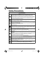
WIRED REMOTE CONTROLLER OPERATION MANUAL MODEL BRC1E61 Proper Use for Effective Energy Saving ● Thank you for purchasing the wired remote controller. ● This manual describes safety precautions required for the use of the product. Read this manual carefully and be sure you understand the information provided before attempting to use the product. Keep this manual where it is readily accessible after reading it through. If another user operates the product in the future, be sure to hand over this manual the new user. 00_CV_3P243520-1B.indd 1 5/15/2009 10:15:43 AM Contents Notices Safety Precautions Items to be Strictly Observed ......... 2 Names and Functions ............................................... 8 Simple Settings in Direct Buttons for Basic Operation Items Basic Operation Method Cool/Heat/Auto/Fan Operation .............................. 14 (Use of Direct Buttons) Program Dry Operation .......................................... 17 Home Leave ........................................................... 19 Ventilation Operation .............................................. 20 Setting Method of the Cooling/Heating Selection Eligibility ................................................................. 21 Key Lock ............................................................... 23 Ease of Cellular-like Function Settings Quick Reference of Main Menu Items Main Menu Items ................................................... 24 Menu Manipulation Manipulating the Main Menu Screen ..................... 26 Set temp mode changeover ................................... 27 Airflow Direction Setting ......................................... 28 Quick Cooling/Heating On/Off ................................ 31 Ventilation .............................................................. 32 Timer Settings ........................................................ 34 Service Contact/Model Information ........................ 44 Convenient Functions ............................................ 45 Setting Status List .................................................. 48 Clock Setting .......................................................... 48 Language changeover ........................................... 50 Maintenance Filter Sign Resetting ............................................... 51 Maintenance of Unit and LCD ................................ 52 Useful Information Error code Display ................................................. 53 After-sale Service ................................................... 54 English 01_EN_3P243520-1B.indd 1 1 5/15/2009 10:20:58 AM Safety Precautions Read the safety precautions attentively for the correct use of the product. ● The precautions described herein are classified as WARNING and CAUTION. They both contain important information regarding safety. Be sure to observe all precautions without fail. WARNING Failure to follow these instructions properly may result in personal injury or loss of life. CAUTION Failure to observe these instructions properly may result in property damage or personal injury, which may be serious depending on the circumstances. ● The following pictograms are used in this manual. Never do. Always follow the instructions given. Be sure to ground the unit. Absolutely keep wet hands away. Absolutely keep water and moisture away. About Remote Controller WARNING ● Do not install the remote controller by yourself. Improper installation may result in electric shocks or fire. Consult your Daikin dealer. ● Do not modify or repair the remote controller. This may result in electric shocks or fire. Consult your Daikin dealer. ● Do not relocate or reinstall the remote controller by yourself. Improper installation may result in electric shocks or fire. Consult your Daikin dealer. ● Do not use flammable materials (e.g., hairspray or insecticide) near the product. Do not clean the product with organic solvents such as paint thinner. The use of organic solvents may cause crack damage to the product, electric shocks, or fire. 2 01_EN_3P243520-1B.indd 2 English 5/15/2009 10:20:58 AM ――Items to be Strictly Observed―― CAUTION ● Do not play with the unit or its remote controller. Accidental operation by a child may result in impairment of bodily functions and harm health. ● Never disassemble the remote controller. Touching the interior parts may result in electric shocks or fire. Consult your Daikin dealer or authorized contractor for internal inspections and adjustments. ● To avoid electric shocks, do not operate with wet hands. ● Do not wash the remote controller. Doing so may cause electric leakage and result in electric shocks or fire. ● Do not leave the remote controller wherever there is a risk of wetting. If water gets into the remote controller there is a risk of electrical leakage and damage to electronic components. Indoor Unit and Outdoor Unit WARNING ● Be aware that prolonged, direct exposure to cool or warm air from the air conditioner, or to air that is too cool or too warm can be harmful to your physical condition and health. ● Do not place objects, including rods, your fingers, etc., in the air inlet or outlet. Injury may result due to contact with the air conditioner’s highspeed fan blades. ● Contact professional personnel about attachment of accessories and be sure to use only accessories specified by the manufacturer. If a defect results from your own workmanship, it may result in water leaks, electric shock or fire. ● Do not use the product in the atmosphere contaminated with oil vapor, such as cooking oil or machine oil vapor. Oil vapor may cause crack damage, electric shocks, or fire. ● Do not use the product in places with excessive oily smoke, such as cooking rooms, or in places with flammable gas, corrosive gas, or metal dust. Using the product in such places may cause fire or product failures. English 01_EN_3P243520-1B.indd 3 3 5/15/2009 10:20:58 AM Safety Precautions WARNING ● Beware of fire in case of refrigerant leakage. If the air conditioner is not operating correctly, i.e. not generating cool or warm air, refrigerant leakage could be the cause. Consult your dealer for assistance. The refrigerant within the air conditioner is safe and normally does not leak. However, in the event of a leakage, contact with a naked burner, heater or cooker may result in generation of noxious gas. Do not longer use the air conditioner until a qualified service person confirms that the leakage has been repaired. ● In the case of using a load breaker provided with a fuse, make sure that the capacity of the fuse is correct. Use of an ordinary conductive wire may cause malfunctions or fire. ● Do not start or stop operating the air conditioner with the power supply breaker turned ON or OFF. Otherwise, fire or water leakage may result. Furthermore, the fan will rotate abruptly if power failure compensation is enabled, which may result in injury. ● Be sure to earth the unit. Do not earth the unit to a utility pipe, lightning conductor or telephone earth lead. Imperfect earthing may result in electric shocks or fire. A high surge current from lightning or other sources may cause damage to the air conditioner. ● When the air conditioner is malfunctioning (giving off a burning odour, etc.) turn off power to the unit and contact your local dealer. Continued operation under such circumstances may result in a failure, electric shocks or fire hazards. ● Consult your local dealer regarding what to do in case of refrigerant leakage. When the air conditioner is to be installed in a small room, it is necessary to take proper measures so that the amount of any leaked refrigerant does not exceed the concentration limit in the event of a leakage. Otherwise, this may lead to an accident due to oxygen depletion. ● Be sure to install an earth leakage breaker. Failure to install an earth leakage breaker may result in electric shocks or fire. ● Consult the dealer if the air conditioner submerges owing to a natural disaster, such as a flood or typhoon. Do not operate the air conditioner in that case, or otherwise a malfunction, electric shock, or fire may result. ● Be sure to use a dedicated power supply for the air conditioner. The use of any other power supply may cause heat generation, fire, or product failures. 4 01_EN_3P243520-1B.indd 4 English 5/15/2009 10:20:59 AM ――Items to be Strictly Observed―― CAUTION ● After prolonged use, check the unit stand and its mounts for damage. If left in a damaged condition, the unit may fall and cause injury. ● Do not allow a child to mount on the outdoor unit or avoid placing any object on it. Falling or tumbling may result in injury. ● Do not block air inlets nor outlets. Impaired air flow may result in insufficient performance or trouble. ● To avoid injury, do not touch the air inlet or aluminium fins of the unit. ● Do not remove the outdoor unit’s fan guard. The guard protects against the unit’s high speed fan, which may cause injury. ● Do not place objects that are susceptible to moisture directly beneath the indoor or outdoor units. Under certain conditions, condensation on the main unit or refrigerant pipes, air filter dirt or drain blockage may cause dripping, resulting in fouling or failure of the object concerned. ● Do not place water containers (flower vases, etc.) on the unit, as this may result in electric shocks or fire. ● Do not use the air conditioner for purposes other than those for which it is intended. Do not use the air conditioner for cooling precision instruments, food, plants, animals or works of art as this may adversely affect the performance, quality and/or longevity of the object concerned. ● Do not place appliances that produce naked flames in places exposed to the air flow from the unit as this may impair combustion of the burner. ● Do not place heaters directly below the unit, as resulting heat can cause deformation. ● Be sure that children, plants or animals are not exposed directly to airflow from the unit, as adverse effects may ensue. ● Do not put flammable containers, such as spray cans, within 1m from the blow-off mouth. The containers may explode because the warm air output of the indoor or outdoor unit will affect them. ● Do not install the air conditioner at any place where there is a danger of flammable gas leakage. In the event of a gas leakage, build-up of gas near the air conditioner may result in fire hazards. English 01_EN_3P243520-1B.indd 5 5 5/15/2009 10:21:00 AM Safety Precautions CAUTION ● Do not sit or stand on any unstable base at the time of operating or maintaining the air conditioner. The base may topple down and injury may result. ● Do not touch the motor at the time of filter replacement. The motor in operation is at high temperatures and a burn may result. ● Do not wash the air conditioner with water, as this may result in electric shocks or fire. ● Perform ventilation from time to time. Be careful when using the air conditioner with other heating equipment. Insufficient ventilation may result in oxygen deficiency. ● Always stop the operation of the air conditioner and turn OFF the breaker at the time of cleaning. Failure to do so may result in an electric shock or injury. ● Do not wash the interior of the indoor and outdoor units by yourself. Always consult your Daikin dealer. The use of an incorrect washing method or incorrect detergent may damage the resin parts of the indoor unit or cause water leakage. Moreover, malfunctions, smoke generation, or ignition may result if the electric parts or motor in the indoor unit is wet with detergent. ● Do not place objects in direct proximity of the outdoor unit and do not let leaves and other debris accumulate around the unit. Leaves are a hotbed for small animals which can enter the unit. Once in the unit, such animals can cause malfunctions, smoke or fire when making contact with electrical parts. ● Fix the units securely. If the units are not mounted securely, the units may fall or topple and injury may result. ● Arrange the drain to ensure complete drainage. If proper drainage from the outdoor drain pipe does not occur during air conditioner operation, there could be a blockage due to dirt and debris build-up in the pipe. This may result in a water leakage from the indoor unit. Under these circumstances, stop air conditioner operation and consult your dealer for assistance. 6 01_EN_3P243520-1B.indd 6 English 5/15/2009 10:21:00 AM English 01_EN_3P243520-1B.indd 7 7 5/15/2009 10:21:01 AM Names and Functions 1. Operation mode selector button 11. LCD (with backlight) 4. Up button 5. Down button 6. Right button 7. Left button 9. Operation lamp 8. On/Off button 3. Menu/Enter button 10. Cancel button 2. Fan speed control button Functions other than basic operation items (i.e., On/Off, Operation mode selector, Fan speed control, and temperature settings) are set from the menu screen. NOTE ● Do not install the remote controller in places exposed to direct sunlight. Otherwise, the LCD may become discolored and nothing may be displayed. ● Do not pull or twist the remote controller cord. Otherwise, the remote controller may error. ● Do not press the buttons on the remote controller with objects with sharp ends. Otherwise, the remote controller may receive damage or error. 8 01_EN_3P243520-1B.indd 8 English 5/15/2009 10:21:01 AM 1. Operation mode selector button ● Press this button to select the operation mode of your preference. (See page 14.) * Available modes vary with the connecting model. 2. Fan speed control button ● Press this button to select the fan speed of your preference. (See page 15.) * Available fan speed vary with the connecting model. 3. Menu/Enter button ● Used to indicate the main menu. (See page 24 for the menu items.) ● Used to enter the setting item selected. 4. Up button (Be sure to press the part with the symbol ) ● Used to raise the set temperature. ● The next items on the upper side will be highlighted. (The highlighted items will be scrolled continuously when the button is kept pressed.) ● Used to change the item selected. 5. Down button (Be sure to press the part with the symbol ) ● Used to lower the set temperature. ● The next items on the lower side will be highlighted. (The highlighted items will be scrolled continuously when the button is kept pressed.) ● Used to change the item selected. 7. Left button (Be sure to press the part with the symbol ) ● Used to highlight the next items on the left-hand side. ● Each screen is scrolled in the left-hand direction. ● Home leave settings are enabled with this button kept pressed for at least four seconds. (See page 19.) 8. On/Off button ● Press this button and system will start. ● Press this button again and system will stop. 9. Operation lamp (Green) ● This lamp lights up during operation. ● This lamp blinks if a error occurs. 10.Cancel button ● Used to return to the previous screen. 11. LCD (with backlight) ● The backlight will be light for approximately 30 seconds by pressing any operation button. Operate buttons excluding the On/ Off button while the backlight is lit. ● If two remote controllers are used to control a single indoor unit, the backlight of the remote controller operated earlier than the other one will be lit. 6. Right button (Be sure to press the part with the symbol ) ● Used to highlight the next items on the right-hand side. ● Each screen is scrolled in the right-hand direction. ● Home leave settings are enabled with this button kept pressed for at least four seconds. (See page 19.) English 01_EN_3P243520-1B.indd 9 9 5/15/2009 10:21:01 AM Names and Functions Liquid Crystal Display ● Two types of liquid crystal display (LCD) are available. The standard display is by default set. ● To go to the detailed display, select the detailed display in the main menu. (See page 46.) ● The displayed contents of the screen vary with the operation mode of the equipment interlocked. (The following display will appear when the air conditioner is in automatic heating operation.) Standard display 11. Changeover under control 10.Under centralized control 1.Operation mode Auto 2.Automatic operation mode 3.Fan speed 7.Ventilation Heat 12.Home Leave 9.( ) display 8.( Set temperature 20°C This function not available <Standard display example> ) display 4.Set temperature display 5.Defrost/Hot start 6.Message Detailed display The airflow direction, clock, and detailed selection items appear on the detailed display screen in addition to the items appearing on the standard display. Auto 13.Airflow direction Heat (Displayed only when the air conditioner is in operation.) Return 14.Clock (24 hours real time clock) 12: 05 A Set temp Room 20°C 20°C Setting 15.Detailed selection (with room temperature settings) <Detailed display example 1> Clock display 3.Fan speed display (with no fan speed control function) (with no clock settings) Auto Heat Airflow direction display (with no airflow direction settings) 10 01_EN_3P243520-1B.indd 10 Return --:-- 16. ( 20°C Detailed selection A ) display Set temp (with no detailed items selected) Setting <Detailed display example 2> English 5/15/2009 10:21:01 AM 1. Operation mode “Error: Press Menu Button.” “Warning: Press Menu Button.” ● Displayed if the error or warning is detected (see page 53). ● Used to display the present operation mode Cool, Heat, Vent, Fan, Dry or Auto mode. “Quick Cool/Heat” (SkyAir only) ● Displayed if the quick cooling/heating function is turned ON (see page 31). 2. Automatic operation mode ● Used to display the present automatic operation mode (Cool or Heat). “Clean the filter.” “Clean the element.” “Clean the filter and element.” ● Displayed when the time to clean the filter or element has come (see page 51). 3. Fan speed ● Used to display the fan speed that is set for the air conditioner. ● The fan speed will not be displayed if the air conditioner does not have fan speed control function. 7. Ventilation / Purifying ● Displayed when a total heat exchanger unit, such as the Ventiair, is connected. ● Ventilation mode icon.“ ” These icons indicate the current ventilation mode (HRV only) (AUTOMATIC, HEAT EXCHANGE, BYPASS). ● AIR Purifying ICON “ ” This icon indicates that the air cleaning unit (option) is operational. 4. Set temperature display ● Used to display the temperature set for the air conditioner. 5. Defrost/Hot start “ ” (See page 16.) If Ventilating operation “ ” is displayed: ● Displayed when a total heat exchanger unit, such as the Ventiair, is connected. For details, refer to the Operation Manual of the Ventiair. 6. Message The following messages are displayed. “This function not available.” ● Displayed for a few seconds when an operation button is pressed if the indoor unit is not provided with the corresponding function. ● If a number of indoor units are in operation, the message will appear only if none of the indoor units is provided with the corresponding function, i.e., the message will not appear if at least one of the indoor units is provided with the corresponding function. English 01_EN_3P243520-1B.indd 11 8. display (See page 23.) ● Displayed when the key lock is set. 9. display (See page 34.) ● Displayed if the schedule timer or OFF reminder timer is enabled. 10.Under Centralized control “ ” ● Displayed if the system is under the management of central control equipment (optional accessories) and the operation of the system through the remote controller is prohibited. 11. Changeover under control “ ” (VRV only) ● Displayed on the remote controller if the remote controller has no cooling/heating selection eligibility mode (see page 21). 11 5/15/2009 10:21:02 AM Names and Functions 12.Home leave “ ” (See page 19.) ● The home leave icon shows the status of the home leave function. ON Home leave is enabled FLASHING Home Leave is active OFF Home Leave is disabled 13.Airflow direction “ ” ● Displayed when the airflow direction and swing are set (see page 28). ● This item is not displayed if the system is not provided with a function to set airflow directions. 14.Clock (24 hours real time clock) ● Displayed if the clock is set (see page 48). ● If the clock is not set, “ -- : -- ” will be displayed. 15.Detailed selection ● Displayed if the detailed display items are selected (see page 47). ● No detailed items are by default selected. 16. display ● Displayed to inform that the clock needs setting again. ● The schedule timer function will not work unless the clock is set again. 12 01_EN_3P243520-1B.indd 12 English 5/15/2009 10:21:03 AM English 01_EN_3P243520-1B.indd 13 13 5/15/2009 10:21:03 AM Basic Operation Method (Use of Direct Buttons) Cool/Heat/Auto/Fan Operation Remote Controller Functions Operation Method 1 Operation screen display MainMenu Return Describes screens that will be displayed on the remote controller in operation. 1/2 Set temp mode changeover Airflow Direction Quick Cool/Heat On/Off Ventilation Timer setting Service Contact/Model info Return Operation button display Displays the positions of buttons to be operated. ● Displays the main menu screen. buttons to select Timer setting on the main menu 2/2 Setting Explains a button operation procedure for the remote controller. Operate the buttons according to the procedure. (See page 26.) Disable Disable Schedule timer Off reminder timer Operation procedure ● Press Setting Timer setting (SkyAir and VRV) screen. Press Menu/Enter button to display the timer settings screen. * Items presently enabled or disabled are displayed. Preparation ● For mechanical protection purposes, turn ON the system at least six hours before starting the operation of the system. ● Do not turn OFF the system in season in order to ensure the smooth starting of the system. Operation Method 1 Cool Return Set temperature 28°C Setting ● Press Operation Mode Selector button several times until the desired mode Cooling, Heating, Fan, or Auto mode is selected. * Unavailable operation modes are not displayed. * Only the Cooling or Fan mode can be selected if the air conditioner is a cooling-only model. * The Auto mode can be set in the case of the VRV cooling/ heating simultaneous operation system. * Changeover under control will appear on each remote controller, but only the Cooling or Fan mode can be set in the case of the VRV cooling-only system. Note ● Before making a mode change, make sure that Changeover under control is not displayed on the remote controller. The cooling or heating mode cannot be selected if the above is displayed on the remote controller. See page 21 if Changeover under control display blinks. 14 01_EN_3P243520-1B.indd 14 English 5/15/2009 10:21:03 AM 2 3 ● Press On/Off button. The Operation lamp (green) will be lit and the system will start operating. Cool Set temperature 28°C Return Setting ● The set temperature will increase by 1°C when button is pressed and decrease by 1°C when button is pressed. * No temperature settings are possible while in fan mode. 4 Cool Set temperature 28°C Return Setting Low Middle High 5 ● To make fan speed control, press Fan speed control button and select the desired fan speed from Low, Middle or High. * Two fan speed adjustment levels Low, High may be available depending on the type of indoor unit. * The system may be in automatic fan speed control for mechanical protection purposes. * The system may be in automatic fan speed control according to the room temperature. The fan may stop operating, which, however, is not a failure. * The completion of fan speed selection may take time, which, however, is not a failure. ● Make airflow direction settings from the main menu (see page 28). * The airflow direction of the system cannot be changed unless the system is provided with a function to allow airflow direction changes. English 01_EN_3P243520-1B.indd 15 15 5/15/2009 10:21:03 AM Basic Operation Method (Use of Direct Buttons) 6 ● The Operation lamp will be turned OFF and the system will stop operating when On/Off button is pressed again. * While the system is in heating operation, the system will be in fan operation for approximately one minute in order to eliminate the heat in the indoor unit after the heating operation comes to a stop. Note ● Do not turn power OFF soon after the system stops operating. Be sure to wait for at least five minutes so that the drain discharging device will finish discharging the residual drain. Otherwise, water leakage or failures may result. Characteristics of Heating Operation Starting operation ● The system in heating operation generally requires a long time to attain the set temperature compared with the system in cooling operation. It is recommended to start operating the system in advance by utilizing the timer. Perform the following operation of the system in order to prevent the degradation of the heating capability or cold winds from blowing out. Defrosting operation ● The heating capability of the system will drop if the outdoor unit frosts up. Therefore, the system will go into defrosting operation automatically. ● The system will stop blowing out hot air, and “ ” (Defrost/Hot start) will be displayed on the remote controller. ● The system will return to normal operation with an elapse of approximately six to eight minutes (but not more than 10 minutes). Hot start (VRV only) ● When the system goes into heating operation, the wind will stop in order to prevent cold air from blowing out of the system in defrosting operation. (In that case, “ ” (Defrost/Hot start) will be displayed on the remote controller.) 16 01_EN_3P243520-1B.indd 16 English 5/15/2009 10:21:04 AM Outdoor temperature and heating capability ● The heating capability of the system will drop with a decrease in outdoor temperature. If that happens, use the system along with another heating appliance. (In the above case, be sure to ventilate the room as frequently as possible.) Do not use the heating appliance in places where the heating appliance is exposed to the wind from the system. ● The system is of hot air circulation type. Therefore, it takes some time for the room to become warm after the system starts operating. The indoor fan will automatically go into breezing operation until the inner temperature of the system rises to a certain level. ● If the hot air stays around the ceiling and your feet feel cold, the use of a circulator is recommended. For details, consult your Daikin dealer. Program Dry Operation Preparation ● For mechanical protection purposes, turn ON the system at least six hours before starting the operation of the system. ● Do not turn OFF the system in season in order to ensure the smooth starting of the system. ● The dry mode may not be selected if the remote controller has no right to select cooling/ heating mode (see page 22 for details). Operation Method 1 Dry Set temperature 28°C Return English 01_EN_3P243520-1B.indd 17 Setting ● Press Operation Mode Selector button several times until the Dry operation is selected. * The dry operation may not be available depending on the type of indoor unit. 17 5/15/2009 10:21:04 AM Basic Operation Method (Use of Direct Buttons) 2 ● Press On/Off button. The Operation lamp (green) will be lit and the system will start operating. * The microcomputer is in automatic temperature and fan speed control. Therefore, temperature or fan speed settings cannot be made or changed while the air conditioner is in operation. 3 ● Make airflow direction settings from the main menu (see page 28). * The airflow direction of the system cannot be changed unless the system is provided with a function to allow airflow direction changes. 4 ● The Operation lamp will be turned OFF and the system will stop operating when On/Off button is pressed again. Note ● Do not turn power OFF soon after the system stops operating. Be sure to wait for at least five minutes so that the drain discharging device will finish discharging the residual drain. Otherwise, water leakage or failures may result. 18 01_EN_3P243520-1B.indd 18 English 5/15/2009 10:21:05 AM Operation Contents Program Dry The Program dry function of the system repeats the weak cooling operation of the system intermittently to dehumidify the room without dropping the room temperature as much as possible for the prevention of excessive cooling. Program Dry Operation ● The microcomputer is in automatic temperature and fan speed control. Therefore, temperature or fan speed settings cannot be made or changed while the air conditioner is in operation. Home Leave Home Leave is a feature that enables to keep the room temperature above 10°C when the occupants are out. Note ● This function will switch on heating if the installation is switched off. Operation Method 1 Cool Return Cool Return The home leave can not be enabled when a centralized control is connected. Set temperature 28°C Setting Set temperature 28°C Setting ● Press and hold the “ ” or “ ” button for at least four seconds. (During backlight lit) ● The Home Leave icon displays and function is enabled. The Home Leave icon shows the status of the home leave function. ON Home leave is enabled FLASHING Home leave is active OFF Home leave is disabled ● To cancel the home leave mode, continue pressing “ ” or “ ” button for at least four seconds. (During backlight lit) English 01_EN_3P243520-1B.indd 19 19 5/15/2009 10:21:05 AM Basic Operation Method (Use of Direct Buttons) Ventilation Operation When Air Conditioner Interlocked with Total Heat Exchanger Preparation ● For mechanical protection purposes, turn ON the system at least six hours before starting the operation of the system. ● Do not turn OFF the system in season in order to ensure the smooth starting of the system. Operation Method 1 Vent Return 2 Set temperature 20°C Setting ● Set the Operation mode selector button to Ventilation in the case of operating the total heat exchanger without the system between seasons. ● To change the ventilation mode setting, make necessary settings from the main menu (see page 33). * Ventilation mode: Automatic, Heat exchange, and Bypass 3 ● To change the ventilation rate, make necessary settings from the main menu (see page 32). * Ventilation rate: Low or High 4 5 20 01_EN_3P243520-1B.indd 20 ● Press On/Off button. The Operation lamp (green) will be lit and the system will start operating. ● The Operation lamp will be turned OFF and the system will stop operating when On/Off button is pressed again. English 5/15/2009 10:21:05 AM Setting Method of the Cooling/Heating Selection Eligibility (VRV only) Setting Changes 1 Cool Set temperature 28°C Return Cool See page 22 for an explanation of the cooling/heating selection eligibility. Setting Set temperature 28°C Return Setting ● Continue pressing Operation Mode Selector button of the remote controller for at least four seconds. (During backlight lit) A remote controller will not display “ ” (Changeover under control) if a cooling/heating selection eligibility is granted to the remote controller. ● The display “ ” (Changeover under control) on each remote controller connected to the same outdoor unit or BS unit will start blinking. * Vent mode setting changes are possible regardless of the cooling/heating selection eligibility. * If a cooling/heating selection eligibility is set in the cooling/ heating selection remote controller ( ), all the remote controllers will display “ ” (Changeover under control). In this case, no cooling/heating selection eligibility can be set in the remote controllers. Refer to the operation manual provided to the outdoor unit for the details of the cooling/heating selection remote controller. ● Set a cooling/heating selection eligibility as explained below. Selection Settings 2 Cool Return Cool Return English 01_EN_3P243520-1B.indd 21 The display “ Set temperature 28°C Setting Set temperature 28°C Setting ” (Changeover under control) will blink when the power is turned ON for the first time. ● Press Operation Mode Selector button of the remote controller for which the selection eligibility to be set. Then the cooling/heating selection eligibility will be set and the display “ ” (Changeover under control) will disappear. The display “ ” (Changeover under control) will appear on the other remote controllers. 21 5/15/2009 10:21:06 AM Basic Operation Method (Use of Direct Buttons) Operation Selection 3 Cool Return Set temperature 28°C Setting ● Press the remote controller that has the cooling/heating selection eligibility (or the remote controller without the display ” (Changeover under control)) “ several times until the desired mode is selected. The display will change to “Fan”, “Dry”, “Auto”, “Cool”, “Heat” each time the button is pressed. ● The display “Auto” will appear for the heating/cooling simultaneous operation system only. At that time, the other remote controllers with no selection right will follow suit and change the display automatically. Cool/Heat Selection Eligibility ● The “Cool”, “Heat”, “Auto” can be set for only the remote controller for which the cooling/heating selection eligibility is set. (The display “Auto” will appear for the heating/cooling simultaneous operation system only.) 1. The remote controller with the selection eligibility ” (without “ (Changeover under control) displayed) Set to “Cool”, “Heat”, “Dry”, “Auto” mode. Other remote controllers (with “ ” (Changeover under control) displayed) ● The system will go into the mode set in the remote controller. No other modes are available. ● The system, however, can be switched to fan mode or from “Cool” to “Dry”. 2. The remote controller with the selection eligibility ” (without “ (Changeover under control) displayed) Other remote controllers Set to “Fan” mode. (with “ ” (Changeover under control) displayed) ● The system cannot be set to other modes except fan mode. 22 01_EN_3P243520-1B.indd 22 English 5/15/2009 10:21:07 AM Precautions for Setting Cooling/Heating Selection Eligibility ● The cooling/heating selection eligibility needs to be set for a single remote controller in the following case. (Cooling/Heating selected operation system) (Cooling/Heating simultaneous operation system) BS unit: The BS unit is used for cooling or heating mode selection. Indoor unit Indoor unit A number of indoor units are connected to a single outdoor unit. A single BS unit is connected to a number of indoor units. Set the cooling/heating/fan selection eligibility in one of the remote controllers. Set the cooling/heating/auto/fan selection eligibility in one of the remote controllers. Key Lock Operation Method 1 Cool Return Make settings and cancel settings in the basic screen. Set temperature 28°C ● Continue pressing Menu/Enter button for at least four seconds. (During backlight lit) Setting Basic screen 2 Cool Return English 01_EN_3P243520-1B.indd 23 Set temperature 28°C Setting ● “ ” will appear. All buttons are disabled when the keys are locked. ● To cancel the key lock mode, continue pressing Menu/Enter button for at least four seconds. (During backlight lit) 23 5/15/2009 10:21:08 AM Quick Reference of Main Menu Items The main menu has the following items. Setting and display items Description Reference page Set temp mode changeover Select normal set temperature or limit control. 27 Airflow direction setting Used to make airflow direction settings. ● The airflow direction blade are automatically operated up and down (left and right). ● The fixed airflow directions are set to five positions. 28 * This function is not available to all models. Used to set the room to a conformable temperature quickly (unless the system is not in program dry or fan operation). ● The maximum quick cooling/heating operation period is 30 minutes. 31 Ventilation rate Used to set to “Low” “High” 32 Ventilation mode Used to set Automatic, Heat exchange, and Bypass. 33 Quick Cooling/Heating On/Off (SkyAir only) Ventilation Ventilation operation settings for total heat exchanger Timer setting Schedule timer ● Operation start time and stop time can be set according to the day of the week. Either one of the following operation modes can be selected. • Operation at set temperature: Normal operation • Operation within set temperature range (between max. and min. temperatures): Limit operation Up to 5 actions can be set for each day. ● Convenient holiday settings and temporary closure settings are possible. 35 * Clock settings are necessary. * The system goes into schedule timer operation in the previous mode set for the system. Off reminder timer Used to set each operation period of the system. ● Possible to set in 10 minute units from 30 to 180 minutes. Service Contact/Model Information 24 01_EN_3P243520-1B.indd 24 Used to display the service contact and model information. 42 44 English 5/15/2009 10:21:11 AM Setting and display items Convenient functions Description Reference page Contrast adjustment Used to make LCD contrast adjustment. Display changeover Used to set to standard or detailed display mode. Standard or detailed display 45 ● Display Standard or detailed display ● Detailed display settings Selectable from the display room temperature, outdoor temperature, system, or without any display items. Setting status list ● Used to display a list of current settings for available items. Clock setting Used to make date and time settings and corrections. 46 48 ● The clock is in 24 hours real time clock. ● The accuracy of the clock is within ±30 seconds per month. ● If there is a power failure for a period not exceeding 48 hours, the clock will continue working with the built-in backup power supply. The clock needs settings again if the power failure period exceeds 48 hours. Language changeover 48 The displayed language can be selected from the following language. (English/Deutsch/ Français/Español/Italiano/Eλληνικά/ Nederlands/Portugues/Pyccĸий/Тürkçe) 50 Note: Available setting items vary with the model connected. Only the available setting items appear in the menu. Menu Items of Sub Remote Controller Indoor unit If two remote controllers are in control of a single indoor unit, the following menu items are not set in the sub remote controller. Set them in the main remote controller. ● Set temp mode changeover ● Schedule timer ● Off reminder timer ● Home leave English 01_EN_3P243520-1B.indd 25 Outdoor unit Two remote controllers in control 25 5/15/2009 10:21:12 AM Menu Manipulation Manipulating the Main Menu Screen Display Method for Main Menu Operation Method 1 ● Press Menu/Enter button. Cool Return Set temperature 28°C Setting Basic screen 2 MainMenu 1/2 Set temp mode changeover Airflow Direction Quick Cool/Heat On/Off Ventilation Timer setting Service Contact/Model Info Return Setting Main menu screen 3 ● The main menu screen will appear. Instructions for manipulating the buttons will appear. ● Selecting items from the main menu. 1. Press buttons to select the desired item to be set. 2. Press Menu/Enter button to display the selected settings screen. 4 ● To go back to the basic screen from the main menu screen, press the Cancel button. Caution ● While setting items, if a button is not pressed for 5 minutes, the screen will automatically go back to the basic screen. 26 01_EN_3P243520-1B.indd 26 English 5/15/2009 10:21:12 AM Set temp mode changeover Limit Operation Limit operation provides thermostat control within the range of the set minimum and maximum temperature. The minimum temperature setting will trigger heating. The maximum temperature setting will trigger cooling. Operation Method 1 The limit operation can not be enabled when a centralized control is connected. MainMenu 1/2 Set temp mode changeover Airflow Direction Quick Cool/Heat On/Off Ventilation Timer setting Service Contact/Model Info Return Fan Setting Set temperature max min 28 °C 20 °C Return Press the menu button Basic screen 2 Fan Set temperature max min 28 °C 20 °C Return Press the menu button ● Display the main menu screen. (See page 26.) ● Press buttons to select “Set temp mode changeover” on the main menu screen. ● Pressing Menu/Enter button takes you back to the basic screen, and the set temperature is displayed in max °C min °C. (Limit Operation) * To return to the normal set temperature screen, use “Set temp mode changeover” in the Main Menu again. ● To change the set temperature, press buttons. The set temperature is highlighted and ready to be changed. ● The set temperature will increase by 1°C when the button is pressed and decrease by 1°C when the button is pressed. Note ● The difference between the maximum and minimum temperatures cannot be set to less than 6°C. (* Maximum temperature – Minimum temperature ≥ 6°C) 3 Fan Set temperature max min 28 °C 20 °C ● Pressing buttons switches the variable set temperature between max. and min. Return Press the menu button English 01_EN_3P243520-1B.indd 27 27 5/15/2009 10:21:13 AM Menu Manipulation Airflow Direction Setting Manipulating Airflow Direction Setting Operation Method 1 MainMenu 1/2 Set temp mode changeover Airflow Direction Quick Cool/Heat On/Off Ventilation Timer setting Service Contact/Model Info Return Setting ● Display the main menu screen. (See page 26.) ● Press buttons to select Airflow Direction on the main menu screen and press the Menu/Enter button. (For models with no airflow direction adjustment, Airflow Direction will not be displayed on the main menu screen.) 2 Airflow Direction Swing Return Setting Airflow direction setting (up/down) Airflow Direction Note ● Airflow direction appears on the screen as below. 0 1 0 2 3 4 Up/down direction Swing Return ● The airflow direction setting screen will appear. 4 1 2 3 Left/right direction 0 1 2 3 4 : Position : Position : Position : Position : Position 0 1 2 3 4 Setting Airflow direction setting (left/right) 28 01_EN_3P243520-1B.indd 28 English 5/15/2009 10:21:13 AM 3 Airflow Direction Swing Return Setting Up/down direction Airflow Direction Swing Return Setting Left/right direction 4 Airflow Direction Position 2 Return Setting Up/down direction Airflow Direction Position 2 Return Setting ● Pressing buttons changes the setting to (in order) Swing , Position 0 , Position 1 , Position 2 , Position 3 , and Position 4 . ● Selecting Swing will cause the airflow direction blades to swing back and forth. For the swing setting only, all positions will be displayed. ● When you select one of positions 0 to 4, the airflow direction blades stay in a fixed position. * The illustration is a display when position 2 is selected. ● Press buttons to select the desired airflow direction. Press Menu/Enter button to return to the basic screen. Left/right direction English 01_EN_3P243520-1B.indd 29 29 5/15/2009 10:21:14 AM Menu Manipulation Operational Details and Functions There are two types of airflow direction setting. Airflow direction swing The airflow direction blades automatically swing up and down. Indoor unit (Automatic) Airflow direction You can select from one of five fixed directions. (This has no relation to the angle of the louvers.) Indoor unit (Automatic) (Desired position) (Desired position) Movement of airflow direction blades Under the operation conditions shown below, airflow direction is controlled automatically. Actual operation may thus be different than what is displayed on the remote controller. Operation condition ● Room temperature is higher than the remote controller’s set temperature (in heating mode). ● When defrosting (in heating mode). (The airflow is blowing horizontally so that people in the room are not in direct line of the cold air.) ● Under continuous operation with the airflow blowing horizontally. Heating mode includes automatic operation. 30 01_EN_3P243520-1B.indd 30 English 5/15/2009 10:21:15 AM Quick Cooling/Heating On/Off Quick Cooling/Heating On Operation Method 1 MainMenu 1/2 Set temp mode changeover Airflow Direction Quick Cool/Heat On/Off Ventilation Timer setting Service Contact/Model Info Return Cool Setting Set temperature 28°C Quick Cool/Heat ● While operating in Cooling, Heating, or Auto mode, display the main menu screen (see page 26). ● Press buttons to select Quick Cool/Heat On/Off on the main menu screen. Press Menu/Enter button to return to the basic screen. ● Quick Cooling/Heating will appear on the basic screen. Quick Cooling/Heating is now on. Quick Cooling/Heating Off Operation Method 2 MainMenu 1/2 Set temp mode changeover Airflow Direction Quick Cool/Heat On/Off Ventilation Timer setting Service Contact/Model Info Return Cool Return English 01_EN_3P243520-1B.indd 31 Setting Set temperature 28°C Setting ● While Quick Cooling/Heating is displayed on the basic screen, display the main menu screen (see page 26). ● Press buttons to select Quick Cool/Heat On/Off on the main menu screen. Press Menu/Enter button to return to the basic screen. ● Quick Cooling/Heating will no longer appear on the basic screen. ● Quick Cooling/Heating is now off. 31 5/15/2009 10:21:15 AM Menu Manipulation Quick Cooling/Heating Quick Cooling/Heating The indoor unit is automatically controlled, increasing the power of the outdoor unit and quickly bringing the room to a comfortable temperature. ● Fan speed display goes off and fan speed can no longer be switched. ● Cannot be set when in fan and dry modes. ● Quick Cooling/Heating mode will run for a maximum of 30 minutes before the unit automatically returns to normal operation. ● Activating mode selector will return the air conditioner to normal operation. ● In heating mode, fan speed may increase and the wind temperature may decrease. Adjust the operation as desired. Ventilation Display method for ventilation settings screen Operation Method 1 MainMenu 1/2 Set temp mode changeover Airflow Direction Quick Cool/Heat On/Off Ventilation Timer setting Service Contact/Model Info Return (See page 26.) ● Press buttons to select Ventilation on the main menu screen. Setting Ventilation 2/2 Ventilation rate Ventilation mode Return ● Display the main menu screen. (For models with no ventilation function, Ventilation will not be displayed on the main menu screen.) Press Menu/Enter button to display the ventilation settings screen. Setting Changing the ventilation rate Operation Method 1 Ventilation 2/2 Ventilation rate Ventilation mode Return 32 01_EN_3P243520-1B.indd 32 Setting ● Bring up the ventilation settings screen (see above). ● Press buttons to select Ventilation rate on the ventilation settings screen. Press Menu/Enter button to display the ventilation rate settings screen. English 5/15/2009 10:21:16 AM 2 ● Pressing buttons changes the setting to in order Low and High . Ventilation Ventilation rate High * Only modes that can be set are displayed. Return Setting Low High 3 ● Selecting the desired ventilation rate and pressing Menu/Enter button selects the setting and takes you back to the basic screen. (Pressing Cancel button takes you back to the previous screen without changing the ventilation rate.) Changing ventilation mode Operation Method 1 Ventilation Return 2 2/2 Ventilation rate Ventilation mode ● Display the ventilation settings screen. (See page 32.) ● Press buttons to select Ventilation mode on the ventilation settings screen. Press Menu/Enter button to display the ventilation mode settings screen. Setting Ventilation 2/2 Ventilation mode Bypass ● Pressing buttons changes the settings in order as shown below. Bypass Return Heat exchange Automatic Setting * Only modes that can be set are displayed. English 01_EN_3P243520-1B.indd 33 33 5/15/2009 10:21:16 AM Menu Manipulation 3 Cool Return Set temperature 28°C Setting ● Selecting the desired ventilation mode and pressing Menu/Enter button enters the settings and takes you back to the basic screen. (Pressing the Cancel button takes you back to the previous screen without changing the ventilation mode. ) Ventilation Mode Automatic mode Using information from the air conditioner (cooling, heating, fan, and set temperature) and the total heat exchanger unit (indoor and outdoor temperatures), mode is automatically changed between Heat exchanger and Bypass. Heat exchange mode Bypass mode Outside air undergoes Heat exchange and is supplied to inside the room. Outside air is supplied to inside the room without undergoing heat exchange. Timer Settings Display method for timer settings screen Operation Method 1 MainMenu 1/2 Set temp mode changeover Airflow Direction Quick Cool/Heat On/Off Ventilation Timer setting Service Contact/Model info Return (See page 26.) Setting Timer setting 2/2 Schedule timer Off reminder timer ● Display the main menu screen. Disable Disable ● Press buttons to select Timer setting on the main menu screen. Press Menu/Enter button to display the timer settings screen. * Currently enabled/disabled is displayed. Return Cool Return 34 01_EN_3P243520-1B.indd 34 Setting Set temperature 28°C ● When either schedule timer or off reminder timer is enabled, appears on the basic screen. Setting English 5/15/2009 10:21:17 AM Setting the schedule timer Display method for the schedule timer settings screen Operation Method 1 Timer setting 2/2 Schedule timer Off reminder timer Return Disable Disable Setting Schedule timer Clock setting is not carried out. Do you want to set? Yes Return No Setting Clock setting Year 2008 Month 01 Day 01 Tuesday 00:00 Return 2 Setting Schedule timer Enable/Disable setting Condition setting Holiday setting Return English 01_EN_3P243520-1B.indd 35 The schedule timer can not be enabled when a centralized control is connected. Setting ● Bring up the timer settings screen. (See page 34.) ● Press buttons to select the Schedule timer on the timer settings screen. Press Menu/Enter button to display the schedule timer settings screen. ● Before setting the schedule timer, the clock must be set. ● If the clock has not been set, a screen like the one on the left will appear. Press buttons to select Yes and press Menu/Enter button. Set the current year, month, day, and time. (See clock settings on page 48.) ● Press buttons to select the desired setting items on the schedule timer settings screen and press Menu/Enter button. 35 5/15/2009 10:21:18 AM Menu Manipulation Schedule timer Condition setting Operation Method 1 Schedule timer Return 2 2/2 Enable/Disable setting Condition setting Holiday setting Setting Schedule timer Sunday Time ––:–– ––:–– ––:–– ––:–– ––:–– Return Operation – – – – – Setting ● Display the schedule timer settings screen. (See page 35.) ● Press buttons to select Condition setting on the schedule timer settings screen. Press Menu/Enter button to display the condition setting screen. ● Press buttons to select the day to be set on the condition setting screen. ● Input the program for the selected day next. The schedule timer can accept a maximum of 5 operations per day. 3 Schedule timer Monday Time 06:00 ––:–– ––:–– ––:–– ––:–– Return Operation – – – – – Setting Schedule timer Monday Time 06:00 ––:–– ––:–– ––:–– ––:–– Return 36 01_EN_3P243520-1B.indd 36 Operation – – – – – ● Press buttons to move the highlighted item and press buttons to input the desired operation start time. Each press of buttons moves the numbers by 1 hour or 1 minute. Holding down the button causes the number to change continuously. Setting English 5/15/2009 10:21:19 AM 4 Schedule timer Monday Time 06:00 ––:–– ––:–– ––:–– ––:–– Return Operation 22°C – – – – Setting ● Press buttons to move the highlighted item and press buttons to select the desired operation. The following three types of operations are available. *1. switch on the installation at a scheduled time, in combination with a set point (exact temperature control) *2. switch on the installation at a scheduled time, in limit operation *3. switch off the installation (end of control) * The status remain unchanged in the case of “–”. The display changes in sequence as shown below when buttons are pressed. — 22°C 20°C-26°C OFF * *1 *2 *3 ● To make an operation change at set temperature, press buttons to move the highlighted item and press buttons to set the operation to 22°C . Schedule timer Monday Time 06:00 ––:–– ––:–– ––:–– ––:–– Return Operation 22°C – – – – Setting Schedule timer Monday Time 06:00 ––:–– ––:–– ––:–– ––:–– Return Operation 28°C – – – – Setting Schedule timer Monday Time 06:00 ––:–– ––:–– ––:–– ––:–– Return English 01_EN_3P243520-1B.indd 37 Operation 28°C – – – – ● To change the set temperature, press the Menu/Enter button so that the set temperature will be highlighted and ready to be changed. ● Press buttons to change the set temperature. The set temperature will increase by 1°C when the button is pressed and decrease by 1°C when the button is pressed. ● Pressing Menu/Enter button enters the set temperature change. Setting 37 5/15/2009 10:21:20 AM Menu Manipulation 5 Schedule timer Monday Time 06:00 12:30 ––:–– ––:–– ––:–– Return Operation 28°C 20°C–26°C – – – Setting Schedule timer Monday Time 06:00 12:30 ––:–– ––:–– ––:–– Return Operation 28°C 20°C–26°C – – – Setting Schedule timer Monday Time 06:00 12:30 ––:–– ––:–– ––:–– Return Operation 28°C 20°C– 26°C – – – Time 06:00 12:30 ––:–– ––:–– ––:–– Return Operation 28°C 20°C– 28°C – – – Setting Schedule timer Monday ● To change the maximum and minimum temperatures, press the Menu/Enter button so that the temperatures will be ready to be changed. ● Press buttons to select the desired temperature to be changed. Setting Schedule timer Monday ● To make limit operation settings, press buttons to move the highlighted item and press buttons to input the desired set time. ● Press buttons to move the highlighted item and press buttons to set the operation to 20°C - 26°C . Time 06:00 12:30 ––:–– ––:–– ––:–– Return Operation 28°C 22°C– 28°C – – – Setting ● Press buttons to change the set temperature. The set temperature will increase by 1°C when the button is pressed and decrease by 1°C when the button is pressed. Note ● The difference between the maximum and minimum temperatures cannot be set to less than 6°C. (* Maximum temperature – Minimum temperature ≥ 6°C) ● Pressing Menu/Enter button enters the set temperature change. 38 01_EN_3P243520-1B.indd 38 English 5/15/2009 10:21:21 AM 6 Schedule timer Monday Time 06:00 12:30 15:00 ––:–– ––:–– Return Operation 28°C 22°C– 28°C OFF – – Setting 7 ● To make operation stop settings, press buttons to move the highlighted item and press buttons to input the desired operation stop time. ● Press buttons to move the highlighted item and press buttons to turn OFF the operation. ● To set a different day of the week, press buttons to highlight the day presently set. ● Press buttons to change the day and input the program in the same manner. * To copy the settings for the previous day, select the operation mode selector button so that the settings will be copied as they are. Example: The contents for Monday are copied by pressing the operation mode selector button after selecting Tuesday. 8 Schedule timer Monday Time 06:00 12:30 15:00 ––:–– ––:–– Return Operation 28°C 22°C– 28°C OFF – – Setting Schedule timer Is it settled by setting? Yes Return English 01_EN_3P243520-1B.indd 39 No Setting ● When the entire day settings are completed, highlight the items other than the operation and press the Menu/Enter button. The settings confirmation screen will appear. ● Press button to select Yes on the settings confirmation screen. Pressing Menu/Enter button enters the schedule timer settings and takes you back to the basic screen. 39 5/15/2009 10:21:22 AM Menu Manipulation Holiday setting (The schedule timer will be disabled for days that have been set as holiday.) Operation Method 1 Schedule timer Enable/Disable setting Condition setting Holiday setting Return 2 Setting Schedule timer Holiday setting Multi selection possible Sun Mon Tue Wed Thu Fri Sat Return Setting ● Bring up the schedule timer settings screen. (See page 35.) ● Press buttons to select Holiday setting on the schedule timer settings screen. Press Menu/Enter button to display the holiday settings screen. ● Press buttons to select the desired day. Press buttons to display “ ” to make the holiday settings. Pressing buttons switches the setting between set and release. Multiple days can be selected as holidays. Note: To able the schedule timer for the day selected as a holiday, the holiday setting must be released. 3 Schedule timer Holiday setting Multi selection possible Sun Mon Tue Wed Thu Fri Sat Return 4 Setting Schedule timer Is it settled by setting? Yes Return 40 01_EN_3P243520-1B.indd 40 No Setting ● To complete the holiday settings, press Menu/Enter button. The settings confirmation screen will appear. ● Press button to select Yes on the settings confirmation screen. Pressing Menu/Enter button enters the holiday settings and takes you back to the schedule timer settings screen. English 5/15/2009 10:21:22 AM Schedule timer Sunday Holiday Time ––:–– ––:–– ––:–– ––:–– ––:–– Return Operation – – – – – ● Holiday that are set will be displayed on the condition settings screen. Setting Enabling or disabling the schedule timer without changing the set day or time Operation Method 1 Schedule timer Enable/Disable setting Condition setting Holiday setting Return 2 Setting Schedule timer Enable/Disable setting Disable Return 3 Setting Schedule timer Is it settled by setting? Yes Return English 01_EN_3P243520-1B.indd 41 No Setting ● Bring up the schedule timer settings screen. (See page 35.) ● Press buttons to select Enable/Disable setting on the schedule timer settings screen. Press Menu/Enter button to display the enable/disable settings screen. ● Press buttons to select Enable or Disable on the enable/disable settings screen. Press Menu/Enter button after selecting the item. Then the settings confirmation screen will appear. ● Press button to select Yes on the settings confirmation screen. Pressing Menu/Enter button enters the enable/disable settings for the schedule timer and takes you back to the basic screen. 41 5/15/2009 10:21:23 AM Menu Manipulation Making and checking the off reminder timer settings Operation Method 1 Schedule timer Off reminder Timer Return 2 Disable Disable Setting Off reminder Timer Enable/ Disable setting Condition setting Return 3 ● Bring up the timer settings screen. Timer setting Setting Off reminder Timer Each time after pressing the operation button, automatically stops after 60 minutes. Return 4 Setting Off reminder Timer Is it settled by setting? Yes Return 42 01_EN_3P243520-1B.indd 42 No Setting (See page 34.) ● Press buttons to select the Off reminder timer on the timer settings screen. Press Menu/Enter button to display the off reminder timer settings screen. ● Press buttons to select Condition setting on the off reminder timer settings screen. Press Menu/Enter button to display the condition settings screen. ● Use buttons to set the time from operation start until the unit automatically stops. Selections can be made in increments of 10 minutes from 30 to 180 minutes. Holding down the button causes the number to change continuously. ● Select the desired time and press Menu/ Enter button. The settings confirmation screen will appear. ● Press button to select Yes on the settings confirmation screen. Pressing Menu/Enter button enters the off reminder timer settings and takes you back to the basic screen. English 5/15/2009 10:21:24 AM Enabling or disabling the off reminder timer without changing the set time Operation Method 1 Off reminder Timer Enable/ Disable setting Condition setting Return 2 Setting Off reminder Timer Enable/ Disable setting Disable Return 3 Setting Off reminder Timer Is it settled by setting? Yes Return English 01_EN_3P243520-1B.indd 43 No Setting ● Bring up the off reminder timer settings screen. (See page 42.) ● Press buttons to select Enable/Disable setting on the off reminder timer settings screen. Press Menu/Enter button to display the enable/disable settings screen. ● Press buttons to select Enable or Disable on the enable/disable settings screen. Press Menu/Enter button after selecting the item. Then the settings confirmation screen will appear. ● Press button to select Yes on the settings confirmation screen. Pressing Menu/Enter button enters the enable/disable settings for the off reminder timer settings and takes you back to the basic screen. 43 5/15/2009 10:21:25 AM Menu Manipulation Service Contact/Model Information Display method for service contact and model information Operation Method 1 MainMenu Return 2 1/2 Set temp mode changeover Airflow Direction Quick Cool/Heat On/Off Ventilation Timer setting Service Contact/Model Info Setting Service Contact/Model Info Contact address 0123–456–7890 Indoor unit Outdoor unit Return –––/000 –––/000 Setting ● Display the main menu screen. (See page 26.) ● Press buttons to select Service Contact/Model Info on the main menu screen and press Menu/ Enter button. ● The phone number for the contact address will appear at the top of the screen. (If you have not yet registered your product, it will not appear. ) ● The model information of the indoor and outdoor units of your product will appear on the bottom of the screen. (For some models the product code may appear. ) * The model name will not appear if you have had the circuit board replaced. * The error code record may also appear. If it is not blinking, the unit is working properly. The error code record will disappear if you press On/Off button for more than 4 seconds. 44 01_EN_3P243520-1B.indd 44 English 5/15/2009 10:21:26 AM Convenient Functions Contrast Adjustment Operation Method 1 MainMenu Return 2 Setting Convenient functions Contrast adjustment Display changeover Return 3 2/2 Convenient functions Setting status list Clock setting Language changeover Setting Contrast adjustment Adjusts contrast Dark Light Return English 01_EN_3P243520-1B.indd 45 Setting ● Display the main menu screen. (See page 26.) ● Press buttons to select Convenient functions on the main menu screen. Press Menu/Enter button to display the convenient functions settings screen. ● Bring up the convenient functions settings screen. ● Press buttons to select Contrast adjustment on the convenient functions settings screen. Press Menu/Enter button to display the contrast adjustment settings screen. ● On the contrast adjustment settings screen press buttons until you reach the desired contrast. After setting, press Menu/Enter button and return to the basic screen. 45 5/15/2009 10:21:26 AM Menu Manipulation Display chageover Display selection Operation Method 1 Contrast adjustment Display changeover Return 2 Setting Display changeover Display Desired disp select Return 3 ● Bring up the convenient functions settings screen. (See page 45.) ● Press buttons to select Display chageover on the convenient functions settings screen. Press Menu/Enter button to display the display selection settings screen. Convenient functions Setting Display changeover Display Standard Return Setting Standard None ● Press buttons to select Display on the convenient functions settings screen. Press Menu/Enter button to display the display settings screen. ● Press buttons to select Standard or Details on the display settings screen. ● Then, press Menu/Enter button to confirm settings and return to the basic screen. * Refer to Setting the detailed display selection to change detailed display selection. (See page 47.) 46 01_EN_3P243520-1B.indd 46 English 5/15/2009 10:21:27 AM Setting the detailed display selection Operation Method 1 Display changeover Display Desired disp select Return 2 Setting Display changeover Desired disp select None Return Standard None ● Bring up the display selection settings screen. (See page 46.) ● Press buttons to select Desired disp select on the convenient functions settings screen. Press Menu/Enter button to display the detailed display selection screen. ● Pressing * * System None buttons displays the following. Outdoor temperature Room temperature Setting * Some models may not display these items even if they are selected. ● Be sure to read the following notes regarding display of room temperature and outdoor temperature. Room temperature .......... An estimate of the temperature near the remote controller. The temperature that is detected may be affected by the location of the unit. Outdoor temperature .......... An estimate of the temperature near the outdoor unit. The temperature that is detected may be affected by factors such as the location of the unit (if it is in direct sunlight, for e.g.) and unit operation during defrosting. ● After setting, press Menu/Enter button to confirm settings and return to the basic screen. English 01_EN_3P243520-1B.indd 47 47 5/15/2009 10:21:28 AM Menu Manipulation Setting Status List Manipulating the setting status list Operation Method 1 MainMenu Return 2 2/2 Convenient functions Setting status list Clock setting Language changeover (See page 26.) ● Press buttons to select Setting status list on the main menu screen and press Menu/Enter button. Setting Setting status list 1/2 Airflow Direction Ventilation rate Ventilation mode Schedule timer Off reminder Timer Display changeover Swing Low Auto Disable Disable Standard Return ● Display the main menu screen. Setting ● A list showing the current setting status will appear. Press buttons to go to the next item. ● Pressing Cancel button takes you back to the main menu screen. Display items Airflow direction Ventilation rate Ventilation mode Schedule timer Off reminder timer Quick Cool/Heat Display changeover Desired disp select * Display items may differ depending on the model. Only the items that can be set are displayed. Clock Setting Setting the clock Operation Method 1 MainMenu 2/2 Convenient functions Setting status list Clock setting Language changeover Return 48 01_EN_3P243520-1B.indd 48 Setting ● Display the main menu screen. (See page 26.) ● Press buttons to select Clock setting on the main menu screen. Press Menu/Enter button to display the clock settings screen. English 5/15/2009 10:21:28 AM 2 Setting ● Select “Year” with buttons. Input the year with buttons. Holding down the button causes the number to change continuously. Setting ● Select “Month” with buttons. Input the month with buttons. Holding down the button causes the number to change continuously. Clock setting Year 2008 Month 01 Day 01 Tuesday 00:00 Return 3 Clock setting Year 2008 Month 10 Day 01 Tuesday 00:00 Return 4 Clock setting Year 2008 Month 10 Day 07 Tuesday 00:00 Return 5 Setting Clock setting Year 2008 Month 10 Day 07 Tuesday 12:00 Return 6 Setting Clock setting Year 2008 Month 10 Day 07 Tuesday 12:21 Return Setting ● Select “Day” with buttons. Input the day with buttons. Holding down the button causes the number to change continuously. Days of the week change automatically. ● Select “Hour” with buttons. Input the hour with buttons. Holding down the button causes the number to change continuously. ● Select “Minute” with buttons. Input the minute with buttons. Holding down the button causes the number to change continuously. ● Press Menu/Enter button. The settings confirmation screen will appear. Note: The date can be set between January 1, 2008 and December 31, 2099. English 01_EN_3P243520-1B.indd 49 49 5/15/2009 10:21:29 AM Menu Manipulation 7 ● Press button to select Yes on the settings confirmation screen. Press Menu/Enter button to set the clock and return to the basic screen. Clock setting Is it settled by setting? Yes Return No Setting * When setting schedule timer, the display return to the settings screens. Language changeover Selectable languages Operation Method 1 MainMenu 2/2 Convinient functions Setting status list Clock setting Language changeover Return 2 Setting Language changeover Selectable languages English Return 50 01_EN_3P243520-1B.indd 50 Setting ● Display the main menu screen. (See page 26.) ● Press buttons to select Language changeover on the main menu screen and press the Menu/Enter button. ● Press buttons to select “Language” on the language changeover screen. English/Deutsch/Français/Español/ Italiano/Eλληνικά/Nederlands/ Portugues/Pyccĸий/Тürkçe ● Pressing Menu/Enter button to confirm settings and return to the basic screen. English 5/15/2009 10:21:30 AM Maintenance Filter Sign Resetting Operation Method 1 Cool Set temperature 28°C Clean the filter ● When the time to clean the filter or element has come, one of the following messages will appear on the bottom of the basic screen. “Clean the filter” “Clean the filter and element” “Clean the element” ● Wash, clean, or replace the filter or element. For details, refer to the operation manual of the indoor unit. 2 3 ● Reset the filter sign when the filter or element is washed, cleaned, or replaced. ● Press Menu/Enter button. The main menu screen will appear. MainMenu 1/2 Filter Sign Reset Set temp mode changeover Airflow Direction Quick Cool/Heat On/Off Ventilation Timer setting Return Setting Cool Return ● Press buttons to select Filter Sign Reset on the main menu screen and press Menu/Enter button. Set temperature 28°C Clean the filter English 01_EN_3P243520-1B.indd 51 ● The display shown in 1 will disappear from the basic screen when the filter sign is reset. 51 5/15/2009 10:21:31 AM Maintenance Caution ● Do not wash the remote controller. Doing so may cause electric leakage and result in electric shocks or fire. ● Be sure to stop the operation of the air conditioner and turn off the power supply breaker at the time of maintenance. Failure to do so may result in electric shocks or injury. Maintenance of Unit and LCD ● Wipe the LCD and other surface part of the remote controller with a dry cloth when they become dirty. ● If the dirt on the surface cannot be removed, soak the cloth in neutral detergent diluted with water, squeeze the cloth tightly, and clean the surface. Wipe the surface with a dry cloth then. Note ● Do not use any paint thinner, organic solvent, or strong acid. Warning ● Do not use flammable materials (e.g., hairspray or insecticide) near the air conditioner. Do not clean the product with organic solvents such as benzine or paint thinner. The use of organic solvents may cause crack damage to the product, electric shocks, or fire. 52 01_EN_3P243520-1B.indd 52 English 5/15/2009 10:21:32 AM Useful Information Error code Display Contact your Daikin dealer in the following cases Warning ● When the air conditioner is malfunctioning (e.g., giving off a burning odor), stop the air conditioner and turn off power. Continued operation under such circumstances may result in failure, electric shocks, or fire. Contact your Daikin dealer. Operation Method 1 Cool Set temperature 28°C Error : Press Menu Button ● If an error occurs, either one of the following items will blink in the basic screen. “Error: Press Menu Button.” * The operation indicator will blink. Operation lamp “Warning: Press Menu Button.” * The operation indicator will not blink. ● Press Menu/Enter button. 2 Error code:A1 Contact address 0123–4567–8900 Indoor unit Outdoor unit Return English 01_EN_3P243520-1B.indd 53 –––/000 –––/000 Setting ● The error code blinks and the contact address and model name will appear. ● Notify your Daikin dealer of the Error code and Model name. 53 5/15/2009 10:21:32 AM Useful Information After-sale Service Warning ● Do not disassemble, modify, or repair the unit. Doing so may result in electric shocks or fire. Consult your Daikin dealer. ● Do not relocate or reinstall the remote controller by yourself. Improper installation may result in electric shocks or fire. Consult your Daikin dealer. Advise the repairer of the following items ● Model name ● Date of installation ● Failure conditions: As precise as possible. ● Your address, name, and telephone number Relocation The relocation of the remote controller requires special technology. Consult your Daikin dealer. Actual expenses required for the relocation of the remote controller will be charged. Repairs after Warranty Period Consult your Daikin dealer. Fair-paying services may be possible at the request of the customer. (The warranty period is one year counting from the date of installation.) Inquiry about After-sale Service Contact your Daikin dealer. 54 01_EN_3P243520-1B.indd 54 English 5/15/2009 10:21:33 AM 3P243520-1B EM08A100A (0906) 00_CV_3P243520-1B.indd 4 HT 5/15/2009 10:15:44 AM